User Guide Product(range) - Neopost
User Guide Product(range) - Neopost
User Guide Product(range) - Neopost

You also want an ePaper? Increase the reach of your titles
YUMPU automatically turns print PDFs into web optimized ePapers that Google loves.
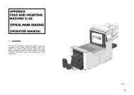
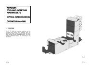
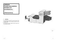
OPERATOR MANUALENGLISH1
CONTENTSSection Page Section Page1 Precautions 5 8.3 Cleaning the brushes 251.1 Special national conditions 5 8.4 Cleaning the moistening felt 252 General 6 8.5 Cleaning the sensors 252.1 Understanding the system 6 9 Options 252.2 Operating controls 7 10 Specifications 252.3 Display 83 Operating the system 83.1 Switching on 83.2 The main menu 83.3 Main menu (1) 83.4 Job info 83.5 Other job 93.6 Main menu (2) 93.7 Reset count menu 93.8 Adjustments for document feeding 93.9 Adjustments for envelope feeding 123.10 Insert position 123.11 Load ’N Go ® 134 Job programming 134.1 Job menu 134.2 Job menu (1) 134.3 Create job 134.4 Edit job 134.5 Job menu (2) 144.6 Copy job 144.7 Delete job 145 Job settings 145.1 Envelope settings 145.2 Document settings 145.3 Fold settings 155.4 Double Feed Control 165.5 OMR settings (Optional) 165.6 Job name 166 Optical Mark Reading(Optional) 166.1 Adjustments 166.2 Feeding documents 186.3 OMR code 187 Fault finding 197.1 General 197.2 Clearing stoppages 207.3 Operator troubleshooting 217.4 OMR error codes 248 Maintenance 258.1 Servicing 258.2 General cleaning 25ENGLISH3
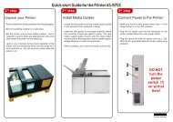
2. GENERAL2.1 Understanding the systemThis compact folding and inserting system canprocess large quantities of mail rapidly andeasily.The settings of the system are recorded in socalledjobs. These jobs can be programmed byan authorized user.As a special feature the system is equipped witha Load ’N Go ® function. The purpose of thisfunction is to start working as quickly aspossible.The system consist of the following parts:1 FlexFeed ®2 collating area3 PowerFold ®4 inserter6
2.2 Operating controlsA : envelope receiving trayB : envelope slideC: displayD : upper unitE : locking hand grip upper unitF : document feeding trayG : collator armH : collator areaI : power inlet, power switchJ : sensorsK : bellowsL : knobs for clearing stoppagesM : handle for clearing stoppagesN : water trayO : side cover (opened)ENGLISHP : side guides envelope hopperQ : knob for separation adjustmentR : envelopes support bracketS : thumbwheel for side guide adjustment7
Moistening the brushesThe water tray must always be filled with aspecial sealing liquid or water and the brushesmust be moistened. An extra set of brushes isprovided so that one set can be soaked in water.For this a special section is available in thewater tray. Refer to chapter "Maintenance".2.3 DisplayThe display shows the operating screens andkeys for operating the system (see figurebelow). The keys below are used for thefunctions: start/stop (combined key) andescape. The four keys on the right of the displayare used for the corresponding functions shownin the screens.Key12343. OPERATING THE SYSTEM3.1 Switching onThe system can be switched on or off with thepower switch on the back of the system. Referto section "Operating controls". After starting up,the display shows "main menu (1)”.3.2 The main menuThe main menu consists of two menus, "mainmenu (1)" and "main menu (2)". Press key 4 in"main menu (1)", to go to "main menu (2)".Press key 4 again to get back to "main menu(1)".3.3 Main menu (1)Main menu (1) shows the following functions(see figure above):• job info ( ),• other job,• Load ‘N Go ® .3.4 Job infoWhen key 1 is pressed in "main menu (1)", the"job info" screen will be displayed (see figurebelow). Press the escape key to go back to"main menu (1)".start/stopescPress the start/stop key to start the machine.When the start/stop key is pressed again themachine stops feeding after completing the set.It is possible that there are still documents left inthe document feeder (for example a small card).Remove all these documents from the feederbefore restarting another job. There can also beenvelopes left in the envelope track. Theseenvelopes must be removed when another typeof envelopes is required.The escape key can be used to exit a menuwithout saving any settings.The "job info" screen shows the following jobsettings:• envelope ( ) or no envelope ( ),• type of document fold ( ),• document double feed detection "on" or "off"( ),• which feeders are selected ( black isselected),• which feeders are linked ( feeder swap),• the number of documents per feeder( ),8
• the length of the document in the feeder ( ),• daily mail ( ) "on "or "off",• OMR (Optical Mark Reading) ( ) "on" or"off".• lift the document feeding tray upwards tounhook it and then pull it out from the feeder,3.5 Other jobSelect the desired job in the "Other job" menu.Confirm the job selection with "OK" which willget you back to the "main menu (1)".3.6 Main menu (2)Main menu (2) shows the following functions(see figure below):• reset count,• insert position,• job menu.3.7 Reset count menuAfter pressing key 1 in "main menu (2)", thecounter is set to zero.3.8 Adjustments for documentfeedingDocument separationThe document separation for the feeders is setautomatically.A• loosen knob B half a turn (see figure below),• grab the side guides C in the middle and pushthem outwards,• put a small stack of documents between theside guides,• grab the side guides in the middle and pushthem towards the documents,• The space between the side guides and thedocuments should be such that thedocuments have just enough play to movefreely,• re-tighten knob B,• remove the stack of documents.ENGLISHSide guidesTo adjust the side guides it is best to remove thedocument feeding tray as follows (see figurebelow):• push handle A downwards,CBReplace the document feeding tray as follows(see figure below):• place the document feeding tray under guideA,C9
• push the document feeding tray up and thenlower it into position.A10
Feeding documentsThe feeding of documents is shown in the figure below.one documentfeeder swap two documents document + enclosureno foldsingle foldletter folddoubleparallel foldAddress carrier inupper feeder.Face up and leading.Address carrier in upperlinked pair feeders.Face up and leading.Address carrier inupper feeder.Face up and leading.Address carrier in upperfeeder.Face up and leading.ENGLISHzig-zag foldAddress carrier facedown and trailing.Address carrier in lowerlinked pair feeders.Face down and trailing.Address carrier in lowerfeeder.Face down and trailing.Address carrier in upperfeeder.Face down and trailing.Daily mailThe daily mail function can be used forprocessing documents or sets which can not beprocessed automatically.The upper feeder is equipped with a daily mailswitch.Switch to daily mail in the following way:• select a job where the daily mail function hasbeen set to “on”,• turn the left side guide of the upper feederdownwards,• the daily mail handle will be visible and can beset. Push the handle towards ( ) to switchto the daily mail function. Push the handletowards ( ) to switch back to theautomatic function,• turn the left side guide upwards again.Filling the document feederOpen the left side guide by turning it downwards(or the handle for the small feeder). The feedrollers will automatically be lifted. Place a stackof documents between the side guides. Turn theleft side guide upwards again (or the handle forthe small feeder).11
3.9 Adjustments for envelopefeedingEnvelope separationAdjust the envelope separation by turning knobA (see figure below) counter clockwise until twoenvelopes (flap down and "trailing"), one on topof the other, can be moved backward andforward between the rollers without resistance.Turn knob A clockwise until one envelope willjust pass between the rollers.Envelope sealingEnvelopes can be sealed or not sealed. Toswitch sealing "on" or "off", pull the hand grip ofthe upper cover upward and pull it into thevertical position.Shift the blue handle towards to switchsealing off or towards to switch sealing on.3.10 Insert positionPress key 2 in the "main menu (2)" to enter the"Insert position" menu (see figure below).Press key 1 in the "Insert position" menu tobring one envelope onto the insert position.Side guidesThe bottom envelope must enter the separatorfirst. Adjust the side guides C (see figure above)by turning the thumbwheel D to provide enoughspace to move freely. Too much play causesskewing.Open the upper cover. The flap folding line mustbe positioned under the green indicator B (seefigure below). If necessary adjust the flap foldingline position by pressing key 2 or 3 in the "Insertposition" menu.Each key stroke stops the next envelope 0,5mm (0.02 inch) to the right (earlier) or to the left(later). Check the settings by pressing key 1again.Save the insert position settings with "OK" whichwill get you back to the "main menu (2)" again.Filling the envelope feederFan the stack of envelopes a bit and place thebottom envelope between the separation rollers(flap down and trailing). Sometimes envelopesmay skew on the insert table. The envelopesupport B (see figure above) can be rotatedslightly to compensate this. Shift the envelopesupport B in or out so that the flap side of theenvelope is lifted about 20 mm (0.8 inch). Turnthe envelope support B so that the weight of theenvelopes is distributed evenly on both sides.12
Envelope insert fingersTo adjust the insert fingers A (see figure above)loosen the knurled knob C on top of each finger.Adjust each finger so that the tip enters about 5mm (0.2 inch) into the envelope. Re-tighten theknurled knob. The fingers can be movedsideways to the desired position. Place the outerfingers D about 5 to 10 mm (0.2 to 0.4 inch) fromthe edges of the envelope.Check the position of the insert fingers whenchanging to a different type of envelope.4. JOB PROGRAMMING4.1 Job menuAfter pressing key 3 in the "main menu (2)", thedisplay shows the "job access" menu and asksfor a pin code (2324) to enter (see figure below).3.11 Load ’N Go ® .Before starting the Load ’N Go ® function (seefigure below) the adjustment of the side guidesand envelope separation must be mademanually to obtain correct operation.4.2 Job menu (1)The job menu (1) shows the following functions(see figure below):ENGLISHPress and hold key 1 to show the job info.The address carrier must be put into the upperfeeder.Only the address position can be adjusted ifneeded.TestsetPress key 2 to start a testset in the Load 'N Go ®screen. The settings of the testset will be saved.Only the feeders that feed successfully will beselected.If needed adjust the address position.In the Load ’N Go ® job the following optionscannot be used:• feeder swap (the system switchesautomatically to the upper feeder when thelower feeder is empty and vice versa),• multifeed (more sheets are fed from the samefeeder into the envelope),• the use of the Load ’N Go ® function is notpossible in the "no envelopes" mode.To go back to the main menu (1) press "esc".4.3 Create jobOnly free jobs will be shown. The "create job"menu shows the following functions.• job information ( ),• choose a higher job number,• choose a lower job number,• select the job to create and confirm with "OK"which will get you to the "job settings" menu(1).If all jobs are used the display shows "no morefree jobs".To get a free job one has to be deleted.A new selected job number starts with defaultsettings.4.4 Edit jobOnly programmed jobs will be shown. Thismenu shows the following functions:• job information ( ),13
1. set number of documents per feeder ( ).The number of sheets per feeder can be setbetween 0 and 3. A feeder can bedeselected by setting the amount ofdocuments to zero. When a feeder is set todaily mail the amount of documents isalways 1.2. set document size ( ). The document sizecan be set between 90 mm (3.54 inch) and356 mm (14 inch) in steps of 1 mm (0.04inch). For the upper station of a 2,5 stationsystem the minimum height is 115 mm (4.60inch).3. set feeder swap ( ). When feeder swap isselected the following choices are available:• select the pair of feeders that need to belinked,• select linked or unlinked for a pair of feeders,• confirm the settings by pressing “OK” whichwill get you back to the “job settings” menu.When a pair of feeders is linked, the settingsof the lower feeder will be used and shown inthe display.4. set daily mail on or off ( ). When dailymail is selected the following choices areavailable:• set the daily mail function on or off,• confirm the settings by pressing “OK” whichwill get you back to the “job settings” menu.When there are conflicting job parameters amessage will be shown.5.3 Fold settingsWhen the “fold settings” menu is selected thefollowing choices are available (see figurebelow):1. no fold ( ). When no fold is selectedthere are no settings required.2. single fold ( ). When single fold is selectedand edit is pressed, the following choices areavailable:• move the fold position to the right,• move the fold position to the left,• confirm the settings by pressing “OK” whichwill get you back to the “job settings” menu.The fold length can be minimally 75 mm (2.95 inch)and maximally the length of the longest documentused minus 25 mm (1.0 inch).3. letter fold ( ). When letter fold is selectedand edit is pressed, the following choices areavailable:• select fold number,• move the position of the fold to the right,• move the position of the fold to the left,• confirm the settings by pressing “OK” whichwill get you back to the “job settings” menu.The fold length of the first fold can be minimally 75mm (2.95 inch) and maximally the length of thelongest document used minus 50 mm (2.0 inch).The fold length of the second fold can be minimallythe length of the first fold plus 25 mm (1.0 inch)and maximally the length of the longest documentused minus 25 mm (1.0 inch).4. double parallel fold ( ). When doubleparallel fold is selected and edit is pressed,the following choices are available:• select fold number,• move the position of the fold to the right,• move the position of the fold to the left,• confirm the settings by pressing “OK” whichwill get you back to the “job settings” menu.The fold length of the first fold can be minimally 75mm (2.95 inch) and maximally the length of thelongest document used minus 50 mm (2.0 inch).The fold length of the second fold can be minimallythe length of the first fold plus 25 mm (1.0 inch)and maximally the length of the longest documentused minus 25 mm (1.0 inch).5. zig-zag fold ( ). When zig-zag fold isselected and edit is pressed, the followingchoices are available:• select fold number,• move the position of the fold to the right,• move the position of the fold to the left,ENGLISH15
• confirm the settings by pressing “OK” whichwill get you back to the “job settings” menu.The fold length of the first fold can be minimally 75mm (2.95 inch) and maximally the length of thelongest document used minus 100 mm (4.0 inch).The fold length of the second fold can be minimallythe length of the first fold plus 25 mm (1.0 inch)and maximally the length of the longest documentused minus 75 mm (3.0 inch).5.4 Double Feed ControlWhen the “DFC settings” menu is selected thefollowing functions are available (see figurebelow):6.1 AdjustmentsReading head positionThe reading head must be placed according tothe (horizontal) position of the printed marks onthe documents. To adjust the reading head,proceed as follows:• take a document with a reading code,• fold the document on the first mark (see nextfigure).5.5 OMR settings (Optional)Refer to the chapter "Optical Mark Reading".5.6 Job nameThis menu shows the following functions (seefigure below):• hold the document onto the ruler (see nextfigure),• adjust the reading head A according to themiddle of the marks,• divide the paper guides B along the width ofthe document.When the reading head is adjusted it is possiblethat some paper guides B have to be removedand replaced on the other side of the readinghead.6. OPTICAL MARK READING(OPTIONAL)The folding and inserting system can beequipped with Optical Mark Reading. With thisoption the system reads optical marks that havebeen specially printed on the documents. Thiscode contains information about the processingof the documents. A set can have a varyingnumber of sheets. The document with theprinted code is placed in the upper feeder.The replacement procedure is the reversal ofthe removal procedure.16
When OMR is selected in a job, the job infoscreen shows the OMR symbol.The OMR settingsVia the job settings the OMR 1 menu can beselected (see figure below). The OMR functioncan be activated by selecting "Reading on" or"Reading off". The upper feeder is selectedautomatically for reading. When "OK" is pressedwith "Reading off" the “job settings” menu isshown again.When "OK" is pressed with "Reading on" theOMR 2 menu is shown (see figure below). In theOMR 2 menu the distance from the top of thepage to the first mark can be set, and themaximum amount of documents in a set can bechosen. When "OK" is pressed the “job settings”menu is shown again.ENGLISHIt is not possible to put more than 5 sheets inone set.17
6.2 Feeding documentsThe feeding of documents is shown in the figure below.Fold type Type of documents Loading positionsno foldfirst page1 23single foldletter foldDoubleparallel foldaddressOMROMR stopstart readingreadingAddress carrier, face up and leading.3 21last page(duplex printed)zig-zag foldaddressOMROMR startstop readingreadingAddress carrier, face down and trailing.6.3 OMR codeFunctionIn order to handle computer printed documentsfully automatically, code marks are printed oneach document.With the first four fold types (refer to section"Feeding documents"), the first sheet of a setalways contains the address. In case of a zigzagfold the address has to be printed on thelast page of the set. A full length code is printedon every sheet of a set.The code on the last sheet of the set containsthe insert instruction. The other sheets carry theaccumulate instruction. If a parity check is used,this is checked on each sheet. If the set containsonly one sheet, it is the “last” sheet. The codemust appear in the same location on every pageregardless of the actual code length.Printing qualityCriteria:• marks should be printed in black,• marks on the same sheet must have equalintensity,• for matrix printers near letter quality (NLQ)printed characters are preferred to obtainmaximum blackness (double strike),• be aware of background “noise”. This can becolor changes on the form, backgrounddesign, a logo or copy on the opposite side ofthe sheet that will bleed through and be readby the reading head,• the ribbon or toner quality must be checked,• printing must be done on the same positionon every sheet.Minimum code/basic commandsThe minimum code is one mark in one line(insert). However for reliability it is advised touse at least 2 marks. The first line is the startmark. A mark printed on the second line meansinsert, no mark printed means accumulate (thiscan be reversed on request).18
Code position and free areaThe code must be printed minimally 15 mm(0.59 inch) away from top and 30 mm (1,18inch) from the bottom of the sheet. Default thefirst mark from the top is set to 100 mm (3.9inch). From the left hand and right hand side 7mm (0.28 inch) must be kept clear. The codemust appear in the same location, and have aconsistent number of marks on every page.LengthAbove the first mark and below the last mark aspace of 8,5 mm (0.33 inch) must be keptwithout printing. This means that the minimumcode area consists of 6 lines, 2 lines to print the(basic) and 4 lines free space. Line distancemay be 2,54 mm (0.1 inch) to 6,35 mm (0.4inch).Code width, character space and pitchThe minimum width of the code area is 7character spaces. From left to right: first 2characters space unprinted (5 mm; 0.20 inch),then the track mark (3 characters or 6,3 mm; 0.4inch) and finally 2 character spaces unprinted.Pitch 10 or 12 is accepted. The track mark canbe printed by using the “underline” sign (__),which must have a thickness of at least 0,2 mm.Parity markBy adding a parity mark the reading code can bechecked. When the OMR-2 code is used thesum of the marks has to be even.Safety markThe safety mark is used as an extra security.With skewed paper the reading head can misspart of the reading code. In these situations thesafety mark is not read, and the system will givean error. The safety mark also indicates the endof the reading code. This mark always has to beprinted on the document if it has been activated.Criteria:• the marks chosen are always used in theabove sequence,• if a function is suppressed the followingfunction will move upwards one line,• the chosen code is used on all material whichwill be processed by the Optical MarkReading,• the length of the code with it's mark definitionis a service setting.7. FAULT FINDING7.1 GeneralIn the system the following error types arepossible:• paperflow errors,• reading errors (when the system is equippedwith Optical Mark Reading),• technical errors.If an error occurs the display shows a screenwith an error description and a suggestedsolution.When a paperflow error occurs the followingfunctions are available:• show more information,• reset the error after solving the problem (theerror screen will disappear).The black arrow or a black feeder indicateswhere the problem occurs.When a reading or double feed control erroroccurs, the document stops in the collator area.The operator must remove the document(s) fromthe collator area and must complete the setmanually!When there is a technical problem the displayshows a message. The error cannot be solvedby operating personnel and assistance of theservice support is needed.First write down the error code, then switch theinserter off and on again, to verify system operation.When the error still occurs contact your serviceorganization.ENGLISH19
7.2 Clearing stoppagesFor clearing stoppages the three sections of thesystem can be opened (A, B and C).PowerFold ®Remove the documents as follows:• pull the hand grip up and pull the upper coverinto vertical position,• remove the documents from the PowerFold ® ,• close the upper cover until it clicks.Reset the error after solving the problem withkey 4.Lower envelope trackRemove the envelopes as follows (see figurebelow):• open the side cover A,• lower and hold the handle B to the left andremove the envelope(s) from the lowerenvelope track,• release the handle B,• close the side cover.Reset the error after solving the problem with(key 4).If needed, envelopes and documents can betransported manually by turning knob Cclockwise. To transport envelopes manually tothe insert table or to the lower envelope track,turn knob D clockwise.20
7.3 Operator troubleshootingSymptom Possible cause Remedy SectionThe machine cannot bestarted after switchingon.Machine not connectedto mains.Connect the machine tothe mains.Fuse is blown. Replace fuse below -power switch.A cover is opened. Close the covers --Machine stops withenvelope at insertposition (flap not open).Envelopes stackedreversed in the hopper.Check envelope feedadjustments. Placeenvelopes correctly inhopper.Adjustments forenvelope feeding.Envelope flap sticks.Wrong envelope typeused (not accordingspecifications or jobsettings).Store envelopesaccording tospecifications.Change envelopesaccording tospecifications.Specifications.Specifications.ENGLISHEnvelopes are doublefed.Envelope stop skewed.Envelope separation notcorrectly adjusted.Envelopes not placedproperly in the hopper.Side guides of theenvelope hopper are settoo wide.Check separationsettings, adjust ifneeded.Check and replace ifneeded.Check side guides andadjust if needed.Adjustments forenvelope feeding.Adjustments forenvelope feeding.Adjustments forenvelope feeding.Envelopes are fedirregularly.Hopper almost empty. Refill hopper. Adjustments forenvelope feeding.Separation set toonarrow.Side guides set toonarrow.Envelope support notpositioned correctly.Check separationsettings, adjust ifneeded.Check side guides andadjust if needed.Reposition the envelopesupport.Adjustments forenvelope feeding.Adjustments forenvelope feeding.Adjustments forenvelope feeding.Flap is wrinkled andsometimes not opened.Envelope not withinspecifications.Check specificationsand change envelopes ifneeded.Specifications.21
Symptom Possible cause Remedy SectionFlap sticks.Specifications.Flap curled.Separation set toonarrow.Store envelopesaccording tospecifications.Envelopes stored ormanufacturedimproperly.Check separationsettings, adjust ifneeded.Specifications.Adjustments forenvelope feeding.Fingers are placed ontop of the envelope.Machine stops whileinserting (stoppage atthe inserting point).Fingers adjusted toodeep into the envelope.Envelope stops tooearly.Fingers not correctlyadjusted.Inserted document toolong for used envelope.Envelope throatincorrect.Envelope glued inside.Window not gluedproperly.Check fingers position,adjust if needed.Check envelope stopposition, adjust ifneeded.Check fingers position,adjust if needed.Check fold settings.Check envelopespecifications.Eliminate faultyenvelopes.Eliminate faultyenvelopes.Envelope insert fingers.Envelope insert fingers.Envelope insert fingers.Fold settings menu.Specifications.Specifications.-Flap not sufficientlymoistened.Water level low.Check water level, refillif needed.Moistening the brushes.Brushes dry.Check brushes, replaceif needed by the extrasoaked set.Moistening the brushesor Maintenance.Brushes dirty.Check brushes, clean ifneeded.Maintenance.Moistening felt dry.Check the moisteningfelt, refill water tray ifneeded.Moistening the brushes.Moistening felt dirty.Check the moisteningfelt, clean if needed.Maintenance.Moistening brushesinactive.Activate the moisteningbrushes.Envelope sealing.22
Symptom Possible cause Remedy SectionEnvelope not filledproperly or envelopeflap not closed properly.Inserted document toobig.Document not inserteddeep enough.Check fold settings,adjust if needed.Check adjustment ofenvelope stop positionand fingers.Fold settings menu.Envelope insert position.No document fed. Feeder empty. Refill feeder. Filling the documenthopper.Separation set too wide. Adjust the separation. Document separation.Side guides set toonarrow.Adjust the side guides. Side guides.Skewed documents fed. Side guides set toowide.Adjust side guides.Side guides.ENGLISH23
7.4 OMR error codeserror description suggested solution information Error codeReading error.Remove the documents and Wrong window position. 3 : 112adjust the 1st mark from thetop position correctly.Reading error.Remove the currentSuspected set after error. 3 : 114suspected set and check thenext set.Reading error.Remove the documents and Not enough marks. 3 : 120adjust the reading head.Adjust the1st mark from thetop position correctly. Whenthe error still occurs, contactyour service organization.Reading error.Remove the documents and No basic command. 3 : 122check the used OMR code.Reading error.Remove the documents and Wrong parity in code. 3 : 126check the used OMR code.Adjust the reading head.Reading error.Remove the documents and Undefined mark found 3 : 127check the used OMR code(flex-dongle).Reading error.Remove the documents and Wrong mark distance. 3 : 128check the used OMR code’s(mark line distance).Reading error.Remove the documents and Too many marks. 3 : 129check the used OMR code(flex-dongle).Too many sheets.Remove the documents. Set size exceeded. 3 : 134Check the set and completethe set manually.Incomplete set.Remove the documents.Check the set and completethe set manually.Part of previous set. 3 : 135Service assistance is needed for the error codes with the message “technical failure”. First write downthe error code, then switch the inserter off and on again, to verify system operation. When the error stilloccurs contact your service organization.24
8. MAINTENANCE8.1 ServicingDisconnect the mains supply beforeperforming any maintenance.The user must not attempt to servicethe appliance beyond that described inthis operator manual. All otherservicing must be carried out byqualified service personnel only.Please contact your authorizeddistributor.8.2 General cleaningThe system must be kept in proper condition byregularly removing dust, paper remains, etc.Clean the sealing table and rubber rollers whendirty. This can be done by using a slightly wettedcloth soaked in warm water.Do not clean the display with water or a cleaningliquid.8.3 Cleaning the brushesClean the brushes when dirty or saturated withglue. An extra set of brushes is provided. Thebest procedure is to always soak one set ofbrushes and use the other set. In that way thereis always a clean set of brushes ready forusage.The brushes can be removed one by one bypulling them straight off the brush holder. Whenreplacing the brushes, align the studs on eachbrush with the respective holes in the brushholder.The brushes should be cleaned once a week.The sensors can be cleaned by using the bellowlocated behind the side cover.For cleaning the envelope track sensor, put thebellow in the hole (refer to the section"Operating controls"). Squeeze a few timesfirmly to blow away the dust from the sensor.Repeat this procedure for the other hole forcleaning the flap sensor.9. OPTIONSOptical Mark ReadingThe system can be equipped with optical markreading. With this reading the system readsoptical marks that have been specially printedon the documents. This code containsinformation about the processing of thedocuments.Side exitAt the rear exit a side exit can be fitted by theservice organization. The side exit can be fittedinstead of the standard envelope receiving tray.The side exit allows a conveyor, conveyor/stacker or a franking machine to be fitted in linewith the machine.When a side exit is ordered, a receiving tray willbe delivered with it. The side exit can bemounted for exiting enveloppes to the left or tothe right.10. SPECIFICATIONSThis operator manual refers to machines asfrom machine number 04 DO-5001 or higher.ENGLISH8.4 Cleaning the moistening feltClean the moistening felt and water tray whendirty or saturated with glue.8.5 Cleaning the sensorsWhen the display shows a message like “Tracksensor dusty”, the sensors on the envelope ordocument path must be cleaned. The screen onthe display indicates which sensor(s) must becleaned.25