CONTROL PANEL OPERATING MANUAL - Daikin
CONTROL PANEL OPERATING MANUAL - Daikin
CONTROL PANEL OPERATING MANUAL - Daikin

Create successful ePaper yourself
Turn your PDF publications into a flip-book with our unique Google optimized e-Paper software.
MICROTECH III <strong>CONTROL</strong>LERMICROTECH III CONTRO<strong>CONTROL</strong> <strong>PANEL</strong> <strong>OPERATING</strong> <strong>MANUAL</strong>EWWD~FZXS WATER COOLED MAGNETIC BEARINGS CHILLERSOITS Software Version: 2.01.01Control Software Version: EWWDU3UU02B
Table of ContentsIntroduction ............................................. 4Features of the Control Panel ................. 5Definitions ................................................ 6General Description................................. 9Control Panel ......................................... 10Use with On-Site Generators ............................ 11Multi-Chiller Setup ............................... 11Operating Limits: .............................................. 12Operating the Control System .............. 14Interface Panel On/Off ...................................... 14Start/Stop Unit .................................................. 14Change Setpoints .............................................. 14Alarms .............................................................. 14Component Failure ........................................... 15Component Description ........................ 15Operator Interface Touch Screen ...................... 15Controller Description ...................................... 15Navigating......................................................... 16Unit Controller ....................................... 18Unit Controller Setpoints .................................. 18Faults, Problems, Warnings .............................. 22Controller Functions ......................................... 22Compressor Controller ......................... 24Compressor Faults, Problems, Warnings .......... 25Compressor Control Functions ......................... 26Compressor On-BoardControllers .............................................. 29Operator Interface TouchScreen ...................................................... 31Navigation ........................................................ 31Screen Descriptions .......................................... 34VIEW Screens .................................................. 34SET Screens ...................................................... 39SERVICE Screen .............................................. 52HISTORY Screens ............................................ 53Download Data ................................................. 54ACTIVE ALARM Screen ................................. 55Unit Controller Menu Screens ............. 57Menu Matrix ..................................................... 58Compressor Controller MenuScreens ................................................... 76Menu Matrix ..................................................... 76BAS Interface ........................................ 78Sequence of Operation ......................... 78Operating the Chiller ControlSystem .................................................... 79Interface Panel On/Off ...................................... 79Start/Stop Unit .................................................. 79Change Setpoints .............................................. 80Alarms............................................................... 80Interface Panel Failure ...................................... 80Annual Shutdown ................................. 81Annual Startup .................................................. 81Maintenance .......................................... 82Pressure/Temperature Chart .............................. 82Routine Maintenance ........................................ 82Repair of System ............................................... 83Maintenance Schedule .......................... 86Service Programs .................................. 87Operator Schools ................................... 87Limited Warranty ................................. 87D - EOMWC00905-10EN - 2/84
Manufactured in an ISO Certified Facility©2010 <strong>Daikin</strong> International. Illustrations and data cover the <strong>Daikin</strong> International product at the time of publication and we reserve theright to make changes in design and construction at anytime without notice. ® The following are trademarks or registered trademarksof their respective companies: BACnet from ASHRAE; LONMARK, LonTalk, LONWORKS, and the LONMARK logo are managed, grantedand used by LONMARK International under a license granted by Echelon Corporation; Modbus from Schneider Electric; MicroTech II, andOpen Choices from <strong>Daikin</strong> International.Unit controllers are LONMARK certifiedwith an optional LONWORKScommunications moduleD - EOMWC00905-10EN - 3/88
IntroductionThis manual provides setup, operating, and troubleshooting information for <strong>Daikin</strong> EWWD centrifugal chillerswith the MicroTech ΙΙ® controller. Please refer to the current version of installation manual IM 1029 forinformation relating to installingthe unit.! WARNINGElectric shock hazard. Improper handling of this equipment can cause personal injury or equipment damage. Thisequipment must be properly grounded. Connections to and service of the MicroTech II control panel must be performedonly by personnel that are knowledgeable in the operation of the equipment being controlled..! CAUTIONStatic sensitive components. A static discharge while handling electronic circuit boards can cause damage to thecomponents. Discharge any static electrical charge by touching the bare metal inside the control panel before performingany service work. Never unplug any cables, circuit board terminal blocks, or power plugs while power is applied to thepanel.NOTICEThis equipment generates, uses and can radiate radio frequency energy and, if not installed and used inaccordance with this instruction manual, may cause interference to radio communications. Operation of thisequipment in a residential area is likely to cause harmful interference in which case the user will be required tocorrect the interference at the owner’s own expense.<strong>Daikin</strong> disclaims any liability resulting from any interference or for the correction thereof.Temperature and humidity considerationsThe unit controllers are designed to operate within an ambient temperature range 20°F to 130°F(-7°C to 54°C) with a maximum relative humidity of 95% (non-condensing). The unit is designed for indoor,non-freezing locations only.HAZARD IDENTIFICATION INFORMATION! DANGERDangers indicate a hazardous situation which will result in death or serious injury if notavoided.! WARNINGWarnings indicate potentially hazardous situations, which can result in property damage,severe personal injury, or death if not avoided.! CAUTIONCautions indicate potentially hazardous situations, which can result in personal injury orequipment damage if not avoided.D - EOMWC00905-10EN - 4/88
Features of the Control Panel• Control of leaving chilled water within a ±0.2°F (±0.1°C) tolerance.• Display of the following temperatures and pressures on a 15-inch Super VGA touch-screen operatorinterface• Entering and leaving chilled water temperature• Enter and leaving condenser water temperature• Saturated evaporator refrigerant temperature and pressure• Saturated condenser temperature and pressure• Outside air temperature (optional)• Suction line, liquid line and discharge line temperatures, calculated superheat for discharge andsuction lines, and calculated subcooling for liquid line• Automatic control of primary and standby evaporator and condenser pumps.• Control of up to 4 stages of cooling tower fans plus modulating bypass valve and/or tower fan VFD.Although fan staging is available, continuous, modulated control of tower capacity is preferred andrecommended.• History trend feature that will constantly log chiller functions and setpoints. The controller will store anddisplay all accumulated data for recall in a graphic format on the screen. Data can be downloaded forarchival purposes.• Three levels of security protection against unauthorized changing of setpoints and other controlparameters.• Plain language warning and fault diagnostics to inform operators of most warning or fault conditions.Warnings, problems and faults are time and date stamped for identification of when the fault conditionoccurred. In addition, the operating conditions that existed just prior to shutdown can be recalled to aidin resolving the cause of the problem.• Twenty-five previous faults and related operating conditions are available from the display. Data can beexported for archival purposes via a 3.5-inch floppy drive or other device (depending on date ofmanufacture).• Soft loading feature reduces electrical consumption and peak demand charges during system looppulldown.• Remote input signals for chilled water reset, demand limiting and unit enable.• Manual control mode allows the service technician to command the unit to different operating states.Useful for system checkout.• BAS communication capability via LONTALK®, Modbus® or BACnet® standard open protocols for mostBAS manufacturers.• Service Test mode for troubleshooting controller outputs.• Pressure transducers for direct reading of system pressures.• Preemptive control of low evaporator and high discharge pressure conditions to take corrective actionprior to a fault trip.D - EOMWC00905-10EN - 5/88
DefinitionsActive SetpointThe active setpoint is the parameter setting in effect at any given moment. This variation can occur onsetpoints that can be altered during normal operation. Resetting the chilled water leaving temperaturesetpoint by one of several methods such as return water temperature is an example.Active Capacity LimitThe active capacity setpoint is the setting in effect at any given moment. Any one of several external inputscan limit a compressor’s capacity below its maximum value.Active-Amp-LimitActive amp limit is the actual amp limit imposed by an outside signal such as the load limit function.Condenser Recirc (Recirculation) TimerA timing function, with a 30-second default, that holds off any reading of condenser water for the duration ofthe timing setting. This delay allows the sensors to take a more accurate reading of the condenser watertemperature.Dead BandThe dead band is a set of values associated with a setpoint such that a change in the variable occurring withinthe dead band causes no action from the controller. For example, if a temperature setpoint is 44°F and it hasa dead band of ± 2.0 degrees F, nothing will happen until the measured temperature is less than 42°F or morethan 46°F.DINDigital input usually followed by a number designating the number of the input.Discharge SuperheatDischarge superheat is calculated using the following equation:Discharge Superheat = Discharge Temperature – Condenser Saturated TemperatureErrorIn the context of this manual, “Error” is the difference between the actual value of a variable and the targetsetting or setpoint.Evaporator ApproachThe evaporator approach is calculated for each circuit. The equation is as follows:Evaporator Approach = LWT – Evaporator Saturated TemperatureEvap Hold-loadingThis is a setpoint that establishes the minimum evaporator pressure to which the chiller is allowed to go. Itsignals that the unit is at full load so the no further loading will occur that would lower the pressure evenfurther.Evap Recirc (Evaporation Recirculation) TimerA timing function, with a 30-second default, that holds off any reading of chilled water for the duration of thetiming setting. This delay allows the chilled water sensors to take a more accurate reading of the chilledwater temperature.EXVElectronic expansion valve, used to control the flow of refrigerant to the evaporator, controlled by the circuitmicroprocessor.D - EOMWC00905-10EN - 6/88
Load LimitAn external signal from the keypad, the BAS, or a 4-20 ma signal that limits the compressor loading to adesignated percent of full load. Used to limit unit power input.Load BalanceLoad balance is a technique that equally distributes the total unit load between two or more runningcompressors.Low Pressure Hold (Inhibit) SetpointThe psi evaporator pressure setting at which the controller will not allow further compressor loading.“Hold” and “Inhibit” are used interchangeably.Low Pressure Unload SetpointThe psi evaporator pressure setting at which the controller will unload the compressor in an effort tomaintain the minimum setting.LWTEvaporator leaving water temperature. The “water” is any fluid used in the chiller circuit.LWT ErrorError in the controller context is the difference between the value of a variable and the setpoint. Forexample, if the LWT setpoint is 44°F and the actual temperature of the water at a given moment is 46°F,the LWT error is +2 degrees.LWT SlopeThe LWT slope is an indication of the trend of the chilled water temperature. It is calculated by takingreadings of the temperature every few seconds and subtracting them from the previous value over arolling one-minute interval.msMilli-secondMaximum Saturated Condenser TemperatureThe maximum saturated condenser temperature allowed is calculated based on the compressoroperational envelope.OATOutside ambient air temperatureOffsetOffset is the difference between the actual value of a variable (such as temperature or pressure) and thereading shown on the microprocessor as a result of the sensor signal.OITSOperator Interface Touch Screen, one screen per unit provides operating data visually and accommodatessetpoint entry.pLANPeco Local Area Network is the proprietary name of the network connecting the control elements.Refrigerant Saturated TemperatureRefrigerant saturated temperature is calculated from the pressure sensor readings. The pressure is fittedto an R-134a temperature/pressure curve to determine the saturated temperature.Soft LoadSoft Load is a control sub-routine that allows the chiller to load up gradually. It requires setpoint inputsof selecting it by Yes or No inputs by selecting the percent load to start ramping up and by selecting thetime to ramp up to full load (up to 60 minutes).D - EOMWC00905-10EN - 7/88
SPSetpointSuction SuperheatSuction superheat is calculated for each circuit using the following equation:Suction Superheat = Suction Temperature – Evaporator Saturated TemperatureStageup/Stagedown Delta-TStaging is the act of starting or stopping a compressor or fan when another is still operating. Startup and Stopis the act of starting the first compressor or fan and stopping the last compressor or fan. The Delta-T is the“dead band” on either side the setpoint in which no action is taken.Stage Up DelayThe time delay from the start of the first compressor to the start of the second.Startup Delta-TNumber of degrees above the LWT setpoint required to start the first compressor.Stop Delta-TNumber of degrees below the LWT setpoint required for the last compressor to stop.VDCVolts, Direct Current; sometimes noted as vdc.VFDVariable Frequency Drive, a device located on the compressor used to vary the compressor speed.D - EOMWC00905-10EN - 8/88
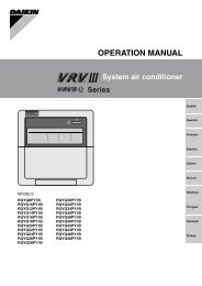
General DescriptionMajor ComponentsFigure 1, Major Component LocationUnit Control PanelEvaporator ReliefValve, Behind PanelCompressor #1Compressor #2OperatorInterfacePanel (OITS)CondenserRelief ValvesBehind PanelPower Panel(Front End Box)Control PanelElectronic Expansion ValveGeneral DescriptionThe centrifugal MicroTech ΙΙ control system consists of a microprocessor-based controller in the controlpanel, as well as on-board the compressors, providing monitoring and control functions required for thecontrolled, efficient operation of the chiller. The system consists of the following components:• Operator Interface Touch Screen (OITS), one per unit-provides unit information and is the primarysetpoint input instrument. It has no control function.• Unit Controller, controls unit functions and communicates with other auxiliaries. It is the secondarylocation for setpoint input if, and only if, the OITS is inoperative.• On-board compressor controller mounted on each compressor that monitors compressor operation andcontrols bearing operation.The operator can monitor all operating conditions by using the unit-mounted OITS. In addition to providingall normal operating controls, the MicroTech II control system monitors equipment protection devices on theunit and will take corrective action if the chiller is operating outside of its normal design conditions. If a faultcondition develops, the controller will shut a compressor, or the entire unit, down and activate an alarmoutput. Important operating conditions at the time an alarm condition occurs are retained in the controller’smemory to aid in troubleshooting and fault analysis.The system is password protected and only allows access by authorized personnel. The operator must enterthe password into the touch screen (or one of the controller's keypad) before any setpoints can be altered.D - EOMWC00905-10EN - 9/88
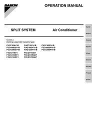
Control PanelFigure 2, Control PanelEXV BoardField Wiring KnockoutsOn/OffSwitchesUNITCOMP #1COMP #2Terminal BoardTB UTB1 for FieldWiring ConnectionsControllerUniversalCommunicationModuleOITS PCEmergencyShutdown Switch,Outside PanelComp #1 I/OComp #2 I/OThe unit controller, the OITS microprocessor, the unit and compressor on/off switches and other minorcomponents are mounted in the control panel. The switches are designated “I” for on and “0” for off. Thecompressor on/off switch should only be used when an immediate stop is required since the normal shutdown sequence is bypassed.The switch panel also has a circuit breaker that interrupts power to the cooling tower fans, valves, andevaporator and condenser pumps, if any of these are tied into the MicroTech II controller for control of theiroperation. If these components operate independently from the chiller control, the breaker has no effect.The unit controller's function is acquiring and processing data relating to the chiller operation and issueinginstructions to various components to maintain controlled operation. The unit controller also sendsinformation to the OITS for graphic display. The controller has a 4x20 LCD display and keys for accessingdata and changing setpoints. If the OITS should become inoperable.The controller LCD can display most ofthe same information as the OITS and can operate the chiller independently if the OITS is not available.D - EOMWC00905-10EN - 10/88
Use with On-Site GeneratorsEWWD chillers have their total tonnage divided between two compressors (all but single compressor ModelEWWD 145S) that start sequentially and they are operated with variable frequency drives. These features makeEWWD chillers especially appropriate for use in applications where they may be required to run with on-siteelectrical generators. This is particularly true when the generators are used for temporary power when the utilitypower is lost.Starting/Stopping Procedure: The stopping of the chiller in the event of a power failure is typically uneventful.The chiller will sense a loss of voltage and the compressors will stop, coasting down using power generatedfrom their dynamic braking to maintain the bearing magnetic field. The stop signal will initiate a three-minutestop-to-start timer, effectively preventing compressor restart for three minutes. The timer is adjustable fromthree to fifteen minutes, but the recommended and default value is three minutes. This interval allows thegenerator sufficient time to get up to speed and stabilize. The chiller will restart automatically when the start-tostarttimer expires.Transfer Back to Grid Power: Proper transfer from stand-by generator power back to grid power is essential toavoid compressor damage.! WARNINGStop the chiller before transferring supply power from the generator back to the utility power grid.Transferring power while the chiller is running can cause severe compressor damage.The necessary procedure for reconnecting power from the generator back to the utility grid is show below.These procedures are not peculiar to <strong>Daikin</strong> units only, but should be observed for any chiller manufacturer.1. Set the generator to always run five minutes longer than the unit start-to-start timer, which could be setfrom 15 to 60 minutes. The actual setting can be viewed on the operator interface panel on theSetpoint/Timer screen.2. Configure the transfer switch, provided with the generator, to automatically shut down the chiller beforetransfer is made. The automatic shut-off function can be accomplished through a BAS interface or withthe “remote on/off” wiring connection shown in Figure 8 on page 30. A start signal can be given anytimeafter the stop signal since the three-minute start-to-start timer will be in effect.Chiller Control Power: For proper operation on standby power, the chiller control power must remain asfactory-wired from a unit-mounted transformer. Do not supply chiller control power from an external powersource because the chiller may not sense a loss of power and do a normal shutdown sequence.Multi-Chiller SetupComponent DescriptionCommunication SetupThe communication wiring and setup required for dual compressor operation is performed in thefactory and should be reviewed when the chiller is initially started after installation or if there is anychange made in the chiller control hardware.RS485 communication wiring between chillers should be field wired before start-up and installed asa NEC Class 1 wiring system.D - EOMWC00905-10EN - 11/88
Table 1, Address DIP Switch Settings for Controllers Using Multi-chiller communicationChiller Comp 1 Comp 2UnitOperatorReservedControllerInterfaceReservedA1 2 5 6 7 8100000 010000 101000 011000 111000 000100B9 10 13 14 15 16100100 010100 101100 011100 111100 000010NOTES:1. Two EWWD units can be interconnected.2. The interface setting is not a DIP switch setting. The ‘Operator Interface Touch Screen’ (OITS) addressis selected by selecting the ‘service’ set screen. Then, with the Technician level password active, select the‘pLAN Comm’ button. Buttons A(7), B(15), C(23), D(31) will appear in the middle of the screen, then selectthe letter for the OITS address for the chiller that it is on. Then close the screen. Note that A is the defaultsetting from the factory.3. There are six Binary DIP Switches: Up is ‘On’, indicated by ‘1’. Down is ‘Off’, indicated by ‘0’. Theyare slide and not rocker switches. They are located on the upper-left corner of the face of the controller.Operator Interface Touch Screen (OITS) SettingsSettings for any type of linked multiple compressor operation must be made to the MicroTech II controller.Settings on a dual compressor unit are made in the factory prior to shipment, but must be verified in the fieldbefore startup. Settings for multiple chiller installations are set in the field on the Operator Interface TouchScreen as follows:Maximum Compressors ON – SETPOINTS - MODES screen, Selection #10 = 2 for a EWWD, 4 for 2EWWDs.Sequence and Staging – SETPOINTS - MODES screen, Selection #11 & #13; #12 & #14. Sequence sets thesequence in which compressors will start. Setting all to “1” evokes the automatic lead/lag feature and is thepreferred setting.Nominal Capacity – SETPOINTS - MOTOR screen, Selection #10. The setting is the compressor designtons. Compressors on dual units are always of equal capacity.Communication Setup1. With no communication connections between chillers, disconnect control power and set the DIP switchesas shown inD - EOMWC00905-10EN - 12/88
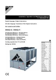
Table 1.2. With all manual switches off, turn on control power to each chiller and set each OITS address (see Note 2above).3. Verify correct nodes on each OITS Service Screen.4. Connect chillers together (pLAN, RS485, between J6 connections on each unit’s isolation boards. Theboards are not furnished, separate RS485 isolators must be field supplied.5. Verify correct nodes on each OITS Service Screen. See Figure 26 on page 52.Operating Limits:Maximum standby ambient temperature, 130°F (55°C)Minimum operating ambient temperature (standard), 35°F (2°C)Leaving chilled water temperature, 36°F to 60°F (2.2°C to 15°C)Maximum operating evaporator inlet fluid temperature, 66°F (19°C)Maximum startup evaporator inlet fluid temperature, 90°F (32°C)Maximum non-operating inlet fluid temperature, 100°F (38°C)Minimum condenser water entering temperature, 55°F (12.8°C)Maximum condenser entering temperature, 105F (40.6C)Maximum condenser leaving temperature, 115F (46.1C)Low Condenser Water Temperature OperationWhen the ambient wet bulb temperature is lower than design, the entering condenser water temperature canbe allowed to fall to improve chiller performance. This is especially true of an advanced design such as the<strong>Daikin</strong> EWWD chiller that features variable compressor speed.It is an engineering fact that as the compressor discharge pressure is reduced, the amount of power to pumpa given amount of gas also is reduced. The reduction can result in significant energy savings.However, as with most centrifugal chiller applications, a tower bypass valve must be installed and must becontrolled by the chiller MicroTech II controller. Figure 3 illustrates two temperature actuated towerbypass arrangements. The “Cold Weather” scheme provides better startup under cold ambient airtemperature conditions. The check valve may be required to prevent entraining air at the pump inlet.Figure 3, Bypass, Mild Weather OperationBypass, Cold Weather OperationD - EOMWC00905-10EN - 13/88
Operating the Control SystemInterface Panel On/OffThe Operator Interface Panel is turned on and off with a switch located at the lower front of the panel.Screen control buttons are located to either side of it and elicit on-screen prompts when pressed.The screen is equipped with a screen saver that blackens the screen. Touching the screen anywherereactivates the screen. If the screen is black, touch it first to be sure it is on before using the ON/OFF botton.Start/Stop UnitThere are four ways to start or stop the chiller. Three are shown below and selected in SETPOINT\MODE\SP3; the fourth way is through panel-mounted switches:1. Operator Interface Panel (LOCAL)Home Screen 1 has AUTO and STOP buttons that are only active when the unit is in "LOCAL<strong>CONTROL</strong>." This prevents the unit from being accidentally started or stopped when it is normally undercontrol from a remote switch or BAS. When these buttons are pressed, the unit will cycle through itsnormal starting or stopping sequence.2. Remote SWITCHSelecting SWITCH in SP3 will put the unit under the control of a remote switch that must be wired intothe control panel (see Figure 8 on page 9).3. BASBAS input is field-wired into a module that is factory-installed on the unit controller.Control Panel SwitchesThe unit control panel, located adjacent to the Interface Panel, has switches inside the panel for stopping theentire unit or individual compressors. When the UNIT switch is placed in the OFF position, the chiller willshut down through the normal shutdown sequence whether one or two compressors are on.The COMPRESSOR switches will immediately shut down the compressor without going through theshutdown sequence when placed in the OFF position. It is equivalent to an emergency stop switch.Change SetpointsSetpoints are easily changed on the Operator Interface Touch Screen (OITS). A complete description of theprocedure begins on page 40. Setpoints can also be changed in the unit controller, but this is notrecommended except in an emergency when the OITS is unavailable.AlarmsA red ALARM light in the lower middle of any OITS screen is illuminated if there is an alarm. If the optionalremote alarm is wired in, it too will be energized.There are three types of alarms:• Fault, equipment protection alarms that shut a unit or compressor off.• Problem, limit alarms that limit compressor loading in response to an out-of-normal condition. If thecondition that caused a limit alarm is corrected, the alarm light will be cleared automatically.• Warning, notification only, no action taken by controller.Any type will light the ALARM light. Procedures for dealing with alarms are shown below:1. Press the alarm light button. This will go directly to the ACTIVE ALARMS screen.2. The alarm description (with date stamp) will be shown.D - EOMWC00905-10EN - 14/88
3. Press the ACKNOWLEDGE button to recognize the alarm.4. Correct the condition causing the alarm.5. Press the CLEAR button to clear the alarm from the controller. If the fault condition is not fixed, thealarm will continue to be on and the unit will not be able to be restarted.Component FailureChiller Operation without the Operator Interface PanelThe Operator Interface Touch Screen communicates with the unit controller, displaying data and transmittingtouch screen inputs to the controllers. It does no actual controlling and the chiller can operate without it.Should the Touch Screen become inoperable, no commands are necessary for continuing unit operation. Allnormal inputs and outputs will remain functional. The unit controller can be used to view operational data, toclear alarms and to change setpoints, if necessary.Component DescriptionOperator Interface Touch ScreenThe operator interface touch screen (OITS) is the primarydevice for entering commands and entries into the controlsystem. (Settings can also be made directly into the unitcontroller.) The OITS can also display controller data andinformation on a series of graphic screens. A single OITS isused per unit.Selected information from the OITS panel can be downloadedvia a USB port located in the unit control panel.The OITS panel is mounted on a moveable arm to allowplacement in a convenient position for the operator.There is a screen-saver programed into the system.screen is reactivated by touching it anywhere.Controller DescriptionHardware StructureThe controller is fitted with a microprocessor for running the control program. There are terminals forconnection to the controlled devices (for example: solenoid valves, tower fans, pumps). The program andsettings are saved permanently in FLASH memory, preventing data loss in the event of power failure withoutrequiring a back-up battery.The controller connects to other control boards, the on-board compressor microprocessors and the OITS via alocal communications network. The controller can also have an optional module to provide communicationfor a BAS using standard open protocols.TheD - EOMWC00905-10EN - 15/88
KeypadA 4-line by 20-character/line liquid crystal display and 6-button keypad is mounted on the controller. Itslayout is shown below.Figure 4, Controller KeypadRed Alarm Light BehindKey-to-Screen PathwayMENU KeyAir Conditioning
c) After selecting this second level, the desired screen can be acquired using the arrow keys. A typicalfinal screen is shown below.Pressing the MENU key from any menu screen will automatically return you to the MENU mode.Figure 5, Typical Menu Display and Keypad LayoutAir ConditioningVIEW UNIT STATUSUnit = COOLCompr. #1/#2=OFF/OFFEvap Pump = RUNMENU KeyARROW KeysENTER KeyMenu ScreensA hierarchical menu structure is used to access the various screens. Each menu screen can have one to fourlines of information. Optionally, the last menu selection can access one of a set of screens that can benavigated with the UP/DOWN arrow keys (see the scrolled menu structure below). Menu selection isinitiated by pressing the MENU key, which changes the display from a data screen to a menu screen. Menuselections are then made using the arrow keys according to labels on the right side of the display (the arrowsare ignored). When the last menu item is selected, the display changes to the selected data screen. Anexample follows showing the selection of the “VIEW COMPRESSOR (n) screen. Suppose the initial screenis:ALARM LOG(data)(data)(data)After pressing the MENU button, the top-level menu screen willshow:< ALARM< VIEW< SET
Unit ControllerTable 2, Unit Controller, Analog Inputs# Description Signal Source Range1 Reset of Leaving Water Temperature 4-20 mA Current 0-(10 to 80°F)2Entering Evaporator WaterTemperatureNTC Thermistor (10k@25°C) -58 to 212°F3Entering Condenser WaterTemperatureNTC Thermistor (10k@25°C) -58 to 212°F4 Leaving Condenser Water Temperature NTC Thermistor (10k@25°C) -58 to 212°F5 Liquid Line Refrigerant Temperature NTC Thermistor (10k@25°C) -58 to 212°F6 Demand Limit 4-20 mA Current 0-100 %RLA7 Evaporator Water Flow 4 to 20 mA Current 0 to 10,000 gpm8 Condenser Water Flow 4 to 20 mA Current 0 to 10,000 gpm9 Refrigerant Leak Sensor 4 to 20 mA Current 0 to 100 ppm10 Leaving Evaporator Water Temperature NTC Thermistor (10k@25°C) -58 to 212°FTable 3, Unit Controller, Digital Inputs# Description Signal Signal1 Unit OFF Switch 0 VAC (Stop) 24 VAC (Auto)2 Remote Start/Stop 0 VAC (Stop) 24 VAC (Start)3 Not Used4 Evaporator Water Flow Switch 0 VAC (No Flow) 24 VAC (Flow)5 Condenser Water Flow Switch 0 VAC (No Flow) 24 VAC (Flow)6 Manual Off 0 VAC (Off) 24 VAC (Auto)7 Evaporator Water Flow Switch 0 VAC (No Flow) 24 VAC (Flow)8 Condenser Water Flow Switch 0 VAC (No Flow) 24 VAC (Flow)Table 4, Unit Controller, Digital Outputs# Description Load Output OFF Output ON1 Evaporator Water Pump #1 Pump Contactor Pump OFF Pump ON2 Evaporator Water Pump #2 Pump Contactor Pump OFF Pump ON3 Condenser Water Pump #1 Pump Contactor Pump OFF Pump ON4 Condenser Water Pump #2 Pump Contactor Pump OFF Pump ON5 Tower Fan #1 Fan Contactor Fan OFF Fan ON6 Tower Fan #2 Fan Contactor Fan OFF Fan ON7 Spare8 Alarm Alarm Indicator Alarm OFF Alarm ON9 Tower Fan #3 Fan Contactor Fan OFF Fan ON10 Tower Fan #4 Fan Contactor Fan OFF Fan ON11 Compressor Off Emer. SolenoidTable 5, Unit Controller, Analog OutputsCircuit BreakerONCircuit BreakerOFF# Description Output Signal Range1 Cooling Tower Bypass Valve Position 0 to 10 VDC 0 to 100% Open2 Cooling Tower VFD Speed 0 to 10 VDC 0 to 100%3 EXV signal to IB Valve Control Bd. 0 to 10 VDC 0 to 100%4 Y3 Electronic Expansion Valve 0 to 10 VDC 0 to 100% OpenUnit Controller SetpointsThe following parameters are remembered during power off, are factory set to the Default value, and can beadjusted to any value in the Range column.The “Type” column defines whether the setpoint is part of a coordinated set of duplicate setpoints in differentcontrollers. There are three possibilities as given below:N = Normal setpoint - Not copied from, or copied to, any other controller.M = Master setpoint - Setpoint is copied to all controllers in the “Sent To” column.D - EOMWC00905-10EN - 18/88
S = Slave setpoint - Setpoint is a copy of the master setpoint (in the unit controller).D - EOMWC00905-10EN - 19/88
At power-up the slave node checks if the master node is operational and if so, it sets its copy of the setpointequal to the master’s. Otherwise, the setpoint remains unchanged. During normal operation, any time themaster setpoint changes, the slave is updated as well.The PW (password) column indicates the password that must be active in order to change the setpoint. Codesare as follows:O = Operator, M = Manager, T = Technician (not available through the 4x20 display/keypad).The following table groups setpoints that relate to the entire unit operation and are stored in the unitcontroller. All settings are made through the OITSTable 6, Controller SetpointsDescription Default Range Type PWUnitUnit Enable OFF OFF, ON M OControl SourceKEYPADKEYPAD, BAS,DIGITAL INPUTN ODisplay Units °F/psi °F/psi, °C/kPa N OLanguage ENGLISH ENGLISH, (TBD) N OBAS ProtocolNONENONE, BACnet, LonWorks,MODBUS, N2N MMotor AmpsDemand Limit OFF OFF, ON N OMinimum Amps 40% 20 to 80% N TMaximum Amps 100% 40 to 100% N TSoft Load OFF OFF, ON D MBegin Amp Limit 40% 20 to 100% N MSoft Load Ramp 5 min 1 to 60 min D MMaximum Rate 0.5 °F/min 0.1 to 5.0 °F/min D MMinimum Rate 0.1 °F/min 0.0 to 5.0 °F/min D MStagingMode Normal Normal, Efficiency, Pump, Standby N MSequence # 1 1,2, … (# of Compressors) N MMaximum Compressors ON 16 1-16 G MStage Delta T 1.0 0.5-5.0 G MFull Load 120 sec 30 to 300 sec N TAbsolute Capacity 100 Tons 0 to 9999 Tons D TLeaving WaterCool LWT 44. 0°F 40.0 to 80.0 °F M OStartup Delta T 3.0°F 0.0 to 10.0 °F M OShutdown Delta T 3.0°F 0.0 to 3.0 °F M OLWT Reset Type NONE NONE, RETURN, 4-20mA N MMax Reset Delta T 0.0°F 0.0 to 20.0 °F N MStart Reset Delta T 10. 0°F 0.0 to 20.0 °F N MTimersEvap Recirculate 30 sec 15 sec to 5 min N MStart-Start 40 min 15 to 60 min N MStop-Start 3 min 3 to 20 min N MSource No Start 70 °F 50 to 100 °F D TPumpsEvap PumpPump #1 Pump #1 Only, Pump #2 Only, AutoOnlyLead, #1 Primary, #2 PrimaryN MCond PumpPump #1 Pump #1 Only, Pump #2 Only, AutoOnlyLead, #1 Primary, #2 PrimaryN MCooling TowerTower Control None None, Temperature, Lift N MTower Stages 2 1 to 4 N MContinued on next pageD - EOMWC00905-10EN - 20/88
Description Default Range Type PWStage Up Time 2 min 1 to 60 min N MStage Down Time 5 min 1 to 60 min N MStage Differential (Temp) 3.0 °F 1.0 to 10.0 °F N MStage Differential (Lift) 6.0 psi 1.0 to 20.0 psi N MStage #1 On (Temp) 70 °F 40 to 120 °F N MStage #2 On (Temp) 75 °F 40 to 120 °F N MStage #3 On (Temp) 80 °F 40 to 120 °F N MStage #4 On (Temp) 85 °F 40 to 120 °F N MStage #1 On (Lift) 35 psi 10 to 130 psi N MStage #2 On (Lift) 45 psi 10 to 130 psi N MStage #3 On (Lift) 55 psi 10 to 130 psi N MStage #4 On (Lift) 65 psi 10 to 130 psi N MCooling Tower Valve / VFDValve/VFD ControlNoneNone, Valve Setpoint, Valve Stage,VFD Stage, Valve SP/VFD StageN MValve Setpoint (Temp) 65 °F 40 to 120 °F N MValve Setpoint (Lift) 30 psi 10 to 130 psi N MValve Deadband (Temp) 2.0 °F 1.0 to 10.0 °F N MValve Deadband (Lift) 4.0 psi 1.0 to 20.0 psi N MStage Down @ 20% 0 to 100% N MStage Up @ 80% 0 to 100% N MValve Control Range (Min) 10% 0 to 100% N MValve Control Range(Max) 90% 0 to 100% N MValve TypeNC(To Tower)NC, NO N MMinimum Start Position 0% 0 to 100% N MMinimum Position @ 60 °F 0 to 100 °F N MMaximum Start Position 100% 0 to 100% N MMaximum Position @ 90 °F 0 to 100 °F N MError Gain 25 10 to 99 N MSlope Gain 25 10 to 99 N MAlarmsEvaporator Freeze 34.0 °F -9.0 to 45.0 °F D TCondenser Freeze 34.0 °F -9.0 to 45.0 °F D TLow Evap Pressure 26 psi 10 to 45 psi D TLow Evap Pressure-Inhibit 38 psi 20 to 45 psi D TLow Evap Pressure-Unload 31 psi 20 to 45 psi D THigh Discharge Temperature-Shutdown190 °F 120 to 240 °F N THigh Discharge Temperature-Load170 °F 120 to 240 °F N THigh Condenser Pressure 140 psi 120 to 240 psi D TMotor Current Threshold 10% 1 to 20% N TSurge High Suction SH - Start 50 °F 25 to 90 °F N TSurge High Suction SH - Run 25 °F 5 to 45 °F N TServiceVane Mode AUTO AUTO, <strong>MANUAL</strong> N TUnload Timer 10 sec 10 to 240 sec N TSTOP Timer 1 sec 1 to 240 sec N TThese setpoints are normally viewed or changed on the OITS.D - EOMWC00905-10EN - 21/88
Faults, Problems, WarningsFaults (Equipment Protection Shutdowns)There are no Unit protection shutdown alarms; all such alarms are handled through the compressorcontrollers.Problems (Limit Alarms)The following alarms limit operation of the chiller in some way as described in the Action Taken column.Table 7, Controller Limit AlarmsDescription Occurs When: Action Taken ResetEvaporator Pump #1FaultEvaporator Pump #2FaultCondenser Pump #1FaultCondenser Pump #2FaultEntering EvaporatorWater TemperatureSensor FaultNo flow indicated for (5 sec) with Evaporator Pump #1 ONAND [the other pump is available (per the Evap PumpSP) AND has not faulted]No flow indicated for (5 sec) with Evaporator Pump #2 ONAND [the other pump is available (per the Evap PumpSP) AND has not faulted]No flow indicated for (5 sec) with Condenser Pump #1 ONAND [the other pump is available (per the Evap PumpSP) AND has not faulted]No flow indicated for (5 sec) with Condenser Pump #2 ONAND [the other pump is available (per the Evap PumpSP) AND has not faulted]Sensor fault AND leaving water reset is based on enteringwaterStart pump #2Start pump #1Start pump #2Start pump #1Reset mode isset to No ResetManualManualManualManualManual.(Reset modegoes back toEnteringWater)WarningsThe following “alarms” only generate a warning message to the operator. Chiller operation is not affected.Table 8, Controller WarningsDescription Occurs When: Action Taken ResetEntering Evaporator TemperatureSensor FaultEntering Condenser TemperatureSensor FaultLeaving Condenser TemperatureSensor FaultLiquid Line RefrigerantTemperature Sensor FaultController FunctionsD - EOMWC00905-10EN - 22/88Sensor is open or shorted Annunciation AutomaticSensor is open or shorted Annunciation AutomaticSensor is open or shorted Annunciation AutomaticSensor is open or shorted Annunciation AutomaticLeaving Water Temperature (LWT) ResetThe Active Leaving Water variable shall be set to the current Leaving Water Temperature (LWT) setpointunless modified by one of the reset methods below. (The current LWT setpoint is Cool LWT as determinedby the chiller mode.) The type of reset in effect is determined by the LWT Reset Type setpoint.Reset Type – NONEThe Active Leaving Water variable is set equal to the current LWT setpoint.Reset Type – RETURNThe Active Leaving Water variable is adjusted by the return water temperature.When the chiller mode = COOL, the Active Leaving Water variable is reset using the following parameters:
1. Cool LWT setpoint2. Max Reset Delta T setpoint3. Start Reset Delta T setpointReset is accomplished by changing the Active Leaving Water variable from the (Cool LWT setpoint) to the(Cool LWT setpoint + Max Reset Delta T setpoint) when the evaporator (return – leaving) water temperaturedelta varies from the (Start Reset Delta T setpoint) to 0.The Active Leaving Water variable is set equal to the Cool LWT setpoint if the reset signal is less than orequal to 4 mA. It is set equal to (Cool LWT setpoint + Max Reset Delta T setpoint) if the reset signal equalsor exceeds 20 mA. The Active Leaving Water variable will vary linearly between these extremes if the resetsignal is between 4 mA and 20 mA. An example of this action is shown below.(54.0°F)LWT Reset (Cool mode)(temperatures are examples only)Max Reset Delta T(10.0°F)Cool LWT Set-Point(44.0°F)0 ma4 ma20 maD - EOMWC00905-10EN - 23/88
Compressor ControllerThe compressor controller's primary function is controlling and protecting the compressor. No setpoints areinput to it. There is one compressor controller for each compressor on the unit. The compressor controllerreceives, processes, and sends data to the unit controller, the compressor on-board microprocessors and toexternal devices. With some operator intervention the compressor controller can operate the compressor if theoperator interface touch screen is unavailable. Inputs and outputs are as follows:Table 9, Compressor Controller, Analog Inputs# Description Signal Source Range12 Spare3 Motor Current 0 to 5 VDC 0 to 125% RLATable 10, Compressor Controller, Digital Inputs# Description Signal Signal12 Spare3 Spare4 Spare5 Spare6 Spare7 Evaporator Water Flow Switch 0 VAC (No Flow) 24 VAC (Flow)8 Condenser Water Flow Switch 0 VAC (No Flow) 24 VAC (Flow)9 SpareTable 11, Compressor Controller, Analog Outputs# Description Output Signal Range1 SpareTable 12, Compressor Controller, Digital Outputs# Description Load Output OFF Output ON12 Spare3 Spare4 Spare5 Spare6 Spare7 Spare8 Inter Lock Solenoid Comp Disabled OFF Comp. Enabled ON9 SpareD - EOMWC00905-10EN - 24/88
Compressor Faults, Problems, WarningsFaults (Equipment Protection Shutdowns)Equipment protection faults cause rapid compressor shutdown. The compressor is stopped immediately (ifthe compressor was running).The following table identifies each alarm, gives the condition that causes the alarm to occur, and states theaction taken because of the alarm. All equipment protection alarms require a manual reset.These faults are accessed by first selecting Comp 1 or Comp 2 on the controller screenTable 13, Compressor Faults (Equipment Protection Shutdowns)Description Occurs When: Action TakenLow Evaporator Pressure Evaporator Press < Low Evap Pressure SP Rapid StopHigh Condenser Pressure Cond Press > High Condenser Pressure SP Rapid StopLow Motor Current I < Motor Current Threshold with Compressor ON for 30 sec Rapid StopHigh Discharge Temperature Temp > High Discharge Temperature SP Rapid StopMechanical High Pressure Digital Input = High Pressure Rapid StopHigh Motor Temperature Digital Input = High Temperature Rapid StopSurge High Suct SH-StartingTemp > Surge High Suct SH-Start SP during first 5 minutesof Compressor ONRapid StopSurge High Suct SH-RunningTemp > Surge High Suct SH-Run SP after first 5 minutes ofCompressor ONRapid StopNo Compressor Stop%RLA > Motor Current Threshold SP with Compressor OFFfor 30 secAnnunciationStarter FaultStarter Fault Digital Input = Fault AND Compressor State =START, INTLOK, RUN, or UNLOADRapid StopLeaving Evaporator WaterTemperature Sensor FaultSensor shorted or openRapid StopEvaporator Pressure Sensor Fault Sensor shorted or open Rapid StopCondenser Pressure Sensor Fault Sensor shorted or open Rapid StopSuction Temperature Sensor Fault Sensor shorted or open Rapid StopDischarge Temperature SensorFaultSensor shorted or openRapid StopEvaporator Water Flow Loss Evaporator Flow DI = No Flow for > 10 sec Rapid StopCondenser Water Flow Loss Condenser Flow DI = No Flow for > 10 sec Rapid StopCompressor Events (Limit Alarms)The following alarms do not cause compressor shutdown but limit operation of the chiller as described in theAction Taken column.Table 14, Compressor EventsDescription Occurs When: Action Taken Automatic ResetLow Evaporator Pressure– Inhibit LoadingLow Evaporator Pressure– UnloadEvaporator FreezeProtectCondenser FreezeProtectHigh DischargeTemperaturePressure < Low Evap Pressure–InhibitsetpointPressure < Low Evap Pressure–UnloadsetpointEvap Sat Refr Temp < Evaporator FreezesetpointCond Sat Refr Temp < Condenser FreezeSetpointTemperature > High DischargeTemperature-Load SP ANDSuction superheat < 15°FInhibit loadingUnloadStart evaporatorpumpStart condenserpumpLoadEvap Press rises above(SP + 3psi)Evap Press rises above(SP + 3psi)Temp > (Evaporator FreezeSP + 2°F)Temp > (Condenser FreezeSP + 2°F)Temp < (High Dsch TempLoad SP – 3°F) ORSuperheat > 18°FD - EOMWC00905-10EN - 25/88
Configuration Rules1. Each standby compressor must have a sequence number greater than or equal to all non-standbycompressors for which it is in standby.2. All compressors in an “efficiency priority” or “pump priority” group must be set to the same sequencenumber.Compressor State Control (Comp State)Operation of the compressor is controlled by the state-transition diagram shown below. A state variable(Comp State) shall be used to maintain the current state (OFF, START, INTLOK, RUN, UNLOAD, or STOP).Transitions from one state to another are controlled by the condition statements in the TEST boxes. TASKboxes indicate actions that must be performed.Figure 6,Compressor StateTEST: Motor Current < Motor Current Threshold SP& STOP Timer ExpiredPower ONOFFTEST:Unit State=AUTO & Evap State=RUN & Next On = Yes &Stage Up Now = YES & (Unit Mode NOT= HEAT OREvLWT Temperature > Source No Start SP) &Start-Start Timer Expired & Stop-Start Timer Expired &No Safety AlarmsTASK: Restart Start-Start TimerVaneCloseDelayTEST: Manual OFF DI = OFF ORVanes Closed OR Unit State = OFFOR Unload Timer Expired OR Safety AlarmTEST: Manual OFF DI = OFF ORUnit State = (OFF OR SHUTDOWN)OR Safety AlarmSTARTTASK: Start STOP TimerStart Stop-Start Timer & Update Run HoursUNLOADTEST: Manual OFF DI = OFFOR Unit State = OFFOR Safety AlarmTEST: Unit State = AUTO& Next Off = NoTASK: Start Interlok Timer (10sec)InterLockTEST: Unit State = SHUTDOWN OR[Next Off = Yes & Stage Down Now = Yes]TASK: Start Unload TimerRUNTEST: Unit State= AUTO & Evap State=RUN &Cond State = RUN & Vanes Closed &InterLok Timer ExpiredTASK: Increment # of startsCompressor Capacity ControlLeaving Water Control ModeCompressor capacity is determined by the status of the leaving chilled water temperature (LWT), which is adirect indicator of whether the chiller is producing enough cooling to satisfy the cooling load. The LWT iscompared to the active chilled water setpoint, and compressor loading or unloading ensues, considering anycapacity overrides that may be in effect.Capacity OverridesThe conditions described in the following subparagraphs override normal capacity control when the chiller isin the COOL mode. These overrides are not in effect for loading and unloading when the Vane Mode is set toD - EOMWC00905-10EN - 27/88
<strong>MANUAL</strong>. Of the following limits, the one creating the lowest amp limit is in effect. The resulting presentlimit value for compressor current is stored in the Active Demand Limit variable.Low Evaporator PressureIf the evaporator pressure drops below the Low Evaporator Pressure – Inhibit setpoint, the unit will inhibitcapacity increase. If the evaporator pressure drops below the Low Evaporator Pressure - Unload setpoint, theunit will begin capacity decrease.High Discharge Temperature - LoadIf the discharge temperature rises above the High Discharge Temperature - Load setpoint and the motorcurrent is < 50% RLA, the unit will begin capacity increase.Soft LoadSoft Loading is a configurable function used at compressor startup to limit the maximum current draw on thecompressor in a ramp-up type manner. It is only active on the first compressor to start. The setpoints thatcontrol this function are:• Soft Load – (ON/OFF)• Begin Amp Limit – (%RLA)• Maximum Amps – (%RLA)• Soft Load Ramp – (seconds)The active soft load limit value (in % RLA) increases linearly from the Begin Amp Limit setpoint to theMaximum Amps setpoint over the amount of time specified by the Soft Load Ramp setpoint. If the amp drawrises above the currently active soft load limit value, the unit will inhibit capacity increases. If the amp drawrises to 5% or more above this value, the unit will begin capacity decrease.Maximum LWT RateThe maximum rate at which the leaving water temperature can drop (chiller mode = COOL) is limited at alltimes by the Maximum Rate setpoint. If the rate exceeds this setpoint, capacity increases is inhibited.Demand LimitThe maximum amp draw of the compressor can be limited by a 4 to 20 mA signal on the Demand Limitanalog input. This function is only enabled if the Demand Limit setpoint is set to ON. The amp limitdecreases linearly from the Maximum Amp Limit setpoint (at 4 mA) to the Minimum Amp Limit setpoint (at20mA). If the amp draw rises above the limit value, the unit will inhibit capacity increases. If the amp drawrises to 5% or more above this value, the unit will begin capacity decrease.Network LimitThe maximum amp draw of the compressor can be limited by a value sent through a BAS network connectionand stored in the Network Limit variable. If the amp draw rises above the limit value, the unit will inhibitcapacity increases. If the amp draw rises to 5% or more above this value, the unit will begin capacitydecrease.Minimum Amp LimitThe minimum amp draw of the compressor can be limited by the Minimum Amps setpoint. If the amp drawdrops below the limit value, the unit will inhibit capacity decrease.Maximum Amp LimitThe maximum amp draw of the compressor is always limited by the Maximum Amps setpoint. This limit haspriority over all other functions including manual capacity control. If the amp draw rises above the limitvalue, the unit will inhibit capacity increases. If the amp draw rises to 5% or more above this value, the unitwill begin capacity decrease.D - EOMWC00905-10EN - 28/88
Compressor On-Board ControllersEach compressor is equipped with microprocessor controllers and sensors that provide control and dataacquisition. The data is transmitted to other controllers and the OITS via the multi-unit communicationnetwork. The on-board controllers consist of:• Compressor Controller: the compressor controller is the central processor of the compressor. It iscontinually updated with critical data from the motor/bearing controller and external sensors. Animportant function is to control the compressor speed and guide vanes operation in order to satisfy loadrequirements, to avoid surge and to provide for optimum efficiency. The controller monitors over 60parameters, including:Refrigerant pressures and temperaturesPhase failure detectionSilicone Rectifier (SCR) temperatureLine currentsLine voltageMotor temperatureSpeedGuide vane position• Soft-Start Controller: the soft-start controller limits current inrush by temporarily inserting a chargingresistor between the ac line and the +DC bus. It works in conjunction with the variable-speed function.• Motor/Bearing Controller: the motor/bearing system provides the measurements and control to calculateand maintain the desired shaft position. An RS-485 link connects the bearing controller and thecompressor controller.• Backplane: although not a controller, the backplane connects the on-board control modules with the softstartcontroller, power electronics, motor cooling solenoids and pressure/temperature sensors.Figure 7, Compressor Electric/Electronic Components1. Rectifiers43212. Main Power Block53. Soft Start Controller4. Insulated-gateBipolar TransistorI.G.B.T Inverter675. High Voltage DC-DCConverter6. Compressor, Bearing/MotorControllers87. Interstage pressure /temperature sensor8. Suction Pressure /temperature sensorD - EOMWC00905-10EN - 29/88
Figure 8, Field Wiring DiagramMICROTECH <strong>CONTROL</strong>BOXTERMINALS(115V) (24V)UTB1GNDPE54POWER* NOTE7NEUTRAL8586* REMOTEON/OFF(NOTE5)* COOLINGTOWERFOURTHSTAGESTARTER* NOTE10HOC4A807486867055*MODESWITCH* NOTE8EP2HOA C* COOLINGTOWERTHIRDSTAGESTARTER* COOLINGTOWERSECONDSTAGESTARTER* COOLINGTOWERFIRSTSTAGESTARTER* NOTE10HOC3A* NOTE10HOC2A* NOTE10HOC1A79737877767570EF1EF170CF1CF1MJMJ(NOTE6)EVAP.DELTA P.ORFLOWSWITCHNOTE11NOTE11(NOTE6)COND.DELTA P.ORFLOWSWITCHNOTE11EWI-2* NOTE8HOEP1A CNOTE11EWI-1* NOTE9CP2NOTE11HOA CCWI-2* CHILLEDWATERPUMPSTARTERS52:3303*COOLINGTOWERBYPASSVALUE*COOLINGTOWERVFD0-10 VDC0-10 VDC717153* CONDENSERWATERPUMPSTARTERSCOMMON* NOTE48182(NO)83(NC)A*ALARM RELAY(NOTE4)* NOTE9CP1HOA CPOWER84NOTE11CWI-1NOTE: Complete notes are on the following page.EXCERPTFROM SCHEM.330387903 REV.0DFIELDCONNECTIONDIAGRAMCENTRIFUGALUNITSFORDCVOLTAGEAND4-20 MACONNECTIONS(SEENOTE3)FORDETAILSOF<strong>CONTROL</strong>REFERTOUNIT<strong>CONTROL</strong>SCHEMATIC330342103COMPRESSOR<strong>CONTROL</strong>SCHEMATICLEGEND:330343003* FIELDSUPPLIEDITEM42203D - EOMWC00905-10EN - 30/88
Field Wiring Diagram Notes1. Compressor terminal boxes are factory-mounted and wired. All line-side wiring must be in accordance with the NEC and bemade with copper wire and copper lugs only. Power wiring between the terminal box and compressor terminals is factoryinstalled.2. Minimum wire size for 115 VAC is 12 ga. for a maximum length of 50 feet. If greater than 50 feet refer to <strong>Daikin</strong> forrecommended wire size minimum. Wire size for 24 VAC is 18 ga. All wiring to be installed as NEC Class 1 wiring system.All 24 VAC wiring must be run in separate conduit from 115 VAC wiring. Wiring must be wired in accordance with NECand connection to be made with copper wire and copper lugs only.3. Voltage unbalance not to exceed 2% with a resultant current unbalance of 6 to 10 times the voltage unbalance per NEMA MG-1, 1998 Standard. Supply voltage must be +/- 10% of compressor nameplate voltage.4. A customer furnished 24 or 120 vac power for alarm relay coil may be connected between UTB1 terminals 84 power and 81neutral of the control panel. For normally open contacts wire between 82 & 81. For normally closed wire between 83 & 81.The alarm is operator programmable. Maximum rating of the alarm relay coil is 25VA.5. Remote on/off control of unit can be accomplished by installing a set of dry contacts between terminals 70 and 54.6. If field supplied pressure differential switches are used, they must be installed across the vessel and not the pump. They mustbe suitable for 24 vac and low current application.7. Customer supplied 115 VAC 20 amp power for optional evaporator and condenser water pump control power and tower fansis supplied to unit control terminals (UTB1) 85 power / 86 neutral, PE equipment ground.8. Optional customer supplied 115 VAC, 25-VA maximum coil rated, chilled water pump relay (ep1 & 2) may be wired asshown. This option will cycle the chilled water pump in response to chiller demand.9. The condenser water pump must cycle with the unit. A customer supplied 115 VAC 25 VA maximum coil rated, condenserwater pump relay (CP1 & 2) is to be wired as shown. Units with free-cooling must have condenser water above 60°F beforestarting.10. Optional customer supplied 115 VAC 25 VA maximum coil rated cooling tower fan relays (C1 - C2 standard, C3-C4 optional)may be wired as shown. This option will cycle the cooling tower fans in order to maintain unit head pressure.11. Auxiliary 24 VAC rated contacts in both the chilled water and condenser water pump starters must be wired as shown.12. 4-20mA external signal for chilled water reset are wired to terminals 71 and 51 on the unit controller; load limit is wired toterminals 71 and 58 on the unit controller.13. Optional Control Inputs. The following 4-20 ma optional inputs are connected as shown:• Demand Limit; Terminals 58 and 71 common• Chilled Water Reset; Terminals 51 and 71 common• Evaporator Water Flow; Terminals 59 and 71 common• Condenser Water Flow; Terminals 60 and 71 common14. Optional Control Power Source. 115 volt control power can be supplied from a separate circuit and fused at 20 amps inductiveload. Connection is to terminals 85 and 86 common.15. 4-20 mA external signal for chilled water reset are wired to terminals 71 and 51 on the unit controller; load limit is wired toterminals 71 and 58 on the unit controller.Operator Interface Touch ScreenNavigationThe home-view screen shown on page 34 is usually left on (there is a screen-saver built in that is reactivatedby touching the screen anywhere). This VIEW screen contains the STOP and AUTO buttons used to start andstop the unit when in Local control. Other groups of screens can be accessed from the Home screen bypressing one of three buttons on the bottom of the screen: HISTORY, VIEW, SET.• HISTORY will go to the last history screens viewed and can toggle between the two history screens.• Trend History• Alarm History• VIEW will go to the home View screen. Pressing again will go to the detail View screen used to look indetail at settings and the operation of the chiller. Pressing VIEW from any other screen will return to thelast displayed View screen. A new button called MENU will appear when in the View mode. See page37 for details.• SET will go to the last Set screen used.D - EOMWC00905-10EN - 31/88
Figure 9 illustrates the arrangement of the various screens available on the OITS. A few minutes practice onan actual OITS should provide an acceptable level of confidence in navigating through the screens.Figure 9, OITS Screen LayoutD - EOMWC00905-10EN - 32/88
PRESS VIEWSET SCREENSHOMESCREENSETPRESS SETHISTORYSCREENSHOMESCREENHISTORYSETPOINTSSEE FIGURE 22POWERTIMERSPRESS VIEWTRENDORALARMHISTORYPRESS HISTORYALARMSEACH GROUP OFSETPOINTS HAVESETTING AND RANGEEXPLAINED ON SCREENVALVE (TOWER)TOWER (FANS)MOTORMODESWATERVIEW SCREENSHOMESCREENVIEWSEE FIGURE 12PRESS VIEWPRESS VIEWVIEWSCREENSEE FIGURE 13PRESS MENUPRESS VIEWLABELSON/OFFMENUSEE FIGURE 18BAR GRAPHSCOMPRESSOR STATESEE FIGURE 19SCHEMATICCOMPRESSOR I/OSEE FIGURE 20UNIT I/OSEE FIGURE 21EVAPORATORCONDENSERPressing VIEW from any sub-menu will toggle back to the homescreen. Pressing MENU when in any sub-menu will return to the viewscreen. Pressing SET or HISTORY will go to these groups ofmenus.D - EOMWC00905-10EN - 33/88
Screen DescriptionsFigure 10, Home View ScreenVIEW Screens• Entering and leaving condenser water temperatures• Percent motor ampsD - EOMWC00905-10EN - 34/88View screens are used for looking atunit status and conditions.Home View ScreenThe Home View Screen shows thebasic operating condition of thechiller and is the screen that isnormally left on. Superimposed on achiller schematic drawing is:AlarmA red “ALARM” light will appear tothe right of the “SET” button shouldan alarm occur. Pressing it willbring up the active alarm screen toview the alarm details.Information• Chilled water setpoint (ACTIVELWT SETPOINT)• Entering and leaving chilledwater temperatures• UNIT STATUS is MODE followed by STATE followed by the SOURCE that is the device or signal thatcreated the STATE. The possible combinations are in the following table:Table 15, UNIT STATUS CombinationsMODES STATES SOURCESCOOL OFF Manual SwitchSHUTDOWN (Note 1) Remote SwitchAUTOLocalBAS NetworkNote 1: Shutdown is the state of shutting down; vane close, etc.• COMPRESSOR STATUS is MODE followed by STATE followed by the SOURCE that is the device orsignal that created the STATE. The possible combinations are in the following table:Table 16, COMPRESSOR STATUS PossibilitiesComplete STATUS Text(in priority sequence)OFF Manual SwitchOFF Compressor AlarmOFF Unit StateOFF Evap Flow/Re-circulateOFF Start to Start Timer=xxxOFF Stop to Start Timer=xxxOFF Staging (Next ON)OFF Awaiting LoadRUN Unload Vanes-Max AmpsRUN Hold Vanes-Max AmpsNotesReason for the compressor being offOverrides water temperature command
RUN Manual Vanes & SpeedRUN Load Vanes-Manual SpeedRUN Hold Vanes-Manual SpeedRUN Unload Vanes-Manual SpeedRUN Load Speed-Manual VanesRUN Hold Speed-Manual VanesRUN Unload Speed-Manual VanesRUN Unload Vanes-Lag StartRUN Hold Vanes-Evap PressRUN Unload Vanes-Evap PressRUN Unload Vanes-Soft LoadRUN Hold Vanes-Soft LoadRUN Load Vanes-Disch TempRUN Hold Vanes-Pull-down RateRUN Unload Vanes-Demand LimitRUN Hold Vanes-Min AmpsRUN Load VanesRUN Hold VanesRUN Unload VanesSHUTDOWN UnloadUsed for service purposes; "T" password required; Operatedfrom compressor controllerOverrides water temperature commandNormal operationUnloading during the shutdown sequenceNOTES:1. Timer countdown values will be shown where “(xxx)” is shown below.2. “Vanes” or “Speed” is shown in the RUN state to indicate if the capacity is controlled by speed from the VFD or by vanecontrol.Action Buttons for:• Chiller Control: normal start (AUTO button) and STOP button. The STOP button activates the normalshutdown sequence. These buttons are only active when the when control is in the "Local Control"mode. This eliminates the possibility of inadvertently shutting off the unit locally when it is undercontrol of a remote signal such as a BAS.• HISTORY, toggles between the Trend History screen and the Alarm History screen.• SET, toggles between the Setpoints screen that are used for changing setpoints and the Service screen.ReturningPressing the VIEW button from any screen will return to this screenD - EOMWC00905-10EN - 35/88
Figure 11, Detail View ScreenData for one compressor is shown at a time on this screen. Pressing the COMPRESSOR button in the screenlower-left hand corner will toggle between #1 and #2 compressor.Pressing the VIEW button on the bottom of the Home View screen accesses the Detail View Screen shownabove. This screen gives additional information on the refrigerant pressures and temperatures.Pressing the STATE button will bring up a display of the compressor state as described on page 37.Pressing the I/O button displays the status of the compressor inputs and outputs as described in Figure 14 onthe same page. EWWD units will have a COMP button that will toggle between the two compressors' data,allowing the STATE and I/O detail screens to be viewed for either compressor.Pressing the UNIT I/O button displays the unit inputs and outputs as described in Figure 15 on page 38.Pressing the EVAP or COND button will give detailed information on the evaporator or condenser pressuresand temperatures.Pressing the ACTIVE LWT SETPOINT button will show a window from which the leaving water setpointscan be changed. However, it is recommended that the SETPOINT screens described later be used for thispurpose.Pressing the MENU button on the bottom of the screen will go to a menu (see Figure 12) from which theabove listed screens can also be accessed.This screen will be superimposed on the right side of the VIEW screen. This screen will remainvisible until another display button (such as STATE, I/O, etc.) is pressed.D - EOMWC00905-10EN - 36/88
Figure 12, View MenuThis View Menu is accessed by pressing the MENU button from the Detail View Screen. The menu screenaccesses several informational screens as shown in the above figure.Figure 13, View Compressor State ScreenFor example, pressing the Compressor-State button on the Menuscreen in Figure 12 will display the screen shown in Figure 13 on theright side of both the Menu screen and the Detail View screen. TheCompressor State screen is basically a compilation of the events thatthe chiller sequences through at startup. A green light (light gray inthe figure) indicates that a particular sequence requirement has beensatisfied. It is recommended that this screen be viewed during thestart up sequence. One can see the requirements light up as they aremet and quickly see why a non-start may have occurred. Forexample, The Evap Flow OK will light when the evaporator flowswitch is closed by flow.The bottom sections (from "RUN" down) are in effect during the shutdown process. The sequence transitions back to OFF at this pointand the OFF light will be illuminated.D - EOMWC00905-10EN - 37/88
Figure 14, View Compressor Input/Output StatusPressing the I/O button adjacent to the compressor on the VIEW-MENU screenwill access the screen shown in Figure 14. It is superimposed on the right side ofthe Detail View Screen. It gives the status of the compressor digital inputs andoutputs. Many of these I/Os also appear in the Compressor State screen sincethey are part of the start up sequence and define the compressor state at anygiven time. EWWD units will have two of any compressor screen.A COMP button will appear in the lower left-hand corner of the Detail ViewScreen. This button will toggle compressor data from #1 compressor to #2compressor.Figure 15, Unit Input/Output ScreenThe screen shown in Figure 15 to the left gives the status of the unit controller digitalinputs and outputs and analog outputs. The unit controller in concerned with theoperation of the entire unit and its I/Os reflect this. Note that operation of condenserand evaporator water pumps and tower operation constitute most of the data flow.An illuminated block (gray in the figure) indicated that either an input or outputsignal exists.Pressing the Evaporator or Condenser buttons on Detail View Screen will displaypertinent vessel temperatures and pressures. The screens are very simple, selfexplanatory,and not shown here.D - EOMWC00905-10EN - 38/88
Figure 16, Labeled Bar GraphsThe bar chart screen is accessed from the MENU screen (Figure 12) by selecting Labeled Bar Graphs for thegraphs with labels attached as shown above or select Bar Graphs for charts without labels.Pressing “COMP” on the lower left corner of the screen will toggle between the unit’s two compressors.Pressing “MENU,” HISTORY,” “VIEW,” or “SET” buttons will forward to those respective screens.SET ScreensThe set screens on the Interface Panel are used to input the many setpoints associated with equipment of thistype. MicroTech II provides an extremely simple method for accomplishing this. (NOTE: If the InterfacePanel is unavailable, the unit controller can be used to change setpoints.) Appropriate setpoints are factory setand checked by <strong>Daikin</strong> Factory Service or Factory Authorized Service Company during commissioning.However, adjustments and changes are often required to meet job conditions. Certain settings involvingpumps and tower operation are field set.Pressing the SET button found on almost every screen accesses the last SET screen used or the SERVICEscreen, whichever of the two was used last.When in any SET screen, pressing the SET button again will toggle to the SERVICE screen shown on page 52.D - EOMWC00905-10EN - 39/88
Figure 17, A Typical SETPOINT ScreenUnit StatusCompressorStatusSetpointDescriptionRange ofSettingsNumericKeypadActionButtonsSetpointsSetpointSelectionButtonsInitiateChangeButtonSetpointGroupsThe above figure shows the Water screen with Leaving Water Temp setpoint selected. The various setpointgroups are in a column on the right side of the screen. Each button contains a number of setpoints groupedtogether by similar content. The WATER button (as shown) contains various setpoints relating to watertemperature setpoints.NOTE: Some setpoints that do not apply to a particular unit application may still be listed on the screen.They will be inactive and can be ignored.The numbered buttons in the second from right column are pressed to select a particular setpoint. The selectedsetpoint will appear in blue on the screen and a description of it (with the range of available settings) willappear in the upper left-hand box.Procedure for Changing a SetpointA list of setpoints, their default value, their available setting range, and password authority are in Table 6 onpage 20 for the unit and Errore. L'origine riferimento non è stata trovata. on page Errore. Il segnalibronon è definito. for the compressor.1. Press the applicable Setpoint Group). (A complete explanation of setpoint content of each groupfollows this section.)2. Select the desired setpoint by pressing the numbered button.D - EOMWC00905-10EN - 40/88
3. Press the CHANGE button indicating that you wish to change a setpoint value. The KEYBOARD screenwill be turned on automatically to facilitate entering the password.• O = Operator level password is 100• M = Manager level password is 2001• T = Technician level password4. Press the appropriate numbers in the numeric keyboard to enter the password. There is a small delaybetween pressing the keypad and recording the entry. Be sure that an asterisk appears in the windowbefore pressing the next number. Press ENTER to return to the SETPOINT screen. The password willremain open for 15 minutes after initiation and does not need to be re-entered.5. Press CHANGE again. The right side of the screen will turn blue (inactive).6. The numeric keypad and action buttons in the lower left-hand corner of the screen will be activated (thebackground will turn green). Setpoints with numeric values can be changed in two ways:• Select the desired value by pressing the numbered buttons. Press ENTER to enter the value orCANCEL to cancel the transaction.• Press the UP or DOWN button to increase or decrease the value displayed. Press ENTER to enter thevalue or CANCEL to cancel the transaction.Some setpoints are text rather than numeric values. For example, LWT Reset Type can be "None" or"4-20 ma." The selection can be made by toggling between choices using the UP or Down button. Ifdashed lines appear in the setpoint window, it indicates that you have toggled too far and need toreverse direction. Press ENTER to enter the choice or CANCEL to cancel the transaction.Once CHANGE is selected, the CANCEL or ENTER buttons must be pressed before another setpointcan be selected.7. Additional setpoints can be changed by selecting another setpoint on the screen or by selecting an entirelynew group of setpoints.Explanation of SetpointsEach of the seven setpoint group of screens are detailed in the following section.1. TIMERS, for setting timers such as start-to-start, etc.2. ALARMS, for setting the limit and shutdown alarms.3. VALVE, sets the parameters for operation of an optional field-installed tower bypass valve.4. TOWER, selects the method of controlling the cooling tower and sets the parameters for fanstaging/VFD.5. MOTOR, selects motor related setpoints such as amp limits. Also has maximum and minimum rate ofchange of chilled water temperature.6. MODES, selects various modes of operation such as control source, multiple compressor staging, pumpstaging, BAS protocol, etc.7. WATER, leaving water temperature setpoint, start and stop delta-T, resets, etc.D - EOMWC00905-10EN - 41/88
TIMERS SetpointFigure 18, TIMERS Setpoint ScreenTable 17, TIMER SetpointsDescription No. Default RangeFull Load Timer 5 300 secInterlock Timer 4 10 sec0 to 999sec.10 to 240secondsPasswordStop-Start Timer 3 3 min 3 to 20 min MStart-Start Timer 2 40 minEvap RecirculateTimer15 to 60minMMM1 30 sec 0.2 to 5 min MCommentsTime compressor must load (without unloading) beforevanes are considered fully open.Maximum time allowed before interlock confirmationfrom compressorTime from when compressor stops to when it canrestartTime from when compressor starts to when it can startagainTime that evaporator pump must run beforecompressor startD - EOMWC00905-10EN - 42/88
ALARMS SetpointFigure 19, ALARMS Setpoint ScreenTable 18, ALARM SetpointsDescription No. Default RangePasswordCommentsCondenser Freeze 11 34.0 °F -9.0 to 45.0 °F T Minimum cond. sat. temp. to start pumpEvaporator Freeze 10 34.0 °F -9.0 to 45.0 °F T Minimum evap. sat. temp. to start pumpMotor Current Threshold 9 10% 1 to 20% T Min %RLA to consider that the is motor offSurge Slope Limit 8Surge temperature (ST) slope value above20 deg 1 to 99T which alarm occurs. Active only if ST>SP7F/min deg F/minat startSurge Temperature Limit 7 50 °F 2 to 45 °F TAt start, Surge Temp (ST) is compared tothis SP. Alarm at ST>2x SP.High Discharge Temp-Stop 6 190 °F 120 to 240 °F TMax discharge temp to shut downcompressorHigh Discharge Temp-Load 5 170 °F 120 to 240 °F TSets discharge temp above which a forcedcapacity increase occurs.High Condenser Pressure 4 140 psi 120 to 240 psi T Max discharge pressure, stop compressorLow Evap Pressure, Stop 3 26 psi 10 to 45 psi T Min evap pressure – stop compressorLow Evap Pressure-Unload 2 31 psi 20 to 45 psi T Min evap pressure – unload compressorLow Evap Pressure-Inhibit 1 33 psi 20 to 45 psi T Min evap pressure – inhibit loadingD - EOMWC00905-10EN - 43/88
Cooling Tower Bypass VALVE SettingsFigure 20, Tower Bypass VALVE Setpoint ScreenTable 19, Tower Bypass VALVE Setpoints (See page 46 for complete explanation.)Description No. Default RangeD - EOMWC00905-10EN - 44/88PasswordCommentsSlope Gain 15 65 10 to 99 M Control gain for temperature (or lift) slopeError Gain 14 55 10 to 99 M Control gain for temperature (or lift) errorValve Control Range(Max) 13 45% 0 to 100% M Maximum valve position, overrides all other settingsValve Control Range (Min) 12 35% 0 to 100% M Minimum valve position, overrides all other settingsTemp - Maximum StartCondenser EWT at which valve should be open to tower.11 85 °F 0 to 100 °F MPositionValve position is set to SP8Maximum Start Position 10 80% 0 to 100% MInitial valve position when condenser EWT is at or aboveSetpoint # 9Temp - Minimum Position 9 75 °F 0 to 100 °F MCondenser EWT at which initial valve position is set toSetpoint # 6Minimum Start Position 8 10% 0 to 100% MInitial position of valve when condenser EWT is at orbelow Setpoint # 7Stage Down @ 7 20% 0 to 100% MValve position below which the fans can stage down(Tower - Setpoint #2 = Valve Stage DownVFD speed below which the next fan speed can turn off(Tower - Setpoint # 2 = valve/VFDStage Up @ 6 80% 0 to 100% MValve position above which the fans can stage up (Tower- Setpoint #2 = Valve Stage DownVFD speed above which the next fan speed can turn on(Tower - Setpoint # 2 = valve/VFDValve Deadband (Lift) 5 4.0 psi 1.0 to 20.0 psi M Control deadband, Tower - Setpoint #1=LiftValve Deadband (Temp) 4 2.0 °F 1.0 to 10.0 °F M Control deadband, Tower Setpoint #1=TempValve Target (Lift) 3 30 psi 10 to 130 psi MTarget for lift pressure (Tower - Setpoint #1= Lift), Workswith Setpoint # 5Valve Setpoint (Temp) 2 65 °F 40 to 120 °F MTarget for condenser EWT (Tower Setpoint #1= Temp),Works with Setpoint # 4Valve Type 1NC (ToNormally closed (NC) or normal open (NO)NC, NO MTower)to tower
Cooling TOWER Fan SettingsFigure 21, Cooling TOWER Fan Setpoint Screen (See page 46 for complete explanation.)Table 20, Tower Fan SettingsDescription No. Default RangePasswordCommentsStage #4 On (Lift) 15 35 psi 10 to 130 psi M Lift pressure for fan stage #1 onStage #3 On (Lift) 14 45 psi 10 to 130 psi M Lift pressure for fan stage #2 onStage #2 On (Lift) 13 55 psi 10 to 130 psi M Lift pressure for fan stage #3 onStage #1 On (Lift) 12 65 psi 10 to 130 psi M Lift pressure for fan stage #4 onStage #4 On (Temp) 11 70 °F 40 to 120 °F M Temperature for fan stage #1 onStage #3 On (Temp) 10 75 °F 40 to 120 °F M Temperature for fan stage #2 onStage #2 On (Temp) 9 80 °F 40 to 120 °F M Temperature for fan stage #3 onStage #1 On (Temp) 8 85 °F 40 to 120 °F M Temperature for fan stage #4 onStage Differential (Lift) 7 6.0 psi 1.0 to 20.0 psi M Fan staging deadband with Setpoint # 1=LiftStage Differential(Temp)6 3.0 °F 1.0 to 10.0 °F M Fan staging deadband with Setpoint #1=TempStage Down Time 5 5 min 1 to 60 min MTime delay between stage up/down event andnext stage downStage Up Time 4 2 min 1 to 60 min MTime delay between stage up/down event andnext stage upTower Stages 3 2 1 to 4 M Number of fan stages usedValve/VFD Control 2 NoneTower Control 1 NoneNone, ValveSetpoint, ValveStage, VFDStage, ValveSP/VFD StageNone,Temperature,LiftMMNone: No tower valve or VFDValve Setpoint: Valve controls to VALVE SP3(4)& 5(6)Valve Stage: Valve control setpoint changes tofan stage setpointVFD Stage: 1 st fan is VFD controlled, no valveValve Setpoint/VFD Stage: Both valve and VFDNone: No tower fan controlTemperature: Fan and valve controlled by EWTLift: Fan and valve controlled by lift pressureD - EOMWC00905-10EN - 45/88
Explanation of Tower Control SettingsThe MicroTech II controller can control cooling tower fan stages, a tower bypass valve, and/or a tower fanVFD if the chiller has a dedicated cooling tower.The Tower Bypass Valve position will always control the Tower Fan Staging if Valve Setpoint or StageSetpoint is selected.There are five possible tower control strategies as noted below and explained in detail later in this section.They are selected from SETPOINT TOWER SP2.1. NONE, Tower fan staging only, which is not recommended. In this mode the tower fan staging (up to 4stages) is controlled by either the condenser Entering Water Temperature (EWT) or LIFT pressure (differencebetween the condenser and evaporator pressure). Tower bypass or fan speed are not controlled.2. VALVE SP, Tower staging with low-limit controlled bypass valve. In this mode the tower fans arecontrolled as in #1, plus a tower bypass valve is controlled to provide a minimum condenser EWT. There isno interconnection between the fan control and the valve control.3. VALVE STAGE, Tower staging with stage controlled bypass valve. In this mode the bypass valvecontrols between fan stages to smooth the control and reduce fan cycling.4. VFD STAGE, In this mode a VFD controls the first fan. Up to 3 more fans are staged on and off andthere is no bypass valve.5. VALVE/VFD, Tower fan control with VFD plus bypass valve control.1. Tower Fan Staging Only (NONE); This is not a recommended control strategy.The following settings are used for the Tower Fan Staging Only mode, (SP= setpoint)a) TOWER SETPOINT Screeni) SP1. Select TEMP if control is based on condenser EWT or LIFT if based on compressor liftexpressed in degrees.ii) SP2. Select NONE for no bypass valve or fan VFD control.iii) SP3. Select one to four fan outputs depending on the number of fan stages to be used. More thanone fan can be used per stage through the use of relays.iv) SP4. Select STAGE UP TIME from 1 to 60 minutes. The default value of 2 minutes is probably agood starting point. The value may need to be adjusted later depending on actual system operation.v) SP5. Select STAGE DOWN TIME from 1 to 60 minutes. The default value of 5 minutes isprobably a good starting point. The value may need to be adjusted later depending on actualsystem operation.vi) If TEMP is selected in SP1, use(1) SP6. Select STAGE DIFFERENTIAL in degrees F, start with default of 3 degrees F.(2) SP8-11. Set the STAGE ON temperatures consistent with the temperature range over which thecondenser EWT is desired to operate. The default values of 70°F, 75°F, 80°F and 85°F are agood place to start in climates with moderate wet bulb temperatures. The number of STAGEON setpoints used must be the same as SP3.b) If LIFT is selected in SP1, usei) SP7. Select STAGE DIFFERENTIAL in PSI. Start with default of 6 PSI.ii) SP12-15. Start with default setpoints. The number of STAGE ON setpoints used must be the sameas SP3.See Figure 8 on page 9 for fan staging field wiring connection points.D - EOMWC00905-10EN - 46/88
2. Tower Fan Staging With Bypass Valve Controlling Minimum EWT (VALVE SP).1) TOWER SETPOINT Screena) SP1. Select TEMP if control is based on condenser EWT or LIFT if based on compressor liftexpressed in pressure.b) SP2. Select Valve SP for control of bypass valve based on temperature or lift.c) SP3. Select one to four fan outputs depending on the number of fan stages to be used. More than onefan can be used per stage through the use of relays.d) SP4. Select STAGE UP TIME from 1 to 60 minutes. The default value of 2 minutes is probably agood starting point. The value may need to be adjusted later depending on actual system operation.e) SP5. Select STAGE DOWN TIME from 1 to 60 minutes. The default value of 5 minutes is probablya good starting point. The value may need to be adjusted later depending on actual system operation.f) If TEMP is selected in SP1, usei) SP6. Select STAGE DIFFERENTIAL in degrees F, start with default of 3 degrees F.ii) SP8-11. Set the STAGE ON temperatures consistent with the temperature range over which thecondenser EWT is desired to operate. The default values of 70°F, 75°F, 80°F and 85°F are a good place tostart in climates with moderate wet bulb temperatures. The number of STAGE ON setpoints used must be thesame as SP3.g) If LIFT is selected in SP1, usei) SP7. Select STAGE DIFFERENTIAL in PSI. Start with default of 6 PSI.ii) SP12-15. Start with default setpoints. The number of STAGE ON setpoints used must be thesame as SP3.2) VALVE SETPOINT Screena) SP1, Select NC or NO depending if valve is closed to tower with no control power or open to towerwith no control power.b) If TEMP was selected for fan control above, usei) SP2, Set the VALVE TARGET (setpoint), usually 5 degrees below the minimum fan stagesetpoint established in TOWER SP11. This keeps full flow through the tower until the last fan is staged off.ii) SP4, Set VALVE DEADBAND, the default of 2 degrees F is a good place to start.iii) SP8, Set MINIMUM VALVE POSITION when EWT is at or below SP9. Default is 0%.iv) SP9, Set the EWT at which the valve position will be at (SP8). Default is 60°F.v) SP10, Set the initial valve position when EWT is at or above SP11. Default is 100%.vi) SP11, Set the EWT at which initial valve position is set to SP10. Default is 90°F.vii) SP12, Set the minimum position to which the valve can go. Default is 10%.viii) SP13, Set the maximum position to which the valve can go. Default is 100%.ix) SP14, Set the control gain for error. Default is 25.x) SP15, Set the control gain for slope. Default is 25.! CAUTIONSetpoints 14 and 15 are site specific, dealing with system fluid mass, component size and otherfactors affecting the reaction of the system to control inputs. These setpoints should be set bypersonnel experienced with setting up this type of control to avoid possible equipment damage.D - EOMWC00905-10EN - 47/88
c) If LIFT was selected for fan control, use:i) SP3, Set the VALVE TARGET (setpoint), usually 30 psi below the minimum fan stage setpointestablished in TOWER SP15. This keeps full flow through the tower until the last fan is staged off.ii) SP5, Set VALVE DEADBAND, the default of 6 psi is a recommended initial setting.iii) SP12, Set the minimum position to which the valve can go. Default is 10%.iv) SP13, Set the maximum position to which the valve can go. Default is 100%.v) SP14, Set the control gain for error. Default is 25.vi) SP15, Set the control gain for slope. Default is 25.NOTE: Setpoints 14 and 15 are site specific dealing with system fluid mass, component size and other factorsaffecting the reaction of the system to control inputs. These setpoints should be set by personnel experiencedwith setting up this type of control.Figure 22, Bypass Valve PositionsMax Position@ Setpoint(90°F)Initial Valve PositionMin Position@ Setpoint(65°F)Min Start PositionSet Point (10%)Max Start PositionSet Point (90%)See Figure 8 on page 9 for fan staging and bypass valve field wiring connection points.3. Tower staging with bypass valve controlled by fan stage (VALVE STAGE)This mode is similar to #2 above except that the bypass valve setpoint changes to be set at the same point ofwhatever fan stage is active rather than just maintaining a single minimum condenser EWT. In this mode thevalve controls between fan stages and tries to maintain the fan stage setting in effect. When it is max open ormax closed (staging up or down) and the temperature (or lift) moves to the next fan stage, the valve will gothe opposite max setting. This mode reduces fan cycling.This mode is programmed the same as Mode #2 above except that in SETPOINT, TOWER, SP2, VALVESTAGE is selected instead of VALVE SP and:• SP6, Set the valve position (% open) above which the first fan can stage on (fan stage ON temperatureand STAGE UP TIMER must also be satisfied). Default is 80%.• SP7, Set the valve position (% closed) below which the first fan can stage off (the fan stage temperatureand STAGE DOWN TIMER must also be satisfied). Default is 20%.4. Fan VFD, no bypass valve (VFD STAGE) The fan VFD mode assumes the tower is driven by one largefan. Set up is as above except in SETPOINT, TOWER, SP2, VALVE/VFD is selected.D - EOMWC00905-10EN - 48/88
MOTOR Setpoint ScreenFigure 23, MOTOR Setpoint ScreenTable 21, MOTOR Setpoint SettingsDescription No. Default RangePasswordCommentsNominal Capacity 10 100 0 to 9999 Tons Determines when to shut off a compressorMaximum LWT Rate 90.5 0.1 to 5.0Inhibits loading if LWT change exceeds the setpointM°F/min °F/minvalue.Minimum LWT Rate 80.1 0.1 to 5.0Additional compressor can start if LWT change isM°F/min °F/minbelow setpoint.Soft Load Ramp Time 7 5 min 1 to 60 min MTime period to go from initial load point (% RLA) setin SP 5 to 100% RLAInitial Soft Load AmpLimit6 40% 10 to 100% M Initial amps as % of RLA uses SP4 & 6Soft Load Enable 5 OFF OFF, ON M Soft load on or off Uses SP6 & 7Nameplate RLA 4 52 to 113 Amps T RLA value from compressor nameplateMaximum Amps 3 100% 10 to 100% T% RLA above which loading is inhibited (Load Limit)SP + 5% unloads compressorMinimum Amps 2 40% 5 to 80% T % RLA below which unloading is inhibitedDemand Limit Enable 1 OFF OFF, ON OON sets %RLA at 0% for 4 mA external signal andat 100% RLA for 20 mA signalOFF – signal is ignoredD - EOMWC00905-10EN - 49/88
MODES SetpointsFigure 24, MODES Setpoint ScreenNOTE: Gray setpoints are not used with EWWD chillers.Table 22, MODES Setpoint SettingsPasswordDescription No. Default RangeCommentsComp # 2 Stage1,2, … (# ofSets sequence number for # 2 compressor, if 1 it is10 1MSequenceCompressors)always first to start, if 2 is always second (Note 1)Normal uses standard sequencingComp # 2 StageNormal, Efficiency,Efficiency starts one compressor on each unit9 NormalMModePump, StandbyPump starts all compressors on one chiller firstStandby uses this compressor only if another fails.Comp #1 Stage1,2, … (# ofSets sequence number for # 1 compressor, if 1 it is8 1MSequenceCompressors)always first to start, if 2 is always second (Note 1)Comp #1 StageNormal, Efficiency,7 NormalM Ditto No. 9.ModePump, StandbyMax. Comp. ON 6 1 1-16 M Total number of compressors minus standbyNone, Local, BACnet,Sets BAS Standard Protocol to be used, or LOCALBAS Protocol 5 MODBUS LonWorks, MODBUS, Mif none.RemoteCond Pump 4Evap Pump 3Pump #1OnlyPump #1OnlyD - EOMWC00905-10EN - 50/88Pump #1 Only, Pump #2Only, Auto Lead, #1Primary, #2 PrimaryPump #1 Only, Pump #2Only, Auto Lead, #1Primary, #2 PrimaryMMPump #1 Only, Pump #2 Only, use only thesepumpsAUTO, balance hours between #1 and #2#1 Primary, #2 Primary, if primary fails, use otherPump #1 Only, Pump #2 Only, use only thesepumpsAUTO, balance hours between #1 and #2#1 Primary, #2 Primary, if primary fails, use otherControl Source 2 LOCAL LOCAL, BAS, SWITCH O Sets control sourceUnit Enable 1 OFF OFF, AUTO OOFF, everything is off. AUTO, Evap pump on,comp, cond pump and tower on as required tomeet LWT1. If both compressors have the same sequence number, they will automatically balance starts and run-hours.2. See page 68 for further details on pump operation.
WATER SetpointsFigure 25, WATER Setpoint ScreenTable 23, WATER Setpoint SettingsDescription N0. Default RangePasswordMax Reset Delta-T 7 0.0°F 0.0 to 20.0 °F MStart Reset Delta-T 6 10. 0°F 0.0 to 20.0 °F MLWT Reset Type 5 NONENONE, RETURN,4-20mAStage Delta-T 4 1.0 0.5 to 5°F MMCommentsSet the maximum reset that can occur, indegrees F if LWT reset is selected or max resetat 20 mA input if 4-20 mA is selected in SP7Sets the evap delta-T above which Return resetbegins.Select reset type, NONE for none, RETURN forresetting chilled water based on the enteringwater, or 4-20 mA for external analog signalSets the temperature the leaving water must beabove setpoint for next compressor to start.Startup Delta-T 3 3.0°F 0.0 to 10.0 °F M Degrees above setpoint for compressor to start.Shutdown Delta-T 2 3.0°F 0.0 to 3.0 °F M Degrees below setpoint for compressor to stop.Cool LWT 1 44. 0°F 40.0 to 80.0 °F M Evaporator LWT setpoint in COOL modeD - EOMWC00905-10EN - 51/88
SERVICE ScreenFigure 26, Service ScreenActivepLANNodesThe SERVICE screen is accessed by pressing SET from any SET screen. In other words, it is the second"SET" screen. While containing information and activity buttons for the service technician, it also hasvaluable information for the operator.The upper left corner contains compressor information such as number of starts and operating hours foreach compressor. "Spare Capacity" is used to set the compressor stopping increments.The Active pLAN Nodes matrix shows active control components on the pLAN. A, B, C, D are individualchillers. 1 and 2 are compressor controllers, 5 is the unit controller and 7 is the interface panel. pLANComm is used for setting up multiple chillers and is set at startup by the <strong>Daikin</strong> startup technician as isLOAD UCM.CHANGE UNITS button allows selection of Inch-Pounds or Metric units of measure on the OITS.SELECT LANGUAGE allows toggling between the available languages. The language can be setseparately for display or history, which is used for alarm and trend files.The version numbers shown in the lower left corner are the controllers' software identification. The numberin the upper right corner is the Operator Interface Panel software identification number. These numbersmay be required by <strong>Daikin</strong> to answer questions about unit operation or to assist in possible future upgradesof software.The PASSWORD button is used to access the Keyboard screen to enter a password.The Alarm ON/OFF button is usually only found on demonstration software.The red ALARM light appears on this, and many other screens, when an alarm becomes active. There is noalarm active on this demonstration screen, so the Alarm shows as dark blue.<strong>OPERATING</strong> <strong>MANUAL</strong> displays the manual in Adobe. It can be downloaded via the USB port.PARTS LIST displays the list. It may not be active on some units.D - EOMWC00905-10EN - 52/88
HISTORY ScreensFigure 27, History Trend GraphThe Trend History Overview allows the user to view the various parameters listed on the right side of thescreen. The temperature scale in °F is on the left. Pressure in psi and % RLA are represented by the righthandscale. The screen can display history for 8-hour, 2-hour or 20-minute periods by pressing 8, 2, or 1/3respectively.Pressing NOW for any time period will start the display for the current time beginning on the right of thescreen with history flowing to the left.The arrow buttons scroll the time period forward or backward. Obviously if NOW is selected, the forwardbutton > will not go into the future.The COMP button toggles between compressors one and two.D - EOMWC00905-10EN - 53/88
Figure 28, Alarm History/Floppy DownloadThe Alarm History lists the alarms with the most current on top with date stamp, action taken and the cause ofthe alarm. It is accessed from the history screen by pressing HISTORY again.The alarms have a color code as follows:• Faults (shutdowns) = Red• Problems (limit alarms) = Yellow• Warnings (notifications) = Dark BlueDownload DataThis screen is also used to download the Trend History (Figure 27) selected by date or the Alarm Historyshown above. Download is via a USB port located in the control panel.• For Alarms, press the ALARMS button on the screen, then press the COPY to USB button.• For Trend History, select the desired History File by date using the PREV or NEXT buttons, thenpress the COPY to USB button.D - EOMWC00905-10EN - 54/88
ACTIVE ALARM ScreenFigure 29, Active AlarmsThe Active Alarm screen is only accessible when an active alarm exists on the unit. Pressing the red alarmsignal on any screen will access this screen. It can also be accessed from the SERVICE screen by pressingthe dark blue button (where the Alarm indicator normally appears). There are no alarms active on thisdemonstration screen.Alarms are arranged in order of occurrence, with the most recent on top.. Once the abnormal condition iscorrected, pressing the "CLEAR" key will clear the alarm.The current active alarms (there may be more than one) are displayed. Note that the alarms are color-codedred for FAULT (equipment protection control) that causes a rapid compressor shutdown, yellow forPROBLEM (limit alarm) that will inhibit loading, or load or unload the compressor, and blue for WARNINGwhich is information only and takes no action. Faults, Problems, and Warnings as detailed on pages 22 and25.The date/time and cause of the alarm are displayed.After eliminating the cause of the alarm, clear the alarm by pressing the CLEAR button. This will clear thealarm from the register and allow the unit to restart after going through the start sequence. The alarm noticewill be deleted from the screen.However, if the cause of the alarm is not remedied, the alarm is still active and the alarm message will remainopen. The unit will not begin its starting sequence.D - EOMWC00905-10EN - 55/88
Figure 30, KeyboardThe keyboard is only used to enter the password when attempting to enter or change a setpoint. Input thenumber (100 for operator, 2001 for manager level) and press Enter to enter the password. The screen willautomatically revert back to the previous Set screen.This screen will appear automatically when a password is required for changing a setpoint. It can also beaccess from the service screen (second set screen) by pressing PASSWORD.D - EOMWC00905-10EN - 56/88
Unit Controller Menu ScreensThe unit controller, located in the control panel adjacent to the OITS, is the only controller used by the unitoperator. In addition to unit functions, most compressor parameters are viewable on it, and all setpoints canbe accessed from it.Unit of MeasureSI units of measure can be selected with the appropriate setpoint screen but will appear only on the OITS.The controller LCD screens read only in inch-pounds unit of measure.Menu Structure (Hierarchical)A hierarchical menu structure is used to access the various screens. Each menu screen can have one to fourlines of information. Optionally, the last menu selection can access one of a set of screens that can benavigated with the UP/DOWN arrow keys (see the scrolled menu structure below). Menu selection isinitiated by pressing the MENU key, which changes the display from a data screen to a menu screen. Menuselections are then made using the arrow keys according to labels on the right side of the display (the arrowsare ignored). When the last menu item is selected, the display changes to the selected data screen. Anexample follows showing the selection of the “VIEW COMPRESSOR” (n) screen.Suppose the current screen is:ALARM LOG(data)(data)(data)After pressing the MENU button, the top-level menu screen will show:< ALARM< VIEW< SET
Menu Structure (Scrolled)As an alternate to selecting screens with the menu function, it is be possible to scroll through all of them withthe 4 arrow keys. For this use, the screens are arranged logically in a matrix as shown in Figure 31.Menu MatrixFigure 31, Unit Controller Menu MatrixVIEW UNITVIEW UNITSTATUS(1)WATER(1) o FUNIT= OFFIn OutCOMP#1 OFF #2RUNEv/Cn Pmps=OFF/OFFVIEW UNITSTATUS(2)Comp#1 OFFStart-Start Tmr ClrInhibits NoneVIEW UNITSTATUS(3)Comp#2 RUNStart-Start Tmr ClrInhibits NoneView Unit InformationDeltaEvap 00.0 00.0 00.0Cond 00.0 00.0 00.0VIEW UNITWATER (2)IN OUT DELTAHtRc NA NA NACond NAVIEW UNITWATER (3)Water Flow RatesEvap = XXXXX GPMCond = XXXXX GPMVIEW UNIT REFRG (1)psio FSat Evap 000.0 000.0Sat Cond 000.0 000.0VIEW UNIT REFRG (2)Suct Line = 000.0 o FLiquid Line = 000.0 o FLift Press = 000.0psiVIEW UNIT TOWER (1)Stages ON= 0 of 2Setpoint= XXX °FVIEW UNIT TOWER (2)Bypass Valve= XXX%VFD Speed = XXX%View Compressor InformationVIEW COMP 31 (1)State = OFF% RLA = 000%Evap LWT = 054.0 o FVIEW COMP (2) psiCond Press = 000.0Evap Press = 000.0Lift Press = 000.0VIEW COMP (3) psiEWWD CompressorOilless Design(blank mask page)VIEW COMP (4) o FCavity Temp=000.0°FInvert Temp=000.0°CLift Temp = 00.0°FVIEW COMP#2 (1)State = RUN% RLA = 095%Evap LWT = 054.0 o FVIEW COMP#2 (2) psiCond Press = 000.0Evap Press = 000.0Lift Press = 000.0VIEW COMP#2 (3) psiEWWD CompressorOilless Design(blank mask page)VIEW COMP#2 (4) o FCavity Temp=000.0°FInvert Temp=000.0°CLift Temp = 00.0°FVIEW COMP (5) o F VIEW COMP#2 (5) o FTemp SH . Temp SHSuction 000.0 00.0 Suction 000.0 00.0Discharge 000.0 00.0 Discharge 000.0 00.0VIEW COMP (6)psio FSatEvap 000.0 000.0SatCond 000.0 000.0VIEW COMP (7)Hours = 00000 x10Starts = 00000VIEW COMP#2 (6)psio FSatEvap 000.0 000.0SatCond 000.0 000.0VIEW COMP#2 (7)Hours = 00000 x10Starts = 00000ViewEvaporatorVIEW EVAPORATORSuct SH = 000.0 o FApproach = 00.0 o FSee NOTE 1The right half of the matrix is continued on next pageNOTE: There is a VIEW CONDENSER menu to the right of VIEW EVAPORATOR, but omitted from this matrix due tospace limitations.D - EOMWC00905-10EN - 58/88
Table ContinuedVIEW ALARMS SET SETPOINTS PASSWORDAlarm Log: 01 SET UNIT SPs (1)descriptionUnit Enable = OFFHH:MM:SS MM/DD/YY Unit Mode = COOLSource = SWITCHESAlarm Log: 02 SET UNIT SPs (2)descriptionHH:MM:SS MM/DD/YY.Available Modes= COOLSelect w/Unit OffAlarm Log: 03 to 25 SET UNIT SPs (3)descriptionCool LWT = 44.0°FHH:MM:SS MM/DD/YYAlarm Log: 25descriptionHH:MM:SSMM/DD/YY^ SET UNIT SPs (4)Leaving Water TempStartDelta = 3.0°FStopDelta = 3.0°F^ SET UNIT SPs (5)Rest Type = NONEMaxResetDT =00.0 o FStrtResetDT = 10.0 o F^ SET UNIT SPs (6)Soft Load = OFFBeginAmpLimit= 040%SoftLoadRamp=05minSET UNIT SPs (7)Max/Min LWT RatesMax = 0.5 o F/minMin = 0.1 o F/minSET COMP#1 SPs (1)Demand Limit=OFFMinimum Amps=040%Maximum Amps=100%SET COMP SPs (2)StageMode =NormalStageSequence# = 01Max Compr ON = 01SET COMP SPs (3)StageDeltaT = 1.0 o FStop-Start = 03 minStart-Start = 40 minSET COMP SPs (4)Full Load = 300 secName Plate RLA 085SET COMP SPs (5)Nom Capacity = 0100TSET COMP#2 SPs (1)Demand Limit=OFFMinimum Amps=040%Maximum Amps=100%SET COMP#2 SPs (2)StageMode =NormalStageSequence# = 01Max Compr ON = 01SET COMP#2 SPs (3)StageDeltaT = 1.0 o FStop-Start = 03 minStart-Start = 40 minSET COMP#2 SPs (4)Full Load = 300 secSET COMP#2 SPs (5)Nom Capacity = 0100TSET COMP SPs (6) SET COMP#2 SPs (6)InterLokTmr= 010sec UnloadTimer = 060 secUnloadTimer = 030 sec PostlubeTmr = 030 secSET COMP SPs (7)EWWD AutomaticVane Control(blank mask page)SET UNIT SPs (8) SET COMP SPs (8)EvapRecTmr = 0.5min MAX KW = 76.0EvapPump = #1 ONLY Lag Start = 000SecCondPump = #1 ONLY Step Down = 060SecSET UNIT SPs (9)Templifier Src WaterNo Start = 070 o FDelta Reset = 055 o FIgnore this menuSET UNIT SPs (10)VFD = YESMin Speed =015%-KWMax Kw = 076.0Ignore this menuSET UNIT SPs (11)Max Wtr Flow RatesEvap WF=02400GPMCondWF=03000GPMSET UNIT SPs (12)TimeDay/Mon/Yr24 hr time day of wkSET UNIT SPs (13)Display FormatUnits = o F/psi (IP)Lang = EnglishSET UNIT SPs (14)Protocol = MODBUSId #= 001 Units =IPBaud Rate = 19200SET UNIT SPs (15)Ex-Val Std ValuesPos 450% L76.0psiEnthalpy Sp 85.0°FIgnore this menuSET COMP SPs (9)Protocol =M-BUSMSTRIdent Number= 001Baud Rate = 19200SET COMP SPs (10)Refrg Sat PressureEvp Offset =+00.0 psiCnd Offset = +00.0psiSET COMP SPs (11)ELWT Offset = +0.0 o FSET COMP SPs (7)EWWD AutomaticVane Control(blank mask page)SET COMP SPs (8)MAX KW = 76.0Lag Start = 000SecStep Down = 060SecSET COMP SPs (9)Protocol =M-BUSMSTRIdent Number= 001Baud Rate = 19200SET COMP#2 SPs (10)Refrg Sat PressureEvp Offset =+00.0 psiCnd Offset = +00.0psiSET COMP#2 SPs (11)ELWT Offset = +0.0 o FSET ALARM LMTs (1)LowEvPrHold=33psiLowEvPrUnld=31psiLowEvPrStop=29psiSET ALARM LMTs (2)HighCondPr =140psiHiDschT-Load=170 o FHiDschT-Stop=190 o FSET ALARM LMTs (3)EWWD CompressorOilless Design(blank mask page)SET ALARM LMTs (4)Surge Slp Str=20 o FSurge Tmp Run=06 o FMtrCurThrshld=10%SET ALARM LMTs (5)Evap Freeze= 34.0°FCond Freeze= 34.0°FSET TOWER SPs (1)TowerControl=(type?)Tower Stages=4StageUP/Dn=080/020SET TOWER SPs (2)Stage ON#1 #2 #3 #4xxx xxx xxx xxxSET TOWER SPs (3)StageDiff= (type?)StageUp = 02 minStageDown=05 minSET TOWER SPs (4)Valve/VFD Control=NoneValve Type=NCSET TOWER SPs (5)Valve Sp= (type?)Valve DB= (type?)SET TOWER SPs (6)ValveStartPositionMin=010% @ 060 o FMax=090% @ 090 o FSET TOWER SPs (7)Valve Control RangeMin = 010%Max = 090%SET TOWER SPs (8PD Control LoopError Gain = 25Slope Gain = 25SET PASSWORDEnterPassword:00000No Access GivenSET PASSWORD (2)Tech Password00000 00000No Access GivenD - EOMWC00905-10EN - 59/88
Selection can then be made by using the LEFT/RIGHT keys to move between columns and the UP/DOWNkeys to move between rows.If the VIEW COMP#2 (3) screen is being viewed and the RIGHT arrow key is pressed, the display will showVIEW EVAP. If the LEFT arrow key is then pressed, the display will show VIEW COMP#2 (3) again (notVIEW COMP (1).Attempts to scroll past the limits of the matrix are ignored.Screen Definitions – VIEWThe following screens are shown in °F/psi. When the Display Units setpoint is set to °C/kPa, the units ofmeasure on the OITS will change accordingly. The unit and compressor controllers will always be in inchpounds.View Unit StatusVIEW UNIT STATUS (1)Unit=COOLCOMP#1 OFF #2 RUNEv/Cn Pmps=STRT/RUNUnit states can be OFF, COOL, SHUTDOWN, and ALARM as determined from the Unit State variable, theUnit Mode setpoint, and the presence of a unit shutdown alarm.Compressor states can be OFF, START, HOLD, LOAD, UNLOAD, SHUTDN, and ALARM as determinedfrom the Comp State variable, the Load and Unload outputs, and the presence of a compressor shutdownalarm.Evap and Cond Pump states can be OFF, STRT (start), & RUN.VIEW UNIT STATUS (2)COMP#1 = OFFStart-Start Tmr CirInhibits-NoneInhibits are signals that prevent further loading such as Load Limit, High Discharge Pressure, etc.VIEW UNIT STATUS (3)COMP#2 = OFFStart-Start Tmr CirInhibits-NoneInhibits are signals that prevent further loading such as Load Limit, High Discharge Pressure, etc.View Water StatusVIEW UNIT WATER°F(1)In Out DeltaEvap XX.X XX.X XX.XCond XX.X XX.X XX.XVIEW UNIT WATER°F(2)In Out DeltaHtRCCond XX.X XX.X XX.XThis screen deals with a heat recovery option not currently available on EWWD units.D - EOMWC00905-10EN - 60/88
VIEW UNIT WATER°F(3)Water Flow RatesEvap = XXXXX GPMCond = XXXXX GPMView Refrigerant StatusVIEW UNIT REFRG (1)psi °FSat Evap XXX.X XX.XSat Cond XXX.X XX.XVIEW UNIT REFRG (2)Suct Line = XXX.X°FLiquid Line= XXX.X°FLift Press =XXXX psiView Tower StatusTower Control = Temp/None Tower Control = LiftVIEW UNIT TOWER (1) VIEW UNIT TOWER (1)Stages ON = 2 of 4 Stages ON = 2 of 4Setpoint = XXX °F Setpoint = XXXX psiThe first Stages ON value is the number of fan stages ON. The second number is the Tower Stages setpoint(0 if Tower Control = None).VIEW UNIT TOWER (2)Bypass Valve = XXX%VFD Speed = XXX%The Bypass Valve value is “None” (in place of XXX%) if the Valve/VFD Control setpoint = None or VFDStage. The VFD Speed value shall be “None” if the Valve/VFD Control setpoint = None, Valve Setpoint, orValve Stage.View Compressor StatusNOTE: In the following VIEW COMP screens, the #N field indicates which compressor (#1, or #2,) is beingviewed. There are two columns of menus, the first for compressor #1, the second for #2.VIEW COMP#N (1)State = RUN% RLA = XXX %Evap LWT =000.0°FState settings can be OFF, START, INTLOK, HOLD, LOAD, UNLOAD, SHUTDOWN, STOP, and ALARMas determined from the Comp State variable, the Load and Unload outputs, and the presence of a compressorshutdown alarm.D - EOMWC00905-10EN - 61/88
VIEW COMP#N (2)psiCond Press =XXXXEvap Press =XXXXLift Press = XXXVIEW COMP#N (3) psiEWWD CompressorOilless Design(blank menu)VIEW COMP#N (4) °FCavity Temp=XXX.X°FInvert Temp=XXX.X°CLift Temp = XX.X°FVIEW COMP#N (5) °FTemp SHSuction XXX.X XX.XDischargeXXX.X XX.XVIEW COMP#N (6)psi °FSatEvap XXX.X XXX.XSatCond XXX.X XX.XVIEW COMP#N (7)Hours = XXXXXStarts = XXXXXThe following menus are found only on the compressor controllers and contain detailed informationon the compressor operation, used only by trained compressor technicians.VIEW COMP#N (8)EWWD Compressor RdyMode3 Unit0 Float0Auto Demand 000.0KWVIEW COMP#N (9)RPMMin=00000 Act=00000Max=00000 Des=00000Ver=419 Serial=0000VIEW COMP#N(10)AlrmsCtl-----------------BearingF-00000A00000Motor F-00000A00000D - EOMWC00905-10EN - 62/88
VIEW COMP#N (11)PwrL1=458V 000.0AmpsL2=458V 000.0AmpsL3=458V 000.0AmpsVIEW COMP#N(12)BearFX 00000 RX 00000FY 00000 RY 00000AX 00000 Ver3939 OffVIEW COMP#N(13)S-StrUpTrp=0530 Vdrp 0000DnTrp=0380 RxV 0654Ver=00136 Ok SCR-OnVIEW COMP#N (14) PsiIGV=020.0 DisC=082.6024.9 Suct=081.900000Alr Intr=000.0VIEW COMP#N(15)TempsSuct=89.4 Cav=093.9SCR=090.8 Ent=077.4Disc=090.7 Lev=077.4VIEW COMP#N(16)MotorS_SP 0017Spdly 0000Inv_Temp 031.0 deg CView Vessel StatusVIEW EVAPORATORSuct SH = XXX.X °FApproach = XX.X °FPress right arrow to view the condenser data.VIEW CONDENSERDisch SH = XXX.X °FApproach = XX.X °FSubcooling= XX.X °FD - EOMWC00905-10EN - 63/88
View AlarmsALARM LOG 01Descriptionhh:mm:ss dd/mmm/yyyyALARM LOG 02 to 25Descriptionhh:mm:ss dd/mmm/yyyyACTIVE ALARMTime DateFault DescriptionSet Unit SetpointsThe following screens are only shown in °F/psi. Setpoint default vales and available setting range can befound in Table 6 on page 20.SET UNIT SPs (1)Unit Enable = OFFUnit Mode = COOLSource = SWITCHESUnit Enable settings can be OFF and ON as determined from the Unit Enable setpoint.Unit Mode settings can be COOL or TEST as determined from the Unit Mode setpoint (TEST mode is not beselectable from the 4x20 display/keypad although it may be displayed if already set).Source settings can be KEYPAD, SWITCHES, or NETWORK as determined from the Mode Source setpoint.SET UNIT SPs (2)Available Modes= COOLSelect w/Unit OffAvailable Modes settings for EWWD chillers can be COOL. The unit must be turned off to change thissetpoint.SET UNIT SPs (3)Cool LWT = XX.X°FIce LWT = XX.XFHeat LWT = XX.XFIgnore any setting other than COOL LWT should they appear on this menu.SET UNIT SPs (4)Leaving Water TempStartDelta= 03.0°FStopDelta = 03.0°FD - EOMWC00905-10EN - 64/88
SET UNIT SPs (5)Reset Type =noneMaxResetDT =XX.X°FStrtResetDT=XX.X°FReset Type settings can be NONE, RETURN, or 4-20 as determined by the LWT Reset Type setpoint.SET UNIT SPs (6)Soft Load = OFFBeginAmpLimit=40%SoftLoadRamp=05minSoft Load settings can be OFF or ON as determined from the Soft Load setpoint.SET UNIT SPs (7)Max/Min LWT RatesMax = 0.5°F/minMin = 0.1°F/minPump SelectionSET UNIT SPs (8)EvapRecTmr =X.XminEvapPump = #1 ONLYCondPump = #2 PRIMThe Evaporator Water Pump outputs will be controlled in a Primary/Standby manner according to the EvapPump setpoint which may be set to #1 Only, #2 Only, Auto, #1 Primary/#2 Standby, or #2 Primary/#1Standby.• If #1 Only is selected, only pump #1 will be started even in event of a failure.• If #2 Only is selected, only pump #2 will be started.• If Auto is desired, the unit will try to balance operating hours on each pump by starting the pump with theleast amount of operating hours first. In case of pump failure, the unit will start the backup pump.• In standby mode, the primary pump will always be started first. The standby pump will only be started ifthere is a failure indicated on the primary pump.An Evaporator Water Pump output will be ON if the Evap State is set to START or RUN. Both outputs willbe OFF if the Evap State is set to OFF.SET UNIT SPs (9)Templifier Scr WaterNo Start =070°FDelta Reset=055°FThis menu does not apply to EWWD chillers and should be ignored.SET UNIT SPs (10)VFD = YesMin Speed = XXX%Max Kw = 076.0VFD settings are controlled by the compressor on-board microprocessor and these settings are not used.D - EOMWC00905-10EN - 65/88
SET UNIT SPs (11)Max Wtr Flow RatesEvap WF = 02400 GPMCond WF = 03000 GPMThese settings are used to calibrate customer-supplied flow switches.SET UNIT SPs (12)STD/Day Light Timedd/mmm/yyyyhh:mm:ss Day of weekSET UNIT SPs (13)Display FormatUnits = °F/psi (IP)Lang = EnglishSET UNIT SPs (14)Protocol = ModbusId#= 001 Units=IPBaud Rate = 19200SET UNIT SPs (15)EX-Val Std ValuesPos 450% L76.0psiEnthalpy Sp 85.0°FSet Compressor SetpointsNOTE: In the following SET COMP screens, the #N field indicates which compressor (#1 or #2 ) is beingset. There is basically a column of menu screens for each compressor.SET COMP#N SPs (1)Demand Limit = OFFMinimum Amps = 010%Maximum Amps = 100%Demand Limit settings can be OFF or ON as determined from the Demand Limit setpoint.SET COMP#N SPs (2)StageMode = NORMALStageSequence# =01Max Comprs ON =02D - EOMWC00905-10EN - 66/88
StageMode settings can be NORMAL, HI EFF, PUMP, and STANDBY as determined by the Stage Modesetpoint.NORMAL has the auto-balance sequence that starts compressors with least starts and stops compressors withmost hours, in sequence, providing all compressors have the same sequence number. If they have differentsequence numbers, say 1, 2, 3, 4; they will always start in that sequence. That is, sequence number will takeprecedence over auto-balance sequencing.HI EFF is used with multiple chillers and runs one compressor per chiller when ever possible.PUMP starts all compressors on the same chiller first, starting with the chiller with the compressor with theleast starts (or by sequence number if they are different).STANDBY is used in multi-compressor systems and reserves a compressor to come on only if there is afailure of another compressor in the system and the standby compressor capacity is required to maintainchilled water temperature.StageSequence is set for each compressor:• In NORMAL or STANDBY Mode, all compressors can have the same number or a number from 1 up tothe total number of compressors. Sequence number has priority over other considerations. If fourcompressors in a system are given the sequence numbers 1 through 4, they will always start in that order.With the same number they will auto-sequence.• In HI EFF or PUMP Mode, all compressors must have the same sequence number.• Max Comprs ON limits the number of compressors allowed to run in multi-compressor systems. Itprovides a "floating standby" compressor. All compressor controllers must have the same setting for thissetpoint.SET COMP#N SPs (3)StageDeltaT =1.0°FStop-Start =03minStart-Start =40minSET COMP#N SPs (4)Full Load = 300secName Plate RLA 085Full Load timing is one of several “full load flags,” parameters that indicate a compressor is at full load.SET COMP#N SPs (5)Nom Capacity=0100THotgasbypass =Ignore hot gas bypass setting. EWWD chillers are not so equipped.SET COMP#N SPs (6)IntrLokTmr=010secUnloadTimer=030secMax Str LWT = XXX°FIgnore Max Str LWT setting.D - EOMWC00905-10EN - 67/88
SET COMP#N (7)EWWD AutomaticVane Control(blank menu)Ignore this menu on EWWD chillers.SET COMP#N (8)MAX KW = 076.0Lag Start = 000SecStep Down = 060SecStaging ParametersFull Load DeterminationEach compressor determines if it is at its maximum capacity (or maximum allowed capacity) and, if so, set itsFull Load flag. The flag advises other components that the compressor is fully loaded. The flag is set (fullload) when one or more of the following conditions are met.• The compressor is at its physical limit of capacity which means:For VFD Set Point = NO: The load output has been pulsed ON for a cummulative time equal to or greaterthan the Full Load set point (menu #4). Any unload pulse will reset the cumulative time to zero.For VFD Set Point = YES: Load pulsing has exceeded the Full Load set point (as described above) AND theVFD speed = 100%ORThe Vanes Open digital input is On AND the VFD speed = 100%.• The % RLA is above or equals the Maximum Amp limit set point.• The % RLA is above or equals the Demand Limit analog input value• The % RLA is above or equals the Network Limit value• The evaporator pressure is below the Low Evap Pressure-Inhibit set point.When none of the above conditions are met, the Full Load flag is cleared.Absolute CapacityEach compressor estimates its absolute capacity from the present value of %RLA and the Absolute Capacityset point from the equation:Absolute Capacity = (% RLA Factor) * (Absolute Capacity set point)Where the % RLA Factor is interpolated from the following table.% RLA 0 50 75 100 150% RLA Factor 0 0.35 0.75 1.00 1.50SET COMP#N (9)Protocol =M-BUS MSTRIdent Number= 001Baud Rate = 19200D - EOMWC00905-10EN - 68/88
SET COMP#N (10)Refrg Sat PressureEvp Offset=+00.0psiCnd Offset=+00.0psiSET COMP#N (11)ELWT Offset=+00.0°FSet Alarm LimitsSET ALARM LMTS (1)LowEvPrHold=33psiLowEvPrUnld=31psiLowEvPrStop=29psiSET ALARM LMTS (2)HighCondPr = 140psiHiDschT-Load=170°FHiDschT-Stop=190°FSET ALARM LMTS (3)EWWD CompressorOilless Design(blank mask page)SET ALARM LMTS (4)Surge Slp Str=20°FSurge Tmp Run=12°FMtrCurrThrshld=05%! CAUTIONOnly trained compressor technicians should set these setpoints.SET ALARM LMTS (5)Evap Freeze=34.0°FCond Freeze=34.0°FSet Tower SetpointsSET TOWER SPs (1)TowerControl = NoneTower Stages = 2StageUP/DN=080/020%D - EOMWC00905-10EN - 69/88
Tower control settings can be None, Temp, or Lift.D - EOMWC00905-10EN - 70/88
Tower Control = Temp/None Tower Control = LiftSET TOWER SPs (2) SET TOWER SPs (2)Stage ON (Temp)°F Stage ON (Lift)psi#1 #2 #3 #4 #1 #2 #3 #4XXX XXX XXX XXX XXX XXX XXX XXXTower Control = Temp/None Tower Control = Lift(psi)SET TOWER SPs (3) SET TOWER SPs (3)StageDiff = XX.X°F StageDiff =XX.XpsiStage Up = XX min Stage Up = XX minStageDown = XX min StageDown = XX minSET TOWER SPs (4)Valve/VFD Control=ValveSP/VFDStageValve Type = NCValve/VFD Control settings are None, Valve Setpoint, Valve Stage, VFD Stage, or ValveSP/VFDStage. ValveType settings are NC (normally closed to tower) or NO (normally open).Tower Control = Temp/None Tower Control = LiftSET TOWER SPs (5) SET TOWER SPs (5)Valve SP = XXX °F Valve SP = XXX psiValve DB = XX.X °F Valve DB = XXX.XpsiSET TOWER SPs (6)ValveStartPositionMin = 010% @ 060°FMax = 100% @ 090°FSET TOWER SPs (7)Valve Control RangeMin = 010%Max = 100%SET TOWER SPs (8)PD Control LoopError Gain = 25Slope Gain = 25Tower fan control is active when the Tower Control setpoint is set to Temperature or Lift and the condenserpump is in the RUN state. Staging is based on either Entering Condenser Water Temperature (ECWT) or Liftpressure as selected by the Tower Control setpoint. Operation depends on the following parameters.• Condenser pump state• ECWT OR Lift pressure• Stage up and stage down timer values• Tower setpoints (Tower Control, Tower Stages, Stage Up Time, Stage Down Time, Stage Differential(Temp OR Lift), Stage #1 ON (Temp OR Lift), Stage #2 ON (Temp OR Lift), Stage #3 ON (Temp OR Lift),Stage #4 ON (Temp OR Lift), Stage Down @, Stage Up @)D - EOMWC00905-10EN - 71/88
The stage up timer starts when the condenser pump starts. The first stage turns ON when the followingconditions are met:• The stage up timer completes• The ECWT is > Stage #1 ON (Temp) setpoint (only if the Tower Control setpoint = Temperature)• The Lift pressure is > Stage #1 ON (Lift) setpoint (only if the Tower Control setpoint = Lift)• Bypass valve position is > the Stage Up @ setpoint (only if Valve/VFD Control setpoint = Valve Stage)Additional stages can turn on (up to the number specified by the Tower Stages setpoint) when aboveconditions are met for the next stage plus the following condition:• VFD Speed is > the Stage Up @ setpoint (only if Valve/VFD Control setpoint = VFD Stage OR ValveSP/VFD Stage)Down staging occus when the the following conditions are met:• The stage down timer completes• The ECWT is < Stage #X ON (Temp) setpoint – Stage Differential (Temp) setpoint point(only if the Tower Control setpoint = Temperature).• The Lift pressure is < Stage #X ON (Lift) setpoint – Stage Differential (Lift) setpoint point(only if the Tower Control setpoint = Lift)• Bypass valve position is < the Stage Down @ setpoint (only if Valve/VFD Control setpoint = ValveStage)• VFD Speed is < the Stage Down @ setpoint (only if Valve/VFD Control setpoint = VFD Stage OR ValveSP/VFD Stage)Each stage up or stage down event restarts both the stage up and stage down timers. Only one fan output isswitched at a time (except that all outputs switch OFF when the condenser pump state equals OFF).Analog Output ControlEach analog output is controlled according to the following rules/algorithms and in accordance with whetherthe Compressor Mode setpoint is set to AUTO or <strong>MANUAL</strong> (normal operation) or TEST (test mode). Alloutputs are initialized to 0 at power on.Cooling Tower Bypass ValveWhen the Valve/VFD Control setpoint is set to None OR VFD Stage, this output is set to 0. Otherwise, it iscontrolled as described below.Initial Valve PositionWhen the condenser pump is not in the RUN state, the valve output is set as a function of entering condenserwater temperature (ECWT) per the following graph.D - EOMWC00905-10EN - 72/88
Figure 32, Bypass Valve PositionMax Position @Set Point(90°F)Initial Valve Position(values are examples only)Min Position @Set Point(60°F)Min Start PositionSet Point (10%)Max Start PositionSet Point (90%)Normal OperationWhen the condenser pump is in the RUN state, the valve output is controlled in one of two modes asspecified by the Valve/VFD Control setpoint. The controlled parameter (CP) is either ECWT or Lift asspecified by the Tower Control setpoint. When the desired output signal varies from 0 to 100%, the outputvoltage will vary as follows.• 0 to 10 VDC (Valve Type = NC to tower)• 10 to 0 VDC (Valve Type = NO to tower)Valve Setpoint ModeThis mode is operational when the Valve/VFD Control setpoint is set to Valve Setpoint OR Valve SP/VFDStage. In this mode the valve output is varied with a proportional-derivative (PD) algorithm (with deadband)in order to maintain the controlled parameter (CP) at the desired value. The output is always limited betweenthe Valve Control Range (Min) setpoint and the Valve Control Range (Max) setpoint. A valve increment iscomputed once every 5 seconds according to the following equation.• Increment = [(Error) * (Error Gain setpoint)] + [(Slope) * (Slope Gain setpoint)]• Where: Error = ECWT – Valve Setpoint (Temp), (only if Tower Control setpoint = Temperature)• Error = Lift – Valve Setpoint (Lift), (only if Tower Control setpoint = Lift)• Slope = (Present CP) – (Previous CP)When the Error is > the Valve Deadband (Temp OR Lift as appropriate) setpoint, the valve position analogoutput (% of full scale) is updated according to the following equation.• New %Position = Old %Position + Increment/10.Valve Stage ModeThis mode is only operational when the Valve/VFD Control setpoint is set to Valve Stage. In this mode thevalve output is controlled as for Valve Setpoint mode (above), except that the active setpoint for thecontrolled parameter is selected according to the following table.Table 24, Valve Staging# Of Fans ON Active Setpoint0 Valve Setpoint (Temp OR Lift as appropriate)1 Stage #1 ON (Temp OR Lift as appropriate)2 Stage #2 ON (Temp OR Lift as appropriate)3 Stage #3 ON (Temp OR Lift as appropriate)D - EOMWC00905-10EN - 73/88
4 Stage #4 ON (Temp OR Lift as appropriate)Cooling Tower Fan VFDNormal OperationWhen the Valve/VFD Control setpoint is set to None, Valve Setpoint, OR Valve Stage, this output is set to 0.Otherwise, it shall be controlled in a manner identical to Valve Stage Mode (above) except that (1) it is keptat zero until the first fan stage is ON and (2) the following setpoints do not apply.• Valve Control Range (Min)• Valve Control Range (Max)• Valve TypeEditingEditing is accomplished by pressing the ENTER (lower-right key) key until the desired field is selected. Thisfield is indicated by a blinking cursor under it. The arrow keys then operate as follows:CANCEL (⇒ Key)DEFAULT (⇐ Key)INCREMENT (⇑ Key)Reset the current field to the value it had when editing began.Set value to original factory setting.Increase the value or select the next item in a list.DECREMENT (⇓ Key) Decrease the value or select the previous item in a list.During edit mode, the display shows a two-character wide menu pane on the right as shown below.SET UNIT SPs (X)
1. The SET UNIT SPs menu2. Scrolling to it (last screen in the SET UNIT SPs column)3. By simply pressing the UP ARROW, DOWN ARROW, or DEFAULT keys while on the desired fieldon one of the SET screens. The password can then be entered by pressing the ENTER key, scrolling to thecorrect value with the UP and DOWN arrow keys, and pressing ENTER again. The length of the passwordshall not be indicated. Once the correct password has been entered (cases 1 and 2 above), the PASSWORDscreen shall show the active password level. For case 3 above, the previously selected screen shall reappear(still in edit mode) with the cursor on the previously selected field. Once a password has been entered, itshall remain valid for 15 minutes after the last key-press. It shall be possible to change the passwordsthrough multi-chiller communications. Parameters and screens that require the MANAGER password shallnot be displayed unless the MANAGER password is active.D - EOMWC00905-10EN - 75/88
Compressor Controller Menu ScreensMenu MatrixEach of the two compressor controllers has the same menu screens, as shown in the following matrix.NOTE: All relevant unit operating data and setpoint entry are available and performed on the unit controllerand there is no need to consult the individual compressor controllers. The following table is for generalinformation only.VIEW STATUS SCREENSVIEW UNIT STATUS(1)UNIT= OFFCOMP OFFEv/Cn Pmps=OFF/OFFVIEW UNIT STATUS(2)Comp OFFStart-Start Tmr ClrInhibits NoneVIEW UNIT WATER(1) o FIn Out DeltaEvap 00.0 00.0 00.0Cond 00.0 00.0 00.0VIEW UNIT REFRG (1)psio FSat Evap 000.0 000.0Sat Cond 000.0 000.0VIEW UNIT REFRG (2)Suct Line = 000.0 o FLiquid Line = 000.0 o FLift Press = 000.0psiNOTE: Right half of matrix continued on the next page.VIEW COMP (1)State = OFF% RLA = 000%Evap LWT = 054.0 o FVIEW COMP (2) psiCond Press = 000.0Evap Press = 000.0Lift Press = 000.0VIEW COMP (3) psiEWWD CompressorOilless Design(blank menu)VIEW COMP (4) o FCavity Temp=000.0°FInvert Temp=000.0°CLift Temp = 00.0°FVIEW COMP (5) o FTemp SHSuction 000.0 00.0Discharge 000.0 00.0VIEW COMP (6)psio FSatEvap 000.0 000.0SatCond 000.0 000.0VIEW COMP (7)Hours = 00000 x10Starts = 00000VIEW EVAPORATORSuct SH = 000.0 o FApproach = 00.0 o FVIEW CONDENSERDisch SH = 000.0 o FApproach = 00.0 o FSubcooling = 00.0°FD - EOMWC00905-10EN - 76/88
SET COMP#1 SPs (1)Demand Limit=OFFMinimum Amps=040%Maximum Amps=100%SET COMP SPs (2)StageMode =NormalStageSequence# = 01Max Compr ON = 01SET COMP SPs (3)StageDeltaT = 1.0 o FStop-Start = 03 minStart-Start = 40 minSET COMP SPs (4)Full Load = 300 sec NamePlate RLA 085SET COMP SPs (5)Nom Capacity = 0100THotGasBypass = 30%SET COMP SPs (6)InterLokTmr= 010secUnloadTimer = 030 secSET SETPOINTSSET ALARM LMTs (1)LowEvPrHold=33psiLowEvPrUnld=31psiLowEvPrStop=29psiSET ALARM LMTs (2)HighCondPr =140psiHiDschT-Load=170 o FHiDschT-Stop=190 o FSET ALARM LMTs (3)EWWD CompressorOilless Design(blank mask page)SET ALARM LMTs (4)Surge Slp Str=20 o FSurge Tmp Run=06 o FMtrCurThrshld=10%SET ALARM LMTs (5)Evap Freeze= 34.0°FCond Freeze= 34.0°FSET PASSWORDEnterPassword:00000No Access GivenSET PASSWORD (2)Tech Password00000 00000No Access GivenSET COMP SPs (7)EWWD AutomaticVane Control(blank mask page)SET COMP SPs (8)MAX KW = 76.0Lag Start = 000SecStep Down = 060SecSET COMP SPs (9)Protocol =M-BUS MSTRIdent Number= 001Baud Rate = 19200SET COMP SPs (10)Refrg Sat PressureEvp Offset =+00.0 psiCnd Offset = +00.0psiSET COMP SPs (11)ELWT Offset = +0.0 o FD - EOMWC00905-10EN - 77/88
BAS InterfaceThe MicroTech II controller is available with the optional Open Choices feature, an exclusive <strong>Daikin</strong>feature that provides easy integration with a building automation system (BAS). If the unit will be tied into aBAS, the controller should have been purchased with the correct factory-installed communication module.The modules can also be added in the field during or after installation.If an interface module was ordered, one of the following BAS interface installation manuals was shipped withthe unit. Contact your local <strong>Daikin</strong> sales office for a replacement, if necessary.• IM 735, LONWORKS® Communication Module Installation• IM 736, BACnet® Communication Module Installation• IM 743, Modbus® Communication Module InstallationConnection to ChillerConnection to the chiller for all BAS protocols will be at the unit controller. An interface card will have tobe installed in the unit controller depending on the protocol being used.Sequence of OperationStart-up Sequence“Next On” StatusIf none of the “OFF” conditions are true, then all the MicroTech II compressor controls in a network of up to 2units (four compressors) will pole the status of each to determine the one having “Next On” status, which isusually the compressor with the least starts. This takes about one minute.Evap (Evaporator) Pump StartOnce this is determined, the unit controller of the chiller with the “Next On” compressor (when there are twochillers) will start the evaporator pump and determine if there is load based on the water temperature. This isdetermined if the leaving evaporator water is above the “LWT Setpoint” plus “Startup Delta T”. If there is noload, based on the temperature, the unit is in the state of ‘Awaiting Load’.Interlock OnIf there is load, the unit waits for the Evaporator Recirculation Timer period (default value of 30 seconds) andstarts the Interlock Timer for 10 seconds.Cond (Condenser) Pump StartAfter Interlock is confirmed, the controller starts the Condenser Pump and checks for condenser flow beforestarting the first compressor.Lead Compressor StartWhen the Lead compressor starts, the 02S code will instruct the compressor to position the Internal GuideVanes (IGV) at 45% and the start speed will be set to 50% of the Minimum and Maximum RPM settings forthe lead compressor, or 11,000 RPMs which ever is greater. The Min and Max RPMs come from the actualcompressor, and are influenced by the water temperatures at the chiller.As the lead compressor achieves the Start Speed minus one thousand RPM, the compressor will attempt tohold this speed until the IGVs have opened completely. As the RLA exceeds 14% (indicating that the checkvalue has opened), the Start Speed is reduced to the minimum speed set by the compressor. Achieving startspeed allows the DTC compressor to switch from its internal start control to follow the Modbus Demandvalue sent from the MicroTech II controller.D - EOMWC00905-10EN - 78/88
With the IGV fully open the compressor will now follow the ModBus Demand sent from the compressorcontroller to pursue the target temperature.Lag Compressor StartAs the lead compressor achieves Full Load Status (either by low evap pressure, or bumping a high RLA, orin normal operation by exceeding 98% of the Maximum Speed for 90 seconds), the lag compressor iscleared to start at its discretion. The lag controller looks at the evaporator leaving water temperature andslope, to determine if it should start.Once the lag compressor has determined that it will start, it sends a signal to the lead compressorrequesting it to unload. The unload period is set by the Unload Timer setpoint. As this period expires, thelag compressor will set its Start Speed at a percentage of the lead compressors Min and Max speedscalculated for the present conditions.As described with the lead compress the lag compress will ramp speed until it achieves the Start Speedminus one thousand RPM. As the RLA exceeds 8%, the lag compressor Start Speed is backed down to theMinimum speed calculated by the lag compressor. At this point there is Modbus control of Demand andthe lag compressor can unload with speed if the target temperature has been over run..The Lead compressor will continue to unload until one of the following occurs:• The Lag KW exceeds the Lead compressors KW.• The Lead compressor’ Suction Super-Heat exceeds 95 degrees F.• The Lead compressor has unloaded for a period ten times the Unload timer.After the Lag compressor has exceeded the KW of the Lead, and is working to get its IGVs fully open, theLead compressor will begin loading up based on the Lag compressors demand feedback signal.Unloading compressors:The setpoint of ‘Nominal Capacity’ is used for defining the point to unload a compressor on a single or twochillersystem. With each compressor having its ‘Nominal Capacity’ defined, then the network, which is loadbalanced, continues to unload at 0.2 tenths or more below setpoint. Each compressor keeps computing thespare capacity of the network. When the designated ‘Next Off’ sees enough spare capacity, it will turn off.Then similarly, in about 40 seconds, a new compressor will be designated as the ‘Next Off’ and the sparecapacity will continue to be calculated between the remaining compressors. Compressors continue to unloadand stage off until there is only one compressor running. It will shut off when the water temperature reachesthe LWT Setpoint minus the Shutdown Delta T.Operating the Chiller Control SystemInterface Panel On/OffThe Operator Interface Panel is turned on and off with a push-push switch located at the upper-left corner onthe rear of the panel. ON is the outermost switch position and a white band will be visible on the switchstem. Off is innermost and no white is visible.The screen is equipped with a screen saver that blackens the screen. Touching it anywhere reactivates thescreen. If the screen is black, touch it first to be sure it is on before using the ON/OFF switch.Start/Stop UnitThere are four ways to start/stop the chiller. Three are selected in SETPOINT\MODE\SP3, the fourth way isthrough panel-mounted switches:Operator Interface Panel (LOCAL)Home Screen 1 has AUTO and STOP buttons that are only active when the unit is in "LOCAL <strong>CONTROL</strong>".This prevents the unit from being accidentally started or stopped when it is under control from a remoteswitch or BAS. When these buttons are pressed, the unit will cycle through its normal starting or stoppingsequence. On dual compressor units, both compressors will be stopped and normal dual compressor startingprocedure will be in effect.D - EOMWC00905-10EN - 79/88
Remote SWITCHSelecting SWITCH in SP3 will put the unit under the control of a remote switch that must be wired into thecontrol panel (see Errore. L'origine riferimento non è stata trovata. on page Errore. Il segnalibro non èdefinito.).BASBAS input is field-wired into a card that is factory-installed on the unit controller.Control Panel SwitchesThe unit control panel, located adjacent to the Interface Panel has switches inside the panel for stopping theunit and compressors. When the UNIT switch is placed in the OFF position the chiller will shut downthrough the normal shutdown sequence whether one or two compressors.The COMPRESSOR switch(s) (two on dual compressor units) will immediately shut down the compressorwithout going through the shutdown sequence when placed in the OFF position. It is equivalent to anemergency stop switch.Change SetpointsSet points are easily changed on the Operator Interface Touch Screen (OITS). A complete description of theprocedure begins on page 40. Set points can also be changed in the unit controller but this is notrecommended except in an emergency when the OITS is unavailable.AlarmsA red ALARM light in the lower middle of any screen is illuminated if there is an alarm. If the optionalremote alarm is wired in, it too will be energized.There are three types of alarms:• FAULT, equipment protection alarms that shut a unit or compressor off.• Problem, limit alarms that limit compressor loading in response to an out-of-normal condition. If thecondition that caused a limit alarm is corrected, the alarm light will be cleared automatically.• Warning, notification only, no action taken by controller.Any type will light the ALARM light. Procedures for dealing with alarms are shown below:6. Press the alarm light button. This will go directly to the ACTIVE ALARMS screen.7. The alarm description (with date stamp) will be shown.8. Press the ACKNOWLEDGE button to recognize the alarm.9. Correct the condition causing the alarm.10. Press the CLEAR button to clear the alarm from the controller. If the fault condition is not fixed, thealarm will continue to be on and the unit will not be able to be restarted.Interface Panel FailureChiller Operation without the Operator Interface PanelThe Interface Panel communicates with the unit controllers and the OITS PC, displaying data andtransmitting touch screen inputs to the controller. It does no actual controlling and the chiller can operatewithout it. Should the Touch Screen become inoperable, no commands are necessary for continuing unitoperation. The unit controller can be used to view operational data and to change setpoints if necessary.D - EOMWC00905-10EN - 80/88
Maintenance! DANGERWait 10 minutes after compressor shutdown before opening any compressor access panel.The DC link capacitors store enough energy to cause electrocution.Routine MaintenancePressure/Temperature ChartR-134a Temperature Pressure Chart°F PSIG °F PSIG °F PSIG °F PSIG6 9.7 46 41.1 86 97.0 126 187.38 10.8 48 43.2 88 100.6 128 192.910 12.0 50 45.4 90 104.3 130 198.712 13.2 52 47.7 92 108.1 132 204.514 14.4 54 50.0 94 112.0 134 210.516 15.7 56 52.4 96 115.9 136 216.618 17.1 58 54.9 98 120.0 138 222.820 18.4 60 57.4 100 124.1 140 229.222 19.9 62 60.0 102 128.4 142 235.624 21.3 64 62.7 104 132.7 144 242.226 22.9 66 65.4 106 137.2 146 249.028 24.5 68 68.2 108 141.7 148 255.830 26.1 70 71.1 110 146.3 150 262.832 27.8 72 74.0 112 151.1 152 270.034 29.5 74 77.1 114 155.9 154 277.336 31.3 76 80.2 116 160.9 156 284.738 33.1 78 83.4 118 166.0 158 292.240 35.0 80 86.7 120 171.1 160 299.942 37.0 82 90.0 122 176.4 162 307.844 39.0 84 93.5 124 181.8 164 315.8Refrigerant CycleMaintenance of the refrigerant cycle includes maintaining a log of the operating conditions andchecking that the unit has the proper refrigerant charge.At every inspection, the suction, and discharge pressures should be noted and recorded, as well ascondenser and chiller water temperatures.The suction line temperature at the compressor should be taken at least once a month. Subtractingthe saturated temperature equivalent of the suction pressure from this will give the suctionsuperheat. Extreme changes in subcooling and/or superheat over a period of time will indicatelosses of refrigerant or possible deterioration or malfunction of the expansion valve. Theevaporator operates at 0º to 1º F (0.5º C) of superheat through most of the load range. Therefrigerant used for compressor cooling dumps at the compressor suction, where the suctiontemperature sensor is located. This results in a warming of the suction gas and superheat readingsof 4º to 5º F (2º to 3º C).The discharge superheat should be between 16º and 18º F (9º to 10º C) and remains fairly constantthrough most of the load range.Liquid subcooling is in the range of 8º to 9º F (4.5º to 5.0º C).D - EOMWC00905-10EN - 82/88
The MicroTech II operator interface touch-screen panel can display all superheat and subcoolingtemperatures.Electrical SystemMaintenance of the electrical system involves the general requirement of keeping contacts cleanand connections tight and checking on specific items as follows:The compressor current draw should be checked and compared to nameplate RLA value.Normally, the actual current will be lower, since the nameplate rating represents full loadoperation. Also check all pump and fan motor amperages, and compare with nameplate ratings.At least once a quarter, all equipment protection controls, except compressor overloads, should bemade to operate and their operating points checked. A control can shift its operating point as itages, and this must be detected so the controls can be adjusted or replaced. Pump interlocks andflow switches should be checked to be sure they interrupt the control circuit when tripped.Cleaning and PreservingA common cause of service calls and equipment malfunction is dirt. This can be prevented with normalmaintenance. The system components most subject to dirt are:1. Permanent or cleanable filters in the air handling equipment must be cleaned in accordance with themanufacturer’s instructions; throwaway filters should be replaced. The frequency of this service willvary with each installation.2. Remove and clean strainers in the chilled water system and condenser water system at everyinspection.3. Inspect the condenser tubes annually for fouling and clean if required. The dished water heads (akaend-bells, water boxes) should be removed with care due to their weight. One method follows:• After draining water, remove all but two head bolts at roughly 10 and 2 o’clock.• Loosen the remaining two bolts to enable the head to be separated from the tube sheetsufficiently for a clevis pin or hook to be inserted into an open bolt hole at the top of the head.• Attach a hoist to the pin or hook, lift the head to remove weight from the two remaining bolts,remove the bolts and carefully remove the head.• Do not try to install a machine thread eyebolt into the head vent fitting, which has pipe threads.• Reverse this procedure to mount the head, using a new gasket.Water TreatmentMake sure tower blowdown or bleed-off is operating. Set up and use a good maintenance program toprevent “liming up” of both tower and condenser. It should be recognized that atmospheric aircontains many contaminants that increase the need for proper water treatment. The use of untreatedwater can result in corrosion, erosion, sliming, scaling or algae formation. It is recommended that theservice of a reliable water treatment company be used. <strong>Daikin</strong> International assumes no responsibilityfor the results of untreated or improperly treated water.Repair of SystemPressure Relief Valve ReplacementCurrent condenser designs use two relief valves separated by a three-way shutoff valve (one set). Thisthree-way valve allows either relief valve to be shut off, but at no time can both be shut off. In theevent one of the relief valves are leaking in the two valve set, these procedures must be followed:• If the valve closest to the valve stem is leaking, back seat the three-way valve all the way, closing theport to the leaking pressure relief valve. Remove and replace the faulty relief valve. The three-wayshutoff valve must remain either fully back seated or fully forward to normal operation. If the reliefD - EOMWC00905-10EN - 83/88
valve farthest from the valve stem is leaking, front seat the three-way valve and replace the reliefvalve as stated above.• The refrigerant must be pumped down into the condenser before the evaporator relief valve can beremoved.Pumping DownIf it becomes necessary to pump the system down, extreme care must be used to avoid damage to theevaporator from freezing. Always make sure that full water flow is maintained through the chiller andcondenser while pumping down. To pump the system down, close all liquid line valves. With allliquid line valves closed and water flowing, start the compressor. Set the MicroTech II control to themanual load. The vanes must be open while pumping down to avoid a surge or other damagingcondition. Pump the unit down until the MicroTech II controller cuts out at approximately 20 psig. Itis possible that the unit might experience a mild surge condition prior to cutout. If this should occur,immediately shut off the compressor. Use a portable condensing unit to complete the pump down,condense the refrigerant, and pump it into the condenser or pumpout vessel using approvedprocedures.Pressure TestingNo pressure testing is necessary unless some damage was incurred during shipment. Damage can bedetermined by a visual inspection of the exterior piping, checking that no breakage occurred orfittings loosened. Service gauges should show a positive pressure. If no pressure is evident on thegauges, a leak may have occurred, discharging the entire refrigerant charge. In this case, the unitmust be leak tested to determine the location of the leak.Leak TestingIn the case of loss of the entire refrigerant charge, the unit must be checked for leaks prior to chargingthe complete system. This can be done by charging enough refrigerant into the system to build thepressure up to approximately 10 psig (69 kPa) and adding sufficient dry nitrogen to bring the pressureup to a maximum of 125 psig (860 kPa). Leak test with an electronic leak detector. Halide leakdetectors do not function with R-134a. Water flow through the vessels must be maintained anytimerefrigerant is added or removed from the system.! WARNINGDo not use oxygen or a mixture of a refrigerant and air to build up pressure as an explosion canoccur causing serious personal injury.If any leaks are found in welded or brazed joints, or it is necessary to replace a gasket, relieve the testpressure in the system before proceeding. Brazing is required for copper joints.After making any necessary repair, evacuate the system as described in the following section.EvacuationAfter it has been determined that there are no refrigerant leaks, the system must be evacuatedusing a vacuum pump with a capacity that will reduce the vacuum to at least 1000 microns ofmercury.A mercury manometer or an electronic or other type of micron gauge must be connected at thefarthest point from the vacuum pump. For readings below 1000 microns, an electronic or othermicron gauge must be used.The triple evacuation method is recommended and is particularly helpful if the vacuum pump isunable to obtain the desired 1 millimeter of vacuum. The system is first evacuated toapproximately 29 inches of mercury. Dry nitrogen is then added to the system to bring thepressure up to zero pounds.D - EOMWC00905-10EN - 84/88
Then the system is once again evacuated to approximately 29 inches of mercury. This is repeatedthree times. The first pulldown will remove about 90% of the noncondensables, the second about90% of that remaining from the first pulldown and, after the third, only 1/10-1% noncondensableswill remain.Charging the System<strong>Daikin</strong> water chillers are leak tested at the factory and shipped with the correct charge of refrigerant asindicated on the unit nameplate. In the event the refrigerant charge was lost due to shipping damage,charge system as follows after first repairing the leaks and evacuating the system.1. Connect the refrigerant drum to the gauge port on the liquid line shutoff valve and purge thecharging line between the refrigerant cylinder and the valve. Then open the valve to the midposition.2. Turn on both the cooling tower water pump and chilled water pump and allow water to circulatethrough the condenser and the chiller. (It may be necessary to manually close the condenser pumpstarter.)3. If the system is under a vacuum, stand the refrigerant drum with the connection up, and open thedrum and break the vacuum with refrigerant gas to a saturated pressure above freezing.4. With a system gas pressure higher than the equivalent of a freezing temperature, invert the chargingcylinder and elevate the drum above the condenser. With the drum in this position, valves open,water pumps operating, liquid refrigerant will flow into the condenser. Approximately 75% of thetotal requirement estimated for the unit can be charged in this manner.5. After 75% of the required charge has entered the condenser, reconnect the refrigerant drum andcharging line to the service valve on the bottom of the evaporator. Again purge the connecting line,stand the drum with the connection up, and place the service valve in the open position.! CAUTIONIMPORTANT: At this point, the charging procedure should be interrupted and prestartchecks made before attempting to complete refrigerant charge. The compressor must notbe started at this time.(Preliminary check must first be completed.)NOTE: It is of utmost importance that all local, national, and international regulations concerningthe handling and emission of refrigerants are observed.D - EOMWC00905-10EN - 85/88
Maintenance ScheduleI. CompressorA. Performance Evaluation (Log & Analysis) * OB. Motor• Ampere Balance (within 10%)X• Terminal Check (tight connections, porcelain clean)X• Motor Cooling (check temperature)XC. Vane Operation• Compressor Loads:Operate Manual SwitchXRecord Motor AmpsX• Compressor Unloads:Operate manual SwitchXRecord Motor AmpsX• Vanes Will Hold (place manual switch in "hold")Observe Water Temp and Record AmpsXD. Internal Compressor Check XII. ControlsA. Operating Controls• Check Settings and OperationX• Check Vane Control Setting and OperationX• Verify Motor Load Limit ControlX• Verify Load Balance OperationXB. Protective Controls• Test Operation of:Alarm RelayXPump InterlocksXIII. CondenserA. Performance Evaluation OB. Test Water Quality XC. Clean Condenser Tubes XD. Eddy current Test - Tube Wall Thickness XE. Seasonal Protection XIV. EvaporatorA. Performance Evaluation (Log Conditions And Analysis) OB. Test Water Quality XC. Clean Evaporator Tubes (as required) XD. Eddy current Test - Tube Wall thickness (as required) XE. Seasonal Protection XV. Expansion ValveA. Performance Evaluation (Superheat Control) XVI. Compressor - Chiller UnitA. Performance Evaluation OB. Leak Test:• Compressor Fittings and TerminalX• Piping FittingsX• Vessel Relief ValvesXC. Vibration Isolation Test XD. General Appearance:• PaintX• InsulationXVII. ElectricalA. Capacitors, Replace every 10 years from startup, include busbar. Consult <strong>Daikin</strong> for parts and instructions.D - EOMWC00905-10EN - 86/88
Key: O = Performed by in-house personnelService ProgramsX = Performed by <strong>Daikin</strong> Service personnelIt is important that an air conditioning system receive adequate maintenance if the full equipmentlife and full system benefits are to be realized.Maintenance should be an ongoing program from the time the system is initially started. A fullinspection should be made after 3 to 4 weeks of normal operation on a new installation and on aregular basis thereafter.<strong>Daikin</strong> offers a variety of maintenance services through the local <strong>Daikin</strong> Factory Service office, itsworldwide service organization, and can tailor these services to suit the needs of the buildingowner. Most popular among these services is the <strong>Daikin</strong> Comprehensive Maintenance Contract.For further information concerning the many services available, contact your local <strong>Daikin</strong> FactoryService office.Operator SchoolsTraining courses for EWWD Centrifugal Maintenance and Operation are held through the year at the<strong>Daikin</strong> Training Center in Staunton, Virginia. The school duration is three and one-half days andincludes instruction on basic refrigeration, MicroTech II controllers, enhancing chiller efficiency andreliability, MicroTech II troubleshooting, system components, and other related subjects. Furtherinformation can be found by visiting www.<strong>Daikin</strong>.com and clicking on the Training link, or by calling<strong>Daikin</strong> at 540-248-0711 and ask for the Training Department.Limited WarrantyConsult your local <strong>Daikin</strong> Representative for warranty details. Refer to Form 933-43285Y. To findyour local <strong>Daikin</strong> Representative, go to www.<strong>Daikin</strong>.com.D - EOMWC00905-10EN - 87/88
DAIKIN EUROPE N.V.Zandvoordestraat 300B-8400 Ostend – Belgiumwww.daikineurope.comD – E0MWC00905-10EN