inx resins for uranium recovery: the durability question ... - Purolite
inx resins for uranium recovery: the durability question ... - Purolite
inx resins for uranium recovery: the durability question ... - Purolite

You also want an ePaper? Increase the reach of your titles
YUMPU automatically turns print PDFs into web optimized ePapers that Google loves.
1 ION EXCHANGE RESINS FOR URANIUM RECOVERY: THE DURABILITYQUESTION EXPLOREDByJohanna van Deventer<strong>Purolite</strong>Presenter and Corresponding AuthorJohanna van Deventerjohanna.vandeventer@purolite.comABSTRACTThe <strong>recovery</strong> of valuable metals from solutions and slurries can be greatly improved by using ionexchange <strong>resins</strong>. Resins found application in <strong>the</strong> <strong>uranium</strong> industry, <strong>the</strong> precious metal industry, e.g.gold and <strong>the</strong> PGM’s, and <strong>the</strong> base metal industry, e.g. copper, nickel and cobalt. The use of <strong>the</strong>resin-in-pulp (RIP) process improves overall metal recoveries from slurries, especially in <strong>the</strong> case o<strong>for</strong>es with poor filterability where <strong>the</strong> difficult and expensive solid-liquid separation step can beeliminated.RIP technology allows <strong>the</strong> exploitation of low-grade pulps and tailings which may have beenpreviously considered as economically unattractive. An added benefit of <strong>the</strong> RIP process is areduction in <strong>the</strong> negative environmental effect of entrained metal in solid waste residues.The loss of resin and <strong>the</strong> associated cost is an important consideration of a RIP project. Projectswith low-grade pulps are especially sensitive to resin loss. Resin degradation occurs as a result of<strong>the</strong> harsh physical environment (abrasive pulps, pumping, screening and agitation) as well asosmotic shock due to <strong>the</strong> constantly varying chemical environment (extraction under mildly acidicconditions, elution under strongly acidic conditions).It is not practical or economically feasible to evaluate <strong>the</strong> resin loss of each project in a large-scalecontinuous plant. For this reason, various accelerated laboratory-scale <strong>durability</strong> tests anddemonstration plants have been developed to evaluate <strong>the</strong> relative <strong>durability</strong> of different <strong>resins</strong>. Thispaper investigates <strong>the</strong> various tests that are currently available and comments on <strong>the</strong>ir applicability.1 Presented at <strong>the</strong> Alta 2013 Uranium-REE Metallurgical Conference, 25 May – 1 June 2013, Perth,Australia.1
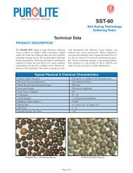
INTRODUCTIONIon exchange <strong>resins</strong> have been used to recover <strong>uranium</strong> since <strong>the</strong> 1950’s. The first generation of<strong>uranium</strong> mines in <strong>the</strong> western world used mainly fixed-bed ion exchange. During <strong>the</strong> 1970’s, severalcontinuous ion exchange processes were adopted, such as <strong>the</strong> Porter System (Rossing Uranium inNamibia) and <strong>the</strong> NimCIX (Vaal Reefs South in South Africa). These fluidised bed systems had asignificant advantage over fixed-bed systems in that <strong>the</strong>y could handle some solids, <strong>the</strong>rebydecreasing <strong>the</strong> need <strong>for</strong> perfect solid-liquid separation.The majority of operating <strong>uranium</strong> plants employ sulphuric acid leaching, followed by upgrading andpurification via ion exchange and/or solvent extraction, followed by final precipitation of yellow cake.Countries in <strong>the</strong> Former Soviet Union states have always been using RIP <strong>for</strong> <strong>the</strong> <strong>recovery</strong> of bothgold and <strong>uranium</strong>. The main advantage of RIP over fixed-bed and fluidised-bed operations is thatno solid-liquid separation is required, resulting in a major capital cost savings. Fur<strong>the</strong>rmore, it has<strong>the</strong> potential to combine <strong>the</strong> <strong>recovery</strong> and purification steps, resulting in fur<strong>the</strong>r cost savings. Thereis also <strong>the</strong> potential <strong>for</strong> improved <strong>recovery</strong> from ores that are difficult to settle and filter and wherewater balance issues prevent efficient washing. RIP allows <strong>the</strong> exploitation of low grade ore-bodiesthat may have been previously considered as uneconomical due to a simplified flowsheet andhigher recoveries.The use of RIP in <strong>the</strong> Western World <strong>for</strong> <strong>the</strong> <strong>recovery</strong> of <strong>uranium</strong>, gold and base metals is still verylimited. Numerous studies have been conducted, with very positive outcomes. However, <strong>the</strong>expected resin loss remains one of <strong>the</strong> major uncertainties. The resin loss that is experienced on aplant is not only dependent on <strong>the</strong> <strong>durability</strong> of <strong>the</strong> resin itself, but also on <strong>the</strong> plant design, nature of<strong>the</strong> ore and management of <strong>the</strong> resin inventory. Various plant designs exist, including air-agitatedpachucas and mechanically agitated tanks, arranged in ei<strong>the</strong>r carousel or continuous configuration.The manner in which resin is transferred between stages is also very important and designs includeairlifts, pumping and eductors. The geology of <strong>the</strong> orebody plays an important role, since <strong>uranium</strong>occurs in different types of minerals. Some ores are considered as harsh, especially siliceous oressuch as <strong>the</strong> Witwatersrand gold ores in South Africa. Higher resin losses can be expected <strong>for</strong> a RIPoperation on such ores. O<strong>the</strong>r ores have a higher clay content and will be less harsh on <strong>the</strong> resin.Resin suppliers have invested greatly to ensure <strong>the</strong> supply of improved products to <strong>the</strong> RIP market.In addition to confirming <strong>the</strong> chemical suitability of a product (loading and elution characteristics),<strong>the</strong> mechanical <strong>durability</strong> of products has to be tested. The overall suitability of a resin <strong>for</strong> a specificapplication has to be confirmed at an early stage of <strong>the</strong> project, since it is costly and impractical totest several <strong>resins</strong> on a large scale. For <strong>the</strong>se reasons, a lot of developmental work has been doneby resin manufacturers, test-laboratories and o<strong>the</strong>rs around <strong>the</strong> world in <strong>the</strong> quest <strong>for</strong> quick, easy,inexpensive and accurate tools to predict <strong>the</strong> resin-loss <strong>for</strong> a full-scale operation. Failing that, suchtools should at least provide a reliable manner of classifying different <strong>resins</strong>.METALLURGYA simplified flowsheet of a <strong>uranium</strong> RIP plant is shown in Figure 1. Leached pulp enters <strong>the</strong> plantvia <strong>the</strong> first contactor, from where it moves via gravity to <strong>the</strong> next reactors, until barren pulp leaves<strong>the</strong> plant from <strong>the</strong> last reactor. Fresh/eluted resin enters <strong>the</strong> plant via <strong>the</strong> last reactor and movescounter-currently to <strong>the</strong> pulp through <strong>the</strong> plant.Loaded resin from <strong>the</strong> first reactor is transferred to a dedicated elution column where it is contactedwith sulphuric acid. The <strong>uranium</strong>-rich eluate continues to fur<strong>the</strong>r purification via solvent extraction ordirectly to precipitation. Entrained acid and eluate is displaced through a waterwash, after which <strong>the</strong>eluted resin is returned to <strong>the</strong> last reactor of <strong>the</strong> adsorption section.2
Figure 1 Schematic representation of RIP circuitResin selection parametersThe desirable characteristics of an ion exchange resin vary according to <strong>the</strong> application [3] . In allcases, <strong>the</strong> general requirements are: High operating capacity; Efficient elution/regeneration; Service life <strong>durability</strong>.A high operating capacity refers to <strong>the</strong> maximum <strong>uranium</strong> loading that can be achieved. At <strong>the</strong>same time, <strong>the</strong> co-loading of impurities should be minimised.Efficient elution/regeneration includes <strong>the</strong> ability to use readily available and economical reagents toelute <strong>the</strong> valuable metal into a small volume, within a reasonable time, and to a low residual metalcontent.The focus of this document is <strong>the</strong> third characteristic, namely service life <strong>durability</strong>. The life of aresin can be reduced by various factors, both chemical and physical.Chemical factors include organic fouling, oxidation and osmotic shock. Resins, especially strongbase anion exchange <strong>resins</strong>, are prone to organic fouling. Such organics may originate from anumber of sources, e.g. <strong>the</strong> raw water used <strong>for</strong> dissolution of <strong>the</strong> <strong>uranium</strong>, <strong>the</strong> ore itself, oil-leaksfrom motors, and overdosing of certain chemicals upstream of <strong>the</strong> resin plant. Strong oxidants, suchas free chlorine, will attack <strong>the</strong> backbone of <strong>the</strong> resin, <strong>the</strong>reby decreasing <strong>the</strong> stability of <strong>the</strong> <strong>resins</strong>tructure.Osmotic shock, due to swelling and shrinking when exposed to acidic and alkalineconditions, weakens <strong>the</strong> backbone of a resin.However, breakage due to mechanical abrasion is <strong>the</strong> largest contributor to resin loss on a RIPplant, especially when combined with osmotic shock.Particle size distributionResins used in RIP applications need to be of “reasonable” size. Larger resin beads allow fasterseparation from pulp over inter-stage screens, but larger beads has slower diffusion-kinetics of<strong>uranium</strong>, from <strong>the</strong> PLS into <strong>the</strong> resin during extraction, and out of <strong>the</strong> resin during elution. Slowreaction kinetics requires larger plants or higher resin inventories, both resulting in higher capitalcost.3
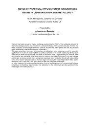
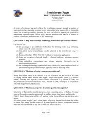
Large resin beads are more sensitive to osmotic shock, which is a result of swelling and shrinking of<strong>the</strong> resin when subjected to alternating acidic and alkaline conditions. Strong base <strong>resins</strong> typicallyswell 5-10% from <strong>the</strong> sulphate to hydroxide <strong>for</strong>ms.“Reasonable” is thus a compromise between <strong>the</strong> desire <strong>for</strong> fast kinetics of <strong>the</strong> loading/elutionreactions (small beads), good mechanical strength (small beads) and <strong>the</strong> desire <strong>for</strong> quickseparation from <strong>the</strong> pulp using large-aperture screens (large beads).Different applications require different types of ion exchange contactor designs. Resins are suppliedin different size-gradings, <strong>the</strong> choice of which depends on <strong>the</strong> contactor design. The differences areillustrated inFigure 2. For a “standard” grading, <strong>the</strong> size of <strong>the</strong> beads varies from 325 to 1180 µm, with <strong>the</strong>largest percentage being between 425 and 1000 µm. Modern fixed bed applications requires <strong>resins</strong>with a very narrow size distribution, e.g. 600-700 µm. RIP <strong>resins</strong> also have a narrow size distribution,but shifted to <strong>the</strong> right of <strong>the</strong> fixed-bed grade, with <strong>the</strong> majority or <strong>the</strong> resin beads being between850 and 1000 µm.Figure 2: Particle size distribution of different resin gradingsUranium ores are typically milled to 100% < 200 µm, with inter-stage screen-apertures set atbetween 400 and 600 µm. RIP grade <strong>resins</strong> typically have an average diameter of 850 to 1000 µm,with >90% of <strong>the</strong> resin having a size of 800-1300 µm. There is thus a diameter difference between<strong>the</strong> average resin bead and pulp particle of up to 600 µm.Resin loading capacityThe maximum <strong>uranium</strong> loading onto a resin that can be achieved is dependent on a number offactors, including <strong>the</strong> <strong>uranium</strong> concentration of <strong>the</strong> pregnant leach solution (PLS), possiblesuppression of <strong>uranium</strong> loading due to <strong>the</strong> presence of competing anions (e.g. vanadium, chlorides)or fouling of <strong>the</strong> resin, and contact time. Generating an equilibrium loading iso<strong>the</strong>rm, using asyn<strong>the</strong>tic solution, is a quick and simple way of comparing <strong>the</strong> per<strong>for</strong>mance of different <strong>resins</strong>.Mintek uses a syn<strong>the</strong>tic feed solution with a composition of 0.5 g/L U 3 O 8 , 1 g/L Fe 3+ and 20 g/LSO 4 2- , at pH 1.8. This solution is representative of a PLS expected from a typical acid leachoperation. Resin and solution are contacted in batch at different ratios <strong>for</strong> a period of 24 hours atambient temperature. After 24 hours, <strong>the</strong> resin and solution are separated and analysed.Freundlich iso<strong>the</strong>rms have been found to generally give a good fit to <strong>the</strong> data, as shown in Figure 3.The data clearly shows that higher <strong>uranium</strong> loadings can be achieved with Resin B, making thisresin more attractive, if judged purely on capacity.4
Figure 3: Equilibrium loading iso<strong>the</strong>rmElution characteristicsA suitable resin will be easy to elute, using readily available and inexpensive reagents, within areasonable time. Acid leach <strong>uranium</strong> operations typically use sulphuric acid as eluant. Stripping(elution) iso<strong>the</strong>rms <strong>for</strong> two different <strong>resins</strong> are shown inFigure 4, to illustrate <strong>the</strong> difference inbehaviour of two different <strong>resins</strong>.These iso<strong>the</strong>rms were generated by contacting pre-loaded resin and 110 g/L H 2 SO 4 in batch atdifferent resin-to-solution ratios <strong>for</strong> a period of 10 hours. After completion of <strong>the</strong> test, <strong>the</strong> resin andacid were separated and <strong>the</strong> <strong>uranium</strong> concentrations determined. The final acid concentrationswere ≥80 g/L, to ensure that stripping was not hampered by a lack of acid.Figure 4: Stripping iso<strong>the</strong>rmsThe stripping iso<strong>the</strong>rms <strong>for</strong> both <strong>resins</strong> were fairly flat, indicating that stripping is relativelyunfavourable, but low residual loadings were achieved on both <strong>resins</strong>, meaning that it should bepossible to achieve low barren concentrations when <strong>the</strong> resin is recycled to <strong>the</strong> adsorption circuit.5
Higher eluate concentrations were achieved with Resin Z. This is desirable, as it will reduce <strong>the</strong> sizeof <strong>the</strong> downstream purification/precipitation equipment, <strong>the</strong>reby reducing both <strong>the</strong> capital outlay andreagent cost.DURABILITYThe choice of resin <strong>for</strong> a RIP operation is not based on one single characteristic. It is ra<strong>the</strong>r acombination of high <strong>uranium</strong> loading capacity, low co-loading of impurities, ease of stripping usingreadily-available reagents, large particle size and, last, but certainly not least, mechanical strength.It is not practical to evaluate <strong>the</strong> strength of all <strong>resins</strong> with promising chemical characteristics(loading capacity and elution) on a large-scale continuous plant, due to cost and time limitations. Toovercome this problem, various laboratory-scale tests have been developed to evaluate <strong>the</strong> relativestrength of different <strong>resins</strong> and provide an indication of <strong>the</strong> resin loss that can be expected on a fullscaleplant.Laboratory scale <strong>durability</strong> testsBall Mill testsThe Russian Ball Mill (RBM) test is used by <strong>Purolite</strong> to confirm <strong>the</strong> physical strength of <strong>the</strong> resin. Apicture of <strong>the</strong> set-up is shown in Figure 5. The RBM parameter correlates to a specific resin lossexpected on operating plants. The ratio is based on multiple data points that have been collectedfrom a large number of (mainly gold) operations in <strong>the</strong> Former Soviet Union to which <strong>Purolite</strong> havebeen supplying resin since <strong>the</strong> 1980’s.Figure 5: Russian Ball Mill (used by <strong>Purolite</strong>)Mintek also per<strong>for</strong>ms a Ball Mill test [5] , using a planetary ball mill with a somewhat different design,as shown in Figure 6.6
Figure 6 Planetary ball mill (used by Mintek)Both mills work on <strong>the</strong> same principle, regardless of <strong>the</strong> details of <strong>the</strong> design. A known volume ofresin (pre-screened to >600 µm) is placed in a steel cylinder, toge<strong>the</strong>r with a grinding medium (a setnumber of steel or ceramic balls with known diameter) and a known volume of water. The cylinder isrotated at a set speed <strong>for</strong> a set time, after which <strong>the</strong> resin is separated from <strong>the</strong> grinding mediumand <strong>the</strong> remaining volume of resin beads with diameter >600 µm measured. The numbers are usedto express <strong>the</strong> strength of <strong>the</strong> resin:S = V 1 /V 2 x 100Where:S = mechanical strengthV 1 = volume of resin with; size >600 µm after milling;V 2 = initial volume of resin with size >600 µm.The ball mill test parameter cannot necessarily be used to predict <strong>the</strong> resin loss <strong>for</strong> all plants, due to<strong>the</strong> variations in plant design and ore characteristics that is found in different operations around <strong>the</strong>world. The conditions of <strong>the</strong> ball mill test are also much harsher than that experienced on an actualplant operation. Resin breakage occurs mainly during pumping and screening of <strong>resins</strong> and to alesser degree due to agitation and collision.The ball mill test does however remain a useful tool that is quick and inexpensive. It can be used tocompare <strong>resins</strong> and eliminate very poor per<strong>for</strong>ming <strong>resins</strong> at an early stage, be<strong>for</strong>e spending time,ef<strong>for</strong>t and money on piloting of weak <strong>resins</strong>.Flotation cell testsA Denver Flotation Cell, as shown in Figure 7, is ano<strong>the</strong>r method used to test resin <strong>durability</strong> [9] .During this test, <strong>the</strong> resin is subjected to both osmotic shock (caused by swelling and shrinking of<strong>the</strong> resin during pH swings between acidic and alkaline conditions) and mechanical abrasion.7
Figure 7 Denver flotation cellThe resin, pre-screened to >600 µm, is stirred in <strong>the</strong> Denver flotation cell <strong>for</strong> 60 minutes at 1500rpm. Sand may be added, to simulate <strong>the</strong> abrasive environment provided by pulp. Upon completion,<strong>the</strong> resin is separated from <strong>the</strong> water and/or sand and transferred to a column where it is subjectedto alkaline and acid treatments. Alkaline treatment consists of 3 bedvolumes (a bedvolume is <strong>the</strong>volume of solution equal to <strong>the</strong> volume of resin in <strong>the</strong> test) of a 2 mol/L NaOH solution, followed bya waterwash to remove excess caustic. The resin is <strong>the</strong>n contacted with 3 bedvolumes of 2 mol/LH 2 SO 4 , followed by a waterwash to remove excess acid. One cycle consists of three distinct steps,i.e. (1) stirring in <strong>the</strong> flotation cell, (2) alkaline treatment, and (3) acid treatment. The resin volume ismeasured after each cycle and <strong>the</strong> relative loss, as a percentage of <strong>the</strong> volume at <strong>the</strong> beginning of<strong>the</strong> cycle, is calculated. Several cycles (at least 5) are required <strong>for</strong> a proper comparison. This testprovides a good indication of <strong>the</strong> relative strength of different <strong>resins</strong>, but is ra<strong>the</strong>r cumbersome andtime-consuming.The cumulative loss per cycle <strong>for</strong> four different <strong>resins</strong> [2] is compared graphically in Figure 8. Theresults show that <strong>the</strong> highest loss over 5 cycles was obtained with GT2, while <strong>the</strong> lowest loss wasseen <strong>for</strong> GT1.Figure 8 Cumulative loss of different <strong>resins</strong>, Denver flotation cell8
Compression testsCompression testing [5] is used to determine <strong>the</strong> resin behaviour under load and <strong>the</strong> maximumstress <strong>the</strong> resin can sustain <strong>for</strong> <strong>the</strong> duration of <strong>the</strong> load (constant or progressive). It gives anindication of <strong>the</strong> elasticity and plasticity characteristics of <strong>the</strong> <strong>resins</strong> as well as <strong>the</strong> point of transitionbetween <strong>the</strong>se two states. The elasticity region is <strong>the</strong> range of applied load in which <strong>the</strong> resin bead returns to its initial<strong>for</strong>m upon removal of <strong>the</strong> load. The slope of <strong>the</strong> curve in this region is termed <strong>the</strong> Young’sModulus. In <strong>the</strong> plasticity region, permanent de<strong>for</strong>mation (cracking) has occurred and <strong>the</strong> resin beaddoes not completely return to its initial <strong>for</strong>m upon removal of <strong>the</strong> load. Fracture is <strong>the</strong> point of irreversible de<strong>for</strong>mation. At this point, compressive <strong>for</strong>ces aregreater than internal inter-molecular <strong>for</strong>ces and are sufficient to cause cracking of <strong>the</strong> bead.The applied load at <strong>the</strong> point of fracture is termed <strong>the</strong> Break Load.A picture of <strong>the</strong> LF Plus Materials Testing Machine is shown in Figure 9.Figure 9 Compression test machineResin beads (100 beads per test) with a diameter of 850 µm are tested. Individual resin beads areplaced on <strong>the</strong> compression plate and encircled with water. The compression plate is <strong>the</strong>n loweredslowly until it contacts <strong>the</strong> resin bead, after which compression of <strong>the</strong> bead is done at a constantspeed of 0.5 mm/minute and <strong>for</strong>ce of 0.5 N. The compression is automatically stopped once afracture within <strong>the</strong> resin bead is detected. A typical stress-strain curve <strong>for</strong> <strong>the</strong> <strong>for</strong>ce applied on amaterial is shown in Figure 10. The applied load is plotted against <strong>the</strong> percentage strain that a resinundergoes. The strain is an indication of <strong>the</strong> de<strong>for</strong>mation relative to <strong>the</strong> initial diameter of <strong>the</strong> resin(in this case 850 µm).9
Figure 10 Diagram of a stress-strain curve, showing <strong>the</strong> relationship between stress (<strong>for</strong>ceapplied) and strain (de<strong>for</strong>mation) of a ductile materialThe variation in characteristics of three different <strong>resins</strong> is illustrated by <strong>the</strong> data in Table 1 andFigure 11.Table 1 Compression test data <strong>for</strong> 3 different <strong>resins</strong>Resin D Resin E Resin FYoung’s Modulus (slope of first linear portion) 0.052 0.082 0.132Break load, N 1.4 4.4 5.3Break load, % Strain 18 33 28Figure 11 Compression test: Load vs % strain10
Based on <strong>the</strong>se results, Resin F can be classified as <strong>the</strong> strongest of <strong>the</strong> three <strong>resins</strong>. It had <strong>the</strong>highest Young’s Modulus, meaning that it could withstand <strong>the</strong> highest load be<strong>for</strong>e permanentde<strong>for</strong>mation, i.e. it was <strong>the</strong> most elastic. Resin F was also able to withstand <strong>the</strong> highest load be<strong>for</strong>ebreaking. Resin D was <strong>the</strong> weakest of <strong>the</strong> three <strong>resins</strong>.Too much elasticity is also not desirable, since a highly elastic resin may squeeze through <strong>the</strong>apertures in a screen and cause blockages. Exactly how much elasticity is required is still underinvestigation.This type of test provides in<strong>for</strong>mation on a number of aspects of <strong>the</strong> physical strength of a resin.Due to <strong>the</strong> automated nature of <strong>the</strong> test, it is quite independent of operator-skills. However, a largenumber of resin beads has to be tested to obtain a reasonable average and interpretation of <strong>the</strong>results requires skills and experience.Mechanical agitationThe results of investigations into <strong>the</strong> optimum conditions of mechanical agitation have beenpublished by Mixtec [2] . The aim of mixing <strong>the</strong> pulp-resin slurry is to ensure a uni<strong>for</strong>m distribution of<strong>the</strong> resin and <strong>the</strong> solids in <strong>the</strong> pulp, allowing maximum <strong>uranium</strong> extraction and minimum resinbreakage. In RIP, <strong>the</strong>re are two different systems that must be catered <strong>for</strong>. The fast-settling slurriesrequire a high degree of agitation at <strong>the</strong> bottom of <strong>the</strong> tank to provide uni<strong>for</strong>m suspension. Buoyantresin needs good surface movement to draw it into <strong>the</strong> pulp. Typical mixing practice is to employlow-shear high-flow hydrofoil impellers. Mixtec’s special impeller geometry consisted of a large ratiodown pumping impeller to suspend <strong>the</strong> solids and a smaller up-pumping impeller to draw in <strong>the</strong>resin. This configuration was tested in tanks with diameters varying from 300 mm to 1200 mm.It was found that resin loss increased with a decrease in tank diameter, from ~4% in <strong>the</strong> largestdiameter tank to 70% in <strong>the</strong> smallest tank. This was ascribed to <strong>the</strong> fact that <strong>the</strong> impeller and o<strong>the</strong>rfactors were scaled down in <strong>the</strong> smaller tank, but <strong>the</strong> resin particles remained <strong>the</strong> same, resulting ina higher collision rate and impact, causing higher resin losses.This type of test is useful to provide in<strong>for</strong>mation on <strong>the</strong> effect of agitation and agitator design onresin breakage. Since agitation is only one of <strong>the</strong> aspects that may cause resin breakage, this testcan be used to compare <strong>the</strong> relative strength of different <strong>resins</strong>, but cannot be used in isolation topredict resin losses.Effect of silicaSilica fouling of strong base anion exchange <strong>resins</strong> during <strong>the</strong> <strong>recovery</strong> of <strong>uranium</strong> from acid-leachliquors is a well-known problem [8,10] . Recent investigations have shown that silica fouling mainlyoccurs on <strong>the</strong> outer rim of <strong>the</strong> resin beads, <strong>the</strong>reby inhibiting <strong>the</strong> free diffusion of <strong>uranium</strong> in and outof <strong>the</strong> resin during <strong>the</strong> adsorption and elution steps. If left untreated, <strong>the</strong> level of silica increasesthroughout <strong>the</strong> resin bead, severely affecting <strong>the</strong> metallurgical per<strong>for</strong>mance of <strong>the</strong> resin. Removal ofsilica via periodic treatment with caustic soda (NaOH) is required to restore <strong>the</strong> resin’s operatingcapacity <strong>for</strong> <strong>the</strong> adsorption of valuable metal. The resin on an acid-leach <strong>uranium</strong> plant is subjectedto significant osmotic shock, as it is subjected to strongly acidic conditions during elution (110 g/LH 2 SO 4 ) as well as strongly alkaline conditions during caustic treatment to remove silica. Theresulting swelling and shrinking weakens <strong>the</strong> resin, making it more prone to degradation.Interestingly enough, some improvement in resin strength was observed <strong>for</strong> silica fouled <strong>resins</strong>during laboratory tests. It has however also been found that higher silica levels makes <strong>the</strong> resinmore brittle.It is not expected that <strong>the</strong> presence of silica will have a significant effect on resin degradation,provided silica fouling is handled appropriately.Large-scale <strong>durability</strong> tests and pilot plantMintek and Bateman Engineering ran a demonstration plant <strong>for</strong> Harmony Gold at one of <strong>the</strong>ir goldmining operations in South Africa in 2010 [1,4] . The plant comprised of an acid-leach circuit, <strong>the</strong>Mintek/Bateman developed MetRIX continuous RIP plant, as well as an elution and tailingstreatment circuit. The demonstration plant was operated <strong>for</strong> 47 days.11
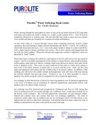
In addition to evaluating various mechanical aspects of <strong>the</strong> plant, <strong>the</strong> degradation and volume lossof resin were closely monitored. Fresh resin, as well as resin that had been abraded during <strong>the</strong> RIPpiloting, are shown in Figure 12 (fresh) and Figure 13 (abraded). The pictures shows that <strong>the</strong> resinused during <strong>the</strong> demonstration plant fractured into irregular pieces. Resin loss is ascribed to <strong>the</strong>loss of any pieces that are smaller than <strong>the</strong> aperture of <strong>the</strong> screens used to separate resin and pulp.Figure 12 Resins viewed under a microscope, freshFigure 13 Resins viewed under a microscope, showing <strong>the</strong> effect of abrasionFINANCIAL EFFECT OF RESIN LOSSTechno-economic evaluations have been done on various flowsheet configurations. A recent studyby Bateman [6] found that <strong>the</strong> optimum flowsheet can be largely based on <strong>the</strong> <strong>uranium</strong> grade of <strong>the</strong>ore. At <strong>uranium</strong> concentrations of less than 900 mg/L U 3 O 8 , a processing route comprising RIP <strong>for</strong>bulk <strong>uranium</strong> <strong>recovery</strong>, followed by solvent extraction (SX) <strong>for</strong> purification, was found to be <strong>the</strong> mosteconomical (RIP-SX). At higher <strong>uranium</strong> concentrations (>900 mg/L U 3 O 8 ), <strong>the</strong> most economicalroute would consist of counter-current decantation (CCD) followed by SX <strong>for</strong> <strong>uranium</strong> upgrading andpurification (CCD-SX).12
The Bateman study also investigated <strong>the</strong> effect of various parameters, such as resin loss, on <strong>the</strong>Operating Cost (Opex) of a project. The resin loss assumption was based on results ofdemonstration-scale <strong>durability</strong> trials. The study found that <strong>the</strong> Opex was relatively insensitive tovariations in resin loss. The annual resin loss was found to constitute
REFERENCES1. Auerswald, D., Udayar, T. Kotze, M.H., Scheepers, J. (2011) Operation of a resin-in-pulpplant <strong>for</strong> recovering <strong>uranium</strong> from a South African gold pulp. Alta 2011 Uranium Conference.Alta Metallurgical Services. Australia.2. Baguley, W. (2009) The agitation of <strong>uranium</strong> leach and resin-in-pulp applications. Alta 2009Uranium Conference. Alta Metallurgical Services. Australia.3. Mikhaylenko, M, van Deventer, J. (2009) Notes of practical application of ion exchange<strong>resins</strong> in <strong>uranium</strong> extractive metallurgy. Alta 2009 Uranium Conference. Alta MetallurgicalServices. Australia.4. Udayar, T., Kotze, M.H., Yahorava, V. (2011) Recovery of <strong>uranium</strong> from dense slurries viaresin-in-pulp. The Sou<strong>the</strong>rn African Institute of Mining and Metallurgy, <strong>the</strong> Sixth Sou<strong>the</strong>rnAfrican Base Metal Conference.5. Udayar, T, Shange, Z, Kotze, MH, Yahorova, Y (2012) Durability of ion exchange <strong>resins</strong> <strong>for</strong><strong>the</strong> <strong>recovery</strong> of <strong>uranium</strong> via resin-in-pulp. The International Ion Exchange Conference (IEX2012), 19-21 September 2012, Queens’ College Cambridge, United Kingdom.6. Van Tonder, D., Van Hege, B. (2007) Uranium <strong>recovery</strong> from acid leach liquors: Theoptimisation of RIP/SX based flowsheets. The Sou<strong>the</strong>rn African Institute of Mining andMetallurgy, <strong>the</strong> Fourth Sou<strong>the</strong>rn African Conference on base metals, pp 17-39.7. Yahorova, V, Scheepers, J, Kotze, MH (2009) Comparison of various anion exchange<strong>resins</strong> <strong>for</strong> <strong>the</strong> <strong>recovery</strong> of <strong>uranium</strong> by means of RIP. Alta 2009 Uranium Conference. AltaMetallurgical Services. Australia.8. Yahorava, V., Scheepers, J., Kotze, M.H. (2009) Impact of silica on hydrometallurgical andmechanical properties of RIP grade <strong>resins</strong> <strong>for</strong> <strong>uranium</strong> <strong>recovery</strong>. The South African Instituteof Mining and Metallurgy, Mintek 75 Anniversary.9. Yahorava, V., Scheepers, J., Kotze, M.H. (2009) Evaluation of various <strong>durability</strong> tests toassess <strong>resins</strong> <strong>for</strong> in-pulp applications. The Sou<strong>the</strong>rn African Institute of Mining andMetallurgy base Metals Conference.10. Zaganiaris, E.J.(1981) Effect of physical and chemical structure of ion exchange resin onsilica fouling in acid leach liquors in <strong>uranium</strong> hydrometallurgy. Hydrometallurgy 81,Manchester England.14