200 Series Professional VHF Wireless Systems - Audio-Technica
200 Series Professional VHF Wireless Systems - Audio-Technica
200 Series Professional VHF Wireless Systems - Audio-Technica

Create successful ePaper yourself
Turn your PDF publications into a flip-book with our unique Google optimized e-Paper software.
<strong>200</strong> <strong>Series</strong> <strong>Professional</strong><strong>VHF</strong> <strong>Wireless</strong> <strong>Systems</strong>ATW-251 UniPak ® Transmitter SystemATW-251/G Guitar SystemATW-251/H Headworn Microphone SystemATW-251/H92 Headworn Microphone SystemATW-251/H92-TH Headworn Microphone SystemATW-251/L Lavalier Microphone SystemATW-252 Handheld Microphone SystemInstallation and Operation
<strong>Professional</strong> <strong>VHF</strong> <strong>Wireless</strong> <strong>Systems</strong>Installation and OperationThis device complies with part 15 of the FCC Rules.Operation is subject to the condition that this device doesnot cause harmful interference.This device complies with INDUSTRY CANADA R.S.S. 210,en conformité avec IC: RSS-210/CNR210. Operation is subjectto the following conditions: 1) This device may notcause harmful interference and 2) this device must acceptany interference received, including interference whichmay cause undesired operation. Changes ormodifications not expressly approved by <strong>Audio</strong>-<strong>Technica</strong>could void your authority to operate this equipment.CAUTION! Electrical shock can result from removal ofthe receiver cover. Refer servicing to qualified servicepersonnel. No user-serviceable parts inside. Do notexpose to rain or moisture.The circuits inside the receiver and transmitter have beenprecisely adjusted for optimum performance and compliancewith federal regulations. Do not attempt to open thereceiver or transmitter. To do so will void the warranty,and may cause improper operation.Notice to individuals with implanted cardiac pacemakersor AICD devices:Any source of RF (radio frequency) energy may interfere withnormal functioning of the implanted device. All wirelessmicrophones have low-power transmitters (less than 0.05watts output) which are unlikely to cause difficulty, especiallyif they are at least a few inches away. However, since a “bodypack”mic transmitter typically is placed against the body, wesuggest attaching it at the belt, rather than in a shirt pocketwhere it may be immediately adjacent to the medical device.Note also that any medical-device disruption will cease whenthe RF transmitting source is turned off. Please contact yourphysician or medical-device provider if you have any questions,or experience any problems with the use of this or any otherRF equipment.IntroductionThank you for choosing an <strong>Audio</strong>-<strong>Technica</strong> professional wirelesssystem. You have joined thousands of other satisfied customerswho have chosen our products because of their quality,performance and reliability. This wireless microphone systemis the successful result of years of design and manufacturingexperience.Each <strong>200</strong> <strong>Series</strong> professional <strong>VHF</strong> wireless system includes areceiver and either a body-pack transmitter or a handheldmicrophone/transmitter on a specific crystal-controlledfrequency. ATW-251 UniPak ® body-pack transmitter systemsinclude models pre-packaged with either an AT-GCW guitarcable (/G), a PRO 8HEcW headworn microphone (/H), aPRO 92cW headworn microphone (/H92), a PRO 92cW-THheadworn microphone (/H92-TH), or a lavalier mic (/L) forparticular applications. All A-T <strong>Wireless</strong> Essentials ® microphonesand cables, available separately, are pre-terminated for use withany ATW-251 system.Because <strong>200</strong> <strong>Series</strong> packaging is designed to hold all versionsof the system, some compartments in the carton areintentionally left empty.The ATW-R250 receiver includes a space-saving switchingpower supply that automatically adapts to changes in mainsvoltage. Unlike bulky linear power supplies, this switching powersupply is lightweight and compact; it uses only a single outletspace.The versatile ATW-T201 UniPak body-pack transmitter has botha high-impedance input for instruments, and a low-impedanceinput with bias connection for use with dynamic and electretcondenser microphones. The ATW-T202 handheld transmitterfeatures a unidirectional dynamic microphone element.Both the body-pack and handheld transmitters use internal9-volt batteries and have Off/Standby/On switches, input Trim(level) adjustments and battery-save switches.2See pages 8-9 for illustrations.
Receiver InstallationLocationFor best operation the receiver should be at least 3' (1 m)above the ground and at least 3' (1 m) away from a wall ormetal surface to minimize reflections. Keep the receiverantennas away from noise sources such as digital equipment,motors, automobiles and neon lights, as well as away fromlarge metal objects. In multi-channel systems, positionreceivers at least 3' (1 m) apart and keep operatingtransmitters at least 6' (2 m) from the receivers to help assuremaximum RF performance.Output ConnectionThe receiver provides unbalanced, aux-level output from a 1 /4"TS (“mono”) phone jack; an output cable is not included. Usea shielded audio cable with 1 /4" phone plug to connect thereceiver’s AF Out jack to the mixer/amplifier’s aux-level input.AntennasA novel “dipole” antenna system on the receiver improvesoperation by providing a “ground” element in addition to theusual “signal” element. Position the two antennas at 90° in theform of a “V,” or position the left (“signal”) antenna verticallyand the right (“ground”) antenna horizontally, in the shape ofan “L” (Fig. A). Use the position that performs better in youroperating environment. Be certain to extend both antennas totheir full 15" (38 cm) length by holding them at their bases andpulling out on their caps. Both antenna elements may beswiveled to the left and right, but do not attempt to rotate themin a screwing/unscrewing motion. To do so may damage theantenna and/or receiver. For best performance, locate thereceiver so its antennas are in direct line-of-sight to thetransmitter's likely operating position.Power ConnectionConnect the DC plug on the included AC power adapter to theDC power input on the back of the receiver. Secure the cordover the cord hook on the back of the receiver, to keep theplug from being detached by an accidental tug on the cord.Then plug the adapter into a standard 120 Volt 60 Hz AC poweroutlet.(Note that the receiver has no power Off/On switch. Thereceiver will be energized whenever the power adapter isconnected and plugged into the AC outlet. Unplug the powersupply from the AC outlet when the system is not in use –both for safety, and to conserve energy.)Receiver Controls and FunctionsFront Panel Controls and Functions (Fig. B)1. ANTENNAS: Position the “signal” antenna (1a) and“ground” antenna (1b) as shown in Figure A.2. POWER INDICATOR: Lights when power is supplied tothe receiver.3. RF INDICATOR: Lights to show presence of transmittersignal.4. AF PEAK INDICATOR: Only lights when audio distortionis present at maximum modulation. Not affected byposition of Volume control.Rear Panel Controls and Functions (Fig. C)5. AUDIO OUTPUT JACK: 1 /4" TS (Tip-Sleeve) or “mono”phone jack. Use a shielded cable to connect to anunbalanced aux-level input of a mixer or amplifier.6. VOLUME CONTROL: Adjusts the audio level at the 1 /4"output jack. Does not affect AF Peak indicator.7. CORD HOOK: Loop the cord around the cord hook to keepthe DC plug from pulling out accidentally.8. POWER INPUT JACK: Connect the DC plug from theincluded AC adapter.3
Transmitter SetupBattery Selection and InstallationAn alkaline 9-volt battery is recommended. Make certain thetransmitter power switch is Off before installing or changingbatteries.When inserting the battery, observe correct polarity asmarked inside the battery compartment. The transmitterhousings are designed to prevent incorrect installation of thebattery; do not force the battery in. Reversed batteries maycause damage to the transmitter.UniPak ® Transmitter Battery Installation1. Slide off the battery cover as shown in Figure D.2. Carefully insert a fresh 9V alkaline battery, observing polaritymarkings.3. Replace the battery cover (Fig. E).Handheld Transmitter Battery Installation1. While holding the upper part of the transmitter body justbelow the ball-screen, unscrew the lower body cover andslide it downward to expose the battery compartment(Fig. F). Do not attempt to pull the lower body fartherdown, or to gain access to the electronics.UniPak ® Transmitter Input ConnectionConnect an audio input device (microphone or guitar cable) tothe input connector on the bottom of the transmitter. Thecable connector latches automatically when inserted into thetransmitter jack. To unlatch and remove the connector, simplypull up on the connector’s knurled metal collar.A number of <strong>Audio</strong>-<strong>Technica</strong> professional microphones andcables are available separately, pre-terminated with a UniPakinput connector (see www.audio-technica.com).Transmitting AntennaThe UniPak transmitter includes a permanently attached flexibleantenna. For best results, allow the antenna to hang freely andfull length from the bottom of the transmitter. If the receivedsignal is marginal, experiment with different transmitterpositions on your body or instrument; or try repositioning thereceiver. Do not attempt to remove, replace or change thelength of the transmitting antenna.2. Lift the white “battery keeper” arm until it sticks straight outfrom the mic body (no higher). Then carefully insert a fresh9V alkaline battery, observing polarity markings.3. Screw the body back together. Do not overtighten.Battery Condition IndicatorThe red battery condition indicator (Fig. H/I) should light stronglywith a fresh battery. As the battery weakens, the indicator willgrow dimmer. When the indicator becomes very dim or goesout, there is little life left in the battery. Replace it at once forcontinued operation of the transmitter.All transmitters feature battery-save switches (Fig. D/F). Assupplied, the switch is set in the High position for maximumrange. Switching to the Low position increases battery life byreducing power. (Note: Effective range decreases when theswitch is set in Low position.)4See pages 8-9 for illustrations.
System OperationTurn down the receiver volume control and the mixer/amplifierlevel before starting up the wireless system. Do not switch onthe transmitter yet.Receiver on...Plug the power supply into an AC power source. The greenPower indicator on the front panel will light.Transmitter on...When the transmitter is switched on, the receiver’s yellow RFsignal indicator will light. The transmitters have a 3-positionpower switch. When the switch is set to “Standby” (ST orST.BY), the transmitter produces RF with no audio signal. Whenthe switch is “On,” the transmitter produces both RF and audio.Excessive audio input to the transmitter will cause the receiver’sred AF Peak indicator to light.Receiver VolumeUnder typical operating conditions, the receiver's volumecontrol should be turned all the way up, with overall systemaudio gain adjusted at the mixer or amplifier.Input Level AdjustmentInput trimmer controls in the transmitters enable you tomaximize performance for a particular microphone or guitarsensitivity, or to adjust for different acoustic input levels.Adjusting Input Level - UniPak TransmitterSlide the battery cover off the top part of transmitter andremove the screwdriver from its clip (Fig. D). Gently turn boththe “MT” (Mic Trimmer) and “GT” (Guitar Trimmer) controls totheir full counterclockwise positions (toward “LO”).• Microphone: Adjusting input levelGently turn only the “MT” (Mic Trimmer) control all the wayup (clockwise, toward “Hi”). Check for excessive gain by speaking/singinginto the microphone at typically loud levels whilewatching the receiver’s AF Peak indicator. If the AF Peak indicatordoes light, turn the MT control slightly counterclockwiseuntil the AF Peak indicator no longer lights with maximum audioinput to the transmitter.• Guitar/Instrument: Adjusting input levelGently turn only the “GT” (Guitar Trimmer) control all the wayup (clockwise, toward “Hi”). Check for excessive gain byplaying at typically loud levels while watching the receiver’s AFPeak indicator. If the AF Peak indicator does light, turn the GTcontrol slightly counterclockwise until the AF Peak indicator nolonger lights with maximum instrument input to the transmitter.After adjusting input level, return the screwdriver to its clipand reinstall the battery cover. No further transmitter gainadjustments should be needed, as long as the input deviceand the acoustic input level are not changed.Adjusting Input Level - Handheld TransmitterUnscrew the lower body cover and slide it downward, exposingthe screwdriver and Gain Trimmer control (Fig. G). Remove thescrewdriver from its clip. Gently turn the control to its fullclockwise position (toward the side marked “H”), the factorysetting. Check for excessive gain by speaking/singing into themicrophone at typically-loud levels while watching the receiver’sAF Peak indicator. If the AF Peak indicator does light, turn theGain Trimmer control slightly counterclockwise until the AF Peakindicator no longer lights with maximum audio input to themic/transmitter.Return the screwdriver to its clip and close and secure thelower body. No further transmitter gain adjustments shouldbe needed, as long as the acoustic input does not changesignificantly.CAUTION! The small trimmer controls are delicate; useonly the supplied screwdriver. Do not force the trimmersbeyond their normal 190 o range of rotation.Return the screwdriver to its storage clip when not in use.Ten Tips To Obtain The Best Results1. Use only fresh alkaline batteries. Do not use “general purpose”(carbon-zinc) batteries.2. Position the receiver so that it has the fewest possibleobstructions between it and the normal location of the transmitter.Line-of-sight is best.3. The transmitter and the receiver should be as close together asconveniently possible, but not less than 6' (2 m).4. Do not place the receiver antennas within 3' (1 m) of anotherreceiver or antenna.5. The receiver antennas should be kept away from any metal.6. A receiver cannot receive signals from two transmitters at thesame time.7. In the UniPak transmitter, the “MT” or “GT” input control notin use should be set to minimum.8. If the receiver output is set too low, the overall signal-to-noise ratioof the system may be reduced. Conversely, if the volume controlof the receiver is set too high, it may over-drive the input of themixer/amplifier, causing distortion. Adjust the output level of thereceiver so the highest sound pressure level going into themicrophone (or the loudest instrument playing level) causes noinput overload in the mixer, and yet permits the mixer levelcontrols to operate in their “normal” range (not set too high ortoo low). This provides the optimum signal-to-noise for theentire system.9. Turn the transmitter off when not in use. Remove the battery ifthe transmitter is not to be used for a period of time.10. Unplug the receiver from the AC outlet when the system is notin use.5
System Operating FrequenciesFrequency SelectionEach transmitter/receiver system operates on a single factoryaligned, crystal-controlled frequency. Available frequencies areshown in the chart below.Operating frequency is specified by a two character code,such as “T2,” in addition to the actual frequency in MHz. The frequencyof each transmitter appears on a label on the outside ofthe unit. The frequency of each receiver appears on a label onthe rear panel of the unit and the frequency of each systemappears on the outer carton. For future reference, please recordthem in the space provided below.RF InterferencePlease note that wireless frequencies are shared with otherradio services. According to Federal CommunicationsCommission regulations, “<strong>Wireless</strong> microphone operations areunprotected from interference from other licensed operationswithin the band. If any interference is received by anyGovernment or non-Government operation, the wirelessmicrophone must cease operation...”If you need assistance with operation or frequency selection,please contact your dealer or the A-T professional division.Extensive wireless information also is available on the A-T Website at www.audio-technica.com.Application Freq. Code Freq. (MHz)• Traveling frequencies: T2 169.505(Normally work anywhere in the U.S.A. and T3 170.245Canada.) T8 171.905<strong>Systems</strong> on these frequencies may be combined for up to three simultaneousoperating channels.For future reference, please record your system information here (the serial numbersappear near the screwdriver clip in each transmitter, and on the bottom ofeach receiver):Operating FrequencyFreq. Code Frequency • MHzReceiverModel ATW-R250Serial NumberTransmitterModel ATW-T201/2Serial Number6
Specifications †OVERALL SYSTEMOperating Frequency<strong>VHF</strong> high band, 169 MHz to 172 MHzFrequency Stability ±0.005%Modulation ModeFMMaximum Deviation±15 kHzOperating Range<strong>200</strong>' typicalOperating Temperature Range 40° F (4° C) to 110° F (43° C)Frequency Response80 Hz to 13 kHzRECEIVERReceiving SystemImage RejectionSignal-to-noise RatioTotal Harmonic DistortionSensitivity<strong>Audio</strong> OutputOutput ConnectorPower SupplyDimensionsNet WeightAccessories IncludedNon-diversity, single-channel,dual antenna system50 dB minimum80 dB at 10 kHz deviation (IEC-weighted),maximum modulation 15 kHz≤1% (10 kHz deviation at 1 kHz)20 dBµV for 60 dB S/N (IEC-weighted)350 mV (1 kHz modulation, 10 kHzdeviation, 100k ohm load)1/4" TS (“mono”) phone jack100-240V AC (50/60 Hz) to 12V DC 1A(center positive) switched mode externalpower supply7.48" (190.0 mm) W x 1.65" (42.0 mm) H x5.12" (130.0 mm) D11.0 oz (311 grams)Power supplyUNIPAK ® TRANSMITTERRF Power OutputSpurious EmissionsDynamic RangeInput ConnectionsBattery (not included)Current ConsumptionBattery LifeDimensionsNet Weight (without battery)HANDHELD TRANSMITTERRF Power OutputSpurious EmissionsDynamic RangeMicrophone ElementBattery (not included)Current ConsumptionBattery LifeDimensionsNet Weight (without battery)Accessory IncludedHigh: 10 mW; Low: 2 mW, typicalUnder Federal Regulations≥90 dB, A-weightedHigh impedance, low impedance, bias9V (NEDA type 1604) alkaline30 mA typicalApproximately 15 hours (High);20 hours (Low), depending on battery typeand use pattern2.56" (65.0 mm) W x 4.33" (110.0 mm) Hx 1.00" (25.4 mm) D2.8 oz (78 grams)High: 10 mW; Low: 2 mW, typicalUnder Federal Regulations≥90 dB, A-weightedDynamic unidirectional9V (NEDA type 1604) alkaline30 mA typicalApproximately 15 hours (High);20 hours (Low), depending on battery typeand use pattern9.50" (241.3 mm) long, 2.10" (53.3 mm)maximum diameter12.7 oz (360 grams)AT8456a Quiet-Flex stand clamp†In the interest of standards development, A.T.U.S. offers full details on its test methods toother industry professionals on request.7
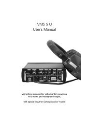
AntennasFigure A (p. 3)Receiver Controls and FunctionsFigure B - Front panel controls and functions1a2 3 41bFigure C - Rear panel controls and functions5 67 88
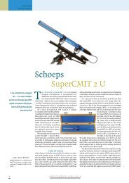
Transmitter Controls and FunctionsMicrophoneTrimmer (MT)Guitar Trimmer(GT)➞➞Figure DBattery-Save Switch(under screwdriver clip)Battery PolarityDiagramFigure EBattery PolarityDiagramBattery-SaveSwitchFigure FGain TrimmerFigure GScrewdriverPower SwitchOff/Standby/OnBattery ConditionIndicatorBattery ConditionIndicatorInputConnectorFigure HAntennaFigure IPower SwitchOn/Standby/Off9
<strong>Audio</strong>-<strong>Technica</strong> U.S., Inc., 1221 Commerce Drive, Stow, Ohio 44224 330/686-2600 www.audio-technica.comP51858-01 ©2011 <strong>Audio</strong>-<strong>Technica</strong> U.S., Inc. Printed in U.S.A.