NXP LPC2364, LPC2366, LPC2368 Data Sheet - Keil
NXP LPC2364, LPC2366, LPC2368 Data Sheet - Keil
NXP LPC2364, LPC2366, LPC2368 Data Sheet - Keil

Create successful ePaper yourself
Turn your PDF publications into a flip-book with our unique Google optimized e-Paper software.
<strong>LPC2364</strong>/66/68Single-chip 16-bit/32-bit microcontrollers; up to 512 kB flashwith ISP/IAP, Ethernet, USB 2.0, CAN, and 10-bit ADC/DACRev. 01 — 31 October 2006Preliminary data sheet1. General descriptionThe <strong>LPC2364</strong>/66/68 microcontrollers are based on a 16-bit/32-bit ARM7TDMI-S CPU withreal-time emulation that combines the microcontroller with up to 512 kB of embeddedhigh-speed flash memory. A 128-bit wide memory interface and a unique acceleratorarchitecture enable 32-bit code execution at the maximum clock rate. For criticalperformance in interrupt service routines and DSP algorithms, this increases performanceup to 30 % over Thumb mode. For critical code size applications, the alternative 16-bitThumb mode reduces code by more than 30 % with minimal performance penalty.The <strong>LPC2364</strong>/66/68 are ideal for multi-purpose serial communication applications. Theyincorporate a 10/100 Ethernet Media Access Controller (MAC), USB full speed devicewith 4 kB of endpoint RAM, four UARTs, two CAN channels, an SPI interface, twoSynchronous Serial Ports (SSP), three I 2 C interfaces, and an I 2 S interface. This blend ofserial communications interfaces combined with an on-chip 4 MHz internal oscillator,SRAM of up to 32 kB, 16 kB SRAM for Ethernet, 8 kB SRAM for USB and generalpurpose use, together with 2 kB battery powered SRAM make these devices very wellsuited for communication gateways and protocol converters. Various 32-bit timers, animproved 10-bit ADC, 10-bit DAC, one PWM unit, a CAN control unit, and up to 70 fastGPIO lines with up to 12 edge or level sensitive external interrupt pins make thesemicrocontrollers particularly suitable for industrial control and medical systems.2. Features• ARM7TDMI-S processor, running at up to 72 MHz.• Up to 512 kB on-chip flash program memory with In-System Programming (ISP) andIn-Application Programming (IAP) capabilities. Flash program memory is on the ARMlocal bus for high performance CPU access.• 8/32 kB of SRAM on the ARM local bus for high performance CPU access.• 16 kB SRAM for Ethernet interface. Can also be used as general purpose SRAM.• 8 kB SRAM for general purpose DMA use also accessible by the USB.• Dual Advanced High-performance Bus (AHB) system that provides for simultaneousEthernet DMA, USB DMA, and program execution from on-chip flash with nocontention between those functions. A bus bridge allows the Ethernet DMA to accessthe other AHB subsystem.• Advanced Vectored Interrupt Controller (VIC), supporting up to 32 vectored interrupts.• General Purpose AHB DMA controller (GPDMA) that can be used with the SSP serialinterfaces, the I 2 S port, and the Secure Digital/MultiMediaCard (SD/MMC) card port,as well as for memory-to-memory transfers.
<strong>NXP</strong> Semiconductors<strong>LPC2364</strong>/66/68Fast communication chip3. Applications• On-chip PLL allows CPU operation up to the maximum CPU rate without the need fora high frequency crystal. May be run from the main oscillator, the internal RC oscillator,or the RTC oscillator.• Versatile pin function selections allow more possibilities for using on-chip peripheralfunctions.• Industrial control• Medical systems• Protocol converter• Communications4. Ordering informationTable 1.Type numberOrdering informationPackageName Description Version<strong>LPC2364</strong>FBD100 LQFP100 plastic low profile quad flat package; 100 leads; body 14 × 14 × 1.4 mm SOT407-1<strong>LPC2366</strong>FBD100<strong>LPC2368</strong>FBD1004.1 Ordering optionsTable 2. Ordering optionsType number Flash(kB)LocalbusEthernetbuffersSRAM (kB) Ethernet USBGP/ RTC TotalUSBdevice+ 4 kBFIFOCAN channelsSD/MMCGPDMAADC channelsDAC channelsTemprange<strong>LPC2364</strong>FBD100 128 8 16 8 2 34 RMII yes 2 no yes 6 1 −40 °C to+85 °C<strong>LPC2366</strong>FBD100 256 32 16 8 2 58 RMII yes 2 no yes 6 1 −40 °C to+85 °C<strong>LPC2368</strong>FBD100 512 32 16 8 2 58 RMII yes 2 yes yes 6 1 −40 °C to+85 °C<strong>LPC2364</strong>_66_68_1© <strong>NXP</strong> B.V. 2006. All rights reserved.Preliminary data sheet Rev. 01 — 31 October 2006 3 of 47
<strong>NXP</strong> Semiconductors<strong>LPC2364</strong>/66/68Fast communication chip6. Pinning information6.1 Pinning10076175<strong>LPC2364</strong>FBD100<strong>LPC2366</strong>FBD100<strong>LPC2368</strong>FBD10025512650002aac576Fig 2.<strong>LPC2364</strong>/66/68 pinning6.2 Pin descriptionTable 3. Pin descriptionSymbol Pin Type DescriptionP0[0] to P0[31] I/O Port 0: Port 0 is a 32 bit I/O port with individual direction controls for each bit. Theoperation of port 0 pins depends upon the pin function selected via the Pin Connectblock. Pins 12, 13, 14, and 31 of this port are not available.P0[0]/RD1/TXD3/ 46 [1] I/O P0[0] — General purpose digital input/output pin.SDA1I RD1 — CAN1 receiver input.O TXD3 — Transmitter output for UART3.I/O SDA1 — I 2 C1 data input/output (this is not an open drain pin).P0[1]/TD1/RXD3/ 47 [1] I/O P0[1] — General purpose digital input/output pin.SCL1O TD1 — CAN1 transmitter output.I RXD3 — Receiver input for UART3.I/O SCL1 — I 2 C1 clock input/output (this is not an open drain pin).P0[2]/TXD0 98 [1] I/O P0[2] — General purpose digital input/output pin.O TXD0 — Transmitter output for UART0.P0[3]/RXD0 99 [1] I/O P0[3] — General purpose digital input/output pin.I RXD0 — Receiver input for UART0.P0[4]/I2SRX_CLK/RD2/CAP2[0]81 [1] I/O P0[4] — General purpose digital input/output pin.I/O I2SRX_CLK — Receive Clock. It is driven by the master and received by the slave.Corresponds to the signal SCK in the I 2 S-bus specification.I RD2 — CAN2 receiver input.I CAP2[0] — Capture input for Timer 2, channel 0.<strong>LPC2364</strong>_66_68_1© <strong>NXP</strong> B.V. 2006. All rights reserved.Preliminary data sheet Rev. 01 — 31 October 2006 5 of 47
<strong>NXP</strong> Semiconductors<strong>LPC2364</strong>/66/68Fast communication chipTable 3.P0[5]/I2SRX_WS/TD2/CAP2[1]P0[6]/I2SRX_SDA/SSEL1/MAT2[0]P0[7]/I2STX_CLK/SCK1/MAT2[1]P0[8]/I2STX_WS/MISO1/MAT2[2]P0[9]/I2STX_SDA/MOSI1/MAT2[3]P0[10]/TXD2/SDA2/MAT3[0]P0[11]/RXD2/SCL2/MAT3[1]P0[15]/TXD1/SCK0/SCKP0[16]/RXD1/SSEL0/SSELPin description …continuedSymbol Pin Type Description80 [1] I/O P0[5] — General purpose digital input/output pin.I/O I2SRX_WS — Receive Word Select. It is driven by the master and received by theslave. Corresponds to the signal WS in the I 2 S-bus specification.O TD2 — CAN2 transmitter output.I CAP2[1] — Capture input for Timer 2, channel 1.79 [1] I/O P0[6] — General purpose digital input/output pin.I/O I2SRX_SDA — Receive data. It is driven by the transmitter and read by the receiver.Corresponds to the signal SD in the I 2 S-bus specification.I/O SSEL1 — Slave Select for SSP1.O MAT2[0] — Match output for Timer 2, channel 0.78 [1] I/O P0[7] — General purpose digital input/output pin.I/O I2STX_CLK — Transmit Clock. It is driven by the master and received by the slave.Corresponds to the signal SCK in the I 2 S-bus specification.I/O SCK1 — Serial Clock for SSP1.O MAT2[1] — Match output for Timer 2, channel 1.77 [1] I/O P0[8] — General purpose digital input/output pin.I/O I2STX_WS — Transmit Word Select. It is driven by the master and received by theslave. Corresponds to the signal WS in the I 2 S-bus specification.I/O MISO1 — Master In Slave Out for SSP1.O MAT2[2] — Match output for Timer 2, channel 2.76 [1] I/O P0[9] — General purpose digital input/output pin.I/O I2STX_SDA — Transmit data. It is driven by the transmitter and read by the receiver.Corresponds to the signal SD in the I 2 S-bus specification.I/O MOSI1 — Master Out Slave In for SSP1.O MAT2[3] — Match output for Timer 2, channel 3.48 [1] I/O P0[10] — General purpose digital input/output pin.O TXD2 — Transmitter output for UART2.I/O SDA2 — I 2 C2 data input/output (this is not an open drain pin).O MAT3[0] — Match output for Timer 3, channel 0.49 [1] I/O P0[11] — General purpose digital input/output pin.I RXD2 — Receiver input for UART2.I/O SCL2 — I 2 C2 clock input/output (this is not an open drain pin).O MAT3[1] — Match output for Timer 3, channel 1.62 [1] I/O P0[15] — General purpose digital input/output pin.O TXD1 — Transmitter output for UART1.I/O SCK0 — Serial clock for SSP0.I/O SCK — Serial clock for SPI.63 [1] I/O P0[16] — General purpose digital input/output pin.I RXD1 — Receiver input for UART1.I/O SSEL0 — Slave Select for SSP0.I/O SSEL — Slave Select for SPI.<strong>LPC2364</strong>_66_68_1© <strong>NXP</strong> B.V. 2006. All rights reserved.Preliminary data sheet Rev. 01 — 31 October 2006 6 of 47
<strong>NXP</strong> Semiconductors<strong>LPC2364</strong>/66/68Fast communication chipTable 3.P0[17]/CTS1/MISO0/MISOP0[18]/DCD1/MOSI0/MOSIP0[19]/DSR1/MCICLK/SDA1P0[20]/DTR1/MCICMD/SCL1P0[21]/RI1/MCIPWR/RD1P0[22]/RTS1/MCIDAT0/TD1P0[23]/AD0[0]/I2SRX_CLK/CAP3[0]P0[24]/AD0[1]/I2SRX_WS/CAP3[1]P0[25]/AD0[2]/I2SRX_SDA/TXD3Pin description …continuedSymbol Pin Type Description61 [1] I/O P0[17] — General purpose digital input/output pin.I CTS1 — Clear to Send input for UART1.I/O MISO0 — Master In Slave Out for SS1I/O MISO — Master In Slave Out for SPI.60 [1] I/O P0[18] — General purpose digital input/output pin.I DCD1 — <strong>Data</strong> Carrier Detect input for UART1.I/O MOSI0 — Master Out Slave In for SSP0.I/O MOSI — Master Out Slave In for SPI.59 [1] I/O P0[19] — General purpose digital input/output pin.I DSR1 — <strong>Data</strong> Set Ready input for UART1.O MCICLK — Clock output line for SD/MMC interface. (<strong>LPC2368</strong> only)I/O SDA1 — I 2 C1 data input/output (this is not an open drain pin).58 [1] I/O P0[20] — General purpose digital input/output pin.O DTR1 — <strong>Data</strong> Terminal Ready output for UART1.I MCICMD — Command line for SD/MMC interface. (<strong>LPC2368</strong> only)I/O SCL1 — I 2 C1 clock input/output (this is not an open drain pin).57 [1] I/O P0[21] — General purpose digital input/output pin.I RI1 — Ring Indicator input for UART1.O MCIPWR — Power Supply Enable for external SD/MMC power supply. (<strong>LPC2368</strong>only)I RD1 — CAN1 receiver input.56 [1] I/O P0[22] — General purpose digital input/output pin.O RTS1 — Request to Send output for UART1.O MCIDAT0 — <strong>Data</strong> line for SD/MMC interface. (<strong>LPC2368</strong> only)O TD1 — CAN1 transmitter output.9 [2] I/O P0[23] — General purpose digital input/output pin.I AD0[0] — A/D converter 0, input 0.I/O I2SRX_CLK — Receive Clock. It is driven by the master and received by the slave.Corresponds to the signal SCK in the I 2 S-bus specification.I CAP3[0] — Capture input for Timer 3, channel 0.8 [2] I/O P0[24] — General purpose digital input/output pin.I AD0[1] — A/D converter 0, input 1.I/O I2SRX_WS — Receive Word Select. It is driven by the master and received by theslave. Corresponds to the signal WS in the I 2 S-bus specification.I CAP3[1] — Capture input for Timer 3, channel 1.7 [2] I/O P0[25] — General purpose digital input/output pin.I AD0[2] — A/D converter 0, input 2.I/O I2SRX_SDA — Receive data. It is driven by the transmitter and read by the receiver.Corresponds to the signal SD in the I 2 S-bus specification.O TXD3 — Transmitter output for UART3.<strong>LPC2364</strong>_66_68_1© <strong>NXP</strong> B.V. 2006. All rights reserved.Preliminary data sheet Rev. 01 — 31 October 2006 7 of 47
<strong>NXP</strong> Semiconductors<strong>LPC2364</strong>/66/68Fast communication chipTable 3.Pin description …continuedSymbol Pin Type DescriptionP1[19]/CAP1[1] 33 [1] I/O P1[19] — General purpose digital input/output pin.I CAP1[1] — Capture input for Timer 1, channel 1.P1[20]/PWM1[2]/ 34 [1] I/O P1[20] — General purpose digital input/output pin.SCK0O PWM1[2] — Pulse Width Modulator 1, channel 2 output.I/O SCK0 — Serial clock for SSP0.P1[21]/PWM1[3]/ 35 [1] I/O P1[21] — General purpose digital input/output pin.SSEL0O PWM1[3] — Pulse Width Modulator 1, channel 3 output.I/O SSEL0 — Slave Select for SSP0.P1[22]/MAT1[0] 36 [1] I/O P1[22] — General purpose digital input/output pin.O MAT1[0] — Match output for Timer 1, channel 0.P1[23]/PWM1[4]/ 37 [1] I/O P1[23] — General purpose digital input/output pin.MISO0O PWM1[4] — Pulse Width Modulator 1, channel 4 output.I/O MISO0 — Master In Slave Out for SSP0.P1[24]/PWM1[5]/ 38 [1] I/O P1[24] — General purpose digital input/output pin.MOSI0O PWM1[5] — Pulse Width Modulator 1, channel 5 output.I/O MOSI0 — Master Out Slave in for SSP0.P1[25]/MAT1[1] 39 [1] I/O P1[25] — General purpose digital input/output pin.O MAT1[1] — Match output for Timer 1, channel 1.P1[26]/PWM1[6]/ 40 [1] I/O P1[26] — General purpose digital input/output pin.CAP0[0]O PWM1[6] — Pulse Width Modulator 1, channel 6 output.I CAP0[0] — Capture input for Timer 0, channel 0.P1[27]/CAP0[1] 43 [1] I/O P1[27] — General purpose digital input/output pin.I CAP0[1] — Capture input for Timer 0, channel 1.P1[28]/44 [1] I/O P1[28] — General purpose digital input/output pin.PCAP1[0]/I PCAP1[0] — Capture input for PWM1, channel 0.MAT0[0]O MAT0[0] — Match output for Timer 0, channel 0.P1[29]/45 [1] I/O P1[29] — General purpose digital input/output pin.PCAP1[1]/I PCAP1[1] — Capture input for PWM1, channel 1.MAT0[1]O MAT0[1] — Match output for Timer 0, channel 0.P1[30]/V BUS / 21 [2] I/O P1[30] — General purpose digital input/output pin.AD0[4]I V BUS — Indicates the presence of USB bus power.Note: This signal must be HIGH for USB reset to occur.I AD0[4] — A/D converter 0, input 4.P1[31]/SCK1/ 20 [2] I/O P1[31] — General purpose digital input/output pin.AD0[5]I/O SCK1 — Serial Clock for SSP1.I AD0[5] — A/D converter 0, input 5.P2[0] to P2[31] I/O Port 2: Port 2 is a 32-bit I/O port with individual direction controls for each bit. Theoperation of port 2 pins depends upon the pin function selected via the Pin Connectblock. Pins 14 through 31 of this port are not available.<strong>LPC2364</strong>_66_68_1© <strong>NXP</strong> B.V. 2006. All rights reserved.Preliminary data sheet Rev. 01 — 31 October 2006 9 of 47
<strong>NXP</strong> Semiconductors<strong>LPC2364</strong>/66/68Fast communication chipTable 3.P2[0]/PWM1[1]/TXD1/TRACECLKP2[1]/PWM1[2]/RXD1/PIPESTAT0P2[2]/PWM1[3]/CTS1/PIPESTAT1P2[3]/PWM1[4]/DCD1/PIPESTAT2P2[4]/PWM1[5]/DSR1/TRACESYNCP2[5]/PWM1[6]/DTR1/TRACEPKT0P2[6]/PCAP1[0]/RI1/TRACEPKT1P2[7]/RD2/RTS1/TRACEPKT2P2[8]/TD2/TXD2/TRACEPKT3P2[9]/U1CONNECT/RXD2/EXTIN0Pin description …continuedSymbol Pin Type Description75 [1] I/O P2[0] — General purpose digital input/output pin.O PWM1[1] — Pulse Width Modulator 1, channel 1 output.O TXD1 — Transmitter output for UART1.O TRACECLK — Trace Clock.74 [1] I/O P2[1] — General purpose digital input/output pin.O PWM1[2] — Pulse Width Modulator 1, channel 2 output.O RXD1 — Receiver input for UART1.O PIPESTAT0 — Pipeline Status, bit 0.73 [1] I/O P2[2] — General purpose digital input/output pin.O PWM1[3] — Pulse Width Modulator 1, channel 3 output.I CTS1 — Clear to Send input for UART1.O PIPESTAT1 — Pipeline Status, bit 1.70 [1] I/O P2[3] — General purpose digital input/output pin.O PWM1[4] — Pulse Width Modulator 1, channel 4 output.I DCD1 — <strong>Data</strong> Carrier Detect input for UART1.O PIPESTAT2 — Pipeline Status, bit 2.69 [1] I/O P2[4] — General purpose digital input/output pin.O PWM1[5] — Pulse Width Modulator 1, channel 5 output.I DSR1 — <strong>Data</strong> Set Ready input for UART1.O TRACESYNC — Trace Synchronization.68 [1] I/O P2[5] — General purpose digital input/output pin.O PWM1[6] — Pulse Width Modulator 1, channel 6 output.O DTR1 — <strong>Data</strong> Terminal Ready output for UART1.O TRACEPKT0 — Trace Packet, bit 0.67 [1] I/O P2[6] — General purpose digital input/output pin.I PCAP1[0] — Capture input for PWM1, channel 0.I RI1 — Ring Indicator input for UART1.O TRACEPKT1 — Trace Packet, bit 1.66 [1] I/O P2[7] — General purpose digital input/output pin.I RD2 — CAN2 receiver input.O RTS1 — Request to Send output for UART1.O TRACEPKT2 — Trace Packet, bit 2.65 [1] I/O P2[8] — General purpose digital input/output pin.O TD2 — CAN2 transmitter output.O TXD2 — Transmitter output for UART2.O TRACEPKT3 — Trace Packet, bit 3.64 [1] I/O P2[9] — General purpose digital input/output pin.O U1CONNECT — Signal used to switch an external 1.5 kΩ resistor under softwarecontrol. Used with the SoftConnect USB feature.I RXD2 — Receiver input for UART2.I EXTIN0 — External Trigger Input.<strong>LPC2364</strong>_66_68_1© <strong>NXP</strong> B.V. 2006. All rights reserved.Preliminary data sheet Rev. 01 — 31 October 2006 10 of 47
<strong>NXP</strong> Semiconductors<strong>LPC2364</strong>/66/68Fast communication chipTable 3.Pin description …continuedSymbol Pin Type DescriptionP2[10]/EINT0 53 [6] I/O P2[10] — General purpose digital input/output pin.Note: LOW on this pin while RESET is LOW forces on-chip bootloader to take overcontrol of the part after a reset.I EINT0 — External interrupt 0 input.P2[11]/EINT1/ 52 [6] I/O P2[11] — General purpose digital input/output pin.MCIDAT1/I EINT1 — External interrupt 1 input.I2STX_CLKO MCIDAT1 — <strong>Data</strong> line for SD/MMC interface. (<strong>LPC2368</strong> only)I/O I2STX_CLK — Transmit Clock. It is driven by the master and received by the slave.Corresponds to the signal SCK in the I 2 S-bus specification.P2[12]/EINT2/ 51 [6] I/O P2[12] — General purpose digital input/output pin.MCIDAT2/I EINT2 — External interrupt 2 input.I2STX_WSO MCIDAT2 — <strong>Data</strong> line for SD/MMC interface. (<strong>LPC2368</strong> only)I/O I2STX_WS — Transmit Word Select. It is driven by the master and received by theslave. Corresponds to the signal WS in the I 2 S-bus specification.P2[13]/EINT3/ 50 [6] I/O P2[13] — General purpose digital input/output pin.MCIDAT3/I EINT3 — External interrupt 3 input.I2STX_SDAO MCIDAT3 — <strong>Data</strong> line for SD/MMC interface. (<strong>LPC2368</strong> only)I/O I2STX_SDA — Transmit data. It is driven by the transmitter and read by the receiver.Corresponds to the signal SD in the I 2 S-bus specification.P3[0] to P3[31] I/O Port 3: Port 3 is a 32-bit I/O port with individual direction controls for each bit. Theoperation of port 3 pins depends upon the pin function selected via the Pin Connectblock. Pins 0 through 24, and 27 through 31 of this port are not available.P3[25]/MAT0[0]/ 27 [1] I/O P3[25] — General purpose digital input/output pin.PWM1[2]O MAT0[0] — Match output for Timer 0, channel 0.O PWM1[2] — Pulse Width Modulator 1, output 2.P3[26]/MAT0[1]/ 26 [1] I/O P3[26] — General purpose digital input/output pin.PWM1[3]O MAT0[1] — Match output for Timer 0, channel 1.O PWM1[3] — Pulse Width Modulator 1, output 3.P4[0] to P4[31] I/O Port 4: Port 4 is a 32-bit I/O port with individual direction controls for each bit. Theoperation of port 4 pins depends upon the pin function selected via the Pin Connectblock. Pins 0 through 27, 30, and 31 of this port are not available.P4[28]/MAT2[0]/ 82 [1] I/O P4[28] — General purpose digital input/output pin.TXD3O MAT2[0] — Match output for Timer 2, channel 0.O TXD3 — Transmitter output for UART3.P4[29]/MAT2[1]/ 85 [1] I/O P4[29] — General purpose digital input/output pin.RXD3O MAT2[1] — Match output for Timer 2, channel 1.I RXD3 — Receiver input for UART3.TDO 1 [1] O TDO — Test <strong>Data</strong> out for JTAG interface.TDI 2 [1] I TDI — Test <strong>Data</strong> in for JTAG interface.TMS 3 [1] I TMS — Test Mode Select for JTAG interface.TRST 4 [1] I TRST — Test Reset for JTAG interface.TCK 5 [1] I TCK — Test Clock for JTAG interface.<strong>LPC2364</strong>_66_68_1© <strong>NXP</strong> B.V. 2006. All rights reserved.Preliminary data sheet Rev. 01 — 31 October 2006 11 of 47
<strong>NXP</strong> Semiconductors<strong>LPC2364</strong>/66/68Fast communication chipTable 3. Pin description …continuedSymbol Pin Type DescriptionRTCK 100 [1] I/O RTCK — JTAG interface control signal.Note: LOW on this pin while RESET is LOW enables ETM pins (P2[9:0]) to operateas Trace port after reset.RSTOUT 14 [1] O RSTOUT — This is a 1.8 V pin. LOW on this pin indicates <strong>LPC2364</strong>/66/68 being inReset state.RESET 17 [7] I external reset input: A LOW on this pin resets the device, causing I/O ports andperipherals to take on their default states, and processor execution to begin ataddress 0. TTL with hysteresis, 5 V tolerant.XTAL1 22 [8] I Input to the oscillator circuit and internal clock generator circuits.XTAL2 23 [8] O Output from the oscillator amplifier.RTCX1 16 [8] I Input to the RTC oscillator circuit.RTCX2 18 [8] O Output from the RTC oscillator circuit.V SS 15, 31,41, 55,72, 97,83 [9] I ground: 0 V reference.V SSA 11 [10] I analog ground: 0 V reference. This should nominally be the same voltage as V SS ,but should be isolated to minimize noise and error.V DD(3V3) 28, 54,71,96 [11] I 3.3 V supply voltage: This is the power supply voltage for the I/O ports.I 3.3 V DC-to-DC converter supply voltage: This is the supply voltage for the on-chipV DD(DCDC)(3V3) 13, 42,84 [12] DC-to-DC converter only.V DDA 10 [13] I analog 3.3 V pad supply voltage: This should be nominally the same voltage asV DD(3V3) but should be isolated to minimize noise and error. This voltage is used topower the ADC and DAC.VREF 12 [13] I ADC reference: This should be nominally the same voltage as V DD(3V3) but should beisolated to minimize noise and error. Level on this pin is used as a reference for ADCand DAC.VBAT 19 [13] I RTC power supply: 3.3 V on this pin supplies the power to the RTC.[1] 5 V tolerant pad providing digital I/O functions with TTL levels and hysteresis.[2] 5 V tolerant pad providing digital I/O functions (with TTL levels and hysteresis) and analog input. When configured as a DAC input,digital section of the pad is disabled.[3] 5 V tolerant pad providing digital I/O with TTL levels and hysteresis and analog output function. When configured as the DAC output,digital section of the pad is disabled.[4] Open drain 5 V tolerant digital I/O I 2 C-bus 400 kHz specification compatible pad. It requires an external pull-up to provide outputfunctionality. When power is switched off, this pin connected to the I 2 C-bus is floating and does not disturb the I 2 C lines.[5] Pad provides digital I/O and USB functions. It is designed in accordance with the USB specification, revision 2.0 (Full-speed andLow-speed mode only).[6] 5 V tolerant pad with 5 ns glitch filter providing digital I/O functions with TTL levels and hysteresis[7] 5 V tolerant pad with 20 ns glitch filter providing digital I/O function with TTL levels and hysteresis[8] Pad provides special analog functionality.[9] Pad provides special analog functionality.[10] Pad provides special analog functionality.[11] Pad provides special analog functionality.[12] Pad provides special analog functionality.[13] Pad provides special analog functionality.<strong>LPC2364</strong>_66_68_1© <strong>NXP</strong> B.V. 2006. All rights reserved.Preliminary data sheet Rev. 01 — 31 October 2006 12 of 47
<strong>NXP</strong> Semiconductors<strong>LPC2364</strong>/66/68Fast communication chip7. Functional description7.1 Architectural overviewThe <strong>LPC2364</strong>/66/68 microcontroller consists of an ARM7TDMI-S CPU with emulationsupport, the ARM7 local bus for closely coupled, high speed access to the majority ofon-chip memory, the AMBA AHB interfacing to high speed on-chip peripherals, and theAMBA APB for connection to other on-chip peripheral functions. The microcontrollerpermanently configures the ARM7TDMI-S processor for little-endian byte order.The <strong>LPC2364</strong>/66/68 implements two AHB buses in order to allow the Ethernet block tooperate without interference caused by other system activity. The primary AHB, referredto as AHB1, includes the VIC and GPDMA controller.The second AHB, referred to as AHB2, includes only the Ethernet block and anassociated 16 kB SRAM. In addition, a bus bridge is provided that allows the secondaryAHB to be a bus master on AHB1, allowing expansion of Ethernet buffer space intooff-chip memory or unused space in memory residing on AHB1.In summary, bus masters with access to AHB1 are the ARM7 itself, the GPDMA function,and the Ethernet block (via the bus bridge from AHB2). Bus masters with access to AHB2are the ARM7 and the Ethernet block.AHB peripherals are allocated a 2 MB range of addresses at the very top of the 4 GBARM memory space. Each AHB peripheral is allocated a 16 kB address space within theAHB address space. Lower speed peripheral functions are connected to the APB bus.The AHB to APB bridge interfaces the APB bus to the AHB bus. APB peripherals are alsoallocated a 2 MB range of addresses, beginning at the 3.5 GB address point. Each APBperipheral is allocated a 16 kB address space within the APB address space.The ARM7TDMI-S processor is a general purpose 32-bit microprocessor, which offershigh performance and very low power consumption. The ARM architecture is based onReduced Instruction Set Computer (RISC) principles, and the instruction set and relateddecode mechanism are much simpler than those of microprogrammed complexinstruction set computers. This simplicity results in a high instruction throughput andimpressive real-time interrupt response from a small and cost-effective processor core.Pipeline techniques are employed so that all parts of the processing and memory systemscan operate continuously. Typically, while one instruction is being executed, its successoris being decoded, and a third instruction is being fetched from memory.The ARM7TDMI-S processor also employs a unique architectural strategy known asThumb, which makes it ideally suited to high-volume applications with memoryrestrictions, or applications where code density is an issue.The key idea behind Thumb is that of a super-reduced instruction set. Essentially, theARM7TDMI-S processor has two instruction sets:• The standard 32-bit ARM set• A 16-bit Thumb set<strong>LPC2364</strong>_66_68_1© <strong>NXP</strong> B.V. 2006. All rights reserved.Preliminary data sheet Rev. 01 — 31 October 2006 13 of 47
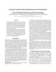
<strong>NXP</strong> Semiconductors<strong>LPC2364</strong>/66/68Fast communication chipThe Thumb set’s 16-bit instruction length allows it to approach twice the density ofstandard ARM code while retaining most of the ARM’s performance advantage over atraditional 16-bit processor using 16-bit registers. This is possible because Thumb codeoperates on the same 32-bit register set as ARM code.Thumb code is able to provide up to 65 % of the code size of ARM, and 160 % of theperformance of an equivalent ARM processor connected to a 16-bit memory system.7.2 On-chip flash programming memoryThe <strong>LPC2364</strong>/66/68 incorporate a 128 kB, 256 kB, and 512 kB flash memory systemrespectively. This memory may be used for both code and data storage. Programming ofthe flash memory may be accomplished in several ways. It may be programmed InSystem via the serial port (UART0). The application program may also erase and/orprogram the flash while the application is running, allowing a great degree of flexibility fordata storage field and firmware upgrades.The flash memory is 128 bits wide and includes pre-fetching and buffering techniques toallow it to operate at SRAM speeds of 72 MHz.The <strong>LPC2364</strong>/66/68 provides a minimum of 100000 write/erase cycles and 20 years ofdata retention.7.3 On-chip SRAMThe <strong>LPC2364</strong>/66/68 includes a SRAM memory of 8 kB, 32 kB, and 32 kB respectively,reserved for the ARM processor exclusive use. This RAM may be used for code and/ordata storage and may be accessed as 8 bits, 16 bits, and 32 bits.A 16 kB SRAM block serving as a buffer for the Ethernet controller and an 8 kB SRAMassociated with the USB device can be used both for data and code storage, too.Remaining SRAM such as a 4 kB USB FIFO and a 2 kB RTC SRAM can be used for datastorage only. The RTC SRAM is battery powered and retains the content in the absence ofthe main power supply.7.4 Memory mapThe <strong>LPC2364</strong>/66/68 memory map incorporates several distinct regions as shown inFigure 3.In addition, the CPU interrupt vectors may be remapped to allow them to reside in eitherflash memory (default), boot ROM, or SRAM (see Section 7.25.6).<strong>LPC2364</strong>_66_68_1© <strong>NXP</strong> B.V. 2006. All rights reserved.Preliminary data sheet Rev. 01 — 31 October 2006 14 of 47
<strong>NXP</strong> Semiconductors<strong>LPC2364</strong>/66/68Fast communication chip4.0 GB3.75 GB3.5 GBAHB PERIPHERALSAPB PERIPHERALS0xFFFF FFFF0xF000 00000xE000 00003.0 GB 0xC000 0000RESERVED ADDRESS SPACE2.0 GB 0x8000 0000BOOT ROM AND BOOT FLASH(BOOT FLASH REMAPPED FROM ON-CHIP FLASH)RESERVED ADDRESS SPACE1.0 GBETHERNET RAM (16 kB)USB RAM (8 KB)RESERVED ADDRESS SPACE32 kB LOCAL ON-CHIP STATIC RAM (<strong>LPC2366</strong>/<strong>LPC2368</strong>)8 kB LOCAL ON-CHIP STATIC RAM (<strong>LPC2364</strong>)0x7FE0 3FFF0x7FE0 00000x7FD0 1FFF0x7FD0 00000x4000 80000x4000 7FFF0x4000 20000x4000 1FFF0x4000 0000RESERVED FOR ON-CHIP MEMORY0.0 GBTOTAL OF 512 kB ON-CHIP NON-VOLATILE MEMORY (<strong>LPC2368</strong>)TOTAL OF 256 kB ON-CHIP NON-VOLATILE MEMORY (<strong>LPC2366</strong>)TOTAL OF 128 kB ON-CHIP NON-VOLATILE MEMORY (<strong>LPC2364</strong>)0x0008 00000x0007 FFFF0x0004 00000x0003 FFFF0x0002 00000x0001 FFFF0x0000 0000002aac577Fig 3.<strong>LPC2364</strong>/66/68 memory map7.5 Interrupt controllerThe ARM processor core has two interrupt inputs called Interrupt Request (IRQ) and FastInterrupt Request (FIQ). The VIC takes 32 interrupt request inputs which can beprogrammed as FIQ or vectored IRQ types. The programmable assignment schememeans that priorities of interrupts from the various peripherals can be dynamicallyassigned and adjusted.<strong>LPC2364</strong>_66_68_1© <strong>NXP</strong> B.V. 2006. All rights reserved.Preliminary data sheet Rev. 01 — 31 October 2006 15 of 47
<strong>NXP</strong> Semiconductors<strong>LPC2364</strong>/66/68Fast communication chipFIQs have the highest priority. If more than one request is assigned to FIQ, the VIC ORsthe requests to produce the FIQ signal to the ARM processor. The fastest possible FIQlatency is achieved when only one request is classified as FIQ, because then the FIQservice routine can simply start dealing with that device. But if more than one request isassigned to the FIQ class, the FIQ service routine can read a word from the VIC thatidentifies which FIQ source(s) is (are) requesting an interrupt.Vectored IRQs, which include all interrupt requests that are not classified as FIQs, have aprogrammable interrupt priority. When more than one interrupt is assigned the samepriority and occur simultaneously, the one connected to the lowest numbered VIC channelwill be serviced first.The VIC ORs the requests from all of the vectored IRQs to produce the IRQ signal to theARM processor. The IRQ service routine can start by reading a register from the VIC andjumping to the address supplied by that register.7.5.1 Interrupt sourcesEach peripheral device has one interrupt line connected to the VIC but may have severalinterrupt flags. Individual interrupt flags may also represent more than one interruptsource.Any pin on PORT0 and PORT2 (total of 42 pins) regardless of the selected function, canbe programmed to generate an interrupt on a rising edge, a falling edge, or both. Suchinterrupt request coming from PORT0 and/or PORT2 will be combined with the EINT3interrupt requests.7.6 Pin connect blockThe pin connect block allows selected pins of the microcontroller to have more than onefunction. Configuration registers control the multiplexers to allow connection between thepin and the on chip peripherals.Peripherals should be connected to the appropriate pins prior to being activated and priorto any related interrupt(s) being enabled. Activity of any enabled peripheral function that isnot mapped to a related pin should be considered undefined.7.7 General purpose DMA controllerThe GPDMA is an AMBA AHB compliant peripheral allowing selected <strong>LPC2364</strong>/66/68peripherals to have DMA support.The GPDMA enables peripheral-to-memory, memory-to-peripheral,peripheral-to-peripheral, and memory-to-memory transactions. Each DMA streamprovides unidirectional serial DMA transfers for a single source and destination. Forexample, a bidirectional port requires one stream for transmit and one for receive. Thesource and destination areas can each be either a memory region or a peripheral, andcan be accessed through the AHB master.7.7.1 Features• Two DMA channels. Each channel can support a unidirectional transfer.• The GPDMA can transfer data between the 8 kB SRAM and peripherals such as theSD/MMC, two SSP, and I 2 S interfaces.<strong>LPC2364</strong>_66_68_1© <strong>NXP</strong> B.V. 2006. All rights reserved.Preliminary data sheet Rev. 01 — 31 October 2006 16 of 47
<strong>NXP</strong> Semiconductors<strong>LPC2364</strong>/66/68Fast communication chip• Single DMA and burst DMA request signals. Each peripheral connected to theGPDMA can assert either a burst DMA request or a single DMA request. The DMAburst size is set by programming the GPDMA.• Memory-to-memory, memory-to-peripheral, peripheral-to-memory, andperipheral-to-peripheral transfers.• Scatter or gather DMA is supported through the use of linked lists. This means thatthe source and destination areas do not have to occupy contiguous areas of memory.• Hardware DMA channel priority. Each DMA channel has a specific hardware priority.DMA channel 0 has the highest priority and channel 1 has the lowest priority. Ifrequests from two channels become active at the same time the channel with thehighest priority is serviced first.• AHB slave DMA programming interface. The GPDMA is programmed by writing to theDMA control registers over the AHB slave interface.• One AHB bus master for transferring data. This interface transfers data when a DMArequest goes active.• 32-bit AHB master bus width.• Incrementing or non-incrementing addressing for source and destination.• Programmable DMA burst size. The DMA burst size can be programmed to moreefficiently transfer data. Usually the burst size is set to half the size of the FIFO in theperipheral.• Internal four-word FIFO per channel.• Supports 8-bit, 16-bit, and 32-bit wide transactions.• An interrupt to the processor can be generated on a DMA completion or when a DMAerror has occurred.• Interrupt masking. The DMA error and DMA terminal count interrupt requests can bemasked.• Raw interrupt status. The DMA error and DMA count raw interrupt status can be readprior to masking.7.8 Fast general purpose parallel I/ODevice pins that are not connected to a specific peripheral function are controlled by theGPIO registers. Pins may be dynamically configured as inputs or outputs. Separateregisters allow setting or clearing any number of outputs simultaneously. The value of theoutput register may be read back as well as the current state of the port pins.<strong>LPC2364</strong>/66/68 use accelerated GPIO functions:• GPIO registers are relocated to the ARM local bus so that the fastest possible I/Otiming can be achieved.• Mask registers allow treating sets of port bits as a group, leaving other bitsunchanged.• All GPIO registers are byte and half-word addressable.• Entire port value can be written in one instruction.<strong>LPC2364</strong>_66_68_1© <strong>NXP</strong> B.V. 2006. All rights reserved.Preliminary data sheet Rev. 01 — 31 October 2006 17 of 47
<strong>NXP</strong> Semiconductors<strong>LPC2364</strong>/66/68Fast communication chipAdditionally, any pin on PORT0 and PORT2 (total of 42 pins) providing a digital functioncan be programmed to generate an interrupt on a rising edge, a falling edge, or both. Theedge detection is asynchronous, so it may operate when clocks are not present such asduring Power-down mode. Each enabled interrupt can be used to wake up the chip fromPower-down mode.7.8.1 Features• Bit level set and clear registers allow a single instruction to set or clear any number ofbits in one port.• Direction control of individual bits.• All I/O default to inputs after reset.• Backward compatibility with other earlier devices is maintained with legacy PORT0and PORT1 registers appearing at the original addresses on the APB bus.7.9 EthernetThe Ethernet block contains a full featured 10 Mbit/s or 100 Mbit/s Ethernet MACdesigned to provide optimized performance through the use of DMA hardwareacceleration. Features include a generous suite of control registers, half or full duplexoperation, flow control, control frames, hardware acceleration for transmit retry, receivepacket filtering and wake-up on LAN activity. Automatic frame transmission and receptionwith scatter-gather DMA off-loads many operations from the CPU.The Ethernet block and the CPU share a dedicated AHB subsystem that is used to accessthe Ethernet SRAM for Ethernet data, control, and status information. All other AHB trafficin the <strong>LPC2364</strong>/66/68 takes place on a different AHB subsystem, effectively separatingEthernet activity from the rest of the system. The Ethernet DMA can also access the USBSRAM if it is not being used by the USB block.The Ethernet block interfaces between an off-chip Ethernet PHY using the Reduced MII(RMII) protocol and the on-chip Media Independent Interface Management (MIIM) serialbus.7.9.1 Features• Ethernet standards support:– Supports 10 Mbit/s or 100 Mbit/s PHY devices including 10 Base-T, 100 Base-TX,100 Base-FX, and 100 Base-T4.– Fully compliant with IEEE standard 802.3.– Fully compliant with 802.3x Full Duplex Flow Control and Half Duplex backpressure.– Flexible transmit and receive frame options.– Virtual Local Area Network (VLAN) frame support.• Memory management:– Independent transmit and receive buffers memory mapped to shared SRAM.– DMA managers with scatter/gather DMA and arrays of frame descriptors.– Memory traffic optimized by buffering and pre-fetching.<strong>LPC2364</strong>_66_68_1© <strong>NXP</strong> B.V. 2006. All rights reserved.Preliminary data sheet Rev. 01 — 31 October 2006 18 of 47
<strong>NXP</strong> Semiconductors<strong>LPC2364</strong>/66/68Fast communication chip• Enhanced Ethernet features:– Receive filtering.– Multicast and broadcast frame support for both transmit and receive.– Optional automatic Frame Check Sequence (FCS) insertion with CircularRedundancy Check (CRC) for transmit.– Selectable automatic transmit frame padding.– Over-length frame support for both transmit and receive allows any length frames.– Promiscuous receive mode.– Automatic collision back-off and frame retransmission.– Includes power management by clock switching.– Wake-on-LAN power management support allows system wake-up: using thereceive filters or a magic frame detection filter.• Physical interface:– Attachment of external PHY chip through standard RMII interface.– PHY register access is available via the MIIM interface.7.10 USB interfaceThe Universal Serial Bus (USB) is a 4-wire bus that supports communication between ahost and a number (127 maximum) of peripherals. The host controller allocates the USBbandwidth to attached devices through a token based protocol. The bus supports hotplugging, unplugging and dynamic configuration of the devices. All transactions areinitiated by the host controller.7.10.1 USB device controllerThe device controller enables 12 Mbit/s data exchange with a USB host controller. Itconsists of register interface, serial interface engine, endpoint buffer memory, and theDMA controller. The serial interface engine decodes the USB data stream and writes datato the appropriate end point buffer memory. The status of a completed USB transfer orerror condition is indicated via status registers. An interrupt is also generated if enabled.The DMA controller when enabled transfers data between the endpoint buffer and theUSB RAM.7.10.2 Features• Fully compliant with USB 2.0 specification (full speed).• Supports 32 physical (16 logical) endpoints with a 4 kB USB buffer.• Supports Control, Bulk, Interrupt and Isochronous endpoints.• Scalable realization of endpoints at run time.• Endpoint Maximum packet size selection (up to USB maximum specification) bysoftware at run time.• Supports SoftConnect and GoodLink features.• While USB is in the Suspend mode, <strong>LPC2364</strong>/66/68 can enter one of the reducedpower down modes and wake up on a USB activity.• Supports DMA transfers with the DMA RAM of 8 kB on all non-control endpoints.<strong>LPC2364</strong>_66_68_1© <strong>NXP</strong> B.V. 2006. All rights reserved.Preliminary data sheet Rev. 01 — 31 October 2006 19 of 47
<strong>NXP</strong> Semiconductors<strong>LPC2364</strong>/66/68Fast communication chip• Allows dynamic switching between CPU-controlled and DMA modes.• Double buffer implementation for Bulk and Isochronous endpoints.7.11 CAN controller and acceptance filtersThe Controller Area Network (CAN) is a serial communications protocol which efficientlysupports distributed real-time control with a very high level of security. Its domain ofapplication ranges from high speed networks to low cost multiplex wiring.The CAN block is intended to support multiple CAN buses simultaneously, allowing thedevice to be used as a gateway, switch, or router among a number of CAN buses inindustrial or automotive applications.Each CAN controller has a register structure similar to the <strong>NXP</strong> SJA1000 and the PeliCANLibrary block, but the 8-bit registers of those devices have been combined in 32-bit wordsto allow simultaneous access in the ARM environment. The main operational difference isthat the recognition of received Identifiers, known in CAN terminology as AcceptanceFiltering, has been removed from the CAN controllers and centralized in a globalAcceptance Filter.7.11.1 Features• Two CAN controllers and buses.• <strong>Data</strong> rates to 1 Mbit/s on each bus.• 32-bit register and RAM access.• Compatible with CAN specification 2.0B, ISO 11898-1.• Global Acceptance Filter recognizes 11-bit and 29-bit receive identifiers for all CANbuses.• Acceptance Filter can provide FullCAN-style automatic reception for selectedStandard Identifiers.• Full CAN messages can generate interrupts.7.12 10-bit ADCThe <strong>LPC2364</strong>/66/68 contain one ADC. It is a single 10-bit successive approximation ADCwith six channels.7.12.1 Features• 10-bit successive approximation ADC.• Input multiplexing among 6 pins.• Power-down mode.• Measurement range 0 V to V i(VREF) .• 10-bit conversion time ≥ 2.44 µs.• Burst conversion mode for single or multiple inputs.• Optional conversion on transition of input pin or Timer Match signal.• Individual result registers for each ADC channel to reduce interrupt overhead.<strong>LPC2364</strong>_66_68_1© <strong>NXP</strong> B.V. 2006. All rights reserved.Preliminary data sheet Rev. 01 — 31 October 2006 20 of 47
<strong>NXP</strong> Semiconductors<strong>LPC2364</strong>/66/68Fast communication chip7.13 10-bit DACThe DAC allows the <strong>LPC2364</strong>/66/68 to generate a variable analog output. The maximumoutput value of the DAC is V i(VREF) .7.13.1 Features7.14 UARTs• 10-bit DAC• Resistor string architecture• Buffered output• Power-down mode• Selectable output driveThe <strong>LPC2364</strong>/66/68 each contain four UARTs. In addition to standard transmit andreceive data lines, UART1 also provides a full modem control handshake interface.The UARTs include a fractional baud rate generator. Standard baud rates such as 115200can be achieved with any crystal frequency above 2 MHz.7.14.1 Features• 16 B Receive and Transmit FIFOs.• Register locations conform to 16C550 industry standard.• Receiver FIFO trigger points at 1 B, 4 B, 8 B, and 14 B.• Built-in fractional baud rate generator covering wide range of baud rates without aneed for external crystals of particular values.• Fractional divider for baud rate control, auto baud capabilities and FIFO controlmechanism that enables software flow control implementation.• UART1 equipped with standard modem interface signals. This module also providesfull support for hardware flow control (auto-CTS/RTS).• UART3 includes an IrDA mode to support infrared communication.7.15 SPI serial I/O controllerThe <strong>LPC2364</strong>/66/68 each contain one SPI controller. SPI is a full duplex serial interfacedesigned to handle multiple masters and slaves connected to a given bus. Only a singlemaster and a single slave can communicate on the interface during a given data transfer.During a data transfer the master always sends 8 bits to 16 bits of data to the slave, andthe slave always sends 8 bits to 16 bits of data to the master.7.15.1 Features• Compliant with SPI specification• Synchronous, serial, full duplex communication• Combined SPI master and slave• Maximum data bit rate of one eighth of the input clock rate• 8 bits to 16 bits per transfer<strong>LPC2364</strong>_66_68_1© <strong>NXP</strong> B.V. 2006. All rights reserved.Preliminary data sheet Rev. 01 — 31 October 2006 21 of 47
<strong>NXP</strong> Semiconductors<strong>LPC2364</strong>/66/68Fast communication chip7.16 SSP serial I/O controllerThe <strong>LPC2364</strong>/66/68 each contain two SSP controllers. The SSP controller is capable ofoperation on a SPI, 4-wire SSI, or Microwire bus. It can interact with multiple masters andslaves on the bus. Only a single master and a single slave can communicate on the busduring a given data transfer. The SSP supports full duplex transfers, with frames of 4 bitsto 16 bits of data flowing from the master to the slave and from the slave to the master. Inpractice, often only one of these data flows carries meaningful data.7.16.1 Features• Compatible with Motorola SPI, 4-wire TI SSI, and National Semiconductor Microwirebuses• Synchronous serial communication• Master or slave operation• 8-frame FIFOs for both transmit and receive• 4-bit to 16-bit frame• DMA transfers supported by GPDMA7.17 SD/MMC card interface (<strong>LPC2368</strong> only)The Secure Digital and Multimedia Card Interface (MCI) allows access to external SDmemory cards. The SD card interface conforms to the SD Multimedia Card SpecificationVersion 2.11.7.17.1 Features• The MCI interface provides all functions specific to the SD/MMC memory card. Theseinclude the clock generation unit, power management control, and command and datatransfer.• Conforms to Multimedia Card Specification v2.11.• Conforms to Secure Digital Memory Card Physical Layer Specification, v0.96.• Can be used as a multimedia card bus or a secure digital memory card bus host. TheSD/MMC can be connected to several multimedia cards or a single secure digitalmemory card.• DMA supported through the GPDMA controller.7.18 I 2 C-bus serial I/O controllersThe <strong>LPC2364</strong>/66/68 each contain three I 2 C-bus controllers.The I 2 C-bus is bidirectional, for inter-IC control using only two wires: a serial clock line(SCL), and a serial data line (SDA). Each device is recognized by a unique address andcan operate as either a receiver-only device (e.g., an LCD driver) or a transmitter with thecapability to both receive and send information (such as memory). Transmitters and/orreceivers can operate in either master or slave mode, depending on whether the chip hasto initiate a data transfer or is only addressed. The I 2 C is a multi-master bus, it can becontrolled by more than one bus master connected to it.The I 2 C-bus implemented in <strong>LPC2364</strong>/66/68 supports bit rates up to 400 kbit/s (FastI 2 C-bus).<strong>LPC2364</strong>_66_68_1© <strong>NXP</strong> B.V. 2006. All rights reserved.Preliminary data sheet Rev. 01 — 31 October 2006 22 of 47
<strong>NXP</strong> Semiconductors<strong>LPC2364</strong>/66/68Fast communication chip7.18.1 Features• I 2 C0 is a standard I 2 C compliant bus interface with open-drain pins.• I 2 C1 and I 2 C2 use standard I/O pins and do not support powering off of individualdevices connected to the same bus lines.• Easy to configure as master, slave, or master/slave.• Programmable clocks allow versatile rate control.• Bidirectional data transfer between masters and slaves.• Multi-master bus (no central master).• Arbitration between simultaneously transmitting masters without corruption of serialdata on the bus.• Serial clock synchronization allows devices with different bit rates to communicate viaone serial bus.• Serial clock synchronization can be used as a handshake mechanism to suspend andresume serial transfer.• The I 2 C-bus can be used for test and diagnostic purposes.7.19 I 2 S-bus serial I/O controllersThe I 2 S-bus provides a standard communication interface for digital audio applications.The I 2 S-bus specification defines a 3-wire serial bus using one data line, one clock line,and one word select signal. The basic I 2 S connection has one master, which is always themaster, and one slave. The I 2 S interface on the <strong>LPC2364</strong>/66/68 provides a separatetransmit and receive channel, each of which can operate as either a master or a slave.7.19.1 Features• The interface has separate input/output channels each of which can operate in masteror slave mode.• Capable of handling 8-bit, 16-bit, and 32-bit word sizes.• Mono and stereo audio data supported.• The sampling frequency can range from 16 kHz to 48 kHz (16, 22.05, 32, 44.1,48) kHz.• Configurable word select period in master mode (separately for I 2 S input and output).• Two 8-word FIFO data buffers are provided, one for transmit and one for receive.• Generates interrupt requests when buffer levels cross a programmable boundary.• Two DMA requests, controlled by programmable buffer levels. These are connectedto the GPDMA block.• Controls include reset, stop and mute options separately for I 2 S input and I 2 S output.<strong>LPC2364</strong>_66_68_1© <strong>NXP</strong> B.V. 2006. All rights reserved.Preliminary data sheet Rev. 01 — 31 October 2006 23 of 47
<strong>NXP</strong> Semiconductors<strong>LPC2364</strong>/66/68Fast communication chip7.20 General purpose 32-bit timers/external event countersThe <strong>LPC2364</strong>/66/68 include four 32-bit Timer/Counters. The Timer/Counter is designed tocount cycles of the system derived clock or an externally-supplied clock. It can optionallygenerate interrupts or perform other actions at specified timer values, based on fourmatch registers. The Timer/Counter also includes two capture inputs to trap the timervalue when an input signal transitions, optionally generating an interrupt.7.20.1 Features• A 32-bit Timer/Counter with a programmable 32-bit prescaler.• Counter or Timer operation.• Two 32-bit capture channels per timer, that can take a snapshot of the timer valuewhen an input signal transitions. A capture event may also generate an interrupt.• Four 32-bit match registers that allow:– Continuous operation with optional interrupt generation on match.– Stop timer on match with optional interrupt generation.– Reset timer on match with optional interrupt generation.• Up to four external outputs corresponding to match registers, with the followingcapabilities:– Set LOW on match.– Set HIGH on match.– Toggle on match.– Do nothing on match.7.21 Pulse width modulatorThe PWM is based on the standard Timer block and inherits all of its features, althoughonly the PWM function is pinned out on the <strong>LPC2364</strong>/66/68. The Timer is designed tocount cycles of the system derived clock and optionally switch pins, generate interrupts orperform other actions when specified timer values occur, based on seven match registers.The PWM function is in addition to these features, and is based on match register events.The ability to separately control rising and falling edge locations allows the PWM to beused for more applications. For instance, multi-phase motor control typically requiresthree non-overlapping PWM outputs with individual control of all three pulse widths andpositions.Two match registers can be used to provide a single edge controlled PWM output. Onematch register (PWMMR0) controls the PWM cycle rate, by resetting the count uponmatch. The other match register controls the PWM edge position. Additional single edgecontrolled PWM outputs require only one match register each, since the repetition rate isthe same for all PWM outputs. Multiple single edge controlled PWM outputs will all have arising edge at the beginning of each PWM cycle, when an PWMMR0 match occurs.Three match registers can be used to provide a PWM output with both edges controlled.Again, the PWMMR0 match register controls the PWM cycle rate. The other matchregisters control the two PWM edge positions. Additional double edge controlled PWMoutputs require only two match registers each, since the repetition rate is the same for allPWM outputs.<strong>LPC2364</strong>_66_68_1© <strong>NXP</strong> B.V. 2006. All rights reserved.Preliminary data sheet Rev. 01 — 31 October 2006 24 of 47
<strong>NXP</strong> Semiconductors<strong>LPC2364</strong>/66/68Fast communication chipWith double edge controlled PWM outputs, specific match registers control the rising andfalling edge of the output. This allows both positive going PWM pulses (when the risingedge occurs prior to the falling edge), and negative going PWM pulses (when the fallingedge occurs prior to the rising edge).7.21.1 Features• <strong>LPC2364</strong>/66/68 has one PWM block with Counter or Timer operation (may use theperipheral clock or one of the capture inputs as the clock source).• Seven match registers allow up to 6 single edge controlled or 3 double edgecontrolled PWM outputs, or a mix of both types. The match registers also allow:– Continuous operation with optional interrupt generation on match.– Stop timer on match with optional interrupt generation.– Reset timer on match with optional interrupt generation.• Supports single edge controlled and/or double edge controlled PWM outputs. Singleedge controlled PWM outputs all go high at the beginning of each cycle unless theoutput is a constant low. Double edge controlled PWM outputs can have either edgeoccur at any position within a cycle. This allows for both positive going and negativegoing pulses.• Pulse period and width can be any number of timer counts. This allows completeflexibility in the trade-off between resolution and repetition rate. All PWM outputs willoccur at the same repetition rate.• Double edge controlled PWM outputs can be programmed to be either positive goingor negative going pulses.• Match register updates are synchronized with pulse outputs to prevent generation oferroneous pulses. Software must ‘release’ new match values before they can becomeeffective.• May be used as a standard timer if the PWM mode is not enabled.• A 32-bit Timer/Counter with a programmable 32-bit Prescaler.7.22 Watchdog timerThe purpose of the watchdog is to reset the microcontroller within a reasonable amount oftime if it enters an erroneous state. When enabled, the watchdog will generate a systemreset if the user program fails to ‘feed’ (or reload) the watchdog within a predeterminedamount of time.7.22.1 Features• Internally resets chip if not periodically reloaded.• Debug mode.• Enabled by software but requires a hardware reset or a watchdog reset/interrupt to bedisabled.• Incorrect/Incomplete feed sequence causes reset/interrupt if enabled.• Flag to indicate watchdog reset.• Programmable 32-bit timer with internal prescaler.<strong>LPC2364</strong>_66_68_1© <strong>NXP</strong> B.V. 2006. All rights reserved.Preliminary data sheet Rev. 01 — 31 October 2006 25 of 47
<strong>NXP</strong> Semiconductors<strong>LPC2364</strong>/66/68Fast communication chip• Selectable time period from (T cy(WDCLK) × 256 × 4) to (T cy(WDCLK) × 2 32 × 4) inmultiples of T cy(WDCLK) × 4.• The Watchdog Clock (WDCLK) source can be selected from the RTC clock, theInternal RC oscillator (IRC), or the APB peripheral clock. This gives a wide range ofpotential timing choices of Watchdog operation under different power reductionconditions. It also provides the ability to run the WDT from an entirely internal sourcethat is not dependent on an external crystal and its associated components andwiring, for increased reliability.7.23 RTC and battery RAMThe RTC is a set of counters for measuring time when system power is on, and optionallywhen it is off. It uses little power in Power-down mode. On the <strong>LPC2364</strong>/66/68, the RTCcan be clocked by a separate 32.768 kHz oscillator, or by a programmable prescaledivider based on the APB clock. Also, the RTC is powered by its own power supply pin,VBAT, which can be connected to a battery or to the same 3.3 V supply used by the rest ofthe device.The VBAT pin supplies power only to the RTC and the Battery RAM. These two functionsrequire a minimum of power to operate, which can be supplied by an external battery.7.23.1 Features• Measures the passage of time to maintain a calendar and clock.• Ultra low power design to support battery powered systems.• Provides Seconds, Minutes, Hours, Day of Month, Month, Year, Day of Week, andDay of Year.• Dedicated 32 kHz oscillator or programmable prescaler from APB clock.• Dedicated power supply pin can be connected to a battery or to the main 3.3 V.• Periodic interrupts can be generated from increments of any field of the time registers,and selected fractional second values.• 2 kB data SRAM powered by VBAT.• RTC and Battery RAM power supply is isolated from the rest of the chip.7.24 Clocking and power control7.24.1 Crystal oscillatorsThe <strong>LPC2364</strong>/66/68 includes three independent oscillators. These are the Main Oscillator,the Internal RC oscillator, and the RTC oscillator. Each oscillator can be used for morethan one purpose as required in a particular application. Any of the three clock sourcescan be chosen by software to drive the PLL and ultimately the CPU.Following reset, the <strong>LPC2364</strong>/66/68 will operate from the Internal RC oscillator untilswitched by software. This allows systems to operate without any external crystal and thebootloader code to operate at a known frequency.<strong>LPC2364</strong>_66_68_1© <strong>NXP</strong> B.V. 2006. All rights reserved.Preliminary data sheet Rev. 01 — 31 October 2006 26 of 47
<strong>NXP</strong> Semiconductors<strong>LPC2364</strong>/66/68Fast communication chip7.24.1.1 Internal RC oscillatorThe IRC may be used as the clock source for the WDT, and/or as the clock that drives thePLL and subsequently the CPU. The nominal IRC frequency is 4 MHz. The IRC istrimmed to 1 % accuracy.Upon power-up or any chip reset, the <strong>LPC2364</strong>/66/68 uses the IRC as the clock source.Software may later switch to one of the other available clock sources.7.24.1.2 Main oscillatorThe main oscillator can be used as the clock source for the CPU, with or without using thePLL. The main oscillator operates at frequencies of 1 MHz to 24 MHz. This frequency canbe boosted to a higher frequency, up to the maximum CPU operating frequency, by thePLL. The clock selected as the PLL input is PLLCLKIN. The ARM processor clockfrequency is referred to as CCLK elsewhere in this document. The frequencies ofPLLCLKIN and CCLK are the same value unless the PLL is active and connected. Theclock frequency for each peripheral can be selected individually and is referred to asPCLK. Refer to Section 7.24.2 for additional information.7.24.1.3 RTC oscillatorThe RTC oscillator can be used as the clock source for the RTC and/or the WDT. Also, theRTC oscillator can be used to drive the PLL and the CPU.7.24.2 PLLThe PLL accepts an input clock frequency in the range of 32 kHz to 50 MHz. The inputfrequency is multiplied up to a high frequency, then divided down to provide the actualclock used by the CPU and the USB block.The PLL input, in the range of 32 kHZ to 50 MHz, may initially be divided down by a value‘N’, which may be in the range of 1 to 256. This input division provides a wide range ofoutput frequencies from the same input frequency.Following the PLL input divider is the PLL multiplier. This can multiply the input divideroutput through the use of a Current Controlled Oscillator (CCO) by a value ‘M’, in therange of 1 through 32768. The resulting frequency must be in the range of 275 MHz to550 MHz. The multiplier works by dividing the CCO output by the value of M, then using aphase-frequency detector to compare the divided CCO output to the multiplier input. Theerror value is used to adjust the CCO frequency.The PLL is turned off and bypassed following a chip Reset and by entering Power-downmode. PLL is enabled by software only. The program must configure and activate the PLL,wait for the PLL to Lock, then connect to the PLL as a clock source.7.24.3 Wake-up timerThe <strong>LPC2364</strong>/66/68 begins operation at power-up and when awakened from Power-downmode or Deep power-down mode by using the 4 MHz IRC oscillator as the clock source.This allows chip operation to resume quickly. If the main oscillator or the PLL is needed bythe application, software will need to enable these features and wait for them to stabilizebefore they are used as a clock source.<strong>LPC2364</strong>_66_68_1© <strong>NXP</strong> B.V. 2006. All rights reserved.Preliminary data sheet Rev. 01 — 31 October 2006 27 of 47
<strong>NXP</strong> Semiconductors<strong>LPC2364</strong>/66/68Fast communication chipWhen the main oscillator is initially activated, the wake-up timer allows software to ensurethat the main oscillator is fully functional before the processor uses it as a clock sourceand starts to execute instructions. This is important at power on, all types of Reset, andwhenever any of the aforementioned functions are turned off for any reason. Since theoscillator and other functions are turned off during Power-down mode, any wake-up of theprocessor from Power-down mode makes use of the wake-up Timer.The Wake-up Timer monitors the crystal oscillator to check whether it is safe to begincode execution. When power is applied to the chip, or when some event caused the chipto exit Power-down mode, some time is required for the oscillator to produce a signal ofsufficient amplitude to drive the clock logic. The amount of time depends on many factors,including the rate of V DD(3V3) ramp (in the case of power on), the type of crystal and itselectrical characteristics (if a quartz crystal is used), as well as any other external circuitry(e.g., capacitors), and the characteristics of the oscillator itself under the existing ambientconditions.7.24.4 Power controlThe <strong>LPC2364</strong>/66/68 supports a variety of power control features. There are four specialmodes of processor power reduction: Idle mode, Sleep mode, Power-down mode, andDeep power-down mode. The CPU clock rate may also be controlled as needed bychanging clock sources, reconfiguring PLL values, and/or altering the CPU clock dividervalue. This allows a trade-off of power versus processing speed based on applicationrequirements. In addition, Peripheral Power Control allows shutting down the clocks toindividual on-chip peripherals, allowing fine tuning of power consumption by eliminating alldynamic power use in any peripherals that are not required for the application. Each of theperipherals has its own clock divider which provides even better power control.The <strong>LPC2364</strong>/66/68 also implements a separate power domain in order to allow turningoff power to the bulk of the device while maintaining operation of the RTC and a smallSRAM, referred to as the Battery RAM.7.24.4.1 Idle modeIn Idle mode, execution of instructions is suspended until either a Reset or interruptoccurs. Peripheral functions continue operation during Idle mode and may generateinterrupts to cause the processor to resume execution. Idle mode eliminates dynamicpower used by the processor itself, memory systems and related controllers, and internalbuses.7.24.4.2 Sleep modeIn Sleep mode, the oscillator is shut down and the chip receives no internal clocks. Theprocessor state and registers, peripheral registers, and internal SRAM values arepreserved throughout Sleep mode and the logic levels of chip pins remain static. Theoutput of the IRC is disabled but the IRC is not powered down for a fast wake-up later. The32 kHz RTC oscillator is not stopped because the RTC interrupts may be used as thewake-up source. The PLL is automatically turned off and disconnected. The CCLK andUSB clock dividers automatically get reset to zero.The Sleep mode can be terminated and normal operation resumed by either a Reset orcertain specific interrupts that are able to function without clocks. Since all dynamicoperation of the chip is suspended, Sleep mode reduces chip power consumption to avery low value. The flash memory is left on in Sleep mode, allowing a very quick wake-up.<strong>LPC2364</strong>_66_68_1© <strong>NXP</strong> B.V. 2006. All rights reserved.Preliminary data sheet Rev. 01 — 31 October 2006 28 of 47
<strong>NXP</strong> Semiconductors<strong>LPC2364</strong>/66/68Fast communication chipOn the wake-up of sleep mode, if the IRC was used before entering sleep mode, the codeexecution and peripherals activities will resume after 4 cycles expire. If the main externaloscillator was used, the code execution will resume when 4096 cycles expire.The customers need to reconfigure the PLL and clock dividers accordingly.7.24.4.3 Power-down modePower-down mode does everything that Sleep mode does, but also turns off the IRCoscillator and the flash memory. This saves more power, but requires waiting forresumption of flash operation before execution of code or data access in the flash memorycan be accomplished.On the wake-up of power-down mode, if the IRC was used before entering power-downmode, it will take IRC 60 µs to start-up. After this 4 IRC cycles will expire before the codeexecution can then be resumed if the code was running from SRAM. In the meantime, theflash wake-up timer then counts 4 MHz IRC clock cycles to make the 100 µs flash start-uptime. When it times out, access to the flash will be allowed. The customers need toreconfigure the PLL and clock dividers accordingly.7.24.4.4 Deep power-down modeDeep power-down mode is like Power-down mode, but the on-chip regulator that suppliespower to internal logic is also shut off. This produces the lowest possible powerconsumption without actually removing power from the entire chip. Since Deeppower-down mode shuts down the on-chip logic power supply, there is no register ormemory retention, and resumption of operation involves the same activities as a full-chipreset.If power is supplied to the <strong>LPC2364</strong>/66/68 during Deep power-down mode, wake-up canbe caused by external Reset.While in Deep power-down mode, external device power may be removed. In this case,the <strong>LPC2364</strong>/66/68 will start up when external power is restored.Essential data may be retained through Deep power-down mode (or through completepowering off of the chip) by storing data in the Battery RAM, as long as the external powerto the VBAT pin is maintained.7.24.4.5 Power domainsThe <strong>LPC2364</strong>/66/68 provides two independent power domains that allow the bulk of thedevice to have power removed while maintaining operation of the RTC and the BatteryRAM.The 3.3 V (V DD(3V3) ) pins power both the on-chip DC-to-DC converter and the I/O pads.These pins provide the power for the CPU and most of the peripherals. If power isremoved from the V DD(3V3) pins, the CPU and related peripherals stop.The VBAT pin supplies power only to the RTC and the Battery RAM. These two functionsrequire a minimum of power to operate, which can be supplied by an external battery.<strong>LPC2364</strong>_66_68_1© <strong>NXP</strong> B.V. 2006. All rights reserved.Preliminary data sheet Rev. 01 — 31 October 2006 29 of 47
<strong>NXP</strong> Semiconductors<strong>LPC2364</strong>/66/68Fast communication chip7.25 System control7.25.1 ResetReset has four sources on the <strong>LPC2364</strong>/66/68: the RESET pin, the Watchdog reset,power-on reset, and the BrownOut Detection (BOD) circuit. The RESET pin is a Schmitttrigger input pin. Assertion of chip Reset by any source, once the operating voltage attainsa usable level, starts the Wake-up timer (see description in Section 7.24.3 “Wake-uptimer”), causing reset to remain asserted until the external Reset is de-asserted, theoscillator is running, a fixed number of clocks have passed, and the flash controller hascompleted its initialization.When the internal Reset is removed, the processor begins executing at address 0, whichis initially the Reset vector mapped from the Boot Block. At that point, all of the processorand peripheral registers have been initialized to predetermined values.7.25.2 Brownout detectionThe <strong>LPC2364</strong>/66/68 includes 2-stage monitoring of the voltage on the V DD(3V3) pins. If thisvoltage falls below 2.95 V, the BOD asserts an interrupt signal to the Vectored InterruptController. This signal can be enabled for interrupt in the Interrupt Enable Register in theVIC in order to cause a CPU interrupt; if not, software can monitor the signal by reading adedicated status register.The second stage of low-voltage detection asserts Reset to inactivate the <strong>LPC2364</strong>/66/68when the voltage on the V DD(3V3) pins falls below 2.65 V. This Reset prevents alteration ofthe flash as operation of the various elements of the chip would otherwise becomeunreliable due to low voltage. The BOD circuit maintains this reset down below 1 V, atwhich point the power-on reset circuitry maintains the overall Reset.Both the 2.95 V and 2.65 V thresholds include some hysteresis. In normal operation, thishysteresis allows the 2.95 V detection to reliably interrupt, or a regularly-executed eventloop to sense the condition.7.25.3 Code securityThis feature of the <strong>LPC2364</strong>/66/68 allows an application to control whether it can bedebugged or protected from observation.If after reset the on-chip bootloader detects a valid checksum in flash and reads0x8765 4321 from address 0x1FC in flash, debugging will be disabled and thus the codein flash will be protected from observation. Once debugging is disabled, it can be enabledby performing a full chip erase using the ISP.7.25.4 AHB busThe <strong>LPC2364</strong>/66/68 implements two AHB buses in order to allow the Ethernet block tooperate without interference caused by other system activity. The primary AHB, referredto as AHB1, includes the Vectored Interrupt Controller, GPDMA controller, USB interface,and 8 kB SRAM primarily intended for use by the USB.The second AHB, referred to as AHB2, includes only the Ethernet block and anassociated 16 kB SRAM. In addition, a bus bridge is provided that allows the secondaryAHB to be a bus master on AHB1, allowing expansion of Ethernet buffer space intounused space in memory residing on AHB1.<strong>LPC2364</strong>_66_68_1© <strong>NXP</strong> B.V. 2006. All rights reserved.Preliminary data sheet Rev. 01 — 31 October 2006 30 of 47
<strong>NXP</strong> Semiconductors<strong>LPC2364</strong>/66/68Fast communication chipIn summary, bus masters with access to AHB1 are the ARM7 itself, the USB block, theGPDMA function, and the Ethernet block (via the bus bridge from AHB2). Bus masterswith access to AHB2 are the ARM7 and the Ethernet block.7.25.5 External interrupt inputsThe <strong>LPC2364</strong>/66/68 include up to 46 edge sensitive interrupt inputs combined with up toto four level sensitive external interrupt inputs as selectable pin functions. The externalinterrupt inputs can optionally be used to wake up the processor from Power-down mode.7.25.6 Memory mapping controlThe memory mapping control alters the mapping of the interrupt vectors that appear at thebeginning at address 0x0000 0000. Vectors may be mapped to the bottom of the BootROM or the SRAM. This allows code running in different memory spaces to have controlof the interrupts.7.26 Emulation and debuggingThe <strong>LPC2364</strong>/66/68 support emulation and debugging via a JTAG serial port. A trace portallows tracing program execution. Debugging and trace functions are multiplexed onlywith GPIOs on P2[0] to P2[9]. This means that all communication, timer, and interfaceperipherals residing on other pins are available during the development and debuggingphase as they are when the application is run in the embedded system itself.7.26.1 EmbeddedICEThe EmbeddedICE logic provides on-chip debug support. The debugging of the targetsystem requires a host computer running the debugger software and an EmbeddedICEprotocol convertor. The EmbeddedICE protocol convertor converts the Remote DebugProtocol commands to the JTAG data needed to access the ARM7TDMI-S core presenton the target system.The ARM core has a Debug Communication Channel (DCC) function built-in. The DCCallows a program running on the target to communicate with the host debugger or anotherseparate host without stopping the program flow or even entering the debug state. TheDCC is accessed as a coprocessor 14 by the program running on the ARM7TDMI-S core.The DCC allows the JTAG port to be used for sending and receiving data without affectingthe normal program flow. The DCC data and control registers are mapped in to addressesin the EmbeddedICE logic.7.26.2 Embedded traceSince the <strong>LPC2364</strong>/66/68 have significant amounts of on-chip memories, it is not possibleto determine how the processor core is operating simply by observing the external pins.The ETM provides real-time trace capability for deeply embedded processor cores. Itoutputs information about processor execution to a trace port. A software debugger allowsconfiguration of the ETM using a JTAG interface and displays the trace information thathas been captured.The ETM is connected directly to the ARM core and not to the main AMBA system bus. Itcompresses the trace information and exports it through a narrow trace port. An externalTrace Port Analyzer captures the trace information under software debugger control. Thetrace port can broadcast the Instruction trace information. Instruction trace (or PC trace)shows the flow of execution of the processor and provides a list of all the instructions that<strong>LPC2364</strong>_66_68_1© <strong>NXP</strong> B.V. 2006. All rights reserved.Preliminary data sheet Rev. 01 — 31 October 2006 31 of 47
<strong>NXP</strong> Semiconductors<strong>LPC2364</strong>/66/68Fast communication chipwere executed. Instruction trace is significantly compressed by only broadcasting branchaddresses as well as a set of status signals that indicate the pipeline status on a cycle bycycle basis. Trace information generation can be controlled by selecting the triggerresource. Trigger resources include address comparators, counters and sequencers.Since trace information is compressed the software debugger requires a static image ofthe code being executed. Self-modifying code can not be traced because of thisrestriction.7.26.3 RealMonitorRealMonitor is a configurable software module, developed by ARM Inc., which enablesreal-time debug. It is a lightweight debug monitor that runs in the background while usersdebug their foreground application. It communicates with the host using the DCC, which ispresent in the EmbeddedICE logic. The <strong>LPC2364</strong>/66/68 contain a specific configuration ofRealMonitor software programmed into the on-chip ROM memory.<strong>LPC2364</strong>_66_68_1© <strong>NXP</strong> B.V. 2006. All rights reserved.Preliminary data sheet Rev. 01 — 31 October 2006 32 of 47
<strong>NXP</strong> Semiconductors<strong>LPC2364</strong>/66/68Fast communication chip8. Limiting valuesTable 4. Limiting valuesIn accordance with the Absolute Maximum Rating System (IEC 60134). [1]Symbol Parameter Conditions Min Max UnitV DD(3V3) supply voltage (3.3 V) core and external 3.0 3.6 VrailV DD(DCDC)(3V3) DC-to-DC converter supply voltage3.0 3.6 V(3.3 V)V DDA analog 3.3 V pad supply voltage −0.5 +4.6 VV i(VBAT) input voltage on pin VBAT for the RTC −0.5 +4.6 VV i(VREF) input voltage on pin VREF −0.5 +4.6 VV IA analog input voltage on ADC related−0.5 +5.1 VpinsV I input voltage 5 V tolerant I/Opins; only validwhen the V DD(3V3)supply voltage ispresent[2]−0.5 +6.0 Vother I/O pins[2][3]−0.5 V DD(3V3) + V0.5I DD supply current per supply pin[4]- 100 mAI SS ground current per ground pin[4]- 100 mAT stg storage temperature[5]−40 +125 °CP tot(pack) total power dissipation (per package) based on packageheat transfer, notdevice powerconsumption- 1.5 WV esd electrostatic discharge voltage human bodymodel; all pins[6]−2000 +2000 V[1] The following applies to the Limiting values:a) This product includes circuitry specifically designed for the protection of its internal devices from the damaging effects of excessivestatic charge. Nonetheless, it is suggested that conventional precautions be taken to avoid applying greater than the ratedmaximum.b) Parameters are valid over operating temperature range unless otherwise specified. All voltages are with respect to V SS unlessotherwise noted.[2] Including voltage on outputs in 3-state mode.[3] Not to exceed 4.6 V.[4] The peak current is limited to 25 times the corresponding maximum current.[5] Dependent on package type.[6] Human body model: equivalent to discharging a 100 pF capacitor through a 1.5 kΩ series resistor.<strong>LPC2364</strong>_66_68_1© <strong>NXP</strong> B.V. 2006. All rights reserved.Preliminary data sheet Rev. 01 — 31 October 2006 33 of 47
<strong>NXP</strong> Semiconductors<strong>LPC2364</strong>/66/68Fast communication chip9. Static characteristicsTable 5. Static characteristicsT amb = −40 °C to +85 °C for commercial applications, unless otherwise specified.Symbol Parameter Conditions Min Typ [1] Max UnitV DD(3V3) supply voltage (3.3 V) core and external rail 3.0 3.3 3.6 VV DD(DCDC)(3V3) DC-to-DC converter3.0 3.3 3.6 Vsupply voltage (3.3 V)V DDAanalog 3.3 V pad supply3.0 3.3 3.6 VvoltageV i(VBAT) input voltage on pin[2]2.0 3.3 3.6 VVBATV i(VREF) input voltage on pin2.5 3.3 V DDA VVREFStandard port pins, RESET, RTCKI IL LOW-level input current V I = 0 V; no pull-up - - 3 µAI IHI OZHIGH-level inputcurrentOFF-state outputcurrentV I =V DD(3V3) ; nopull-downV O =0V; V O =V DD(3V3) ;no pull-up/downI latch I/O latch-up current −(0.5V DD(3V3) ) < V I
<strong>NXP</strong> Semiconductors<strong>LPC2364</strong>/66/68Fast communication chipTable 5. Static characteristics …continuedT amb = −40 °C to +85 °C for commercial applications, unless otherwise specified.Symbol Parameter Conditions Min Typ [1] Max UnitI DD(DCDC)act(3V3)I DD(DCDC)pd(3V3)I DD(DCDC)dpd(3V3)active mode DC-to-DCconverter supplycurrent (3.3 V)power-down modeDC-to-DC convertersupply current (3.3 V)deep power-downmode DC-to-DCconverter supplycurrent (3.3 V)active mode batterysupply currentV DD(DCDC)(3V3) =3.3V;T amb =25°C; codewhile(1){}-executed from flash; noperipherals enabled;PCLK = CCLK:CCLK = 10 MHz15 mACCLK = 72 MHz - 63 mAall peripherals enabled;-PCLK = CCLK / 8:CCLK = 10 MHz21 mACCLK = 72 MHz - 92 mAall peripherals enabled;-PCLK = CCLK:CCLK = 10 MHz27 mACCLK = 72 MHz - 125 mAV DD(DCDC)(3V3) =3.3V;T amb =25°CV DD(DCDC)(3V3) =3.3V;T amb =25°C150 µA15 µAI BATactDC-to-DC converter on[9]20 µADC-to-DC converter off[9]28 µAI 2 C-bus pins (P0[27] and P0[28])V IHHIGH-level input0.7V DD(3V3) - - VvoltageV IL LOW-level input voltage - - 0.3V DD(3V3) VV hys hysteresis voltage - 0.5V DD(3V3) - VV OLLOW-level output I OLS =3 mA[6]- - 0.4 VvoltageI LI input leakage current V I =V DD(3V3)[10]- 2 4 µAV I =5V - 10 22 µAOscillator pinsV i(XTAL1) input voltage on pin0 - 1.8 VXTAL1V o(XTAL2) output voltage on pin0 - 1.8 VXTAL2V i(RTCX1) input voltage on pin0 - 1.8 VRTCX1V o(RTCX2) output voltage on pinRTCX20 - 1.8 V<strong>LPC2364</strong>_66_68_1© <strong>NXP</strong> B.V. 2006. All rights reserved.Preliminary data sheet Rev. 01 — 31 October 2006 35 of 47
<strong>NXP</strong> Semiconductors<strong>LPC2364</strong>/66/68Fast communication chipTable 5. Static characteristics …continuedT amb = −40 °C to +85 °C for commercial applications, unless otherwise specified.Symbol Parameter Conditions Min Typ [1] Max UnitUSB pinsI OZOFF-state output 0V
<strong>NXP</strong> Semiconductors<strong>LPC2364</strong>/66/68Fast communication chipTable 6. ADC static characteristics …continuedV DDA = 2.5 V to 3.6 V; T amb = −40 °C to +85 °C unless otherwise specified; ADC frequency 4.5 MHz.Symbol Parameter Conditions Min Typ Max UnitE G gain error[1][6]- - ±0.5 %E T absolute error[1][7]- - ±4 LSBR vsi voltage source interfaceresistance[8]- - 40 kΩ[1] Conditions: V SSA =0V, V DDA =3.3V.[2] The ADC is monotonic, there are no missing codes.[3] The differential linearity error (E D ) is the difference between the actual step width and the ideal step width. See Figure 4.[4] The integral non-linearity (E L(adj) ) is the peak difference between the center of the steps of the actual and the ideal transfer curve afterappropriate adjustment of gain and offset errors. See Figure 4.[5] The offset error (E O ) is the absolute difference between the straight line which fits the actual curve and the straight line which fits theideal curve. See Figure 4.[6] The gain error (E G ) is the relative difference in percent between the straight line fitting the actual transfer curve after removing offseterror, and the straight line which fits the ideal transfer curve. See Figure 4.[7] The absolute error (E T ) is the maximum difference between the center of the steps of the actual transfer curve of the non-calibratedADC and the ideal transfer curve. See Figure 4.[8] See Figure 5.<strong>LPC2364</strong>_66_68_1© <strong>NXP</strong> B.V. 2006. All rights reserved.Preliminary data sheet Rev. 01 — 31 October 2006 37 of 47
<strong>NXP</strong> Semiconductors<strong>LPC2364</strong>/66/68Fast communication chipoffseterrorE OgainerrorE G102310221021102010191018(2)codeout76(1)54(5)3(4)2(3)11 LSB(ideal)01 2 3 4 5 6offset errorE OV IA (LSB ideal )71018 1019 1020 1021 1022 1023V DDA − V SSA1 LSB =10241024002aac046(1) Example of an actual transfer curve.(2) The ideal transfer curve.(3) Differential linearity error (E D ).(4) Integral non-linearity (E L(adj) ).(5) Center of a step of the actual transfer curve.Fig 4. ADC characteristics<strong>LPC2364</strong>_66_68_1© <strong>NXP</strong> B.V. 2006. All rights reserved.Preliminary data sheet Rev. 01 — 31 October 2006 38 of 47
<strong>NXP</strong> Semiconductors<strong>LPC2364</strong>/66/68Fast communication chip<strong>LPC2364</strong>/66/68ADx[y] SAMPLE20 kΩADx[y]Rvsi3 pF 5 pFVEXTV SS002aac575Fig 5.Suggested ADC interface - <strong>LPC2364</strong>/66/68 AD0[y] pin<strong>LPC2364</strong>_66_68_1© <strong>NXP</strong> B.V. 2006. All rights reserved.Preliminary data sheet Rev. 01 — 31 October 2006 39 of 47
<strong>NXP</strong> Semiconductors<strong>LPC2364</strong>/66/68Fast communication chip10. Dynamic characteristicsTable 7. Dynamic characteristics of USB pins (full-speed)C L = 50 pF; R pu = 1.5 kΩ on D+ to V DD(3V3) , unless otherwise specified.Symbol Parameter Conditions Min Typ Max Unitt r rise time 10 % to 90 % 8.5 - 13.8 nst f fall time 10 % to 90 % 7.7 - 13.7 nst FRFMdifferential rise and fall timet r /t f - - 109 %matchingV CRS output signal crossover voltage 1.3 - 2.0 Vt FEOPT source SE0 interval of EOP see Figure 7 160 - 175 nst FDEOPsource jitter for differential transition see Figure 7 −2 - +5 nsto SE0 transitiont JR1 receiver jitter to next transition −18.5 - +18.5 nst JR2 receiver jitter for paired transitions 10 % to 90 % −9 - +9 nst EOPR1 EOP width at receiver must reject as[1]40 - - nsEOP; seeFigure 7t EOPR2 EOP width at receiver must accept asEOP; seeFigure 7[1]82 - - ns[1] Characterized but not implemented as production test. Guaranteed by design.Table 8. Dynamic characteristicsT amb = −40 °C to +85 °C for commercial applications; V DD(3V3) over specified ranges. [1]Symbol Parameter Conditions Min Typ [2] Max UnitExternal clockf osc oscillator frequency 10 - 25 MHzT cy(clk) clock cycle time 40 - 100 nst CHCX clock HIGH time T cy(clk) × 0.4 - - nst CLCX clock LOW time T cy(clk) × 0.4 - - nst CLCH clock rise time - - 5 nst CHCL clock fall time - - 5 nsI 2 C-bus pins (P0[27] and P0[28])t f(o) output fall time V IH to V IL 20 + 0.1 × C[3] b - - ns[1] Parameters are valid over operating temperature range unless otherwise specified.[2] Typical ratings are not guaranteed. The values listed are at room temperature (25 °C), nominal supply voltages.[3] Bus capacitance C b in pF, from 10 pF to 400 pF.<strong>LPC2364</strong>_66_68_1© <strong>NXP</strong> B.V. 2006. All rights reserved.Preliminary data sheet Rev. 01 — 31 October 2006 40 of 47
<strong>NXP</strong> Semiconductors<strong>LPC2364</strong>/66/68Fast communication chip10.1 TimingV DD − 0.5 V0.45 V0.2V DD + 0.9 V0.2V DD − 0.1 Vt CHCL t CLCX t CLCHT cy(clk)t CHCX002aaa907Fig 6.External clock timingt PERIODdifferentialdata linescrossover pointcrossover pointextendeddifferential data toSEO/EOP skewn * t PERIOD + t FDEOPsource EOP width: t FEOPTreceiver EOP width: t EOPR1 , t EOPR2002aab561Fig 7.Differential data-to-EOP transition skew and EOP width<strong>LPC2364</strong>_66_68_1© <strong>NXP</strong> B.V. 2006. All rights reserved.Preliminary data sheet Rev. 01 — 31 October 2006 41 of 47
<strong>NXP</strong> Semiconductors<strong>LPC2364</strong>/66/68Fast communication chip11. Application information11.1 Suggested USB interface solutionsV DD(3V3)UP_LEDLPC23XXCONNECTsoft-connect switchR11.5 kΩV BUSD+D−V SSRS = 33 ΩRS = 33 ΩUSB-Bconnector002aac578Fig 8.<strong>LPC2364</strong>/66/68 USB interface on a self-powered deviceV DD(3V3)LPC23XXR2UP_LEDR11.5 kΩV BUSD+D−V SSRS = 33 ΩRS = 33 ΩUSB-Bconnector002aac579Fig 9.<strong>LPC2364</strong>/66/68 USB interface on a bus-powered device<strong>LPC2364</strong>_66_68_1© <strong>NXP</strong> B.V. 2006. All rights reserved.Preliminary data sheet Rev. 01 — 31 October 2006 42 of 47
<strong>NXP</strong> Semiconductors<strong>LPC2364</strong>/66/68Fast communication chip12. Package outlineLQFP100: plastic low profile quad flat package; 100 leads; body 14 x 14 x 1.4 mmSOT407-1ycXA75 517650Z EeEHEAA 2A 1(A ) 3b pw ML pθpin 1 indexL10012625detail Xeb pw MZ Dv MADBH Dv MB0 5 10 mmscaleDIMENSIONS (mm are the original dimensions)UNITAmax.mm 1.6A 1 A 2 A 3 b p c D (1) E (1) e H H E L L p v w y (1) Z (1)DZDE0.150.051.451.350.250.270.170.200.0914.113.914.113.90.516.2515.7516.2515.7510.750.450.20.08 0.081.150.851.150.85θo7o0Note1. Plastic or metal protrusions of 0.25 mm maximum per side are not included.OUTLINEVERSIONREFERENCESIEC JEDEC JEITASOT407-1 136E20 MS-026EUROPEANPROJECTIONISSUE DATE00-02-0103-02-20Fig 10. Package outline SOT407-1 (LQFP100)<strong>LPC2364</strong>_66_68_1© <strong>NXP</strong> B.V. 2006. All rights reserved.Preliminary data sheet Rev. 01 — 31 October 2006 43 of 47
<strong>NXP</strong> Semiconductors<strong>LPC2364</strong>/66/68Fast communication chip13. AbbreviationsTable 9.AcronymADCAHBAMBAAPBBODCANDACDCCDMADSPEOPETMGPIOJTAGMIIPHYPLLPWMRMIISE0SPISSISSPTTLUARTUSBAbbreviationsDescriptionAnalog-to-Digital ConverterAdvanced High-performance BusAdvanced Microcontroller Bus ArchitectureAdvanced Peripheral BusBrownOut DetectionController Area NetworkDigital-to-Analog ConverterDebug Communication ChannelDirect Memory AccessDigital Signal ProcessingEnd Of PacketEmbedded Trace MacrocellGeneral Purpose Input/OutputJoint Test Action GroupMedia Independent InterfacePhysical LayerPhase-Locked LoopPulse Width ModulatorReduced Media Independent InterfaceSingle Ended ZeroSerial Peripheral InterfaceSerial Synchronous InterfaceSynchronous Serial PortTransistor Transistor LogicUniversal Asynchronous Receiver/TransmitterUniversal Serial Bus<strong>LPC2364</strong>_66_68_1© <strong>NXP</strong> B.V. 2006. All rights reserved.Preliminary data sheet Rev. 01 — 31 October 2006 44 of 47
<strong>NXP</strong> Semiconductors<strong>LPC2364</strong>/66/68Fast communication chip14. Revision historyTable 10. Revision historyDocument ID Release date <strong>Data</strong> sheet status Change notice Supersedes<strong>LPC2364</strong>_66_68_1 Preliminary data sheet - -<strong>LPC2364</strong>_66_68_1© <strong>NXP</strong> B.V. 2006. All rights reserved.Preliminary data sheet Rev. 01 — 31 October 2006 45 of 47
<strong>NXP</strong> Semiconductors<strong>LPC2364</strong>/66/68Fast communication chip15. Legal information15.1 <strong>Data</strong> sheet statusDocument status [1][2] Product status [3] DefinitionObjective [short] data sheet Development This document contains data from the objective specification for product development.Preliminary [short] data sheet Qualification This document contains data from the preliminary specification.Product [short] data sheet Production This document contains the product specification.[1] Please consult the most recently issued document before initiating or completing a design.[2] The term ‘short data sheet’ is explained in section “Definitions”.[3] The product status of device(s) described in this document may have changed since this document was published and may differ in case of multiple devices. The latest product statusinformation is available on the Internet at URL http://www.nxp.com.15.2 DefinitionsDraft — The document is a draft version only. The content is still underinternal review and subject to formal approval, which may result inmodifications or additions. <strong>NXP</strong> Semiconductors does not give anyrepresentations or warranties as to the accuracy or completeness ofinformation included herein and shall have no liability for the consequences ofuse of such information.Short data sheet — A short data sheet is an extract from a full data sheetwith the same product type number(s) and title. A short data sheet is intendedfor quick reference only and should not be relied upon to contain detailed andfull information. For detailed and full information see the relevant full datasheet, which is available on request via the local <strong>NXP</strong> Semiconductors salesoffice. In case of any inconsistency or conflict with the short data sheet, thefull data sheet shall prevail.15.3 DisclaimersGeneral — Information in this document is believed to be accurate andreliable. However, <strong>NXP</strong> Semiconductors does not give any representations orwarranties, expressed or implied, as to the accuracy or completeness of suchinformation and shall have no liability for the consequences of use of suchinformation.Right to make changes — <strong>NXP</strong> Semiconductors reserves the right to makechanges to information published in this document, including withoutlimitation specifications and product descriptions, at any time and withoutnotice. This document supersedes and replaces all information supplied priorto the publication hereof.Suitability for use — <strong>NXP</strong> Semiconductors products are not designed,authorized or warranted to be suitable for use in medical, military, aircraft,space or life support equipment, nor in applications where failure ormalfunction of a <strong>NXP</strong> Semiconductors product can reasonably be expected toresult in personal injury, death or severe property or environmental damage.<strong>NXP</strong> Semiconductors accepts no liability for inclusion and/or use of <strong>NXP</strong>Semiconductors products in such equipment or applications and thereforesuch inclusion and/or use is at the customer’s own risk.Applications — Applications that are described herein for any of theseproducts are for illustrative purposes only. <strong>NXP</strong> Semiconductors makes norepresentation or warranty that such applications will be suitable for thespecified use without further testing or modification.Limiting values — Stress above one or more limiting values (as defined inthe Absolute Maximum Ratings System of IEC 60134) may cause permanentdamage to the device. Limiting values are stress ratings only and operation ofthe device at these or any other conditions above those given in theCharacteristics sections of this document is not implied. Exposure to limitingvalues for extended periods may affect device reliability.Terms and conditions of sale — <strong>NXP</strong> Semiconductors products are soldsubject to the general terms and conditions of commercial sale, as publishedat http://www.nxp.com/profile/terms, including those pertaining to warranty,intellectual property rights infringement and limitation of liability, unlessexplicitly otherwise agreed to in writing by <strong>NXP</strong> Semiconductors. In case ofany inconsistency or conflict between information in this document and suchterms and conditions, the latter will prevail.No offer to sell or license — Nothing in this document may be interpreted orconstrued as an offer to sell products that is open for acceptance or the grant,conveyance or implication of any license under any copyrights, patents orother industrial or intellectual property rights.15.4 TrademarksNotice: All referenced brands, product names, service names and trademarksare the property of their respective owners.I 2 C-bus — logo is a trademark of <strong>NXP</strong> B.V.SoftConnect — is a trademark of <strong>NXP</strong> B.V.GoodLink — is a trademark of <strong>NXP</strong> B.V.16. Contact informationFor additional information, please visit: http://www.nxp.comFor sales office addresses, send an email to: salesaddresses@nxp.com<strong>LPC2364</strong>_66_68_1© <strong>NXP</strong> B.V. 2006. All rights reserved.Preliminary data sheet Rev. 01 — 31 October 2006 46 of 47
<strong>NXP</strong> Semiconductors<strong>LPC2364</strong>/66/68Fast communication chip17. Contents1 General description . . . . . . . . . . . . . . . . . . . . . . 12 Features . . . . . . . . . . . . . . . . . . . . . . . . . . . . . . . 13 Applications . . . . . . . . . . . . . . . . . . . . . . . . . . . . 34 Ordering information. . . . . . . . . . . . . . . . . . . . . 34.1 Ordering options . . . . . . . . . . . . . . . . . . . . . . . . 35 Block diagram . . . . . . . . . . . . . . . . . . . . . . . . . . 46 Pinning information. . . . . . . . . . . . . . . . . . . . . . 56.1 Pinning . . . . . . . . . . . . . . . . . . . . . . . . . . . . . . . 56.2 Pin description . . . . . . . . . . . . . . . . . . . . . . . . . 57 Functional description . . . . . . . . . . . . . . . . . . 137.1 Architectural overview . . . . . . . . . . . . . . . . . . 137.2 On-chip flash programming memory . . . . . . . 147.3 On-chip SRAM . . . . . . . . . . . . . . . . . . . . . . . . 147.4 Memory map. . . . . . . . . . . . . . . . . . . . . . . . . . 147.5 Interrupt controller . . . . . . . . . . . . . . . . . . . . . 157.5.1 Interrupt sources. . . . . . . . . . . . . . . . . . . . . . . 167.6 Pin connect block . . . . . . . . . . . . . . . . . . . . . . 167.7 General purpose DMA controller . . . . . . . . . . 167.7.1 Features . . . . . . . . . . . . . . . . . . . . . . . . . . . . . 167.8 Fast general purpose parallel I/O . . . . . . . . . . 177.8.1 Features . . . . . . . . . . . . . . . . . . . . . . . . . . . . . 187.9 Ethernet . . . . . . . . . . . . . . . . . . . . . . . . . . . . . 187.9.1 Features . . . . . . . . . . . . . . . . . . . . . . . . . . . . . 187.10 USB interface . . . . . . . . . . . . . . . . . . . . . . . . . 197.10.1 USB device controller . . . . . . . . . . . . . . . . . . . 197.10.2 Features . . . . . . . . . . . . . . . . . . . . . . . . . . . . . 197.11 CAN controller and acceptance filters . . . . . . 207.11.1 Features . . . . . . . . . . . . . . . . . . . . . . . . . . . . . 207.12 10-bit ADC . . . . . . . . . . . . . . . . . . . . . . . . . . . 207.12.1 Features . . . . . . . . . . . . . . . . . . . . . . . . . . . . . 207.13 10-bit DAC . . . . . . . . . . . . . . . . . . . . . . . . . . . 217.13.1 Features . . . . . . . . . . . . . . . . . . . . . . . . . . . . . 217.14 UARTs. . . . . . . . . . . . . . . . . . . . . . . . . . . . . . . 217.14.1 Features . . . . . . . . . . . . . . . . . . . . . . . . . . . . . 217.15 SPI serial I/O controller. . . . . . . . . . . . . . . . . . 217.15.1 Features . . . . . . . . . . . . . . . . . . . . . . . . . . . . . 217.16 SSP serial I/O controller . . . . . . . . . . . . . . . . . 227.16.1 Features . . . . . . . . . . . . . . . . . . . . . . . . . . . . . 227.17 SD/MMC card interface (<strong>LPC2368</strong> only) . . . . 227.17.1 Features . . . . . . . . . . . . . . . . . . . . . . . . . . . . . 227.18 I 2 C-bus serial I/O controllers. . . . . . . . . . . . . . 227.18.1 Features . . . . . . . . . . . . . . . . . . . . . . . . . . . . . 237.19 I 2 S-bus serial I/O controllers. . . . . . . . . . . . . . 237.19.1 Features . . . . . . . . . . . . . . . . . . . . . . . . . . . . . 237.20 General purpose 32-bit timers/external eventcounters . . . . . . . . . . . . . . . . . . . . . . . . . . . . . 247.20.1 Features . . . . . . . . . . . . . . . . . . . . . . . . . . . . . 247.21 Pulse width modulator . . . . . . . . . . . . . . . . . . 247.21.1 Features. . . . . . . . . . . . . . . . . . . . . . . . . . . . . 257.22 Watchdog timer . . . . . . . . . . . . . . . . . . . . . . . 257.22.1 Features. . . . . . . . . . . . . . . . . . . . . . . . . . . . . 257.23 RTC and battery RAM . . . . . . . . . . . . . . . . . . 267.23.1 Features. . . . . . . . . . . . . . . . . . . . . . . . . . . . . 267.24 Clocking and power control . . . . . . . . . . . . . . 267.24.1 Crystal oscillators. . . . . . . . . . . . . . . . . . . . . . 267.24.1.1 Internal RC oscillator . . . . . . . . . . . . . . . . . . . 277.24.1.2 Main oscillator . . . . . . . . . . . . . . . . . . . . . . . . 277.24.1.3 RTC oscillator . . . . . . . . . . . . . . . . . . . . . . . . 277.24.2 PLL. . . . . . . . . . . . . . . . . . . . . . . . . . . . . . . . . 277.24.3 Wake-up timer . . . . . . . . . . . . . . . . . . . . . . . . 277.24.4 Power control . . . . . . . . . . . . . . . . . . . . . . . . . 287.24.4.1 Idle mode . . . . . . . . . . . . . . . . . . . . . . . . . . . . 287.24.4.2 Sleep mode . . . . . . . . . . . . . . . . . . . . . . . . . . 287.24.4.3 Power-down mode . . . . . . . . . . . . . . . . . . . . . 297.24.4.4 Deep power-down mode . . . . . . . . . . . . . . . . 297.24.4.5 Power domains . . . . . . . . . . . . . . . . . . . . . . . 297.25 System control . . . . . . . . . . . . . . . . . . . . . . . . 307.25.1 Reset . . . . . . . . . . . . . . . . . . . . . . . . . . . . . . . 307.25.2 Brownout detection . . . . . . . . . . . . . . . . . . . . 307.25.3 Code security . . . . . . . . . . . . . . . . . . . . . . . . 307.25.4 AHB bus. . . . . . . . . . . . . . . . . . . . . . . . . . . . . 307.25.5 External interrupt inputs . . . . . . . . . . . . . . . . . 317.25.6 Memory mapping control . . . . . . . . . . . . . . . . 317.26 Emulation and debugging . . . . . . . . . . . . . . . 317.26.1 EmbeddedICE . . . . . . . . . . . . . . . . . . . . . . . . 317.26.2 Embedded trace. . . . . . . . . . . . . . . . . . . . . . . 317.26.3 RealMonitor . . . . . . . . . . . . . . . . . . . . . . . . . . 328 Limiting values . . . . . . . . . . . . . . . . . . . . . . . . 339 Static characteristics . . . . . . . . . . . . . . . . . . . 3410 Dynamic characteristics. . . . . . . . . . . . . . . . . 4010.1 Timing . . . . . . . . . . . . . . . . . . . . . . . . . . . . . . 4111 Application information . . . . . . . . . . . . . . . . . 4211.1 Suggested USB interface solutions . . . . . . . . 4212 Package outline. . . . . . . . . . . . . . . . . . . . . . . . 4313 Abbreviations . . . . . . . . . . . . . . . . . . . . . . . . . 4414 Revision history . . . . . . . . . . . . . . . . . . . . . . . 4515 Legal information . . . . . . . . . . . . . . . . . . . . . . 4615.1 <strong>Data</strong> sheet status . . . . . . . . . . . . . . . . . . . . . . 4615.2 Definitions . . . . . . . . . . . . . . . . . . . . . . . . . . . 4615.3 Disclaimers . . . . . . . . . . . . . . . . . . . . . . . . . . 4615.4 Trademarks . . . . . . . . . . . . . . . . . . . . . . . . . . 4616 Contact information . . . . . . . . . . . . . . . . . . . . 4617 Contents. . . . . . . . . . . . . . . . . . . . . . . . . . . . . . 47Please be aware that important notices concerning this document and the product(s)described herein, have been included in section ‘Legal information’.© <strong>NXP</strong> B.V. 2006. All rights reserved.For more information, please visit: http://www.nxp.comFor sales office addresses, please send an email to: salesaddresses@nxp.comDate of release: 31 October 2006Document identifier: <strong>LPC2364</strong>_66_68_1