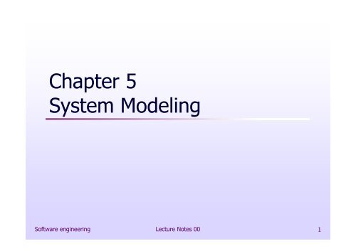
Chapter 5 System Modeling
Chapter 5 System Modeling
Chapter 5 System Modeling

You also want an ePaper? Increase the reach of your titles
YUMPU automatically turns print PDFs into web optimized ePapers that Google loves.
<strong>Chapter</strong> 5<strong>System</strong> <strong>Modeling</strong>Software engineering Lecture Notes 00 1
Topics covered Context models Interaction models Structural models Behavioral models Model-driven engineeringSoftware engineering Lecture Notes 00 2
<strong>System</strong> modeling <strong>System</strong> modeling is the process of developingabstract models of a system, with each modelpresenting a different view or perspective of thatsystem. <strong>System</strong> modeling has now come to meanrepresenting a system using some kind of graphicalnotation, which is now almost always based onnotations in the Unified <strong>Modeling</strong> Language (UML). <strong>System</strong> modelling helps the analyst to understandthe functionality of the system and models areused to communicate with customers.Software engineering Lecture Notes 00 3
Existing and planned system models Models of the existing system are used during requirementsengineering. They help clarify what the existing systemdoes and can be used as a basis for discussing its strengthsand weaknesses. These then lead to requirements for thenew system. Models of the new system are used during requirementsengineering to help explain the proposed requirements toother system stakeholders. Engineers use these models todiscuss design proposals and to document the system forimplementation. In a model-driven engineering process, it is possible togenerate a complete or partial system implementation fromthe system model.Software engineering Lecture Notes 00 4
<strong>System</strong> perspectives An external perspective, where you model thecontext or environment of the system. An interaction perspective, where you model theinteractions between a system and its environment,or between the components of a system. A structural perspective, where you model theorganization of a system or the structure of thedata that is processed by the system. A behavioral perspective, where you model thedynamic behavior of the system and how itresponds to events.Software engineering Lecture Notes 00 5
UML diagram types Activity diagrams, which show the activitiesinvolved in a process or in data processing . Use case diagrams, which show the interactionsbetween a system and its environment. Sequence diagrams, which show interactionsbetween actors and the system and betweensystem components. Class diagrams, which show the object classes inthe system and the associations between theseclasses. State diagrams, which show how the system reactsto internal and external events.Software engineering Lecture Notes 00 6
Use of graphical models As a means of facilitating discussion aboutan existing or proposed systemIncomplete and incorrect models are OK as theirrole is to support discussion. As a way of documenting an existing systemModels should be an accurate representation ofthe system but need not be complete. As a detailed system description that can beused to generate a system implementationModels have to be both correct and complete.Software engineering Lecture Notes 00 7
Context models Context models are used to illustrate theoperational context of a system - they showwhat lies outside the system boundaries. Social and organisational concerns mayaffect the decision on where to positionsystem boundaries. Architectural models show the system andits relationship with other systems.Software engineering Lecture Notes 00 8
<strong>System</strong> boundaries <strong>System</strong> boundaries are established to define whatis inside and what is outside the system.They show other systems that are used or depend onthe system being developed. The position of the system boundary has aprofound effect on the system requirements. Defining a system boundary is a political judgmentThere may be pressures to develop system boundariesthat increase / decrease the influence or workload ofdifferent parts of an organization.Software engineering Lecture Notes 00 9
The context of the MHC-PMSFig. 5.1: A simple context modelSoftware engineering Lecture Notes 00 10
Process perspective Context models simply show the othersystems in the environment, not how thesystem being developed is used in thatenvironment. Process models reveal how the system beingdeveloped is used in broader businessprocesses. UML activity diagrams may be used to definebusiness process models.Software engineering Lecture Notes 00 11
Process model ofinvoluntary detentionactivity coordinationstartactivitiesendFig. 5.2: UML activity diagramSoftware engineering Lecture Notes 00 12
Interaction models <strong>Modeling</strong> user interaction is important as it helps toidentify user requirements. <strong>Modeling</strong> system-to-system interaction highlightsthe communication problems that may arise. <strong>Modeling</strong> component interaction helps usunderstand if a proposed system structure is likelyto deliver the required system performance anddependability. Use case diagrams and sequence diagrams may beused for interaction modeling.Software engineering Lecture Notes 00 13
Use case modeling Use cases were developed originally to supportrequirements elicitation and now incorporated intothe UML. Each use case represents a discrete task thatinvolves external interaction with a system. Actors in a use case may be people or othersystems. Represented diagramatically to provide anoverview of the use case and in a more detailedtextual form.Software engineering Lecture Notes 00 14
Transfer-data use case A use case in the MHC-PMSinformal usage of directional arrowsFig. 5.3: A use caseSoftware engineering Lecture Notes 00 15
Tabular description of the‘Transfer data’ use-caseMHC-PMS: Transfer dataActorsDescriptionDataStimulusResponseMedical receptionist, patient records system (PRS)A receptionist may transfer data from the MHC-PMS to ageneral patient record database that is maintained by ahealth authority. The information transferred may eitherbe updated personal information (address, phonenumber, etc.) or a summary of the patient’s diagnosisand treatment.Patient’s personal information, treatment summaryUser command issued by medical receptionistConfirmation that PRS has been updatedComments The receptionist must have appropriate securitypermissions to access the patient information and thePRS.Fig. 5.4: Tabular description of use caseSoftware engineering Lecture Notes 00 16
Use cases in the MHC-PMS involvingthe role ‘Medical Receptionist’Fig. 5.5: Use cases for an actorSoftware engineering Lecture Notes 00 17
Sequence diagrams Sequence diagrams are part of the UML and areused to model the interactions between theactors and the objects within a system. A sequence diagram shows the sequence ofinteractions that take place during a particularuse case or use case instance. The objects and actors involved are listed alongthe top of the diagram, with a dotted line drawnvertically from these. Interactions between objects are indicated byannotated arrows.Software engineering Lecture Notes 00 18
Sequence diagram forView patient informationobjects and actorsFig. 5.6: Sequence diagramSoftware engineering Lecture Notes 00 19
Sequence diagram forTransfer DataFig. 5.7: Sequence diagramSoftware engineering Lecture Notes 00 20
Structural models Structural models of software display theorganization of a system in terms of thecomponents that make up that system and theirrelationships. Structural models may be static models, whichshow the structure of the system design, ordynamic models, which show the organization ofthe system when it is executing. You create structural models of a system when youare discussing and designing the systemarchitecture.Software engineering Lecture Notes 00 21
Class diagrams Class diagrams are used when developing an objectorientedsystem model to show the classes in a system andthe associations between these classes. An object class can be thought of as a general definition ofone kind of system object. An association is a link between classes that indicates thatthere is some relationship between these classes. When you are developing models during the early stages ofthe software engineering process, objects representsomething in the real world, such as a patient, aprescription, doctor, etc.Software engineering Lecture Notes 00 22
UML classes and association1:1 associationFig. 5.8: UML class and associationSoftware engineering Lecture Notes 00 23
Classes and associationsin the MHC-PMSFig. 5.9: UML class and associationSoftware engineering Lecture Notes 00 24
The Consultation classFig. 5.10: consultation classwith attributions and operationsSoftware engineering Lecture Notes 00 25
Generalization Generalization is an everyday technique that weuse to manage complexity. Rather than learn the detailed characteristics ofevery entity that we experience, we place theseentities in more general classes (animals, cars,houses, etc.) and learn the characteristics of theseclasses. This allows us to infer that different members ofthese classes have some common characteristicse.g. squirrels and rats are rodents.Software engineering Lecture Notes 00 26
Generalization In modeling systems, it is often useful to examine theclasses in a system to see if there is scope forgeneralization. If changes are proposed, then you do nothave to look at all classes in the system to see if they areaffected by the change. In object-oriented languages, such as Java, generalizationis implemented using the class inheritance mechanismsbuilt into the language. In a generalization, the attributes and operations associatedwith higher-level classes are also associated with the lowerlevelclasses. The lower-level classes are subclasses inherit the attributesand operations from their superclasses. These lower-levelclasses then add more specific attributes and operations.Software engineering Lecture Notes 00 27
A generalization hierarchyFig. 5.11: Generalization hierarchySoftware engineering Lecture Notes 00 28
A generalization hierarchywith added detailFig. 5.12: Generalization hierarchySoftware engineering Lecture Notes 00 29
Object class aggregation models An aggregation model shows how classesthat are collections are composed of otherclasses. Aggregation models are similar to the part-ofrelationship in semantic data models.Software engineering Lecture Notes 00 30
The aggregation associationFig. 5.13: Aggregation associationSoftware engineering Lecture Notes 00 31
Key pointsA model is an abstract view of a system that ignores system details.Complementary system models can be developed to show the system’scontext, interactions, structure and behavior.Context models show how a system that is being modeled is positionedin an environment with other systems and processes.Use case diagrams and sequence diagrams are used to describe theinteractions between users and systems in the system being designed.Use cases describe interactions between a system and external actors;sequence diagrams add more information to these by showinginteractions between system objects.Structural models show the organization and architecture of a system.Class diagrams are used to define the static structure of classes in asystem and their associations.Software engineering Lecture Notes 00 32
<strong>System</strong> <strong>Modeling</strong>Software engineering Lecture Notes 00 33
Behavioral models Behavioral models are models of the dynamicbehavior of a system as it is executing. They showwhat happens or what is supposed to happenwhen a system responds to a stimulus from itsenvironment. You can think of these stimuli as being of twotypes:Data Some data arrives that has to be processed by thesystem.Events Some event happens that triggers systemprocessing. Events may have associated data, althoughthis is not always the case.Software engineering Lecture Notes 00 34
Data-driven modeling Many business systems are data-processingsystems that are primarily driven by data. They arecontrolled by the data input to the system, withrelatively little external event processing. Data-driven models show the sequence of actionsinvolved in processing input data and generatingan associated output. They are particularly useful during the analysis ofrequirements as they can be used to show end-toendprocessing in a system.Software engineering Lecture Notes 00 35
An activity model of the insulinpump’s operationSoftware engineering Lecture Notes 00 36
Order processingSoftware engineering Lecture Notes 00 37
Event-driven modeling Real-time systems are often event-driven, withminimal data processing. For example, a landlinephone switching system responds to events suchas ‘receiver off hook’ by generating a dial tone. Event-driven modeling shows how a systemresponds to external and internal events. It is based on the assumption that a system has afinite number of states and that events (stimuli)may cause a transition from one state to another.Software engineering Lecture Notes 00 38
State machine models These model the behaviour of the system inresponse to external and internal events. They show the system’s responses to stimuli so areoften used for modelling real-time systems. State machine models show system states asnodes and events as arcs between these nodes.When an event occurs, the system moves from onestate to another. Statecharts are an integral part of the UML and areused to represent state machine models.Software engineering Lecture Notes 00 39
State diagram of amicrowave ovenSoftware engineering Lecture Notes 00 40
States and stimuli for themicrowave oven (a)StateWaitingHalf powerFull powerSet timeDisabledEnabledOperationDescriptionThe oven is waiting for input. The display shows the current time.The oven power is set to 300 watts. The display shows ‘Half power’.The oven power is set to 600 watts. The display shows ‘Full power’.The cooking time is set to the user’s input value. The display showsthe cooking time selected and is updated as the time is set.Oven operation is disabled for safety. Interior oven light is on.Display shows ‘Not ready’.Oven operation is enabled. Interior oven light is off. Display shows‘Ready to cook’.Oven in operation. Interior oven light is on. Display shows the timercountdown. On completion of cooking, the buzzer is sounded for fiveseconds. Oven light is on. Display shows ‘Cooking complete’ whilebuzzer is sounding.Software engineering Lecture Notes 00 41
States and stimuli for themicrowave oven (b)StimulusHalf powerFull powerTimerNumberDoor openDoor closedStartCancelDescriptionThe user has pressed the half-power button.The user has pressed the full-power button.The user has pressed one of the timer buttons.The user has pressed a numeric key.The oven door switch is not closed.The oven door switch is closed.The user has pressed the Start button.The user has pressed the Cancel button.Software engineering Lecture Notes 00 42
Microwave oven operationSoftware engineering Lecture Notes 00 43
Model-driven engineering Model-driven engineering (MDE) is an approach tosoftware development where models rather thanprograms are the principal outputs of thedevelopment process. The programs that execute on ahardware/software platform are then generatedautomatically from the models. Proponents of MDE argue that this raises the levelof abstraction in software engineering so thatengineers no longer have to be concerned withprogramming language details or the specifics ofexecution platforms.Software engineering Lecture Notes 00 44
Usage of model-driven engineering Model-driven engineering is still at an early stage ofdevelopment, and it is unclear whether or not it will have asignificant effect on software engineering practice. ProsAllows systems to be considered at higher levels of abstractionGenerating code automatically means that it is cheaper to adaptsystems to new platforms. ConsModels for abstraction and not necessarily right for implementation.Savings from generating code may be outweighed by the costs ofdeveloping translators for new platforms.Software engineering Lecture Notes 00 45
Model driven architecture Model-driven architecture (MDA) was the precursorof more general model-driven engineering MDA is a model-focused approach to softwaredesign and implementation that uses a subset ofUML models to describe a system. Models at different levels of abstraction are created.From a high-level, platform independent model, itis possible, in principle, to generate a workingprogram without manual intervention.Software engineering Lecture Notes 00 46
Types of model A computation independent model (CIM)These model the important domain abstractions used in a system.CIMs are sometimes called domain models. A platform independent model (PIM)These model the operation of the system without reference to itsimplementation. The PIM is usually described using UML models thatshow the static system structure and how it responds to externaland internal events. Platform specific models (PSM)These are transformations of the platform-independent model with aseparate PSM for each application platform. In principle, there maybe layers of PSM, with each layer adding some platform-specificdetail.Software engineering Lecture Notes 00 47
MDA transformationsSoftware engineering Lecture Notes 00 48
Multiple platform-specific modelsSoftware engineering Lecture Notes 00 49
Agile methods and MDA The developers of MDA claim that it is intended tosupport an iterative approach to development andso can be used within agile methods. The notion of extensive up-front modelingcontradicts the fundamental ideas in the agilemanifesto and I suspect that few agile developersfeel comfortable with model-driven engineering. If transformations can be completely automatedand a complete program generated from a PIM,then, in principle, MDA could be used in an agiledevelopment process as no separate coding wouldbe required.Software engineering Lecture Notes 00 50
Executable UML The fundamental notion behind modeldrivenengineering is that completelyautomated transformation of models to codeshould be possible. This is possible using a subset of UML 2,called Executable UML or xUML.Software engineering Lecture Notes 00 51
Features of executable UML To create an executable subset of UML, the number ofmodel types has therefore been dramatically reduced tothese 3 key types:Domain models that identify the principal concerns in a system.They are defined using UML class diagrams and include objects,attributes and associations.Class models in which classes are defined, along with their attributesand operations.State models in which a state diagram is associated with each classand is used to describe the life cycle of the class. The dynamic behavior of the system may be specifieddeclaratively using the object constraint language (OCL), ormay be expressed using UML’s action language.Software engineering Lecture Notes 00 52
Key points Behavioral models are used to describe the dynamicbehavior of an executing system. This behavior can bemodeled from the perspective of the data processed by thesystem, or by the events that stimulate responses from asystem. Activity diagrams may be used to model the processing ofdata, where each activity represents one process step. State diagrams are used to model a system’s behavior inresponse to internal or external events. Model-driven engineering is an approach to softwaredevelopment in which a system is represented as a set ofmodels that can be automatically transformed to executablecode.Software engineering Lecture Notes 00 53