MET ONE HHPC-6 Handheld Airborne Particle ... - Particle Counters
MET ONE HHPC-6 Handheld Airborne Particle ... - Particle Counters
MET ONE HHPC-6 Handheld Airborne Particle ... - Particle Counters

Create successful ePaper yourself
Turn your PDF publications into a flip-book with our unique Google optimized e-Paper software.
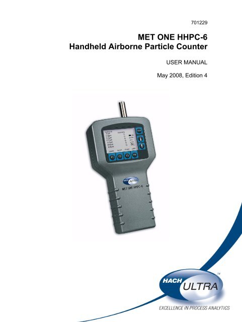
701229<strong>MET</strong> <strong>ONE</strong> <strong>HHPC</strong>-6<strong>Handheld</strong> <strong>Airborne</strong> <strong>Particle</strong> CounterUSER MANUALMay 2008, Edition 4
701229<strong>MET</strong> <strong>ONE</strong> <strong>HHPC</strong>-6<strong>Handheld</strong> <strong>Airborne</strong> <strong>Particle</strong> CounterUSER MANUALMay 2008, Edition 4© Hach Ultra Analytics, Inc., 2008. All rights reserved. Printed in the U.S.A.
Table of ContentsSection 1 Specifications.................................................................................................................... 5Section 2 General Information......................................................................................................... 72.1 Safety information........................................................................................................................ 72.1.1 Use of hazard information................................................................................................... 72.1.2 Precautionary labels ........................................................................................................... 72.1.3 Electrostatic discharge (ESD) considerations..................................................................... 82.1.4 Battery safety information ................................................................................................... 82.2 General product information ........................................................................................................ 8Section 3 Installation........................................................................................................................ 113.1 Unpack the instrument............................................................................................................... 113.2 Installation guidelines for the <strong>MET</strong> <strong>ONE</strong> <strong>HHPC</strong>–6..................................................................... 123.3 Mechanical installation............................................................................................................... 123.3.1 Install the isokinetic probe................................................................................................. 123.3.2 Install the intake hose barb ...............................................................................................123.3.3 Install the zero count filter ................................................................................................. 133.3.4 Connect the AC/DC power supply .................................................................................... 14Section 4 Operation.......................................................................................................................... 154.1 Install the <strong>MET</strong> <strong>ONE</strong> <strong>HHPC</strong>–6 Utility software........................................................................... 154.2 Power up.................................................................................................................................... 154.3 LCD and keypad ........................................................................................................................ 154.3.1 Keypad.............................................................................................................................. 164.3.2 Displays/screens............................................................................................................... 164.4 Factory default settings.............................................................................................................. 184.5 Configuration setup.................................................................................................................... 184.6 Custom settings ......................................................................................................................... 184.6.1 Set the count mode........................................................................................................... 184.6.2 Set the sample time or volume ......................................................................................... 194.6.3 Set the method for counting data...................................................................................... 214.6.4 Set the number of samples ............................................................................................... 224.6.5 Set password protection ................................................................................................... 224.6.6 Set the alarm count and size ............................................................................................ 254.6.7 Select input/output (I/O) port.............................................................................................254.6.8 Set the temperature .......................................................................................................... 254.6.9 Set buffer count................................................................................................................. 264.6.10 Set the clock date and time............................................................................................. 264.6.11 Edit labels ....................................................................................................................... 274.7 Counter operation ...................................................................................................................... 294.7.1 Verify the <strong>MET</strong> <strong>ONE</strong> <strong>HHPC</strong>–6 with a zero count filter ...................................................... 294.7.2 Collect samples................................................................................................................. 304.7.3 Transfer sample data to PC .............................................................................................. 304.7.4 Print sample data .............................................................................................................. 314.7.5 Store sample data............................................................................................................. 31Section 5 Maintenance .................................................................................................................... 335.1 Battery maintenance.................................................................................................................. 335.1.1 Charge a drained battery .................................................................................................. 335.2 Calibrate the <strong>MET</strong> <strong>ONE</strong> <strong>HHPC</strong>–6 .............................................................................................. 33Section 6 Troubleshooting ............................................................................................................. 356.1 Problems and recommendations ............................................................................................... 356.2 Restore default settings ............................................................................................................. 363
Table of ContentsSection 7 Replacement Parts and Accessories .........................................................................377.1 Accessories ................................................................................................................................377.2 Optional accessories ..................................................................................................................37Section 8 Service Contact Information ........................................................................................39Section 9 Limited Warranty.............................................................................................................40Section 10 Certification....................................................................................................................41Appendix A Data Communications...............................................................................................43A.1 Remote serial interface (I/O port)...............................................................................................43A.1.1 DB9 serial connection .......................................................................................................43Index ......................................................................................................................................................454
Section 1SpecificationsSpecifications are subject to change without notice.InstrumentDimensions (W x L x H) 114.3 mm x 209.6 mm x 57.2 mm (4.5" x 8.25" x 2.25")Weight1.0 kg (2.2 lb)Number of size channelsSixStandard 0.3, 0.5, 0.7, 1.0, 2.0, 5.0 µmIAQ 0.5, 0.7, 1.0, 2.0, 5.0, 10.0 µmCustom0.3 to 20 µm availableFlow rate0.1 cfm (2.83 L/min)Light sourceLaser diode; index guided (26,000 MTBF at 25 °C)CalibrationPSL particles in air (NIST traceable)Counting efficiency50% at 0.3 µm; 100% for particles > 0.45 µm (per JIS B9921:1997)Zero count1 count/5 minute (per JIS B9921:1997)Coincidence loss5% at 2,000,000 particles per cubic footRelative humidity± 7%, 20% to 90%, non-condensingTemperature± 3 °C, 10 °C to 40 °C (50 °F to 104 °F)Data storage500 sample records (rotating buffer)Data recordedDate, time, counts, relative humidity, temperature, sample volumes, alarms, labelDisplayGraphic liquid crystal with back lightAlarmsCounts, low battery, sensor failCount modesConcentration, totalize, audioDelay time0 to 24 hoursSample inletIsokinetic probeInterfaceRS232 and RS485 through RJ45Vacuum sourceInternal pump (flow controlled)HousingInjection molded plasticPowerAC Adapter, 12 VDC at 2.5 A, 90 to 250 VAC, 50 to 60 HzRechargeable batteryNiMH, 4.8 V at 4.5 Ah; replaceableRecharge time2 hoursContinuous operating time8 hoursStandards CE, JIS B9921: 1997EnvironmentOperating temperatureOperating humidityStorage temperatureStorage humidityComplianceStandards10 °C to 40 °C (50 °F to 104 °F)20% to 90%, non-condensing–10 °C to 50 °C (14 °F to 122 °F)Up to 90%, non-condensingJIS B 9921–1997—Light Scattering Automatic <strong>Particle</strong> CounterFederal Standard 209E—Standard Practice for Defining Size Calibration,Resolution and Counting Accuracy of an Air-Borne <strong>Particle</strong> Counter UsingNear-Monodispersed Spherical Particulate Material.5
Specifications6
Section 2General Information2.1 Safety information2.1.1 Use of hazard information2.1.2 Precautionary labelsRead this entire manual before unpacking, setting up or operating this equipment. Payattention to all danger and caution statements. Failure to do so could result in seriousinjury to the operator or damage to the equipment.To make sure that the protection provided by this equipment is not impaired, do not useor install this equipment in any manner other than that specified in this manual.DANGERIndicates a potentially or imminently hazardous situation which, if not avoided, willresult in death or serious injury.WARNINGIndicates a potentially or imminently hazardous situation which, if not avoided,could result in death or serious injury.CAUTIONIndicates a potentially hazardous situation that can result in minor ormoderate injury.Important Note: Indicates a situation which, if not avoided, can cause damage to theinstrument. Information that requires special emphasis.Note: Information that supplements points in the main text.Read all labels and tags attached to the instrument. Personal injury or damage to theinstrument could occur if not observed. A symbol, if noted on the instrument, will beincluded with a danger or caution statement in the manual.This symbol, if noted on the instrument, references the instruction manual for operation and/or safety information.Electrical equipment marked with this symbol cannot be disposed of in European public disposal systems after12 August of 2005. In conformity with European local and national regulations (EU Directive 2002/96/EC),European electrical equipment users must now return old or end-of life equipment to the Producer for disposal at nocharge to the user.Note: To return for recycling, contact the equipment producer or supplier for instructions on how to return end-of-lifeequipment, producer-supplied electrical accessories and all auxiliary items for proper disposal.This symbol, when noted on a product enclosure or barrier, indicates that a risk of electrical shock and/orelectrocution exists.This symbol, if noted on the product, indicates the need for protective eye wear.This symbol, when noted on the product, identifies the location of a fuse or current limiting device.This symbol indicates a laser device is used in the equipment.This symbol, when noted on the product, indicated the presence of devices sensitive to Electro-static Discharge(ESD) and indicated that care must be taken to prevent damage with the equipment.7
General Information2.1.3 Electrostatic discharge (ESD) considerations2.1.4 Battery safety informationImportant Note: To minimize hazards and ESD risks, maintenance procedures that donot require power to the particle counter should be performed with power removed.Delicate internal electronic components can be damaged by static electricity, resulting indegraded instrument performance or eventual failure.The manufacturer recommends taking the following steps to prevent ESD damage tothe instrument:• Before touching any instrument electronic components (such as printed circuit cardsand the components on them) discharge static electricity. Touch an earth-groundedmetal surface such as the chassis of an instrument or a metal conduit or pipe.• To reduce static build-up, avoid excessive movement. Transport static-sensitivecomponents in anti-static containers or packaging.• To discharge static electricity and keep it discharged, wear a wrist strap connected bya wire to the earth ground.• Handle all static-sensitive components in a static-safe area. If possible, use anti-staticfloor pads and work bench pads.WARNINGAn explosion can occur if the internal battery is replaced incorrectly.Figure 1 shows the label that appears on the battery for the safety of the user.Figure 1 Battery safety label2.2 General product informationThe <strong>MET</strong> <strong>ONE</strong> <strong>Handheld</strong> <strong>Airborne</strong> <strong>Particle</strong> Counter–6 (<strong>MET</strong> <strong>ONE</strong> <strong>HHPC</strong>–6) (refer toFigure 2 on page 9) is a portable instrument that measures, counts, stores and reportsairborne particulates. The standard <strong>MET</strong> <strong>ONE</strong> <strong>HHPC</strong>–6 can hold 500 samples in thememory. The data records include the date, time, counts, sample labels, volume, alarmflags, temperature and relative humidity. Use the interface cable and software providedwith the <strong>MET</strong> <strong>ONE</strong> <strong>HHPC</strong>–6 to download the data records to a personal computer (PC).The internal battery can power the <strong>MET</strong> <strong>ONE</strong> <strong>HHPC</strong>–6 when the <strong>MET</strong> <strong>ONE</strong> <strong>HHPC</strong>–6 ismobile. The <strong>MET</strong> <strong>ONE</strong> <strong>HHPC</strong>–6 can also be connected to an AC power adapterprovided, for extended or stationary sampling.The <strong>MET</strong> <strong>ONE</strong> <strong>HHPC</strong>–6 is commonly used for the following:• To monitor the air quality in clean-rooms, manufacturing processes andpharmaceutical production• For mold remediation• For Indoor Air Quality (IAQ) monitoringNote: Option EX enables the <strong>MET</strong> <strong>ONE</strong> <strong>HHPC</strong>–6 to store up to 2000 sample records. This optioncan only be added at the factory.8
General InformationFigure 2 <strong>MET</strong> <strong>ONE</strong> <strong>HHPC</strong>–61 Front view 3 Back view2 Bottom view9
General Information10
Section 3Installation3.1 Unpack the instrumentDANGEROnly qualified personnel should conduct the tasks described in this section ofthe manual.Remove the components from the shipping container and inspect for damage. Verify thatall the items listed in Figure 3 are included. If any items are missing or damaged, contactthe manufacturer or sales representative.Retain the original packaging materials. Use the original packaging material to store orship the instrument to protect against damage during storage or transportation.Figure 3 List of packaged items1 <strong>MET</strong> <strong>ONE</strong> <strong>HHPC</strong>–6 6 RJ45 to DB9 adaptor (SA000070–01)2 Zero count filter 7 RS232 modular cable (VP894408)3 Intake nozzle, 1/8” hose barb (P000026–01) 8 6¼”–OD high purity tubing (VP792002)4 Isokinetic probe cap 9 US power cord (VP623501)5 AC/DC power supply (VP624005) 10 Utility software diskette (CS200020–01)11
Installation3.2 Installation guidelines for the <strong>MET</strong> <strong>ONE</strong> <strong>HHPC</strong>–63.3 Mechanical installation3.3.1 Install the isokinetic probe3.3.2 Install the intake hose barbThe <strong>MET</strong> <strong>ONE</strong> <strong>HHPC</strong>–6 is ready to use when shipped and has default configurationsettings (section 4.4 on page 18). Refer to the general guidelines during installation:1. Lift the <strong>MET</strong> <strong>ONE</strong> <strong>HHPC</strong>–6 from the shipping container or the carrying case andplace it on a flat surface.2. Remove the layer of protective plastic from the LCD screen3. Remove the isokinetic probe cover (black plastic cap) before the startup.Note: The pump and other internal electrical components will be damaged if the cap is left on.The <strong>MET</strong> <strong>ONE</strong> <strong>HHPC</strong>–6 is shipped with two different intake devices:• Isokinetic probe• Intake hose barbImportant Note: Do not use a wrench to connect or disconnect the intake nozzle orisokinetic probe. Finger-tighten the connection.The isokinetic probe (refer to Figure 4 on page 13) is used to sample ambient airsamples. The isokinetic probe is pre-installed and ready for use as soon as the <strong>MET</strong> <strong>ONE</strong><strong>HHPC</strong>–6 is unpacked. To install the isokinetic probe:1. Attach the isokinetic probe to the intake nozzle on the <strong>MET</strong> <strong>ONE</strong> <strong>HHPC</strong>–6 by turningthe isokinetic probe to the right.2. Remove the black plastic cap attached to the isokinetic probe.Note: Make sure that the cap is attached to the isokinetic probe when the probe is not in use.The cap protects the <strong>MET</strong> <strong>ONE</strong> <strong>HHPC</strong>–6 from debris and contamination.To sample areas that are difficult to reach, connect longer tubing to the isokinetic probewith a hose barb end.Note: Use a maximum of four feet of high purity or approved tubing only. Incorrect size or type oftubing will affect the sample accuracy.Connect the intake hose barb (refer to Figure 4 on page 13) to the <strong>MET</strong> <strong>ONE</strong> <strong>HHPC</strong>–6for zero counting and purging or to sample areas that are difficult to reach.To install the intake hose barb:1. Unscrew the isokinetic probe from the <strong>MET</strong> <strong>ONE</strong> <strong>HHPC</strong>–6.2. Attach the hose barb to the <strong>MET</strong> <strong>ONE</strong> <strong>HHPC</strong>–6.3. Remove the protective cap of the intake hose barb.12
InstallationFigure 4 Isokinetic probe with tubing and zero count filter1 Hose barb fitting 3 Tubing2 Isokinetic probe 4 <strong>MET</strong> <strong>ONE</strong> <strong>HHPC</strong>–63.3.3 Install the zero count filterIn a clean-room application, the zero count filter (refer to Figure 3 on page 11, item 2)verifies that the <strong>MET</strong> <strong>ONE</strong> <strong>HHPC</strong>–6 is not counting electrical noise signals from internalcomponents and is not subject to external interference. In indoor air quality and otherapplications, the zero count filter cleans out the sensor immediately after a highconcentration sampling.To connect the zero count filter:1. Remove the isokinetic probe from the <strong>MET</strong> <strong>ONE</strong> <strong>HHPC</strong>–6.2. Secure one end of the 6-inch high purity to the intake hose barb.3. Secure the opposite end of the 6-inch high purity tubing to the zero count filter.Note: Make sure that the arrow of airflow direction or the indicator on the zero count filter pointstowards the tubing.13
Installation3.3.4 Connect the AC/DC power supplyImportant Note: Do not use a power supply unit that does not supply the required voltageand charging current (polarity) to operate the <strong>MET</strong> <strong>ONE</strong> <strong>HHPC</strong>–6.To connect the external power supply:1. Turn off power.2. Plug one end of the power cord into the external power supply and the other end intoan electrical wall receptacle.3. Plug the external power supply jack into the power port (refer to Figure 5).1 Power portFigure 5 Location of power port14
Section 4Operation4.1 Install the <strong>MET</strong> <strong>ONE</strong> <strong>HHPC</strong>–6 Utility software1. Plug one end of the modular cable (VP894408) to the <strong>MET</strong> <strong>ONE</strong> <strong>HHPC</strong>-6. Plug theopposite end of the modular cable to the DB9 to RJ45 adapter.2. Plug the DB9 to RJ45 adapter (SA000070–01) to the RS232 serial communicationport on the PC. If the PC does not have an RS232 serial communication port, plugthe DB9 to RJ45 adapter to the USB to RS232 adapter.3. Insert the <strong>MET</strong> <strong>ONE</strong> <strong>HHPC</strong>–6 Utility software diskette into the drive.4. Copy <strong>HHPC</strong>6 Utility.exe and <strong>HHPC</strong>6.ini to a working directory on the PC. If thecommunications port to be used is other than Com1, open <strong>HHPC</strong>6.ini and changePort=Com1 to Port=ComX (where X represents the number of the port to use.)5. To open the Utility software, double-click the <strong>HHPC</strong>6 Utility.exe file. The <strong>MET</strong> <strong>ONE</strong><strong>HHPC</strong>–6 Utility window is displayed (refer to Figure 6).6. Follow the instructions in the Readme.txt file on the diskette to install the software.Figure 6 <strong>MET</strong> <strong>ONE</strong> <strong>HHPC</strong>–6 Utility window4.2 Power upPress the POWER button on the right of the display to turn on the <strong>MET</strong> <strong>ONE</strong> <strong>HHPC</strong>–6.When the <strong>MET</strong> <strong>ONE</strong> <strong>HHPC</strong>–6 is powered on, the <strong>MET</strong> <strong>ONE</strong> Opening screen is displayedbriefly followed by the Main screen.4.3 LCD and keypadThe <strong>MET</strong> <strong>ONE</strong> <strong>HHPC</strong>–6 has a Liquid Crystal Display (LCD) with a keypad on the rightand bottom of the display.Note: If the <strong>MET</strong> <strong>ONE</strong> <strong>HHPC</strong>–6 does not power up, double-check the AC connection or the batterypower. To charge the battery, refer to section 5.1 on page 33.15
Operation4.3.1 KeypadImportant Note: Do not use the <strong>MET</strong> <strong>ONE</strong> <strong>HHPC</strong>–6 stand when operating the keypad.The <strong>MET</strong> <strong>ONE</strong> <strong>HHPC</strong>–6 keypad (refer to Figure 7) contains the following:• Function keys• F1—Starts and stops the sample• F2—Selects the setup screen• F3—Selects the Date, Time and Delay Screen• F4—Selects the sample label screenThe function keys are also used to select the various screens available.• POWER buttons• On• Off• UP and DOWN arrow keysThe UP and DOWN arrow keys are used to scroll within the selected screen. The UPand DOWN arrow keys also change the LCD contrast of the Main screenFigure 7 Keypad1 Display screen 4 DOWN arrow key2 POWER button 5 Function keys3 UP arrow key4.3.2 Displays/screensPress the corresponding button from the keypad at the bottom of the LCD to invoke thefollowing screens:• Main screen• Setup screen• Clock setup screen• Label menu screen16
4.3.2.1 Main screen4.3.2.2 Setup screen4.3.2.3 Clock setup screen4.3.2.4 Label menu screenOperationThe following information is displayed in the Main screen:• Channel sizes and corresponding counts• Sample air relative humidity (% RH)• Sample air temperature (°C or °F)• Battery charge indicator (amount of charge remaining in the battery, refer to Table 6on page 33)• Sampled volume indicator (clock timer symbol)• Selected sample volumeThe following information is displayed in page 1 of the Setup screen:• Type of count mode (Concentration, Totalize or Audio)• Sample volume (in L) or sample time (in seconds or minutes)• Type of count date (Cumulative or Differential)• Number of samples• Status of password (Enabled or Disabled) 2The following information is displayed in page 2 of the Setup screen:• Alarm limit (1 to 100,000)• Alarm size (size of particles)• Input/output port (Printer, Print buffer or Serial 9600)• Temperature (°C or °F)• Buffer count (number of samples stored in the buffer)The following information is displayed in Clock setup screen:• Date (MM/DD/YYYY or DD/MM/YYYY)• Time (HH:MM:SS)• Delay time (HH:MM:SS)The following information is displayed in Clock setup screen:• List of location labels17
Operation4.4 Factory default settingsTable 1 provides the default settings for the <strong>MET</strong> <strong>ONE</strong> <strong>HHPC</strong>–6.Table 1 Default settingsParameterDefault settingCount modeConcentrationSample volume1.0 LCount dataCumulativeNumber of samples 1Alarm limit 0Alarm size1st channelI/O portPrinterTemperature °CBuffer count 0Label location 14.5 Configuration setup4.6 Custom settings4.6.1 Set the count modeOnce the <strong>MET</strong> <strong>ONE</strong> <strong>HHPC</strong>–6 is unpacked and connected to the appropriate intakedevice, use the default settings to conduct a 1-minute count cycle. Download the data toa PC and print the results.To reset the <strong>MET</strong> <strong>ONE</strong> <strong>HHPC</strong>–6 to the default settings:1. Hold down the F1 key and press the POWER button.2. Release the F1 key when the message “Defaulting data” is displayed on the screen.To perform a 1-minute count cycle:1. Remove the isokinetic probe cover (black plastic cap).2. Press the POWER button to turn on the <strong>MET</strong> <strong>ONE</strong> <strong>HHPC</strong>–6.3. Press F1 (Count) on the Main screen. The count cycle begins and the display aboveF1 changes to “RUN”. After one minute, the count cycle concludes and the displayabove F1 changes to “COUNT”. The results are saved automatically in the printbuffer. Refer to section 4.7.3 on page 30 to transfer the data to a PC and printthe results.Change the factory-set default settings as needed for a specific application beforesampling. Use the function (F1 to F4) and arrow keys on the keypad to customize thesettings as required.To set the count mode:1. Press F2 (Setup) on the Main screen. The Setup Page 1 screen is displayed with thecurrent Count Mode field selected (refer to Figure 8 on page 19).2. Press F3 (Right arrow) to view the count modes available.18
OperationTable 2 provides a description of the various count modes that are available.Table 2 Count modesMode Description ExampleConcentrationTotalizeAudioThe Concentration mode is used to take a quick snapshot ofairborne particulate samples, especially in areas whereparticulate levels are unknown and may exceed theoperating levels of the counter. The <strong>MET</strong> <strong>ONE</strong> <strong>HHPC</strong>–6estimates the count per cubic foot or liter depending on thevolume selected.The <strong>MET</strong> <strong>ONE</strong> <strong>HHPC</strong>–6 updates the displayed results bycalculating the completed sample counts and volumecompared to the balance of volume.In the Totalize mode, the particle counts are displayed andaccumulated as sampled. When the sample is completed,the record is stored and the value is displayed on the screenuntil the next sample is started.In the Audio mode, the <strong>MET</strong> <strong>ONE</strong> <strong>HHPC</strong>–6 beeps each timethe alarm limit exceeds. Refer to section 4.6.6 on page 25.If the selected volume is 0.1 cubic foot(1-minute sample) and the sample isallowed to complete, then the displayedresult is 10 times the actual sampled counts.If the same sample display was viewed atthe sixth second of sampling, the displayedresult is 100 times the actualsampled count.N/AIf the limit is set for 10, the counter beepswhen the count first reaches 10 and beepsagain for every multiple of 10.3. Press F4 (Return) to select the displayed mode and return to the Main screen.Figure 8 Setup screen, page 14.6.2 Set the sample time or volumeThe default Sample Volume setting is 1.0 L.To set the sample volume:1. Press F2 (Setup) on the Main screen. The Setup Page 1 screen is displayed with theCount Mode field selected.2. Press the DOWN arrow key to move to the Sample Time field (refer to Figure 9 onpage 20).3. Press F2 (Left arrow) and F3 (Right arrow) to scroll through all sample volume andstandard sample time selections.4. Press F4 (Return) to select the displayed selection and return to the Main screen.19
OperationFigure 9 Select sample timeUse the UP and DOWN arrow keys to select the second selection line of Sample Time orSample Volume. When Sample Time is highlighted, the display will change from “PAGE2” to “EDIT” (refer to Figure 9). The display will change back to “PAGE 2” when the cursoris moved to another line or the Sample Time is changed to Sample Volume.To set the custom sample time:1. Press F2 of F3 before the Sample Time is changed to select the sample resultsdisplay mode (refer to Figure 10 on page 20). The sample results will be displayed inLiters (L) or Cubic feet (CF).2. Press F1 (Edit). The cursor highlights the first two digits (Minutes).3. Press F3 to select Seconds.4. Use the UP or DOWN arrow keys to select the required sample time.5. Press F1 to save the change or press F4 to exit the operation. The <strong>MET</strong> <strong>ONE</strong><strong>HHPC</strong>–6 will automatically convert the selected time to volume because all sampleresults have to reference the volume sampled. For example, if Sample Time is set toCF = 02.00, the Main screen displays 0.20 CF. The volume selected is displayed inthe right column of the Main screen. Refer to Table 3 for details.Figure 10 Change sample time20
OperationSample volumeTable 3 lists the Sample Time and Volume options available.Table 3 Sample time and volume optionsSample volume1.0L 21 seconds10.0L 3.53 minutes0.01CF6 seconds1.0CF10 minutes2.83L 60 seconds28.3L 10 minutes0.10CF60 secondsManualContinuously sample until the <strong>MET</strong> <strong>ONE</strong> <strong>HHPC</strong>–6 is manuallystoppedSample Time (L) 1 second (0.05 L) to 59 minutes 59 seconds (169.85 L)Sample Time CF1 second (0.0017 cubic feet) to 59 minutes 59 seconds (6 cubicfeet)4.6.3 Set the method for counting dataTo set the method for counting data:1. Press F2 (Setup) on the Main screen. The Setup Page 1 screen is displayed with theCount Mode field selected.2. Press the DOWN arrow key to move to the Count Data field (refer to Figure 11 onpage 21).3. Press F2 (Left arrow) or F3 (Right arrow) to toggle between the following countingmethods:• Cumulative—Includes all particles that are larger than or equal to the particle sizeselected, represented by the SUM symbol.• Differential—Includes all particles that are larger than or equal to the particle sizeselected, but smaller than the next greatest particle size, represented by thedelta symbol.4. When the required method is highlighted, press F4 (Return) to select that method andreturn to the Main screen.Figure 11 Setup screen with count mode selected21
Operation4.6.4 Set the number of samplesTo set the number of samples:1. Press F2 (Setup) on the Main screen. The Setup Page 1 screen is displayed with theCount Mode field selected (refer to Figure 12 on page 22).2. Press the DOWN arrow key to move to the Number of Samples field.3. Press F3 (Right arrow) to select the number of samples until the required number isdisplayed.4. Press F4 (Return) to select that number and return to the Main screen.Note: If F2 is pressed when the number of samples is equal to one, the Number of Samples fielddisplays “INF” for continuous sampling. Press F2 (Left arrow) again for the sample count to be equalto the buffer size.Figure 12 Setup screen with number of samples selected4.6.5 Set password protectionThe password protection function is present with firmware version B and later (CatalogNo. 2087005). The Setup Password function enables a system administrator to preventusers from modifying the settings of the <strong>MET</strong> <strong>ONE</strong> <strong>HHPC</strong>–6. Once the Setup Passwordfunction is enabled, the counter allows two types of login:• System Administrator login—Has permissions to change all settings on the <strong>MET</strong> <strong>ONE</strong><strong>HHPC</strong>–6.• User login—Allows the operator to change only the location ID (label) on the Mainscreen. All other <strong>MET</strong> <strong>ONE</strong> <strong>HHPC</strong>–6 settings can only be set by the systemadministrator.22
To enable password protection:1. Press F2 (Setup) on the Main screen. The Setup Page 1 menu is displayed.OperationFigure 13 Setup screen with password selected2. Use the DOWN arrow key to scroll to the Password=Disabled field.3. Press F2 (Left arrow) or F3 (Right arrow). The Enter Password screen is displayed(refer to Figure 14 on page 23). A box prompt to enter the password is displayed.Passwords can be a minimum of one character and a maximum of eight characters.Initially, the box prompt will contain the character “A”.4. To change the character, use the UP or DOWN arrow keys to scroll through thecharacters a to z, 0 to 9, A to Z and space.5. Press F2 (Left arrow) or F3 (Right arrow) to move to the next character.6. When the password is set, press F4 (Enter) to enter the system administrator mode.Figure 14 Enter password screen4.6.5.1 Log in as the system administratorOnce the password has been enabled, the display will show a Login screen.To log in as the system administrator:1. Press F1 (Admin) or F4 (User) on the Login screen. A box prompt to enter thepassword is displayed.2. Use the UP or DOWN arrow keys to scroll through the available characters (a to z, 0to 9, A to Z and space).23
Operation4.6.5.2 Change the setup password3. Enter the correct password to login as a system administrator.4. Press either F4 (Enter) or F1 (Change) to change the password.Note: To login as an operator without programming permissions, select the F1 (User) key on thelogin screen. There is no need to enter a password.5. If the password entered is incorrect, a message “Invalid Password”. Subsequently,the <strong>MET</strong> <strong>ONE</strong> <strong>HHPC</strong>–6 will display the Login screen.To change the setup password:1. Go to the Password Entry screen.2. Press F1 (Change). The New Password screen is displayed (refer to Figure 15).3. Use the UP or DOWN arrow keys to modify the password.4. After the new password is entered, press F1 (Save) to save the settings. To cancelwithout saving the changes, press F4 (Escape).Figure 15 New password screen4.6.5.3 Disable password protectionTo disable the setup password and allow all users to modify the settings:1. Log in as the system administrator.2. Scroll to the Password= Enabled field on the Setup Page 1 screen and press F2 orF3. A message “Password=Disabled” is displayed.Any user may now login and modify the settings of the <strong>MET</strong> <strong>ONE</strong> <strong>HHPC</strong>–6.4.6.5.4 Reset the passwordIf the password of the system administrator is forgotten or lost, contact the manufacturerto receive a new password. Technical support will require the following information toissue a new password:• The serial number of the <strong>MET</strong> <strong>ONE</strong> <strong>HHPC</strong>–6.• The current date setting of the <strong>MET</strong> <strong>ONE</strong> <strong>HHPC</strong>–6 in the MMDDYYYY format, whereMM is the two-digit month, DD is the two-digit day and YYYY is the four-digit year.24
4.6.6 Set the alarm count and size4.6.7 Select input/output (I/O) portPort definition ApplicationOperationWhen the alarm is set, an audible alarm is triggered when counts reach the count limitson the selected particle size.To set the alarm count:1. Press F2 (Setup) on the Main screen. The Setup Page 1 screen is displayed.2. Press F1 (Page 2) on the Setup Page 1 screen to go to the second page of thescreen. The Setup Page 2 Screen is displayed.3. Press F3 (Right arrow) or F2 (Left arrow) in the Alarm Limit field to move forward todisplay the limits. The range for the count limit can be set from 1 to 100,000.4. When the required limit is selected, press the DOWN arrow key to move the cursor tothe Alarm Size field.5. Press F3 (Right arrow) to move forward or F2 (Left arrow) to move back to display thevarious particle sizes.6. Press F4 (Return) to accept both the particle count and size alarm settings and returnto the Main screen.Select any of the I/O port options listed in Table 4.Note: The <strong>MET</strong> <strong>ONE</strong> <strong>HHPC</strong>–6 I/O port will have the Printer option selected by default.To select the I/O port:1. Press F2 (Setup) to display the Setup Page 1 screen.2. Press F1 (Page 2) to display the Setup Page 2 screen.3. Use the DOWN arrow key to scroll down to the I/O Printer field.4. Press F2 (Left arrow) or F3 (Right arrow) to scroll through the options available.5. Press F4 to select the required option and return to the Main screen.Table 4 I/O port definitions and applicationsPrinterPrint bufferSerial 9600Select this option to connect to the Serial Thermal printer. This option is commonly used when ahard copy of the printed data is required after the completion of each sample data.Select this option to print the sample data stored in the sample buffer using the Serial Thermalprinter. This option is commonly used at the end of the sample period. This option can also beselected as and when required.Select this option to connect the <strong>MET</strong> <strong>ONE</strong> <strong>HHPC</strong>–6 to a PC.4.6.8 Set the temperatureThe temperature and relative humidity sensor is contained within the <strong>MET</strong> <strong>ONE</strong> <strong>HHPC</strong>–6.Allow the <strong>MET</strong> <strong>ONE</strong> <strong>HHPC</strong>–6 to acclimatize to the room conditions for improvedaccuracy. Temperature and relative humidity results will be displayed and stored in thebuffer at the end of each sample.To set the temperature:1. Press F2 (Setup) to display the Setup Page 1 screen.2. Press F1 (Page 2) to display the Setup Page 2 screen.3. Use the DOWN arrow key to scroll down to the Temperature field.25
Operation4.6.9 Set buffer count4.6.10 Set the clock date and time4.6.10.1 Set the date4. Press F2 (Left arrow) or F3 (Right arrow) to scroll through the two options available.5. Press F4 to select the temperature reporting method (°C or °F) and return to theMain screen.To set the buffer count:1. Press F2 (Setup) to display the Setup Page 1 screen (refer to Figure 8 on page 19).2. Press F1 (Page 2) to display the Setup Page 2 screen.3. Use the DOWN arrow key to scroll down to the Buffer Count field.4. Press F2 (Left arrow) or F3 (Right arrow) to scroll through the two options available.This menu will display the number of samples stored in the buffer (memory).5. Select Clear Buffer to delete all samples stored in the buffer. The <strong>MET</strong> <strong>ONE</strong> <strong>HHPC</strong>–6stores sample data measurements in a 500 or 2000 (EX Option) rotating buffer. The<strong>MET</strong> <strong>ONE</strong> <strong>HHPC</strong>–6 overwrites previous records when the buffer is full.Note: The <strong>MET</strong> <strong>ONE</strong> <strong>HHPC</strong>–6 deletes previous records in the buffer when the buffer is full,based on a first in, first out order.6. Press F4 (Return) to return to the Main screen.1. Press F3 (Clock) on the Main screen. The Clock Setup screen is displayed (refer toFigure 16 on page 26). The date area is selected by default or by the last changemade in the settings. The cursor indicates the current selection.2. Press F4 (Enter) to exit the screen if the information displayed is correct.3. Press F1 (Program) to make changes. The display above F4 will change to“FORMAT”. The cursor will move to the first two digits of the date.4. Press F4 (Format) to toggle the order in which the date is displayed (MM/DD/YYYY orDD/MM/YYYY).5. Press F1 to accept the changes.6. Press F4 to exit the screen.Figure 16 Clock setup screen26
Operation4.6.10.2 Set the time4.6.10.3 Set the delay timeTo change the time displayed:1. Press F3 (Clock) on the Main screen.2. Use the UP or DOWN arrow keys and move the cursor to the Time field.3. Press F1 (Program) to make changes in the selected field. The display above F4 willchange to “FORMAT”. The cursor will move to the first two digits of the time.4. Press F4 (Format) to toggle between standard and military time.5. Press F2 (Left arrow) or F3 (Right arrow) to move the cursor to hours, minutes orseconds.6. Use the UP or DOWN arrow keys to select the correct hours, minutes or seconds.7. Press F1 (Enter) to accept the changes.8. Press F4 to exit the screen.To set the delay time:1. Press F3 (Clock) on the Main screen.2. Use the UP or DOWN arrow keys to move the cursor to the Delay field.3. Press F1 (Program) to make changes in the selected field. The display will change to“FORMAT”. The cursor will move to the first two digits of the delay time (HH:MM:SS).4. Press F2 (Left arrow) or F3 (Right arrow) to move the cursor to hours, minutes orseconds.5. Use the UP or DOWN arrow keys to select the correct hours, minutes or seconds.6. Press F1 (Enter) to accept the changes.7. Press F4 to exit the screen.Note: Delay time will apply to all future multiple samples. This feature is commonly used to rununmanned multiple samples at delayed intervals.4.6.11 Edit labelsLabels can be used to identify samples or blocks of samples in different rooms orlocations without the need to download the sample data to a PC each time. Labels arealso helpful when notes cannot be maintained to correlate each sample or blocks ofsamples to the specific location.Note: The <strong>MET</strong> <strong>ONE</strong> <strong>HHPC</strong>–6 is shipped with default label names for Location 1 to Location 8.4.6.11.1 Edit labels with the keypadTo edit labels using the keypad:1. Press F4 on the Main screen to display the Label Menu screen (refer to Figure 17).2. Press F1 (Edit) to edit the first label.27
Operation3. Use the UP or DOWN arrow keys to select a label. When the cursor reaches the top orbottom label, the screen begins to scroll.Figure 17 Location menu screen4. Press F1 (Edit). A box cursor is displayed on the first letter of the label (refer toFigure 18).Figure 18 Edit the location label5. To change the character, use the UP or DOWN arrow keys to scroll through thecharacters a to z, 0 to 9, A to Z and space.6. Press F2 (Left arrow) or F3 (Right arrow) to move to the next character.7. Press F1 (Save) to save the label or F4 (Escape) to exit the Edit mode without savingthe changes.4.6.11.2 Edit labels with the <strong>MET</strong> <strong>ONE</strong> <strong>HHPC</strong>–6 utility softwareTo edit labels using the <strong>MET</strong> <strong>ONE</strong> <strong>HHPC</strong>–6 Utility software:1. Open the <strong>MET</strong> <strong>ONE</strong> <strong>HHPC</strong>–6 Utility application (refer to section 3. on page 14).2. Highlight the required label and type over the label. Repeat the process until all therequired changes are complete.3. Select SET LABEL to save the changes.4. Select GET LABEL to verify that the changes are saved.28
4.7 Counter operationOnce the <strong>MET</strong> <strong>ONE</strong> <strong>HHPC</strong>-6 configuration is set:• Use the zero count filter to verify the operation of the <strong>MET</strong> <strong>ONE</strong> <strong>HHPC</strong>-6.• Collect the air samples.• Transfer the data taken from the air samples to a computer for further analysis.• Print the data if necessary.• Review the number of samples in the print buffer• Clear the print buffer if necessary.4.7.1 Verify the <strong>MET</strong> <strong>ONE</strong> <strong>HHPC</strong>–6 with a zero count filterOperationOnce the configuration for the <strong>MET</strong> <strong>ONE</strong> <strong>HHPC</strong>–6 is set, verify the operation using thezero count filter. All <strong>HHPC</strong>s must be verified prior to sampling to make sure that theinstrument is not false counting due to sensor leakage, internal or external electricalinterference or any other reason. Before the <strong>MET</strong> <strong>ONE</strong> <strong>HHPC</strong>–6 is used in a clean-roomor a clean manufacturing environment, purge the <strong>MET</strong> <strong>ONE</strong> <strong>HHPC</strong>–6 with a zerocount filter.Note: The verification process of the <strong>MET</strong> <strong>ONE</strong> <strong>HHPC</strong>–6 meets the Japanese Industrial StandardB9221–1997 (JIS).To verify the <strong>MET</strong> <strong>ONE</strong><strong>MET</strong> <strong>ONE</strong> <strong>HHPC</strong>–6:1. Install the zero count filter (refer to section 3.3.3 on page 13).2. Set the Sample Volume to Manual operation mode. Continue to sample until thereare no new counts.Note: Initial counts are typically from particles shed from components used for zero counting.Note: Follow the zero count process or guidelines as per the applicable industry standard(s).3. Remove the zero count filter. Attach the isokinetic probe to resumenormal operations.4.7.1.1 Verify <strong>MET</strong> <strong>ONE</strong> <strong>HHPC</strong>–6 with a zero count filter for indoor air and other applicationsImportant Note: Follow all applicable industry guidelines before the verification processof the <strong>MET</strong> <strong>ONE</strong> <strong>HHPC</strong>–6.The zero count process may not be necessary when sampling indoor air quality or othernon-clean-room sampling. Consider the following conditions before sampling indoor air:• If the sample concentration is higher than 500,000 particles per cubic foot on thesmallest sized channel, further larger volume sampling may not be necessary sincethe high counts provide ample statistical data.• If the smallest sized channel counts are low, then set the sample volume to 0.1 CF orlarger.To sample indoor air:1. Set the sample volume to 0.01 CF in the Concentration counting mode.2. Purge the instrument after each high sampling count and connect the zero count filter(refer to section 3.3.3 on page 13).3. Set the sample volume to 0.1 CF and start sampling.Note: The process purges particles from the instrument flow path and keeps the sensitive opticsclean. Refer to Table 2 on page 19 for detailed information on sample counts.29
Operation4.7.2 Collect samples4.7.3 Transfer sample data to PCImportant Note: Place the <strong>MET</strong> <strong>ONE</strong> <strong>HHPC</strong>–6 upright and remove the isokinetic probecover (black plastic cap) so that the intake barb or the isokinetic probe is not obstructed.To collect samples:1. Press the POWER button to turn on the <strong>MET</strong> <strong>ONE</strong> <strong>HHPC</strong>–6.2. If needed, select the required settings on the Setup Screen. Press F2 (SETUP), thenselect the required settings on the Setup Page 1 screen.3. Press F2 (Page 2) to select the required settings on the Setup Page 2 screen.4. Press F4 (Return) to return to the Main screen.5. Press F1 (Count) on the Main screen to start sampling. The cycle will automaticallystop on completion of the sample. If the Sample Volume is set to Manual, the <strong>MET</strong><strong>ONE</strong> <strong>HHPC</strong>–6 will continuously sample until F1 (STOP) is pressed.Refer to section 3. on page 14 to install the <strong>MET</strong> <strong>ONE</strong> <strong>HHPC</strong>–6 Utility software.To transfer sample data from the <strong>MET</strong> <strong>ONE</strong> <strong>HHPC</strong>–6 to a PC:1. Press F2 (Setup) on the <strong>MET</strong> <strong>ONE</strong> <strong>HHPC</strong>–6.2. Press F1 (Setup Page 2) and verify if the I/O port is set to Serial 9600. If not, pressthe DOWN arrow key to scroll down to I/O Port. Press F3 to select Serial 9600.3. Press F4 to accept the operation and return to the Main screen.4. Start the <strong>MET</strong> <strong>ONE</strong> <strong>HHPC</strong>–6 Utility.exe software.Table 5 lists the software options available in the <strong>MET</strong> <strong>ONE</strong> <strong>HHPC</strong>–6 Utility program.Table 5 <strong>MET</strong> <strong>ONE</strong> <strong>HHPC</strong>–6 Utility software optionsSoftware optionsControlGet BufferDownload FormatTimeDelay TimeLabelsFunctions1 Select START COUNT to remote start the <strong>MET</strong> <strong>ONE</strong> <strong>HHPC</strong>–6 sampling.2 Select STOP COUNT to remote stop the <strong>MET</strong> <strong>ONE</strong> <strong>HHPC</strong>–6 sampling.This function can be used to verify the <strong>MET</strong> <strong>ONE</strong> <strong>HHPC</strong>–6 to PC electrical connection and softwareinstallation or configuration.1 Select GET BUFFER to download all sample data stored in the <strong>MET</strong> <strong>ONE</strong> <strong>HHPC</strong>–6 data buffer. ThePC will prompt for a unique file name.2 Enter the file name with a CSV file extension. Do not change the file extension to avoid storingdata in unreadable file formats. CSV files are commonly viewed with Microsoft ® Excel ® or similarsoftware that supports CSV type data files.This function does not delete the <strong>MET</strong> <strong>ONE</strong> <strong>HHPC</strong>–6 data buffer.<strong>MET</strong> <strong>ONE</strong> <strong>HHPC</strong>–6 stores data in the raw format. The user may download and display the stored datain any combination regardless of the settings when sampling.Example: The user may download the data in Cubic Meters and Differential Mode even if the originalsampling was performed at 0.1CF and Cumulative Mode.1 Select SET TIME to program the Time and Date.2 Select GET TIME to display the set Time and Date on the <strong>MET</strong> <strong>ONE</strong> <strong>HHPC</strong>–6.Use the computer keyboard number keys, LEFT, RIGHT, UP and DOWN arrow keys or a mouse to set theDelay time. The selected Delay Time will apply to multiple samples. This feature is commonly usedwhen unmanned multiple samples are run at delayed intervals.Select GET LABELS to download and display the current labels stored in the <strong>MET</strong> <strong>ONE</strong> <strong>HHPC</strong>–6.Refer to section 4.6.11.2 on page 28 to edit labels with the <strong>MET</strong> <strong>ONE</strong> <strong>HHPC</strong>–6 Utility software.30
4.7.4 Print sample data4.7.5 Store sample data4.7.5.1 Review the bufferOperationSample data is automatically stored in a print buffer. Print the sample data at the end ofeach run or print them all at once.To print the sample data:1. Make sure that the <strong>MET</strong> <strong>ONE</strong> <strong>HHPC</strong>–6 is connected to a serial printer.2. Press F2 (Setup) on the Main screen of the <strong>MET</strong> <strong>ONE</strong> <strong>HHPC</strong>–6.3. Press F1 (Page 2) on the Setup screen to go to the second page of the screen. TheSetup Page 2 screen is displayed.4. Press the DOWN arrow key to go to the I/O Port field.5. Press F3 (Right arrow) to display the options:• Printer—Prints the data at the end of each sample run.• Print buffer—Prints all the records stored in the buffer.• Serial 9600—Allows the <strong>MET</strong> <strong>ONE</strong> <strong>HHPC</strong>–6 to communicate with the <strong>MET</strong> <strong>ONE</strong><strong>HHPC</strong>–6 Utility software.The <strong>MET</strong> <strong>ONE</strong> <strong>HHPC</strong>–6 stores each sample data in a 500-record rotating buffer. Data isstored in a first in, first out order. Thus, when record 501 is saved, the first record isautomatically deleted, leaving a total of 500 records.If option EX is used, the <strong>MET</strong> <strong>ONE</strong> <strong>HHPC</strong>–6 can store as many as 2000 records andhave a 2000-record rotating buffer. Thus, when record 2,001 is saved, the first of the2000 records is automatically deleted, leaving 2000 records remaining in the buffer.To review the buffer:1. Press F3 (Buff) on the Location menu screen (refer to Figure 17 on page 28). TheBuffer Review screen is displayed.Note: When the user enters the Buffer Review screen for the first time the last record stored inthe buffer is displayed (refer to Figure 19 on page 32).2. Use the UP or DOWN arrow keys to change the record displayed. The user can scrollfrom the newest to the oldest or the oldest to the newest data record stored inthe buffer.3. Press F4 (Return) to return to the Label screen.Note: When the user returns to the Buffer Review screen at a later instance, the record that waslast selected at the Buffer Review screen will be displayed.31
OperationFigure 19 Buffer review screen4.7.5.2 Display the number of samples in the print buffer4.7.5.3 Clear the bufferTo display the number of samples in the print buffer:1. Press F2 (Setup) on the Main screen.2. Press F1 (Page 2) on the Setup screen. The number of samples in the buffer isdisplayed in the Buffer Count field.To clear the buffer:1. Press F2 (Setup) on the Main screen.2. Press F1 (Page 2) on the Setup screen to go to the second page of the screen. TheSample Page 2 Screen is displayed.3. Press the DOWN arrow key to go to the Buffer Count field.4. Press F3 (Right arrow) until the message “Clear Buffer” is displayed.5. Press F4 (Return) to clear the buffer and return to the Main screen.32
Maintenance34
Section 6Troubleshooting6.1 Problems and recommendationsTable 7 lists the problems, reasons for the problems and recommended actions in the<strong>MET</strong> <strong>ONE</strong> <strong>HHPC</strong>–6.Table 7 Troubleshooting proceduresSymptom Possible reason Recommended actionThe <strong>MET</strong> <strong>ONE</strong> <strong>HHPC</strong>–6does not zero count.The <strong>MET</strong> <strong>ONE</strong> <strong>HHPC</strong>–6does not turn on whenthe power is turned on.The <strong>MET</strong> <strong>ONE</strong> <strong>HHPC</strong>–6displays the message“Low Battery”.The <strong>MET</strong> <strong>ONE</strong> <strong>HHPC</strong>–6does not charge.The <strong>MET</strong> <strong>ONE</strong> <strong>HHPC</strong>–6display is too dark orlight.Unable to download datain the buffer.The <strong>MET</strong> <strong>ONE</strong> <strong>HHPC</strong>–6display shows themessage “CAL FAIL”.No temperature/humidityreading or an incorrectreading is displayed.Zero count filter or hose barb is not properlyattached to the <strong>MET</strong> <strong>ONE</strong> <strong>HHPC</strong>–6.Internal air leak.Cell contamination by excessive dustexposure.Battery voltage too low.Battery voltage too low.Wrong or slack power connection.Display setting is not set appropriately.The <strong>MET</strong> <strong>ONE</strong> <strong>HHPC</strong>–6 Utility software isnot installed properly.The sample exceeded the concentrationlimit (too many particles) which produced atemporary alarm.The sensor is contaminated.The laser light has dropped belowacceptable level.The temperature and humidity reading isdisplayed after the sample is in progress.Reattach the filter or hose barb.Contact Technical Support for repair or service.Return the <strong>MET</strong> <strong>ONE</strong> <strong>HHPC</strong>–6 to a factoryauthorized service center.Connect the external power supply to the <strong>MET</strong> <strong>ONE</strong><strong>HHPC</strong>–6 for operation and charge. Turn on thepower again.Connect the power supply/charger to the <strong>MET</strong> <strong>ONE</strong><strong>HHPC</strong>–6. If the LCD display shows a + (single plussign) next to the battery indicator (slow charge),then turn the power off and back on for a rapidcharge. The battery indicator will show ++ (doubleplus sign).Disconnect the power jack from the <strong>MET</strong> <strong>ONE</strong><strong>HHPC</strong>–6 and the power cord from the AC powersource (wall receptacle). Disconnect the cord/plugfrom the power supply and connect the cord/plug tothe power supply firmly. Restore all connections tothe <strong>MET</strong> <strong>ONE</strong> <strong>HHPC</strong>–6 and power source.If the problem persists, contact Technical Supportfor repair or service.On the Main screen, press the UP arrow key todarken the display and the DOWN arrow key tolighten the display.Refer to the Utility program Readme text file on theUtility software disk for the latest setup and testfunctions. Corrective information is not includedhere because it is constantly updated to keep upwith changes in the operating system.No corrective measure is required other than tostop sampling in that environment.Connect the zero count filter and program the <strong>MET</strong><strong>ONE</strong> <strong>HHPC</strong>–6 to run for one hour.Contact Technical Support for repair or service.Allow the <strong>MET</strong> <strong>ONE</strong> <strong>HHPC</strong>–6 to acclimatize to thesampling environment for greater accuracy.35
Troubleshooting6.2 Restore default settingsFor program malfunctions, restore the default settings.To restore the default settings:1. Disable passwords as described in section 4.6.5.3 on page 24.2. Press the POWER button to turn on the <strong>MET</strong> <strong>ONE</strong> <strong>HHPC</strong>–6.3. Press and hold F1.4. Release F1 when the message “Defaulting Data” is displayed on the screen.To review the default settings, refer to section 4.4 on page 18.Note: Restore the default settings to erase all buffer content and reset all the operation variables tothe factory settings. The message “Defaulting Data” is displayed as the <strong>MET</strong> <strong>ONE</strong> <strong>HHPC</strong>–6initializes the system.36
Section 7Replacement Parts and Accessories7.1 AccessoriesDescription Quantity Catalog no.Intake nozzle, 1/8” hose barb 1 MP000026–01AC/DC power supply 1 VP624005US power cord 1 VP623501RJ45 to DB9 adaptor 1 SA000070–01RS232 modular cable 1 VP894408<strong>MET</strong> <strong>ONE</strong> <strong>HHPC</strong>–6 Utility software 1 CS200020–016¼”-OD high purity tubing 1 VP7920027.2 Optional accessories1 Carrying case (SA00008901) 4 European power cord (VP625300)2 Serial thermal printer (SA000094–01) 5 RS232 serial interface extension cable (EP096010)3 Isokinetic probe, hose barb (MP000120–01)37
Replacement Parts and Accessories38
Section 8Service Contact InformationU.S.A. customersBy Telephone:(541) 472-65006:30 a.m. to 5:00 p.m. PSTMonday through FridayBy Fax:(541) 474-7414By Mail:Hach Ultra481 California AvenueGrants Pass, Oregon 97526Email:TechSupportGP@hachultra.comWebsite:www.hachultra.comInternational customersBy Telephone:41 22 594 64 00Information requiredBy Fax:41 22 594 64 99By Mail:Hach UltraService Department6, route de Compois, C.P. 212,CH-1222 Vésenaz, Geneva, SwitzerlandWebsite:www.hachultra.com• Your name • Model number• Your phone number • Serial number• Your company name • Comment or question• Your fax number39
Section 9Limited WarrantyHach Ultra warrants this instrument to be free of defects in materials and workmanship for a period ofone year from the shipping date. If any instrument covered under this warranty proves defective duringthis period, Hach Ultra will, at its option either repair the defective part without charge for extra parts andlabor or provide an equivalent replacement in exchange for the defective product.If any diode covered under this warranty proves defective during this period, Hach Ultra will, at its option,either repair the defective diode without charge for parts and labor or provide an equivalent replacementin exchange for the defective product.To obtain service under this warranty, the customer must notify the nearest Hach Ultra service supportcenter on or before the expiration of the warranty period and follow their instructions for return of thedefective instrument. The customer is responsible for all costs associated with packaging andtransporting the defective unit to the service support center and must prepay all shipping charges. HachUltra will pay for return shipping if the shipment is to a location within the same country as the servicesupport center.This warranty shall not apply to any defect, failure or damage caused by improper use or maintenance orby inadequate maintenance or care. This warranty shall not apply to damage resulting from attempts bypersonnel other than Hach Ultra representatives or factory authorized and trained personnel, to install,repair or service the instrument; to damage resulting from improper use or connection to incompatibleequipment; or to instruments that have been modified or integrated with other products when the effectof such modification or integration materially increases the time or difficulty of servicing the instrument.THIS WARRANTY IS GIVEN BY HACH ULTRA ANALYTICS WITH RESPECT TO THIS INSTRUMENTIN LIEU OF ANY OTHER WARRANTIES, EXPRESSED OR IMPLIED. HACH ULTRA ANALYTICSAND ITS VENDORS DISCLAIM ANY IMPLIED WARRANTIES OF MERCHANTABILITY OR FITNESSFOR A PARTICULAR NON-CONTRACTUAL PURPOSE. HACH ULTRA ANALYTICS’RESPONSIBILITY TO REPAIR OR REPLACE DEFECTIVE PRODUCTS IS THE SOLE ANDEXCLUSIVE REMEDY PROVIDED TO THE CUSTOMER FOR BREACH OF THIS WARRANTY.HACH ULTRA ANALYTICS AND ITS VENDORS WILL NOT BE LIABLE FOR ANY INDIRECT,SPECIAL, INCIDENTAL OR CONSEQUENTIAL DAMAGES EVEN IF HACH ULTRA ANALYTICS ORITS VENDORS HAS BEEN GIVEN ADVANCED NOTICE OF THE POSSIBILITY OF SUCHDAMAGES.40
Section 10Certification41
Certification42
Appendix A Data CommunicationsA.1 Remote serial interface (I/O port)A.1.1 DB9 serial connectionThe <strong>MET</strong> <strong>ONE</strong> <strong>HHPC</strong>–6 is equipped with an RS232 communications port, an RS232cable and an RJ45 connector. The RS232 communications port is used to communicatewith a PC to download data and for remote operation. The communication protocol(ENGR–124) is available upon request for software development.The specifications and wire pin-outs for the I/O port are:• Baud rate: 9600 baud• Data bits: 8 bits• Parity: None• Stop bits: 2 bitsIf the computer or terminal has a 9-pin serial port with a female connector, use themodular RJ45 to DB9 connector provided along with the RS232 cable. The <strong>MET</strong> <strong>ONE</strong><strong>HHPC</strong>–6 is already configured as a Data Communication Equipment (DCE), so the use ofa null-modem cable is not required. Figure 20 shows the cable pin diagram.Figure 20 Pin layout for the RJ45 to DB9 connector cable43
IndexAaccessories, included .............................................. 37alarm count .............................................................. 25Bbattery safety ............................................................. 8buffer count .............................................................. 26CCertification .............................................................. 41connections, adjustments ........................................ 12custom settings ........................................................ 18Ddefault settings, factory ............................................ 18Hhazard information ..................................................... 7hose barb ................................................................. 12II/O port ..................................................................... 25Indoor air .................................................................. 29instrument, specifications .......................................... 5isokinetic probe ........................................................ 12Kkeypad ..................................................................... 16Llabels ........................................................................ 27Ppassword protection ................................................. 22precautionary labels ................................................... 7product information, general ...................................... 8Rrecommendations .................................................... 35Replacement Parts .................................................. 37SSafety ......................................................................... 7screens .................................................................... 16specifications, environment ........................................ 5status indicator, battery ............................................ 33Ttroubleshooting procedures ..................................... 35UUnpack, instrument .................................................. 11Zzero count filter ........................................................ 13
Electrical equipment marked with this symbol may not be disposed of in Europeanpublic disposal systems after 12 August of 2005. In conformity with European localand national regulations (EU Directive 2002/96/EC), European electrical equipmentusers must now return old or end-of life equipment to the Producer for disposal at nocharge to the user. Note: For return for recycling, please contact the equipmentproducer or supplier for instructions on how to return end-of-life equipment for properdisposal. Important document. Retain with product records.GERMAN Elektrogeräte, die mit diesem Symbol gekennzeichnet sind, dürfen in Europa nachdem 12. August 2005 nicht mehr über die öffentliche Abfallentsorgung entsorgt werden. InÜbereinstimmung mit lokalen und nationalen europäischen Bestimmungen (EU-Richtlinie2002/96/EC), müssen Benutzer von Elektrogeräten in Europa ab diesem Zeitpunkt alte bzw. zuverschrottende Geräte zur Entsorgung kostenfrei an den Hersteller zurückgeben. Hinweis:Bitte wenden Sie sich an den Hersteller bzw. an den Händler, von dem Sie das Gerät bezogenhaben, um Informationen zur Rückgabe des Altgeräts zur ordnungsgemäßen Entsorgung zuerhalten. Wichtige Informationen. Bitte zusammen mit den Produktinformationen aufbewahren.FRENCH A partir du 12 août 2005, il est interdit de mettre au rebut le matériel électriquemarqué de ce symbole par les voies habituelles de déchetterie publique. Conformément à laréglementation européenne (directive UE 2002/96/EC), les utilisateurs de matériel électriqueen Europe doivent désormais retourner le matériel usé ou périmé au fabricant pour élimination,sans frais pour l’utilisateur. Remarque : Veuillez vous adresser au fabricant ou au fournisseurdu matériel pour les instructions de retour du matériel usé ou périmé aux fins d’éliminationconforme. Ce document est important. Conservez-le dans le dossier du produit.ITALIAN Le apparecchiature elettriche con apposto questo simbolo non possono esseresmaltite nelle discariche pubbliche europee successivamente al 12 agosto 2005. In conformitàalle normative europee locali e nazionali (Direttiva UE 2002/96/EC), gli utilizzatori europei diapparecchiature elettriche devono restituire al produttore le apparecchiature vecchie o a finevita per lo smaltimento senza alcun costo a carico dell’utilizzatore. Nota: Per conoscere lemodalità di restituzione delle apparecchiature a fine vita da riciclare, contattare il produttore o ilfornitore dell’apparecchiatura per un corretto smaltimento. Documento importante. Conservarecon la documentazione del prodotto.DANISH Elektriske apparater, der er mærket med dette symbol, må ikke bortskaffes ieuropæiske offentlige affaldssystemer efter den 12. august 2005. I henhold til europæiskelokale og nationale regler (EU-direktiv 2002/96/EF) skal europæiske brugere af elektriskeapparater nu returnere gamle eller udtjente apparater til producenten med henblik påbortskaffelse uden omkostninger for brugeren. Bemærk: I forbindelse med returnering tilgenbrug skal du kontakte producenten eller leverandøren af apparatet for at få instruktionerom, hvordan udtjente apparater bortskaffes korrekt. Vigtigt dokument. Opbevares sammenmed produktdokumenterne.Form No 011229
SWEDISH Elektronikutrustning som är märkt med denna symbol kanske inte kan lämnas in påeuropeiska offentliga sopstationer efter 2005-08-12. Enligt europeiska lokala och nationellaföreskrifter (EU-direktiv 2002/96/EC) måste användare av elektronikutrustning i Europa nuåterlämna gammal eller utrangerad utrustning till tillverkaren för kassering utan kostnad föranvändaren. Obs! Om du ska återlämna utrustning för återvinning ska du kontakta tillverkarenav utrustningen eller återförsäljaren för att få anvisningar om hur du återlämnar kasseradutrustning för att den ska bortskaffas på rätt sätt. Viktigt dokument. Spara tillsammans meddina produktbeskrivningar.SPANISH A partir del 12 de agosto de 2005, los equipos eléctricos que lleven este símbolo nodeberán ser desechados en los puntos limpios europeos. De conformidad con las normativaseuropeas locales y nacionales (Directiva de la UE 2002/96/EC), a partir de esa fecha, losusuarios europeos de equipos eléctricos deberán devolver los equipos usados u obsoletos alfabricante de los mismos para su reciclado, sin coste alguno para el usuario. Nota: Sírvaseponerse en contacto con el fabricante o proveedor de los equipos para solicitar instruccionessobre cómo devolver los equipos obsoletos para su correcto reciclado. Documento importante.Guardar junto con los registros de los equipos.DUTCH Elektrische apparatuur die is voorzien van dit symbool mag na 12 augustus 2005 nietmeer worden afgevoerd naar Europese openbare afvalsystemen. Conform Europese lokale ennationale wetgegeving (EU-richtlijn 2002/96/EC) dienen gebruikers van elektrische apparatenvoortaan hun oude of afgedankte apparatuur kosteloos voor recycling of vernietiging naar deproducent terug te brengen. Nota: Als u apparatuur voor recycling terugbrengt, moet u contactopnemen met de producent of leverancier voor instructies voor het terugbrengen van deafgedankte apparatuur voor een juiste verwerking. Belangrijk document. Bewaar het bij deproductpapieren.POLISH Sprzęt elektryczny oznaczony takim symbolem nie może byćlikwidowany weuropejskich systemach utylizacji po dniu 12 sierpnia 2005. Zgodnie z europejskimi, lokalnymi ipaństwowymi przepisami prawa (Dyrektywa Unii Europejskiej 2002/96/EC), użytkownicysprzętu elektrycznego w Europie muszą obecnie przekazywać Producentowi stary sprzęt lubsprzęt po okresie użytkowania do bezpłatnej utylizacji. Uwaga: Aby przekazać sprzęt dorecyklingu, należy zwrócić siędo producenta lub dostawcy sprzętu w celu uzyskania instrukcjidotyczących procedur przekazywania do utylizacji sprzętu po okresie użytkowania. Ważnydokument. Zachować z dokumentacją produktu.PORTUGESE Qualquer equipamento eléctrico que ostente este símbolo não poderá sereliminado através dos sistemas públicos europeus de tratamento de resíduos sólidos a partirde 12 de Agosto de 2005. De acordo com as normas locais e europeias (Directiva Europeia2002/96/EC), os utilizadores europeus de equipamentos eléctricos deverão agora devolver osseus equipamentos velhos ou em fim de vida ao produtor para o respectivo tratamento semquaisquer custos para o utilizador. Nota: No que toca à devolução para reciclagem, por favor,contacte o produtor ou fornecedor do equipamento para instruções de devolução deequipamento em fim de vida para a sua correcta eliminação. Documento importante.Mantenha junto dos registos do produto.Form No 011229
Dieses Informationsblatt enthält Angaben, die ausschließlich für den Export dieses Gerätes in die Volksrepublik Chinaerforderlich sind.This document contains information which is only required for the export of this instrument into the People’s Republic of China.Ce document contient les informations nécessaires pour l'exportation d'instruments vers la République Populaire de Chine.本 手 册 只 包 含 出 口 到 中 华 人 民 共 和 国 的 ・ 器 的 必 要 信 息 。名 称 :Optical <strong>Particle</strong> Counter with Display部 件 名 称 ・Pb汞Hg・Cd有 毒 有 害 物 ・ 或 元 素六 价 ・Cr6+多 溴 联 ・PBB多 溴 二 ・ ・PBDE金 属 ( 底 盘 \ 面 板 \ 部 件 \・ 罩 ) X O X X O O印 刷 电 路 板 (PCBA) X O X O X X电 ・ & 电 ・ & 接 ・ (Wire/Conn) X O X O X X・ / 电 机 / 励 磁 器 (Pump or Fan) X O X X X X光 学 元 件 (Optical Comps) X O O O O O玻 璃 (Glass Fuses) X O O O O O显 示 器 件 (Display) X X O O O O○: 表 示 ・ 有 毒 有 害 物 ・ 在 ・ 部 件 所 有 均 ・ 材 料 中 的 含 量 均 在 SJ/T11363-2006 ・ 准 ・ 定 的 限 量 要 求 以 下X: 表 示 ・ 有 毒 有 害 物 ・ 至 少 在 ・ 部 件 的 某 一 均 ・ 材 料 中 的 含 量 超 出 SJ/T11363-2006 ・ 准 ・ 定 的 限 量 要 求至 出 售 之 日 , 本 表 格 已 显 示 上 述 电 子 信 息 产 品 中 哪 些 零 部 件 可 能 存 在 有 害 物 ・ 。除 非 另 外 特 别 的 ・ 注 , 此 ・ 志 为 ・ 对 所 涉 及 产 品 的 ・ 保 使 用 期 ・ 志 . 某 些 可 更 ・ 的 零 部 件 会 有 一 个 不 同 的 ・ 保 使 用 期 ( 例如 , 电 池 单 元 模 ・ )・ 在 其 产 品 上 .此 ・ 保 使 用 期 限 只 适 用 于 产 品 是 在 产 品 手 册 中 所 ・ 定 的 条 件 下 工 作 .15Form 011360EUROPE: HACH LANGEHACH LANGE GMBH – Willstätterstraße 11 – 40549 Düsseldorf – Germany – Phone +49(0)211-5288-143 – info@hach-lange.deUSA AND REST OF WORLD:Hach Company – P.O. Box 389 – Loveland – Colorado – 80539-0389 – USA – Phone 800-227-4224 – Fax: 970-669-2932 – techhelp@hach.com
Trademarks are property of their respective owners.Specifications subject to change without notice.