BAKER FRANKENTRANNY BUILDER'S KIT - Baker Drivetrain
BAKER FRANKENTRANNY BUILDER'S KIT - Baker Drivetrain
BAKER FRANKENTRANNY BUILDER'S KIT - Baker Drivetrain

You also want an ePaper? Increase the reach of your titles
YUMPU automatically turns print PDFs into web optimized ePapers that Google loves.
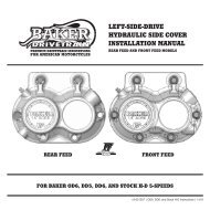
<strong>BAKER</strong> <strong>FRANKENTRANNY</strong> BUILDER’S <strong>KIT</strong>V4-39093) Install the 4 th (P/N 102-6E) gear shift fork onto the 4 th (P/N 61234C) countershaft gear. Whileholding the shift fork into position, screw back in the set screw for the auxiliary fork rod until it isflush with the side cover gasket surface, figure 15.4) Install the 3 rd (P/N 102-6F) gear counter shaft and2 nd (101-56E) gear mainshaft forks, reference figure1 and 16 for correct placement of shift forks.5) If you did not remove the 1/2-20 fork rod setscrew from the left side of the case during removalof your stock gearset due so now. Slide the providedfork rod (P/N 122-64; 6.250” rod length) through theprimary side of the transmission making sure you gothrough all shift forks; 1 st mainshaft (P/N 101-6E), 3 rdcountershaft (P/N 102-6F), and 2 nd mainshaft (P/N101-56E) forks.6) Install the 1/2-20 fork rod set screw with BlueLoctite ® ; thread into case until it bottoms out thenback off a 1/2 turn. Reinstall your transmission drainplug.7) Apply a generous amount of transmission oil tothe forks and fork rods. With all the forks installed,check to make sure that all forks slide freely on thefork rods by moving them back and forth. If youexperience any binding in the 4 th gear counter shaftfork, you need to go back and perform a clearancecheck of the auxiliary fork rod / bridge; located instep 2 of the case preparation.4C FORK3C FORK1M FORK2M FORKSHIFT FORK PLACEMENT FIGURE 16INSTALLING DRUM SHIM FIGURE 17SHIFT SYSTEM INSTALLATIONThe shift system comes with 3 shims (one .025”thick and two .020” thick), start by installing the .020”thick shim on the shifter pawl side of the drum,shown in figure 17.1) Install the shift system onto the transmission;making sure to line up the fork pins with the groovesin the shift drum.2) Install the four 1/4-20 SHCS bolts with washers;snug the bolts down evenly working in a circularpattern until all four bolts are tight.CHECKING DRUM END PLAY FIGURE 18NEVER RUN ONE CAP SCREW ALL THE WAY DOWN WITHOUTSEQENTIALLY TIGHTENING THE OTHER THREE AS SPECIFIED;IRREPARABLE DAMAGE WILL RESULT.3) Check shift drum end play by using a feeler gauge as shown in figure 18. Shift drum end playis .002” - .010”.A. Place the feeler gage in between the shift drum shim and pillow block ; holding the drumall the way toward the exhaust side. If the measurement is within the specification listedabove proceed to step 4.(CONTINUED ON NEXT PAGE)PAGE 12 - SHIFT FORK INSTALLATION / SHIFT SYSTEM