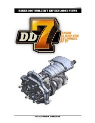
BAKER FRANKENTRANNY BUILDER'S KIT - Baker Drivetrain
BAKER FRANKENTRANNY BUILDER'S KIT - Baker Drivetrain
BAKER FRANKENTRANNY BUILDER'S KIT - Baker Drivetrain

You also want an ePaper? Increase the reach of your titles
YUMPU automatically turns print PDFs into web optimized ePapers that Google loves.
E.<strong>BAKER</strong> <strong>FRANKENTRANNY</strong> BUILDER’S <strong>KIT</strong>V4-3909IT IS CRITICAL THAT YOU DO NOTDRAG THE MAINSHAFT THREADS ORSPLINES ACROSS THE MAIN GEARSEAL; THIS WILL CAUSE DAMAGE TO THESEAL CAUSING FUTURE LEAK ISSUES.6) Using a rubber mallet tap the side of the bearingdoor (area over the dowels) on each side slowlywalking in the trap door / gearset assembly until itsflush and up against the gasket. NEVER HAMMER ONTHE BEARINGS TO FULLY SEAT THE BEARING DOOR;THIS WILL CAUSE BEARING FAILURE AND DAMAGEYOUR GEARSET.7) Install the bottom four 5/16-18 SHCS and washerswith Blue Loctite ® . Torque the four bottom bolts,starting in the center and working your way out to thesides to 16-18 ft-lbs (200-225 in-lbs).8) Install the top four 1/4-20 SHCS and washers withBlue Loctite ® . Torque the four top bolts, starting in thecenter and working your way out to the sides to 8-10ft-lbs (100-120 in-lbs).9) In your builders kit we supply a speed sensor plugwith O-ring and bolt; install the speed sensor plug onyour transmission case. Using WD40 ® on the O-Ringwill aid in installing the plug. Using Blue Loctite ® on thestock speed sensor bolt torque to 8-10 ft-lbs (100-120in-lbs).10) Install your motorcycle speed sensor on the newbearing door using the provided button head bolt withBlue Loctite ® , torque to 8-10 ft-lbs (100-120 in-lbs),figure 12.SHIFT FORK INSTALLATIONReference the included parts, figure 1 on page 4 andlegend on page 5. You will notice that the 3 rd (P/N102-6F), 2 nd (P/N 101-56E), and 1 st (P/N 101-6E) gearforks will ride on the primary fork rod (like your stock5-Speed). The 4 th (P/N 102-6E) gear fork will ride onan auxiliary fork rod connected to the bearing door.1) Using a 3/32” Allen, back out the auxiliary fork rodturning it counter clockwise, until a little over 3/4" issticking out of the bearing door (past the side covergasket surface), figure 13.2) Install the 1 st (P/N 101-6E) gear mainshaft fork.You must slide the 1 st gear away from the bearingdoor and engage the dog teeth of the adjacent gear(4 th ) to allow room for the fork to slide into positionfigure 14.SHOWING SPEED SENSOR INSTALLED FIGURE 12AUXILIARY ROD ADJUSTER FIGURE 13SHOWING 1ST GEAR ENGAGED FIGURE 14INSTALLING 4TH GEAR SHIFT FORK FIGURE 15(CONTINUED ON NEXT PAGE)PAGE 11 - GEARSET INSTALLATION / FORK INSTALLATION