BAKER FRANKENTRANNY BUILDER'S KIT - Baker Drivetrain
BAKER FRANKENTRANNY BUILDER'S KIT - Baker Drivetrain
BAKER FRANKENTRANNY BUILDER'S KIT - Baker Drivetrain

You also want an ePaper? Increase the reach of your titles
YUMPU automatically turns print PDFs into web optimized ePapers that Google loves.
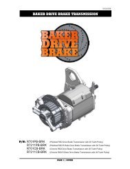
<strong>BAKER</strong> <strong>FRANKENTRANNY</strong> BUILDER’S <strong>KIT</strong>V4-3909<strong>BAKER</strong> <strong>Drivetrain</strong>’s 1999 Road King w/Part Numbers: FT106SL (Frankentranny Kit), 478-56CP-U84 (KickerCover), 3511-64 (Kick Arm/Pedal Assembly, 475-56P (Oil Spout Assembly), and 5011(Gates Ignition Kit)P/N:FT106P (<strong>FRANKENTRANNY</strong> BUILDERS <strong>KIT</strong>; 01-06 FL / 01-05 DYNA ® / 00-06 SOFTAIL ® )FT106L (<strong>FRANKENTRANNY</strong> BUILDERS <strong>KIT</strong>; 90-97 BIG TWIN MOTORCYCLES)FT106SL (<strong>FRANKENTRANNY</strong> BUILDERS <strong>KIT</strong>; 98-99 SOFTAIL ® / 98-00 FL, DYNA ® )PAGE 1 - COVER
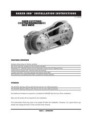
FEATURESV4-3909The Frankentranny Builders Kit effectively converts a factory 5-Speed into a 6-Speed overdrivewith provisions for a 1936-based 4-Speed kicker. Why did we do this? Because a timeless kickeron a Big Twin looks really cool! And kick starting your bike in a crowd of button pushers is bonermaterial.FITMENT<strong>BAKER</strong> <strong>FRANKENTRANNY</strong> <strong>KIT</strong> OVERVIEW• 1990-2006 Big Twin Motorcycles (except 2006 Dyna ® )TOOLS, RESOURCES, REQUIRED PARTS• Touring Models Must Use A True Dual Exhaust System For Proper Fitment• Factory Service Manual For Your Motorcycle• Factory Parts Manual For Your Motorcycle• Common Hand Tools (allens, sockets, hammer / chisel)• Die Grinder or Files (if transmission case needs to be modified)• Torque Wrench (with ft. lbs. and in. lbs.)• Blue Loctite ® (242 Removable) or Equivalent• Red Loctite ® (271 Permanent) or Equivalent• Feeler gauges• Main Drive Gear & Bearing Service Toolso <strong>BAKER</strong> P/N ToolA-56o H-D ® Equivalent P/N 35316A• Pulley Nut Socketo <strong>BAKER</strong> P/N TOOLD-56o H-D ® Equivalent P/N 94660-37B• Inner Primary Race Service Toolo <strong>BAKER</strong> P/N TOOLB-56o H-D ® Equivalent P/N 34902APARTS REQUIRED TO COMPLETE BUILD• Kicker Cover Kit w/Kicker Gears, See Page 14.• Kicker Arm w/Pedal, See Page 14.• Ignition Retrofit Required On Twin Cam Models, See Page 14.• Fuel Injected Motorcycles Must Be Converted To Carburetor.• 1993-2006 Touring Models Require A <strong>BAKER</strong> Oil Spout. The Bulky Stock Spout InterferesWith The Frankentranny Bearing Door, See Page 14.• Touring Models Must Use A True Dual Exhaust System For Proper Fitment.<strong>BAKER</strong> HIGHLY RECOMMENDS THAT OUR TRANSMISSION BUILDER’S<strong>KIT</strong>’S BE INSTALLED ONLY BY A TRAINED AND OR SEASONED MECHANICWITH PRIOR H-D ® TRANSMISSION EXPERIENCE. IF YOU HAVE NEVERSERVICED AN H-D ® TRANSMISSION; DO NOT ATTEMPT INSTALLING THISBUILDERS <strong>KIT</strong>.PAGE 2 - OVERVIEW
<strong>BAKER</strong> <strong>FRANKENTRANNY</strong> BUILDER’S <strong>KIT</strong>V4-3909TABLE OF CONTENTS:2) Overview3) Table Of Contents4) Included Parts Breakdown5) Included Parts Breakdown Legend6) Included Parts Breakdown w/Legend7) Included Parts Breakdown w/Legend8) Disassembly, Case Preparation9) Case Preparation Continued10) Case Preparation Continued, Gearset Installation11) Gearsest Installation Continued, Shift Fork Installation12) Shift Fork Installation Continued, Shift System Installation13) Shift System Installation Continued, Finish Line14) Notes15) Terms16) DisclaimerPAGE 3 - TABLE OF CONTENTS
<strong>BAKER</strong> <strong>FRANKENTRANNY</strong> EXPLODED VIEWINCLUDED PARTS DETAILV4-3909FIGURE 1PAGE 4 - INCLUDED PARTS DETAIL LEGEND
<strong>BAKER</strong> <strong>FRANKENTRANNY</strong> EXPLODED VIEWINCLUDED PARTS DETAIL LEGENDV4-3909ITEM QTY P/N DESCRIPTION1 1 10705-01149 C-Clip, Actuator Rod2 2 TWC411 Ground Washer, Actuator Rod3 1 TC411 Thrust Washer, Actuator Rod4 1 125-5R Actuator Rod5 1 6N4-SIDE Gasket, Side Cover6 1 35652-79B Gasket, Bearing Door7 4 33001 Washer, Shift System8 4 23207 1/4-20 x 1.250” SHCS9 1 4-6QEN / 5-6 QSN / 5-6 QLN Shift System10 2 98-620GA .020” Shim, Shift System11 1 98-625GA .025” Shim, Shift System12 1 34904-86E Gasket, Top Cover13 1 37088-90E Rod, Clutch Release14 1 73753 1/4-20 x .625” BHCS15 1 108-6EP Speedo Plug16 1 66808 O-Ring, Buna #01417 4 6099SS Washer, 1/4”18 4 25C125KCSS/P 1/4-20 x 1.250” SHCS S.S.P.19 4 6100 Washer, 5/16”20 4 31C150KCSS/P 5/16-18 x 1.500” SHCS S.S.P.21 1 See Figure 2 Door / Gearset Assembly22 1 102-6E 4 th Gear Countershaft Fork23 1 101-6E 1 st Gear Mainshaft Fork24 1 102-6F 3 rd Gear Countershaft Fork25 1 101-56E 2 nd Gear Mainshaft Fork26 1 122-64 Fork Rod (6.250” Length)27 1 25702 1/2-20 X .500” Fork Rod Plug28 1 6209 Bearing, Main Drive Gear29 1 1302-334PP Beveled Snap Ring30 1 12067B Seal, Main Drive Gear31 1 11165A Quad Seal32 1 33344-94S Spacer, Pulley33 1 34091-85 Inner Bearing RacePAGE 5 - INCLUDED PARTS DETAIL LEGEND
V4-3909<strong>BAKER</strong> <strong>FRANKENTRANNY</strong> EXPLODED VIEWINCLUDED PARTS DETAILFIGURE 2ITEM QTY P/N DESCRIPTION1 1 168-6N4 Nut, Mainshaft2 1 WHM-200 2” Internal Spiral Lock3 1 1640-DSTN Bearing, Mainshaft4 1 37141 3/4-16 Nylock Nut5 2 24040 10-32 x 1.500” BHCS6 1 51740-001 3/8-24 Zero Leak Drain Plug7 1 204KG Bearing, Countershaft8 1 2-6F-P Bearing Door9 1 25287 10-32 x 2.000” Set Screw10 1 112-6D Auxiliary Fork Rod11 1 115-6E Support Bridge12 1 TRB-1423 Shim, Mainshaft13 1 See Figure 3 Gearset Assembly14 2 HK2520 Bearing, Main Drive Gear15 1 61005M Main Drive Gear16 1 12035B Seal, Main Drive GearPAGE 6 - INCLUDED PARTS DETAIL
V4-3909<strong>BAKER</strong> <strong>FRANKENTRANNY</strong> EXPLODED VIEWINCLUDED PARTS DETAILFIGURE 3ITEM QTY P/N DESCRIPTION1 5 8876A Bearing, Gearset2 1 ` 60866M 6 th Gear, Mainshaft3 7 6003B Thrust Washer, Gearset4 6 11067A Retaining Ring, Gearset5 1 62941M 1 st Gear, Mainshaft6 1 61234M 4 th Gear, Mainshaft7 2 603M2C 3 rd Gear Mainshaft / 2 nd Gear Countershaft8 1 62212M 2 nd Gear, Mainshaft9 1 996041-8 Mainshaft, Kicker Style10 1 60866C Countershaft, 6 th Gear11 1 61005C 5 th Gear, Countershaft12 1 61573C 3 rd Gear, Countershaft13 1 61234C 4 th Gear, Countershaft14 1 62941C 1 st Gear, CountershaftPAGE 7 - INCLUDED PARTS DETAIL
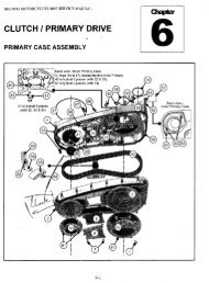
<strong>BAKER</strong> <strong>FRANKENTRANNY</strong> BUILDER’S <strong>KIT</strong>DISSASSEMBLYV4-39091) FOR YOUR SAFETY, DISCONNECT BOTH BATTERY CABLES (FAILURE TO DUE SOCOULD RESULT IN PERSONAL INJURY).2) With your bike securely supported on a bike lift or jack, drain the transmission fluid. Refer toyour Factory Service Manual for location of your drain plug.3) Refer to your Factory Service Manual for transmission gearset, main drive gear, and maindrive gear bearing removal.4) Remove your transmission speed sensor from the transmission case.CASE PREPERATIONThe <strong>BAKER</strong> FrankenTranny Builder Kit hardware is designed to fit in a stock H-D ® andaftermarket transmission cases without modification to the case or Six-Speed components, butthere are exceptions. The internal walls of transmission cases float around occasionally, this isnot a quality problem, but rather is inherent in the casting process. With that in mind the followingsteps are a number of checks to make sure that your new builders kit will function and performflawlessly.IT IS CRITICAL THAT BEFORE YOU DO ANY MODIFICATION TO YOURTRANSMISSION CASE THAT YOU THROUGHLY CLEAN OUT THE CASEWITH BRAKE CLEANER OR LACQUER THINNER IN A WELL VENTILATEDAREA, DRY OUT, THEN TAPE OFF THE COUNTER SHAFT BEARING WITH DUCTTAPE TO PREVENT ANY DEBRIS FROM ENTERING THE BEARING AS YOU WILLNOT BE REPLACING IT. IF YOU NOTICE THAT THE BEARING IS DAMAGED INANYWAY PLEASE REFER TO YOUR FACTORY SERVICE MANUAL FOR REPLACINGTHE BEARING. COUNTER SHAFT BEARING H-D ® P/N 8977 OR <strong>BAKER</strong> P/NBK2526.1) Checking for 6 th gear (P/N: 60866M) Mainshaft clearance.A. Place the provided door gasket onto the transmission case. The gasket is going to actlike a template.B. If the meat of the boss around the 5/16-18screw hole and fork rod boss hole is above orbelow the profile of the door gasket. Mark thearea with a black marker; from roughly the 10o’clock to 2 o’clock position on the 5/16-18screw hole boss and the 6 o’clock to 8 o’clockposition on the fork rod boss, shown in figure4. If the meat of the boss is below or the sameas the profile of the door gasket proceed tostep 2.C. After marking the area of concern in step 1B,remove the door gasket, then remove thecase material using a coarse flat file or die SHOWN IN RED ARE THE AREAS OF CONCERN FIGURE 4grinder. Remove only the marked materialroughly a ½” back from the door gasket surface.(CONTINUED ON NEXT PAGE)PAGE 8 - DISSASSEMBLY / CASE PREP
<strong>BAKER</strong> <strong>FRANKENTRANNY</strong> BUILDER’S <strong>KIT</strong>V4-39092) Checking for Auxiliary Fork Rod bridge clearance.A. The auxiliary fork rod bridge comes installed onthe inside of the bearing door shown in figure 5.The bridge functions as the support for the 4 thgear counter shaft fork.B. Using the door gasket as a template again, as instep 1A. If any transmission case material isbelow the profile of the door gasket, mark with ablack marker see figure 6.C. If case material is not below the gasket profileproceed to step 3. Remove the marked materialwith a coarse round file or die grinder. Removethe material inward (perpendicular to gasketsurface) roughly 1-3/8” from the gasketsurface.3) Checking right side pillow block clearance.A. Install the shift system on the transmissioncase. Install the four 1/4-20 SHCS bolts withwashers; snug the bolts down evenly workingin a circular pattern until all four bolts are tight.NEVER RUN ONE CAP SCREW ALL THEWAY DOWN WITHOUT SEQENTIALLYTIGHTENING THEOTHER THREE AS SPECIFIED; IRREPARABLEDAMAGE WILL RESULT.B. Any clearance greater than zero is acceptable,figure 7.C. If you are installing this builder’s kit into aDelkron ® Softail ® case, install the shift systemonto the case and mark where the right sidepillow block hits. You will have to remove somematerial as shown in figure 8 using a coarse fileor die grinder.SHOWING AUXILIARY FORK ROD FIGURE 5SHOWN IN RED IS AREA OF CONCERN FIGURE 64) Checking top cover fitment.CLEARANCE BETWEEN PILLOW BLOCK AND CASE FIGURE 7A. If you are installing an aftermarket topcover, you will have to check for proper fitmentaround the shift system. Some grinding on thecasting webs might be necessary for correctfunction of the shift drum. All checks should beREMOVE MATERIALmade with the shift system installed on theYOU MARKED IN STEPtransmission.3CIF YOU HAVE A 2000-2006 SOFTAIL ® , 2001-2005 DYNA ® , OR A 2001-2006 FLT / FLHYOU MUST MODIFIY YOUR STOCK SHIFTERPAWL (RATCHET PAWL). AS SHOWN ON THENEXT PAGE.(CONTINUED ON NEXT PAGE)SHOWN IS THE AREA OF CONCERN FIGURE 8PAGE 9 - CASE PREP
<strong>BAKER</strong> <strong>FRANKENTRANNY</strong> BUILDER’S <strong>KIT</strong>V4-39095) Shifter Pawl modification.A. Proceed to gearset installation if the year andmodel specified on page 9 does not match yourmotorcycle.B. Following the procedures in your FactoryService Manual, remove the ratchet pawl fromthe transmission case.C. Remove the spring-loaded pawl from the arm togain clear access to the “beak” on the arm.Using figures 9-10, remove the material asshown with a bench grinder or D.A. Grinder.D. Reassemble the ratchet pawl per yourFactory Service Manual into thetransmission case.FIGURE 9 FIGURE 10FIGURES SHOWING BEFORE AND AFTER PAWL MODIFICATIONGEARSET INSTALLATIONIT IS CRITICAL THAT THE TRANSMISSION CASE BE FREE OF DEBRIS ANDDIRT. USING BRAKE CLEANER OR LACQUER THINNER IN A WELLVENTILATED AREA, CLEAN OUT THE TRANSMISSION CASE. ANY DEBRISLEFT IN CASE MIGHT CAUSE SEVERE DAMAGE TO THE GEARSET AND / ORBEARINGS.1) Install the provided main bearing (P/N: 6209) into the case with snap ring (P/N: 1302-334PP),bevel side facing out. Refer to your Factory Service Manual for guidelines and proper toolsrequired.SPECIAL NOTE – 2000-UP 88B SOFTAIL ® TRANSMISSION CASES HAVE ANOTED DEFECT TO THE LANDINGTHAT SUPPORTS THE 8996A (MAINBEARING). THIS LANDING COMES STRAIGHTFROM THE FACTORY WITH A VERY THINWALL THICKNESS AND CRACKS IN THECORNER BETWEEN THE LANDING AND THE8996A BEARING BORE. INSPECTCAREFULLY FOR THIS SITUATION, FIGURE11. WHEN INSTALLING THE NEW BEARING,PRESS IT IN CAREFULLY AND DO NOTARROW POINTING TO THE AREA OF CONCERNCRACK THE LANDING OFF OF THE CASE.FIGURE 112) Remove the 5 th main gear (P/N: 61005M) from the mainshaft on your new gearset by sliding itoff the end.3) Install the 5 th main gear into the transmission case referencing your Factory Service Manual forguidelines and proper installation tools.4) Install the bearing door gasket (P/N: 35652-79B) onto the transmission, making sure thegasket is fully seated on the dowels and is against the case gasket surface.5) Apply some WD40 ® or equivalent to the main drive gear seal and the mainshaft on the gearsetassembly. Install the gearset by sliding the mainshaft through the main drive gear and slowlypushing the whole trap door / gearset assembly until the case dowels pins contact the dowelholes in the bearing door.(CONTINUED ON NEXT PAGE)PAGE 10 - CASE PREP / GEARSET INSTALLATION
E.<strong>BAKER</strong> <strong>FRANKENTRANNY</strong> BUILDER’S <strong>KIT</strong>V4-3909IT IS CRITICAL THAT YOU DO NOTDRAG THE MAINSHAFT THREADS ORSPLINES ACROSS THE MAIN GEARSEAL; THIS WILL CAUSE DAMAGE TO THESEAL CAUSING FUTURE LEAK ISSUES.6) Using a rubber mallet tap the side of the bearingdoor (area over the dowels) on each side slowlywalking in the trap door / gearset assembly until itsflush and up against the gasket. NEVER HAMMER ONTHE BEARINGS TO FULLY SEAT THE BEARING DOOR;THIS WILL CAUSE BEARING FAILURE AND DAMAGEYOUR GEARSET.7) Install the bottom four 5/16-18 SHCS and washerswith Blue Loctite ® . Torque the four bottom bolts,starting in the center and working your way out to thesides to 16-18 ft-lbs (200-225 in-lbs).8) Install the top four 1/4-20 SHCS and washers withBlue Loctite ® . Torque the four top bolts, starting in thecenter and working your way out to the sides to 8-10ft-lbs (100-120 in-lbs).9) In your builders kit we supply a speed sensor plugwith O-ring and bolt; install the speed sensor plug onyour transmission case. Using WD40 ® on the O-Ringwill aid in installing the plug. Using Blue Loctite ® on thestock speed sensor bolt torque to 8-10 ft-lbs (100-120in-lbs).10) Install your motorcycle speed sensor on the newbearing door using the provided button head bolt withBlue Loctite ® , torque to 8-10 ft-lbs (100-120 in-lbs),figure 12.SHIFT FORK INSTALLATIONReference the included parts, figure 1 on page 4 andlegend on page 5. You will notice that the 3 rd (P/N102-6F), 2 nd (P/N 101-56E), and 1 st (P/N 101-6E) gearforks will ride on the primary fork rod (like your stock5-Speed). The 4 th (P/N 102-6E) gear fork will ride onan auxiliary fork rod connected to the bearing door.1) Using a 3/32” Allen, back out the auxiliary fork rodturning it counter clockwise, until a little over 3/4" issticking out of the bearing door (past the side covergasket surface), figure 13.2) Install the 1 st (P/N 101-6E) gear mainshaft fork.You must slide the 1 st gear away from the bearingdoor and engage the dog teeth of the adjacent gear(4 th ) to allow room for the fork to slide into positionfigure 14.SHOWING SPEED SENSOR INSTALLED FIGURE 12AUXILIARY ROD ADJUSTER FIGURE 13SHOWING 1ST GEAR ENGAGED FIGURE 14INSTALLING 4TH GEAR SHIFT FORK FIGURE 15(CONTINUED ON NEXT PAGE)PAGE 11 - GEARSET INSTALLATION / FORK INSTALLATION
<strong>BAKER</strong> <strong>FRANKENTRANNY</strong> BUILDER’S <strong>KIT</strong>V4-39093) Install the 4 th (P/N 102-6E) gear shift fork onto the 4 th (P/N 61234C) countershaft gear. Whileholding the shift fork into position, screw back in the set screw for the auxiliary fork rod until it isflush with the side cover gasket surface, figure 15.4) Install the 3 rd (P/N 102-6F) gear counter shaft and2 nd (101-56E) gear mainshaft forks, reference figure1 and 16 for correct placement of shift forks.5) If you did not remove the 1/2-20 fork rod setscrew from the left side of the case during removalof your stock gearset due so now. Slide the providedfork rod (P/N 122-64; 6.250” rod length) through theprimary side of the transmission making sure you gothrough all shift forks; 1 st mainshaft (P/N 101-6E), 3 rdcountershaft (P/N 102-6F), and 2 nd mainshaft (P/N101-56E) forks.6) Install the 1/2-20 fork rod set screw with BlueLoctite ® ; thread into case until it bottoms out thenback off a 1/2 turn. Reinstall your transmission drainplug.7) Apply a generous amount of transmission oil tothe forks and fork rods. With all the forks installed,check to make sure that all forks slide freely on thefork rods by moving them back and forth. If youexperience any binding in the 4 th gear counter shaftfork, you need to go back and perform a clearancecheck of the auxiliary fork rod / bridge; located instep 2 of the case preparation.4C FORK3C FORK1M FORK2M FORKSHIFT FORK PLACEMENT FIGURE 16INSTALLING DRUM SHIM FIGURE 17SHIFT SYSTEM INSTALLATIONThe shift system comes with 3 shims (one .025”thick and two .020” thick), start by installing the .020”thick shim on the shifter pawl side of the drum,shown in figure 17.1) Install the shift system onto the transmission;making sure to line up the fork pins with the groovesin the shift drum.2) Install the four 1/4-20 SHCS bolts with washers;snug the bolts down evenly working in a circularpattern until all four bolts are tight.CHECKING DRUM END PLAY FIGURE 18NEVER RUN ONE CAP SCREW ALL THE WAY DOWN WITHOUTSEQENTIALLY TIGHTENING THE OTHER THREE AS SPECIFIED;IRREPARABLE DAMAGE WILL RESULT.3) Check shift drum end play by using a feeler gauge as shown in figure 18. Shift drum end playis .002” - .010”.A. Place the feeler gage in between the shift drum shim and pillow block ; holding the drumall the way toward the exhaust side. If the measurement is within the specification listedabove proceed to step 4.(CONTINUED ON NEXT PAGE)PAGE 12 - SHIFT FORK INSTALLATION / SHIFT SYSTEM
<strong>BAKER</strong> <strong>FRANKENTRANNY</strong> BUILDER’S <strong>KIT</strong>V4-3909B. If the measurement is greater then .010” remove the shift system and add one of theother shims and reinstall the shift system as specified in step 2. Re-measure the drumend play until the measurement is within the specification listed (.002”-.010”).C. In the unlikely event that the drum end play is less than the lower limit of .002”; whichcould be due to variation in your transmission housing or stack up of the <strong>BAKER</strong>components, give us a call toll free @ 1-877-640-2004. Please have a set of verniercalipers available to take measurements during your conversation to assist us withdiagnosis over the phone. If we determine that the issue lies with your transmissioncase, we will assist you on how to remedy the problem. If the issue lies with our <strong>BAKER</strong>components we will ship overnight the replacement hardware necessary to remedy theproblem.4) Now that the shift drum end play is set; removethe four bolts and apply Blue Loctite ® re-install boltswith washers. Snug down as specified in step 2 andthen torque to 8-10 ft-lbs (100-120 in-lbs).5) Set the shifter pawl adjustment per your FactoryService Manual found in section 7 under, ShifterLinkage Adjustment. Adjustment should be made in3 rd gear; measurement must be equal to within .010”between pins, see figure 19. Shift through all gearswhile spinning the mainshaft to make sureeverything is functioning correctly.6) Install the top cover gasket and top cover withbolts referring to your Factory Service Manual.FINISH LINE1) Install the supplied inner bearing race onto the mainshaft, P/N 34091-85 following your FactoryService Manual and using the Inner Primary Race Service Tool <strong>BAKER</strong> P/N TOOLB-56 or H-D ®Equivalent P/N 34902A. An optional <strong>BAKER</strong> High Torque Bearing Kit is available P/N 189-56.The <strong>BAKER</strong> High Torque Bearing Kit replaces the factory roller bearing and race with a precisionhoned ball bearing and seal. This will eliminate the possibility of the race moving and potentiallycausing leaks or damage to the transmission.2) Install the provided clutch release and actuator rod into the mainshaft.SHIFTER PAWL PIN ADJUSTMENT FIGURE 193) Re-install all primary components, rear belt, sprocket or pulley; that you removed todisassemble the transmission following your Factory Service Manual.4) Install the kicker cover of your choice, and it’s components per the manufacturer’s instructionsheets.5) Install your exhaust and double check that all fasteners are tight on the motorcycle and anyancillary parts that you removed to perform this installation are back in their intended place on themotorcycle.6) Fill the transmission with fluid. The <strong>BAKER</strong> Frankentranny Builders Kit comes with its own 23fl-oz bottle of Heavy Duty Platinum Spectro ® Transmission Fluid.Once the maiden voyage had been made around the block or down the road. Take the time todouble check all fasteners and hydraulic fittings for tightness. Also with the bike as close to levelas you can safely get it and the transmission fluid warmed up, double check the level of the fluid.Drain off any excess fluid if the transmission is overly full. Level should be at the bottom of thehole. Re-install the oil level plug with; snug. You are complete….PAGE 13 - SHIFT SYSTEM / FINISH LINE
V4-3909<strong>BAKER</strong> OFFERS THE FOLLOWING ANCILLARY PRODUCTS FOR THE <strong>FRANKENTRANNY</strong>BUILDER’S <strong>KIT</strong>:P/N478-56HP-U84478-56CP-U84479-56P-U84<strong>BAKER</strong> <strong>FRANKENTRANNY</strong> BUILDER’S <strong>KIT</strong>DESCRIPTIONKicker cover with polished finish, hydraulic type including Klassic KickerGears & 1.5” piston. Requires an H-D master cylinder or applicableaftermarket unit with 11/16” piston diameter. Hydraulic clutch actuation isthe aesthetically cleanest setup because hydraulic line can be easilyhidden.Kicker cover with polished finish, cable type including Klassic KickerGears and actuator ball ramps. As shown on front of these instructions.Compatible with 1990-2006 stock clutch cables and is the easiest toinstall and most economical clutch actuation setup.Function Formed Hydraulic Kicker Cover with polished finish, includingKlassic Kicker Gears & 1.5” Piston. Requires an H-D master cylinder orapplicable aftermarket unit with 11/16” piston diameter. Hydraulic clutchactuation is the aesthetically cleanest setup because hydraulic line canbe easily hidden.3510-64P Kick arm assembly, straight design, polished stainless steel, with bronzepedal3511-64P Kick arm assembly, straight design, +1” length, polished stainless steel,w/ bronze pedal474-56C-EOil spout assembly, FF type, chrome, 1993-99 FL474-56P-EOil spout assembly, FF type, polished, 1993-99 FL474-56C-TOil spout assembly, FF type, chrome, 2000-01 FL474-56P-TOil spout assembly, FF type, polished, 2000-01 FL475-56C Oil spout assembly, FF type, chrome, 2002-06 FL, includes polishedstainless steel breather line475-56P Oil spout assembly, FF type, polished, 2002-06 FL, includes polishedstainless steel breather lineFOR TWIN CAM MODELS, ONE OF THE FOLLOWING IGNITION RETROFIT CHOICES ISREQUIRED FOR FUNCTIONAL KICKER OPERATION.P/NDESCRIPTIONT5Morris Magneto nose cone assembly, polished. Fits 1999-2006 TC88A& 2000-06 TC88B* Specify gear or chain cam drive system when ordering to get thecorrect worm drive gearset.3757 Vulcan Ignition conversion kit for chain cams, chrome. Fits 1999-05Dyna, 1999-06 FL & Softail3886 Vulcan Ignition conversion kit for gear cams, chrome. Fits 1999-05 Dyna,1999-06 FL & Softail4365 Vulcan Ignition conversion kit for chain cams, chrome. Fits 2006-upDyna, 2007-up FL & Softail* Includes ignition module.5011 Gates Ignition conversion kit, polished. Fits 1999-05 Dyna, 1999-06 FL &Softail* Specify gear or chain cam drive system when ordering; does notinclude ignition module but utilizes any EVO era nose cone mountedmodule.PAGE 14 – PARTS REQUIRED TO COMPLETE YOUR BUILD
V4-3909<strong>BAKER</strong> <strong>BAKER</strong> <strong>FRANKENTRANNY</strong> BILLET KICKER BUILDER’S COVER <strong>KIT</strong>SPECIAL ORDERSA minimum $500 deposit is required with all special orders. Special orders include unique case finishes, unique side doorrequests (i.e.; wrinkle black door or no logo).ALL OTHER ORDERSOrders can be pre-paid using VISA, MasterCard or American Express.Prices shown are F.O.B. Haslett, MI. <strong>BAKER</strong> provides free UPS ground shipping on all retail orders for completetransmissions or transmission kit. UPS air shipment is available upon request. Customer is responsible for air shipmentpremiums.LIMITED WARRANTY<strong>BAKER</strong> Inc. transmission assemblies, transmission kits, and wide tire kits are guaranteed to the original purchaser to befree of manufacturing defects in materials and workmanship for a period of 5 years from the date of purchase or up to50,000 miles - whichever is sooner.If the product is found by <strong>BAKER</strong> to be defective, such products will, at the option of <strong>BAKER</strong>, be replaced or repairedat cost to <strong>BAKER</strong>.In the event warranty service is required, the original purchaser must call or write <strong>BAKER</strong> immediately with the problem.If it is deemed necessary for <strong>BAKER</strong> to make an evaluation to determine whether the transmission assembly ortransmission kit is defective, the entire transmission assembly, whether originally purchased as an assembly or kit, mustbe properly packaged and returned prepaid to <strong>BAKER</strong> with a copy of the original invoice of purchase.If after an evaluation has been made by <strong>BAKER</strong> and a defect in materials and/or workmanship is found, <strong>BAKER</strong> will,at <strong>BAKER</strong> option, repair or replace the defective part of the assembly.Warranty card must be returned within 45 days of purchase to be valid.ADDITIONAL WARRANTY PROVISIONSThis limited warranty does not cover labor or other costs or expenses incidental to the repair and or replacement of<strong>BAKER</strong> products. This warranty does not apply if one or more of the following situations is judged by <strong>BAKER</strong> to berelevant: improper installation, accident, modification (including but not limited to use of unauthorized parts), racing, highperformance application, mishandling, misapplication, neglect (including but not limited to improper maintenance), orimproper repair.<strong>BAKER</strong> shall not be liable for any consequential or incidental damages arising out of or in connection with a <strong>BAKER</strong>transmission assembly, transmission kit, swingarm, fender, component or part. Consequential damages shall includewithout limitation, loss of use, income or profit, or losses sustained as the result of injury (including death) to any person orloss of or damage to property.<strong>BAKER</strong> transmissions, transmission kits, and Wide Tire Kits are designed exclusively for use in Harley-Davidson®motorcycles. <strong>BAKER</strong> shall have no warranty or liability obligation if a <strong>BAKER</strong> part is used in any other application.If it is determined that a <strong>BAKER</strong> transmission assembly has been disassembled during the warranty period for anyreason, this limited warranty will no longer apply.PAGE 15 - TERMS
V4-3909<strong>BAKER</strong> <strong>FRANKENTRANNY</strong> BUILDER’S <strong>KIT</strong>The words Harley and H-D are registered trademarks and are for reference only. Use of H-D model designations and partnumbers are for reference only. <strong>BAKER</strong> <strong>Drivetrain</strong> has no association with, and makes no claim against, these words,trademarks, or companies.It is the sole responsibility of the user to determine the suitability of this product for his or her use, and the user shallassume all legal, personal injury risk and liability and all other as well as all other obligations, duties and risks associatedtherewith.CUSTOMER SUPPORTFor any installation or service questions, please contact our <strong>BAKER</strong> technical department toll free: 1-877-640-2004.PAGE 16 - DISCLAIMER