

(LRM) Line Replaceable Module - Amphenol Aerospace
(LRM) Line Replaceable Module - Amphenol Aerospace
(LRM) Line Replaceable Module - Amphenol Aerospace
- No tags were found...

You also want an ePaper? Increase the reach of your titles
YUMPU automatically turns print PDFs into web optimized ePapers that Google loves.
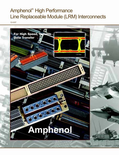
®<strong>Amphenol</strong> High Performance<strong>Line</strong> <strong>Replaceable</strong> <strong>Module</strong> (<strong>LRM</strong>) Interconnects12-037For High Speed, ReliableData Transfer1.25 Gbps<strong>Amphenol</strong>
<strong>Amphenol</strong> solves board mount connector requirements byoffering their <strong>LRM</strong> <strong>Line</strong> <strong>Replaceable</strong> <strong>Module</strong> Interconnectswith the widest design flexibility - combinations of moduleand backplane inserts - thousands of combinationsare possible, tailored to meet customer needs.<strong>LRM</strong> interconnects can bedesigned in One Bay ... Two Bay ...Three Bay ... or more configurations withmany shell designs available.The B 3 Brush contact is the standardcontact for the <strong>LRM</strong> due to its low mating force, stableelectrical performance and extended service life.Standard “symmetrical” arrangements consist ofcontact counts of: 80 ... or 108 ... or 152 ... or 180within each insert.Staggered grid patterns, or more compact GEN-Xpatterns, are used to fill the insert cavities with brushcontacts. A multitude of <strong>LRM</strong> designs are possible withthe use of other configurations of brush contact inserts.Design flexibility is expanded even more with the ability toadd combinations of other types of contacts: power, high speed coax,triax, differential twinax, and quadrax contacts, fiber optic MT ferrules,high speed differential pairs, or high power RADSOK ® sockets. Flexcircuit terminations are also available.<strong>Amphenol</strong> provides the high level of design versatility that engineersneed for board level interconnects in avionics. High speed integratedcircuitry with increased contact density demands this flexibility. <strong>Amphenol</strong>lives up to its reputation for leading in innovative solutions.
line replaceable module interconnects<strong>Amphenol</strong> <strong>LRM</strong> Interconnect Solutions<strong>Amphenol</strong> ® <strong>LRM</strong> Surface Mount Connectorsmeet the high density needs of today’s integratedelectronic modules.<strong>Amphenol</strong> goes beyond the usual board levelproduct offering: and that is what you wouldexpect from a worldwide interconnect productleader. Design versatility and product reliabilitymakes <strong>Amphenol</strong> the premier choice for thesystem designer in solving boardinterconnect requirements.Flex terminationRADSOK ®high amperagecontactsSix bayconnector shellPartially populated brush contactbay to facilitate high voltagetransmission.<strong>Amphenol</strong> RuggedizedVME64x Connectors<strong>Amphenol</strong> has designed a ruggedized VME64xconnector that surpasses the standard VME64x.Metal shells, ESD protection and a robust contactsystem makes this a superior choice for harshenvironments requiring Level 2 (Flight <strong>Line</strong>)maintenance.<strong>Amphenol</strong> offers an adapter(shown below) that will easilymount the <strong>Amphenol</strong> RuggedizedVME64x connector to a standardCOTS VME64x.<strong>Amphenol</strong> RuggedizedVME64x
<strong>Module</strong> and Backplane Connectors withPower and Brush Contacts, High Speed ShieldedContacts, Fiber Optics and Flex Circuitry.Plus Ruggedized VME64x Interconnects.High speed differentialpair brush contacts2 inserts withstandard brush contactsStandard brush contacts in adifferential pair insertFiber optic MT ferrules<strong>Amphenol</strong> BackplaneCapabilities<strong>Amphenol</strong> Backplanes incorporate a widerange of interconnects. <strong>LRM</strong> surfacemount connectors with brush contacts orcombinations of brush, coax, and fiberoptics can be integrated into abackplane, SEM-E and customform factors are available.For further information, contact <strong>Amphenol</strong> <strong>Aerospace</strong>by phone: 800-678-0141 or 607-563-5011;by fax: 607-563-5157.or visit our website: www.amphenol-aerospace.com
®<strong>Amphenol</strong> <strong>Line</strong> <strong>Replaceable</strong> <strong>Module</strong> (<strong>LRM</strong>)InterconnectsModular Avionics ArchitecturalPossibilities and Advantagesoffered by <strong>Amphenol</strong> <strong>Aerospace</strong>:• <strong>LRM</strong> Surface Mount Connectors featuring the <strong>Amphenol</strong>Bristle ® Brush ® contact technology.Staggered Grid <strong>LRM</strong>GEN-X <strong>LRM</strong>Multiple strands of high tensile strength wire bundled togetherto form brush-like contacts provides low mating force,extended service life and stable electrical performance.• <strong>Amphenol</strong>’s <strong>LRM</strong> connector family offers the versatility tofacilitate custom combinations of digital, fiber optics, RF,power and special high speed inserts to meet individualcustomer requirements.• Staggered Grid TABLE <strong>LRM</strong> OF CONTENTS• Staggered grid Airflow-thru <strong>LRM</strong> - allow for widerboard packages and airflow cooling• GEN-X <strong>LRM</strong> - for extreme densities of brush contacts• Ruggedized VME64x InterconnectsTable of ContentsRuggedized VME64x<strong>Amphenol</strong> <strong>Line</strong> <strong>Replaceable</strong> <strong>Module</strong> Interconnects - Design Flexibility ......................................................................Inside CoverTable of Contents, Introduction ..................................................................................................................................................... 1<strong>LRM</strong> Surface Mount Connectors Features and Benefits; Bristle Brush Contact Advantages and Superiority .......................... 2, 3<strong>Amphenol</strong> <strong>LRM</strong> Product Evolution, Selection Criteria for F-16 and F-22 .................................................................................. 4, 5<strong>Amphenol</strong> ‘s Design Engineering and Manufacturing Expertise ............................................................................................... 6, 7<strong>LRM</strong> <strong>Module</strong> and Backplane General Information/Diagrams .................................................................................................... 8, 9Staggered Grid and Staggered Grid Airflow-thru <strong>LRM</strong> Contact Patterns .................................................................................... 10Comparison - Staggered Grid <strong>LRM</strong> vs. Staggered Grid Airflow-thru <strong>LRM</strong> .................................................................................. 11Staggered Grid <strong>LRM</strong> Typical Arrangements ......................................................................................................................... 12, 13Staggered Grid <strong>LRM</strong> Termination Options .................................................................................................................................. 14Staggered Grid <strong>LRM</strong> Typical Performance, Materials ................................................................................................................. 15Comparison - Staggered Grid <strong>LRM</strong> vs. GEN-X <strong>LRM</strong> ............................................................................................................ 16, 17GEN-X <strong>LRM</strong> Contact Pattern ...................................................................................................................................................... 18GEN-X <strong>LRM</strong> Typical Arrangements ............................................................................................................................................ 19<strong>LRM</strong> Interconnect Options - Fiber Optics, Other Contact Options, Flex Circuitry .................................................................. 20-23Electrostatic Discharge (ESD) Protection for <strong>Line</strong> <strong>Replaceable</strong> <strong>Module</strong>s ................................................................................... 24<strong>LRM</strong> Accessories and Tools ................................................................................................................................................. 25, 26Ruggedized VME64x Interconnects: Features, Benefits and Compatibility with COTS VME64x .............................................. 27VME64x Adapters, VME P0/J0 Fiber Optic Interconnects .......................................................................................................... 28Other <strong>Amphenol</strong> Board Level Interconnects - Low Mating Force Brush Connectors, Rack & Panel Connectors with Brush,SIM <strong>Module</strong>s, Termination Blocks, Wiring Interfaces, Backplane Assemblies, UHD and NAFI Connectors ................. 29-33Other <strong>Amphenol</strong> Interconnects for Board Attachment - Cylindrical Connectors with PC Tails and Compliant Pin Contacts ...... 34Aid in selection and ordering of <strong>LRM</strong> and LRU Interconnects from <strong>Amphenol</strong> ........................................................................... 35<strong>Amphenol</strong> Sales Offices and Distributor Listing11
<strong>LRM</strong> Surface Mount Connectorsfeaturing the B 3 Bristle ® Brush ® contactThe <strong>LRM</strong> connector series are high performance, high density interconnects,specifically designed to connect printed circuit boards. The<strong>Amphenol</strong> Brush or B 3 contact technology is the foundation of the <strong>LRM</strong>connector series.Features, benefits and options of <strong>LRM</strong> connectors with B 3 brushcontacts include:• GEN-X contact pattern - has .075 inch spacing along the row with .060inch between rows, offset .0375 inch between rows on the mating face.• Staggered grid contact pattern - has .100 inch spacing along the rowwith .050 inch between rows, offset .050 inch between rows on themating face• Staggered grid Airflow-thru contact pattern - for wider or oversizedboard packages between 0.235 and 0.425 inches. Wider spacing incenter also provides for more airflow cooling of the connector inserts.• Backplane design versatility:• Available with through-hole solder posts or with compliant pins forsolderless applications• Compliant/solderless backplane contacts are front replacable• ESD Protection - Staggered grid and GEN-X <strong>LRM</strong> connectors aretypically provided with ESD (Electrostatic Discharge) protection. Theyutilize the Faraday Cage principal to shunt electrostatic dischargeevents to the conductive enclosure on which the connector is mounted,thus never allowing the high voltage, high current discharge event toreside on any contacts. See page 20 for more information on ESDprotection.• Wide range of PCB/heat sink accomodations with standard surfacemount tails or optional flex-circuit termination• Polarization keys - up to 4096 possible keying positions• Vibration: Superior intermittancy-free performance under vibration• Dielectric withstanding voltage: Staggered grid and GEN-X styles:100 volts at sea level (due to the incorporation of ESD shield)• Temperature range:• Suitable for vapor phase soldering• Normal operating temperature is –65°C to +125°C• Current rating: 3.0A derated to 1.5A typical (dependant on loading)• Brush contact provides low mating and unmating forces:• 1.5 oz. per contact (typical)• 70% to 90% lower than conventional pin and socket contacts• Brush contact provides superior electrical characteristics:• Redundant current paths• Minimized constrictive resistance• Uniform current densities• Stable time/life contact resistance• Gas tight and electrical contact site integrity• Brush contact proven durability: 20,000 cycles of matingand unmating<strong>Amphenol</strong> offers configurations of <strong>LRM</strong>s that combine theB 3 contact in some inserts along with other types ofcontacts in other inserts. <strong>Amphenol</strong> design engineers takepride in developing optimized interconnect solutions tomeet each customer’s specific interconnect needs.Bristle Brush Contacts are utilized in <strong>LRM</strong> connectorsbecause they offer low mating force, extended servicelife and stable electrical performance in harsh vibration/fretting conditions.2
Bristle Brush Contact Advantagesthe superior choice for board level interconnectsThe Bristle Brush contact has been proven in military avionicspackages and meets the requirements of MIL-DTL-55302. Itprovides high density in tighter spacing which is a main concernfor integrated electronics in aircraft systems.BRUSH CONTACTSBrush vs. Conventional ContactsBrush Contact Innovation• Multiple contact interfacesStrands of high tensile strength wire are bundledtogether to form brush-like contacts. By intermeshingtwo multi-strand wire bundles, an electrical connectionis made.• Provides redundant current paths,14-70 (points of contact) per mated contact with a gastight junction.• Very smooth (low friction) interfaceConventional Pin/Socket• Machined surface finish on both parts• Higher friction and wear• Limited number of contact sitesCONVENTIONAL PIN AND SOCKET CRIMPCONTACTS<strong>Amphenol</strong> Brush Contacts Provide:• Low mating forces (70% to 90% lower than conventionalpin and socket contacts• Easy mating/unmating makes high circuit countspractical (25 lbs. typical for 400 contacts)• Multiple points of contact = superior electricalcapability• Stable, low resistance - 20 milliohms max.• Redundant current paths• Proven electrical and gas tight contact sites• Severe environment protection• High current rating• Long contact life ( 100,000 cycles of mating andunmating without performance degradation)• Documented intermittency-free performance - no 10nano second discontinuities during 50,000,000 cyclesof 0.010 displacement• Overall cost effectiveness (life cycle cost)• Protection against micro-arcing• No degradation in a fretting/micro-motion environment<strong>Amphenol</strong> rectangular products group, including low mating force PCBconnectors, <strong>LRM</strong> connectors and the OBIS Backplane with brushcontacts and MT ferrule fiber optics.3
<strong>Amphenol</strong> <strong>LRM</strong> Product Evolution<strong>Amphenol</strong> has been committed to keeping up with the ever-changing demands ofthe rectangular connector marketplace. Starting with the development of the B3contact, incorporated into the low mating force PCB connectors, and then laterthe development of the line replaceable module (<strong>LRM</strong>), <strong>Amphenol</strong> has led theway in the avionics packaging industry for high quality rectangular products. Thefollowing shows the rectangular product evolution.Low Mating Force Connector with Bristle Brush Contacts• Developed in the 1980’s to provide solutions to problems caused by the highmating and unmating forces of conventional pin and socket contact pairs.• 4 Body styles: mother board (MB), daughter board (DB), PC connector, input/output connector• Molded of thermoplastic material• 2, 3 and 4 row configurations, 10 to 100 contacts per row in one contact rowincrements• .100 inch center to center contact spacing, square grid• Qualified to MIL-DTL-55302/166, /167, /168, /170<strong>Line</strong> <strong>Replaceable</strong> <strong>Module</strong> (<strong>LRM</strong>) Connectors with Chevron Grid• Developed to meet the avionics packaging requirements for a surface mount,high contact density PCB connector in a SEM-E form factor.• 150+180 contact insert pattern grid in 6 rows: 0.075 inch spacing along therow with 0.075 inch between rows, rows offset 0.025 inchThis is an older design of the <strong>LRM</strong> and is typically not used today. Staggered andGEN-X designs have replaced the Chevron design (Consult <strong>Amphenol</strong> for furtherdetails)<strong>LRM</strong> Connectors with Staggered Grid• Advanced design to provide higher contact density for high speed integratedcircuitry in SEM-E and custom form factors.• 180 contact insert pattern grid in 8 rows: 0.100 inch spacing along the row with0.050 inch between rows, rows offset 0.050 inch• Options include various shell designs options to accommodate a wide rangeof PC board/heat sink combinations• Solder tail, wire wrap or compliant contact availability• <strong>Amphenol</strong> ESD protection• Designed for level 2 (flight line) maintenance• Provides routing channels forbackplaneLow Mating Force Connectors - the firstdevelopment of rectangulars with Brushcontacts.<strong>LRM</strong> Chevron Grid (150+180 contact pattern)<strong>Amphenol</strong>’s first <strong>LRM</strong> design.<strong>LRM</strong> Staggered Grid (180 contact pattern)<strong>Amphenol</strong>’s higher density <strong>LRM</strong> with moreadvantages.<strong>Amphenol</strong> Staggered Grid Connectorsare the connector of choice for the F-16and F-22 Aircraft. The following were thecriteria that determined the selection ofthe connector for the F-16, F-22 and F-35aircraft:• Reliability: Fretting corrosion,Micro-arching• ESD Protection• Low cost solutionStaggered Grid <strong>LRM</strong> was chosen for the F-16 and F-22 Aircraft4
<strong>Amphenol</strong> <strong>LRM</strong> Product Evolutioncontinuing to develop interconnects that meetthe demands of the avionics industryCertainly not standing still, <strong>Amphenol</strong> continued to expand their product offering toprovide even more contacts in a package, with high speed contact combinations forthe most efficient data transfer.<strong>LRM</strong> Connectors with GEN-X Grid• Higher contact density and improved electrical performance• All the features of the 180 contact pattern, including ESD protection• Available in SEM-E and custom form factors• 236 contact pattern grid in 8 rows: 0.075 inch spacing along the row with 0.060 inchbetween rows, rows offset 0.0375 inch<strong>LRM</strong> Staggered Grid Airflow-thru Connectors• <strong>LRM</strong> Staggered Airflow-thru inserts are available for wider boards up to 0.425 in.These accommodate standard B 3 tails in staggered pattern, but with increasedspacing in the center, and they also provide more airflow cooling of inserts.<strong>LRM</strong> GEN-X Grid (236 contact pattern)Even higher densities with all the benefits ofthe Staggered Grid.<strong>LRM</strong> Connectors with Fiber Optics• Custom combinations of digital contacts and fiber optic termini were offered asthe product line further developed in the ‘90’s.• Configurations included:• MIL-T-29504/4, /5, /14 & /15 termini• MT ferrule arrangements (2-24 fiber lines per ferrule)<strong>LRM</strong> Staggered Grid Airflow-thru<strong>LRM</strong> Connectors to Accommodate RF Contacts• <strong>LRM</strong> inserts are available with RF contacts:• Size 16 M39029/79 & /80 shielded contacts• Size 12 coax for DC-2 GHz and size 8 coax for DC-32 GHz• GPPO coax contacts<strong>LRM</strong> Power Supply <strong>Module</strong>s• Custom designs of <strong>LRM</strong>s have been developed with 270VDC sections whichare capable of providing corona-free operation at 100,000 ft.They utilize size 22D contacts and are available in both crimp and compliantpin terminations.<strong>LRM</strong> with Fiber Optic MT FerrulesBoard Level Interconnects of 2006 and Beyond -<strong>LRM</strong>s with a wide range of contact options, even highercontact densities and special shell configurations.More and more the customer has demanded a high level of flexibility, withdesigns that incorporate special features going beyond the standard<strong>LRM</strong> configurations such as:• High speed shielded contacts - coax, triax, twinax, differential twinax,and quadrax contacts available in inserts of the <strong>LRM</strong>• Combinations of power contacts, standard brush, high power,differential pair brush, and fiber optic termini• A new design has been developed that utilizes the RADSOK ® highamperage socket contact within inserts of the <strong>LRM</strong>• Incorporation of Flex Circuits for more versatility of PC boardterminations• Custom shells with multiple bay configurations, with special keyingcomponents or special guide/ground pins• Backplane shell grounding capabilitiesSee pages 20-23 for further descriptions of these optional designs.5<strong>LRM</strong> wth RF Contacts<strong>LRM</strong> special 6 bay design with RADSOK ® contacts, standardbrush contacts, and flex circuitry termination to module circuitcard assemblies
<strong>Amphenol</strong>’s Design Engineering andManufacturing ExpertiseWe take pride that <strong>Amphenol</strong> <strong>Aerospace</strong> is theundisputed leader in interconnect systems foraerospace/harsh environment applications. Suchapplications require a high degree of engineeringsophistication and precision manufacturing capabilitythat only a company that has been in theinterconnection product design and manufacturingbusiness for over 50 years can offer.We have earned the reputation as the leader in themilitary electrical connection arena especially formilitary cylindrical connectors, and are fast becomingthe leader for rectangular and surface mountinterconnects. Our <strong>LRM</strong> and VME64x* productsare used on major programs that include thefollowing and more:• F-35 • JTRS • F-117• F-16 • EH101 • Harpoon• F-15 • Sincgars • LANTRIN• F/A-22 • ATACMS • AH-64 APACHE• F/A-18 • M1 Tank • ASRAAM• B2 • Grippen • ATFLIRExpert design and applications engineering provides solid modelingand full Pro-Engineer ® capabilities to develop new interconnectiondesigns and perform structural analysis. Marketing product managersteam with skilled engineers and production specialists in acustomer-driven approach to produce the end result: defect-freeparts, cost effectiveness, shorter lead and delivery times, andsatisfied customers.The eye diagram shown right is from CST Microwave Studio ® signalintegrity modeling and simulation software at <strong>Amphenol</strong>. This stateof-the-arttechnology allows characterization of current connectordesigns and rapidly aids in thedevelopment of new high speedsignal designs. It consists of a3D, full-wave electromagneticfield solver for simulatingelectrical performance, producingSPICE models and eyediagrams.<strong>Amphenol</strong>’s capability for testingof it’s wide range of cylindricaland rectangular connectorproducts also includes vibrationand shock testing, humidity,engagement/separation forceevaluation, durability testing, aswell as salt spray/fog, corona, ESD, optical performance testing andaltitude simulation.<strong>Amphenol</strong> engineer produces a product model and eye diagram on a signalintegrity modeling and simulation software suite.* VME64x products are covered on pages 27 and 28.6
<strong>Amphenol</strong> Leads in Board Level ProductManufacturing Technology<strong>Amphenol</strong> <strong>Aerospace</strong> is highly integrated todesign, manufacture, assemble and ship anextensive variety of line replaceable module andbackplane connectors. They also supply a widerange of heatsink hardware associated with thistype of connector. The photo on right showsseveral heatsink forms used in the manufacture of<strong>LRM</strong> interconnects.Manufacturing equipment photos shown belowdemonstrate <strong>Amphenol</strong>’s high technology capability.Focus is always on cost effective productionand continuous improvement of processes.Manufacturing capabilities include state-of-the-artrobotically controlled milling machines and CNCmachining, as well as impact and extruding,plating, screw machining, and process control.Variety of heatsinks manufactured by <strong>Amphenol</strong>.<strong>Amphenol</strong> divisions work together to provide a very broadmanufacturing capability for board level interconnects:• <strong>Amphenol</strong> <strong>Aerospace</strong> (AAO)* has leading expertise in theproduction of line replaceable module interconnects, VME64xinterconnects and low mating force brush connectors.• <strong>Amphenol</strong> Backplane Systems (ABS)** has leading expertisein the manufacture of custom backplane assemblies - highdensity, ruggedized, board to backplane interconnects.• <strong>Amphenol</strong> Advanced Circuit Technology (ACT)*** hasleading expertise in the manufacture of flex circuitry productsused in connector-to-board attachment.These companies of <strong>Amphenol</strong> Corporation combine toprovide design, applications engineering, fabrication, valueaddedassembly and testing to meet customer requirementsas well as to develop products for emerging technologies.* This catalog covers only a portion of the rectangular interconnect products offered by AAO division. Go online atwww.amphenol-aerospace to see the wide range of cylindrical and other interconnect products offered by AAO.** For more information on backplane assemblies see page 31 and go online at www.amphenol-abs.com.*** For more information on flex circuit products see page 23 and go online at www.act-flexcircuit.com.7
<strong>LRM</strong> <strong>Module</strong>general informationThe following is the <strong>LRM</strong> <strong>Module</strong> Connector identification andnaming convention. The illustration is a double bay module withstaggered pattern grid.POLARIZATIONKEYS (4)INSERT POSITION“A” BETA ENDSPLIT TYPE REFINSERT POSITION“B” BETA ENDSPLIT TYPE REFINSERT POSITION“A” ALPHA ENDSPLIT TYPE REFINSERT POSITION“B” ALPHA ENDSPLIT TYPE REFSHELL TYPE 2(TOP)SHELLATTACHINGSCREWSSIDE “B”GUIDE PIN (2)SIDE “A”SHELL TYPE 1(BOTTOM)“B” PCB“A” PCBSOLDERPADS FORCONTACT TAILSTOP HALF OFCUSTOMER DESIGNED COVERREFERENCEBOTTOMCOVERREFERENCEHEATSINK8
<strong>LRM</strong> Backplanegeneral informationThe following diagram shows an <strong>LRM</strong> Backplane connector,exploded, to show how it fits together. This is a double baybackplane with staggered grid pattern.BACKPLANE CONNECTOR SHELL(TYPICAL CONTAINMENT OF 2 BAY INSERTASSEMBLY SHOWN)BRUSH PINSSTAGGERED STYLEINSERT ASSEMBLY(360 BRUSH CONTACTSSHOWN)BACKPLANE PCB9
Staggered Grid <strong>LRM</strong> Contact Pattern,Staggered Grid Airflow-thru Contact PatternThe <strong>LRM</strong> Staggered pattern allows for surfacemount leads on a .025 inch center line.The first diagram and photo represent thestandard <strong>LRM</strong> connector using staggeredgrid and standard brush contacts; forexample: 1 bay (180 contacts total), 2 bay(360 contacts total), 3 bay (540 contactstotal). See pages 12-13 and 20-22 for otherarrangements (beyond the standard arrangementsof brush contacts) in <strong>LRM</strong> insertbays.ConnectorCenterlineSTAGGERED.050TYP.075TYP.150 TYP( 3X .050 )The photo and diagram below representthe staggered grid airflow-thru contactpattern. Designed to meet wider boardrequirements, the center spacing is wider,but the .025 spacing between contactsstays the same.All dimensions in inches..100 TYP.050 TYP.050TYP.150 TYP( 3X .050 )STAGGERED AIRFLOW-THRU.050TYP.150 TYP( 3X .050 )ConnectorCenterline.250TYPStaggered grid airflow-thru insert..050TYP.150 TYP( 3X .050 )All dimensions in inches..100 TYP.050 TYP10
Comparison - Staggered Grid <strong>LRM</strong> vs.Staggered Grid Airflow-Thru <strong>LRM</strong>Staggered Grid (Standard)Staggered Grid for StandardBoard Thickness.100Staggered Grid Airflow-ThruStaggered Air-flow for WiderBoard Thickness.050.100.050.075.0875.1875.175.275.375.250.550.1375.0375.125.2251 21 211
Staggered Grid <strong>LRM</strong>typical arrangementsExample of a 2 bay arrangement with inserts of staggered brushStaggered Grid <strong>LRM</strong> interconnects can be designed in onecontacts and inserts for size 12 coax contacts in a backplane.bay, two bay three bay configurations or special additional bayarrangements. The typical arrangements shown here are depicted in one bay drawings. <strong>Amphenol</strong>’sdesign flexibility allows for combinations of bays and combinations of contact types. The typical patterns represent theversatility that can be arrived at in arranging numbers of contact cavities and combinations of brush, fiber optics, RF,power and special high speed inserts within a typical bay. Consult <strong>Amphenol</strong> <strong>Aerospace</strong> for assistance in designing the<strong>LRM</strong> that best meets your specific application needs. See page 35 for an aid in selection and ordering.80 brush contacts80 brush contacts plus 12 sz. 12 power or coax contacts108 brush contacts152 brush contacts plus 2 sz. 12 power or coax contacts152 brush contacts152 brush contacts plus 4 sz. 16 power orcoax contacts180 brush contacts152 brush contacts plus 2 sz. 12 power or coax contacts108 brush contacts plus 6 sz. 12 power orcoax contacts108 brush contacts plus 270 VDC power input108 brush contacts plus 8 coax contacts80 brush contacts plus 270 VDC power input80 brush contacts plus 10 coax contacts22 sz. 12 power contacts12
Staggered Grid <strong>LRM</strong>typical arrangements144 brush contacts plus 4 fiber optic terminiExample of a 3 bay staggered special arrangement in a module.108 brush contacts plus 4 coax contactsand 4 fiber optic terminiExample of a 2 bay staggered arrangement in a module.80 brush contacts plus 6 coax contactsExample of a staggered grid airflow-thru insert with 152 brush contacts.108 brush contacts plus 2 fiber optic MT ferrulesStaggered Grid Airflow-thruTypical Arrangements80 brush contacts (airflow-thru)6 fiber optic MT ferrules152 brush contacts (airflow-thru)8 brush LVDS differential pairs plus 2 fiber opticMT ferrules(8) differentialpairs180 brush contacts (airflow-thru)fiber opticMT ferrules(8) grounded contacts16 LVD pairs(16) grounded contacts(16) differentialpairsCurrently the typical Airflow-thru arrangements are with brushcontacts. All of the arrangements shown on pages 12 and 13 forstaggered grid represent are typical of what has been developedfor customer requirements, but other designs are possible.Please call <strong>Amphenol</strong> for assistance with your specific contactarrangement needs. See page 35 for an aid in selection andordering of <strong>LRM</strong> and LRU interconnects.13
Staggered Grid <strong>LRM</strong>termination optionsThe following is a guide to the part number suffixes to be used when ordering <strong>LRM</strong> Connectors. Due to thecomplexity and number of variations within the part numbering, it is necessary to consult <strong>Amphenol</strong> <strong>Aerospace</strong>for assistance when building these part numbers. See page 35 for an aid in selection and ordering, and call<strong>Amphenol</strong> at 607-563-5011 for technical support.MODULEBACKPLANEHEATSINKTHICKNESSBOARD PACKAGETHICKNESSTERMINATIONSTICKOUTAn example of a typical <strong>Amphenol</strong> <strong>Module</strong>An example of a typical <strong>Amphenol</strong> Backplanepart number is: 10-507XXX-X( )( ) part number is:10-507XXX-X( )( )10-507 ..... Designates <strong>Amphenol</strong><strong>LRM</strong> ConnectorsXXX-X ..... <strong>Module</strong> Insert ArrangementNumber - To be assigned by <strong>Amphenol</strong>.10-507 ..... Designates <strong>Amphenol</strong><strong>LRM</strong> ConnectorsXXX-X ..... Backplane Insert ArrangementNumber - To be assigned by <strong>Amphenol</strong>.( ) ............ Heatsink Thickness Suffix for <strong>Module</strong>sSuffix Description1 .125 ± .0052 .100 ± .0053 .075 ± .0054 .062 ± .005( ) ............ Board Package Thickness Suffix for <strong>Module</strong>sDescription DescriptionSuffix Standard Airflow-thruStaggered Staggered*1 Surface Mount / Surface Mount /.090 – .130 Package .265 – .305 Package2 Surface Mount / Surface Mount /.130 – .190 Package .305 – .365 Package3 Surface Mount / Surface Mount /.190 – .250 Package .365 – .425 Package4 Surface Mount / Surface Mount /.060 – .100 Package .235 – .275 Package5 Surface Mount / Surface Mount /.100 – .160 Package .275 – .335 Package6 Surface Mount / Surface Mount /.160 – .220 Package .335 – .395 Package* .175 is added for increased center spacing inthe airflow-thru staggered style( ) ............ Termination Style Suffix for BackplanesSuffix Description1 .021 ± .002 Dia. PCB Tail2 .016 ± .002 Dia. PCB Tail3 .012 ± .002 Dia. PCB Tail4 N/A5 Compliant( ) ............ Termination Stickout Suffix for BackplanesSuffixDescription1 .150 ± .020 (PCB)2 .200 ± .020 (PCB)3 .250 ± .020 (PCB)4 .300 ± .020 (PCB)5 .350 ± .020 (PCB)6 .400 ± .020 (PCB)7 .185 ± .020 (PCB)8 .450 ± .020 (PCB)9 .500 ± .020 (PCB)C .157 ± .020 (Compliant, No Wrap)D .217 ± .020 (Compliant, 1 Wrap)E .317 ± .020 (Compliant, 2 Wrap)F .417 ± .020 (Compliant, 3 Wrap)14
Staggered Grid <strong>LRM</strong>typical performance, materials listTable 1 below identifies the typical electrical, mechanical and environmental performance of an <strong>Amphenol</strong> 2 bay <strong>LRM</strong>connector assembly with 360 brush contacts in staggered grid. this data was program specific and does not reflect actualperformance limitations. Table II below provides a materials list for the components of staggered grid <strong>LRM</strong> connectors.TABLE I: PERFORMANCEELECTRICAL PERFORMANCEElectrical ParametersPerformanceCurrent carrying capability10°C temperature rise at 2A and 30°C rise at 3AContact resistance30 milliohms max. per contact, 25 milliohms max. averageDielectric withstanding voltage at sea level100 VRMS, 60 HzDielectric withstanding voltage at altitude100 VRMS, 60 Hz at 70,000 ft.Insulation Resistance1000 megohm minumum at 100V d.c.Electrostatic Discharge Protection (module only)± 25,000 minimum air and direct discharge (see pg. 24 for details)MECHANICAL PERFORMANCEMechanical ParametersPerformanceContact retention (solder type backplane assembly)Maximum displacement of 0.010” at 1 poind loadMating and unmating forcesMaximum 40.0 pounds mating and unmatingVibration (Sinusoidal, 20g peak max.) No electrical discontinuity >1 µSVibration (Random, 11.6g RMS max.) No electrical discontinuity >1 µSShock (50g max. shock pulse) No electrical discontinuity >1 µSSolderabilityMinimum 95% solder coverageResistance to soldering heat260°C dip for 10 secondsENVIRONMENTAL PERFORMANCEEnvironmental ParametersPerformanceTemperature life250 hours at 125°C maximumConnector durability500 cycles mating and unmatingSalt fog exposure48 hours maximum direct exposure (5% NaCl)Thermal shock500 cycles at +125°C / –65°CHumidity exposure 240 hours at 90 - 98%Contamination exposure Sand and dust per MIL-STD-202 Method 110Resistance to solventsBoiling Trichlorethylene fumes and solutionTABLE II: MATERIALS LISTPartMaterial / Finish DescriptionBrush wiresBeryllium copper per ASTM B197; finish is gold per ASTM B488 over nickel per AMS-QQ-N-290. (The exposed ends of thebrush wires need not be plated).<strong>Module</strong> contactsBeryllium copper per ASTM B534 C17500, or C17510 except temper HTC; finish on contact body is matte tin-lead perASTM B579; finish on termination end is 60/40 or 63/37 tin-lead dip per J-STD-004, -005 and -006.Backplane contacts Contact barrel: brass per ASTM B4531/B453M-01 similar to UNS C33500; finish is tin-lead per SAE-AMS-P-81728(Compliant termination) (min. 15% ±5% lead) over nickel. Contact tail: beryllium copper per ASTM B-534 alloy 17510 HT; finish is gold per ASTM B-488over nickel per AMS-QQ-N-290. Contact sleeve: stainless steel per AMS 5514; finish is black oxide per MIL-DTL-13924 andconformally coated per MIL-I-46058.Backplane contacts Contact body: brass similar to UNS C33500; finish is gold over nickel; termination end is 60/40 or 63/37 tin lead dip.(PCB termination) Contact sleeve: stainless steel per AMS 5514; finish is black oxide per MIL-DTL-13924 and conformally coated per MIL-I-46058.InsulatorsPolyphenylene Sulfide or Liquid Crystal Polymer per MIL-M-24519OrganizerPolyphenylene Sulfide or Liquid Crystal Polymer per MIL-M-24519Shells Aluminum alloy 6061-T6 per AMS 4150; finish is electroless nickel per SAE AMS 2404.ESD shellsAluminum alloy 6061-T6 per AMS 4150; finish is hardcoat anodize per MIL-A-8625 with epoxy final coat. Ground tabs arechromate treated (irridite).Polarization keys Stainless steel per AMS 5640; finish is black oxide per MIL-DTL-13924. Key retaining ring is Polyamide (nylon 12) with50% glass filled fibers.Guide pinsBeryllium copper alloy per ASTM B196, finish is gold per ASTM B 488 over nickel per AMS-QQ-N-290.15
Comparison - Staggered Grid <strong>LRM</strong>vs. GEN-X <strong>LRM</strong>Staggered Grid Contact DensityGEN-X Contact Density.050.100.0375.075.075.0875.1875.070.095.215.375.430.1375.0375.035.155Staggered Grid <strong>Module</strong> TerminationGEN-X <strong>Module</strong> TerminationTwo Surface MountPlanesFour Surface MountPlanesHEATSINKMAIN RIGIDPCB1 2FLEXCIRCUITRYINTERFACERIGID PCB1 2 3 416
Comparison - Staggered Grid <strong>LRM</strong>vs. GEN-X <strong>LRM</strong>, cont.Staggered Grid Tail to Tail PlacementGEN-X Tail to Tail PlacementStaggered Grid <strong>LRM</strong> has0.025 tail to tail centerlinespacingGEN-X <strong>LRM</strong> has0.0375 tail to tail centerlinespacingGEN-X Uses Rigid-Flex PCB AttachmentMODULEINSERT ASSEMBLYINTERFACE RIGID PCBHEATSINKFLEXCIRCUITRYMAIN RIGID PCB17
GEN-X Grid <strong>LRM</strong> Contact PatternThe <strong>LRM</strong> GEN-X pattern allowsfor surface mount leads on a .035inch center line, yet provideshigher contact density than theStaggered grid pattern. Thediagram and photo represent the standard <strong>LRM</strong> connectorusing GEN-X grid and standard brush contacts; for example:1 bay (236 contacts total), 2 bay (472 contacts total), 3 bay(708 contacts total).All options and features of the staggered grid <strong>LRM</strong>connectors are also available in the GEN-X <strong>LRM</strong>s includingaccommodation of other types of contacts and ESD protection.See next page for GEN-X typical patterns.Example of a 3 bay GEN-X arrangement in a backplane.GEN-X.060Spacing.430.070.035All dimensions in inches..075.0375 Offset18
GEN-X Grid <strong>LRM</strong>typical arrangementsGEN-X Grid <strong>LRM</strong> interconnects can be designed inone bay, two bay, three bay configurations orspecial additional bay arrangements.The typicalarrangements shown here are depicted in one baydrawings. Multiple combinations of contact types(brush, fiber optics, RF, power and special high speedinserts) and number of bays are possible. Consult <strong>Amphenol</strong><strong>Aerospace</strong> for assistance in designing the <strong>LRM</strong> that bestmeets your specific application needs. See page 35 for an aidin selection and ordering of <strong>LRM</strong> and LRU interconnects.Example of a 2 bay GEN-X arrangement in a module.118 brush contacts170 brush contacts plus 6 sz. 16 power orcoax contacts236 brush contacts170 brush contacts plus 4 fiber optic terminiand 2 sz. 16 contacts140 brush contacts plus 2 fiber opticMT ferrules219 brush contacts plus 2 sz. 16 power orcoax contacts19
<strong>LRM</strong> Interconnect Optionsfiber opticsFiber optic high speed transmission is available within<strong>LRM</strong> connectors for use in advanced avionics systems.Optical performance of fiber optic termini withinthe <strong>LRM</strong> connectors are the same as termini used incylindrical connectors. Insertion losses range from.3dB to
<strong>LRM</strong> Interconnect OptionsRF modules, high speed shielded coaxialcontacts, high speed differential contacts<strong>LRM</strong> inserts have been designed to accommodate thefollowing RF contacts and high speed coaxial contacts:• Size 16 M39029/79 & /80 shielded contacts• Size 12 coax for DC-65 GHz• Size 8 coax for DC-32 GHz• Hybrid arrangements with RF or high speed shielded contactsand brush contact combinationsStaggered Grid Patterns with RF/Coaxial Contacts(These drawings are also shown with other staggered grid patterns onpages 12 and 13).RF <strong>Module</strong> and Backplane with Size 8 Coaxial Contacts108 brush contactsplus 8 coax contacts80 brush contactsplus10 coax contacts80 brush contacts plus6 coax contacts108 brush contacts plus4 coax contacts plus4 fiber optic termini152 brush contactsplus 2 coax contacts152 brush contacts plus4 sz. 16 coax contactsStaggered Grid <strong>Module</strong> with Cavities for Size 12 Coaxial ContactsGEN-X Patterns with RF/Coaxial Contacts(These drawings are also shown with other GEN-X patterns on page 19).219 brush contacts plus 2sz. 16 coax contacts170 brush contacts plus 6sz. 16 coax contacts<strong>Amphenol</strong> has also developed inserts with brush differentialpair contacts that are matched impedance 100 ohm. Thesesupport data rates with excess of 1.2 Gbps.Staggered Grid Patterns with LVDS Differential Pairs(These drawings are also shown with other staggered grid patterns on page 13).8 brush differential pairs plus2 fiber optic MT ferrules16 LVDS differential pairs<strong>Module</strong> and Backplane with LVDS Differential Pair Contacts21
<strong>LRM</strong> Interconnect Optionspower supply modules for high voltage,other high power/high amperage contactsPower Supply <strong>Module</strong>s<strong>Amphenol</strong> has designed several custom 270VDC sectionswhich are capable of providing corona-free operation at 75,000ft. They utilize size 22D contacts and are available in bothcrimp and compliant pin terminations.<strong>Amphenol</strong> has developed the patterns shown below that incorporate270 VDC power modules.(These drawings are also shown with other staggered grid patterns on page 12).108 brush contacts plus270 VDC power inputPower Supply <strong>Module</strong>s80 brush contacts plus270 VDC power input<strong>LRM</strong> Connectors with RADSOK ContactsHigh Amperage RADSOK ® socket contacts have been designedinto <strong>LRM</strong> connectors in response to customer needs for passing oflarger amounts of current with lower mating forces which standardcontacts will not handle.The connector design shown at right has 8 groups of 3 bussedRADSOK 3.6mm sockets (24 contacts total). Each group of 3 isexpected to handle a maximum of 140A. Mating pins for theRADSOK sockets are press-fit into aluminum bus bars behind themotherboard connector.The RADSOK ® socket cylinderwithin female contact has severalequally spaced longitudinal beamstwisted into a hyperbolic shape.As the male pin is inserted, axialmembers in the female halfdeflect, imparting high current flowacross the connection withminimal voltage loss. The hyperbolic,stamped grid configurationensures a large, coaxial, face-tofacesurface area engagement.For more information on<strong>Amphenol</strong> RADSOK ® connectors,see the <strong>Amphenol</strong> IndustrialOperations catalog SL-391 on-lineat www.amphenol-industrial.com.See photo on next page of this design in an actualmodule and backplane interconnect pair attached toa PC board with flex.<strong>LRM</strong> Inserts with RADSOK ® High Amperage Contacts22
<strong>LRM</strong> Interconnect Optionsflex circuitry, backplanes with compliant pins,I/O modules with PC tailsFlex Circuitry Used on <strong>LRM</strong> ConnectorsFlex termination can be an integral part of the <strong>LRM</strong> connectorinsert as shown on top right photo or it can be used to attach theconnector to the printed circuit board, as shown on next photobelow.When used for attachment to PC boards the flex circuitry is designedto meet specific length, current carrying capacity and to fitthe precise geometric shape of the connector to board package.<strong>Amphenol</strong> ACT (Advanced Circuit Technologies) designs andmanufactures the flex circuitry. Sculptured ® Flexible Circuits havebuilt-in terminations which eliminate the failures associatedwith crimped or soldered-on contacts, as well as geometricallyfitting the tight space requirements within a package. Flexmaterial is strong and rigid, yet highly flexible.For more information on flex circuit products go to website:www.act-flexcircuit.com.<strong>LRM</strong> Inserts with FlexCompliant PinsCompliant pin contacts are available for <strong>LRM</strong>backplane connectors. These are a press fit typecontact which provide reliable, reduced cost,solderless mounting to printed circuit boards.Connectors are sold completely assembled withcompliant pins and they accommodate boardswith minimum of 0.125 inch thichness and 0.025±.002 plated through holes.Flex Circuitry used to Attach to PC Boards - Designed to Fit SpecificBoard RequirementsPC Tail Contacts<strong>LRM</strong> modules can be designed with PC tail contacts forsolder mounting on printed circuit boards.These are calledI/O (input-output) <strong>LRM</strong> modules and have staggered gridpattern.<strong>LRM</strong> Backplane Insert with Compliant Pins<strong>LRM</strong> <strong>Module</strong> Inserts (showing front and back of inserts) withPC tails in Staggered Grid Pattern23
<strong>Amphenol</strong> Electrostatic Discharge (ESD)Protection<strong>Amphenol</strong> has developed cylindrical and rectangularconnectors which protect sensitive components fromElectrostatic Discharge (ESD) without diodes, varistors,gas tubes, or “experimental” semiconductive materials.These connectors utilize the Faraday Cage principal toshunt electrostatic discharge events to the conductiveenclosure on which the connector is mounted, thusnever allowing the high voltage, high current dischargeevent to reside on any contacts.The ESD protected connectors have the same physicalenvelope as their standard counterparts, and do notrequire special mounting or terminating techniques. Allof the contacts remain fully functional, and electricalcharacteristics such as capacitance are not affected.<strong>LRM</strong> Connectors with ESD protection have thefollowing features and benefits:• Connector envelope is identical to unprotecteddesign for most applications• Exceeds protection requirements of IEC 801-2 andMIL-STD-1686:• Ensures that all components within a conductiveenclosure will be subjected to a maximum of 10Vduring electrostatic discharges between –26 KVand +26 KV• Voltage observed on contacts during ESD events:
<strong>LRM</strong> Accessories and ToolsTest Probe Kit - For use with <strong>Amphenol</strong> BrushContacts in <strong>LRM</strong> Connectors<strong>Amphenol</strong> supplies a test probe kit especially designed forprobing brush contacts to insure that they are properly wiredwithin a connector. It consists of a plastic holder, insert, and twocontacts which are usable for either the backplane or moduleconnector. It is suggested that the user buy two kits if they areusing connectors of two genders. The kits are not convertibleafter assembly.Instructions for use of Backplane Test Probe -Slide the insert back over the wire, and crimp contact on. Followcrimping procedure below. Then snap the insert contact assemblyinto the holder.Instructions for use of <strong>Module</strong> Test Probe -Slide holder over wire, and then crimp contact. Follow crimpingprocedure below. Slide the insert on the contact and seat itagainst the shoulder. Slide the holder forward and snap it ontothe insert.Crimping . Procedure -Using accepted industry procedures, strip wire end to be terminated1/8to 5/32 inches. Care should be taken not to nick wire strands.Assemble the M22520/2-01 crimp tool and M22520/2-27positioner and place tool selector in correct setting for wire size.Selected wire size must not have an insulation diameter greaterthan .062 for the module probe and not greater than .038 for thebackplane probeTest Probe Kit 11-10400-23 ComponentsTest Probe for Brush Contact in <strong>LRM</strong> BackplaneAWG 22 24 26 28SEL 5 4 3 2Insert stripped wire end into contact wire well. Strands should bevisible in wire well inspection hole. Bottom contact and wireassembly in positioner and close handles of crimp tool tocomplete crimp. Handles will not open unless full crimping cyclehas been completed.Part number for ordering test probe kit is 11-10400-23.Test Probe for Brush Contact in <strong>LRM</strong> <strong>Module</strong>ATTENTION:Probing brush contacts with anything other than a brushcontact may damage or degrade the brush contact performance.25
<strong>LRM</strong> Accessories and Tools, cont.Brush Contact Removal, Replacement and Insertionfor Backplane Staggered Grid Connectors:Contacts with solder tails within backplane <strong>LRM</strong> connectors with staggered gridare not removable or replaceable. User must replace the insert assembly.Compliant tail type contacts within backplane <strong>LRM</strong> connectors with staggeredgrid are removable and replaceable.Instructions for removal of compliant contacts: From the back of PC boardside, push contact out through the front of the connector assembly withcontact removal tool #10-507941-1.Instruction for replacement/insertion of compliant contacts: Using tweezers orfingers, carefully place the replacement contact, tail first, into the appropriatecontact caviaty in the front of the connector. Tweezer tip must not enter sleeve.Push contact into the cavity with a flat edged rod of suitable diameter to coverentire contact sleeve circumference until contact sleeve is flush with adjacentcontacts. Do not push against wires or bend sleeve.Removal Tool 10-507941-1 for RemovingCompliant Contacts from <strong>LRM</strong> Backplanes270 VDC Power <strong>Module</strong> Removal, Replacement and Insertionfor Backplane Staggered Grid Connectors:270 VDC power modules can be removed and replaced within the power insertof an <strong>LRM</strong> connector.Instructions: Using removal tool #10507924-1 with plunger retracted, push tooldown over the power module from the mating end until retention tines arereleased. Use plunger end of tool to push power module out of the rear theconnector.The power module may be re-installed by hand by pushing it from the rearof the connector. Push it forward until the retention clips snap into the powerinsert cavity of the shell.The size 22D power contacts within the powermodules are installed and removed with toolM81969/14-01.Removal Tool 10-507924-1 (Plunger retracted) forRemoving 270 VDC Power <strong>Module</strong>s from <strong>LRM</strong>BackplanesFor <strong>Module</strong> Staggered Grid Connectors:Contacts within module <strong>LRM</strong> connectors with staggered grid are notremovable or replaceable. User must replace the insert assembly.Exploded view - Tool 10-507924-1 has removedPower <strong>Module</strong> from Backplane. (Size 22Dcontacts shown removed)26
Ruggedized VME64x Interconnectsfor attachment to VME64x printed circuit boards<strong>Amphenol</strong> <strong>Aerospace</strong> developed the RuggedizedVME64x in response to the military trend towardsVME64x and the utilization of COTS Boards and Chassis.Many different companies manufacture “Ruggedized VME cards”, butthey still use the standard VME COTS (Commercial Off The Shelf)connector interface. In a harsh military environment the COTS VMEconnector interface can fail, negating all of the ruggedization onthe cards.The <strong>Amphenol</strong> Ruggedized VME64x interconnect has a morerugged interface than standard connectors for improved vibrationdurability. It meets the needs for a more ruggedized interconnectfor harsh environments requiring Level 2 maintenance. Militaryand commercial aviation, military vehicles and GPS systems areexamples of markets that need the ruggedized VME64x connectorsolution from <strong>Amphenol</strong>.The <strong>Amphenol</strong> Ruggedized VME64x connector mounts to standardVME64x cards and backplanes, but it does not mate to othertypes of VME commercial connectors.Features and benefits include:• Metal shells - mount directly to the standard VME card mountingholes, providing support and protection to the inserts in the moduleand additional stiffness to the backplane• The metal shells create a farady cage around the contacts,preventing ESD (Electrostatic Discharge) into the contacts(module only)• An adapter is available that will easily mount the <strong>Amphenol</strong>Ruggedized VME64x connector to a standard COTS VME64x• Robust contact system• 3 module inserts in one unified shell; each can have differentinterconnect combinations:• P1, P2 and 2mm electrical P0• P1 and P2 combination• P1, P2 and fiber optic MT ferrules in the P0 position• Inserts are designed to customer specifications• Optional solderless termination on thebackplane connector is available<strong>Amphenol</strong>’s ruggedized VME64x module and backplaneconnectors were developed to meet more ruggeded harshenvionment applications.Ruggedized VME64x module and backplane connectors on acircuit board.27
Ruggedized VME64x Brush Contact Adapter,VME P0/J0 Fiber Optic Interconnect“Cocooning” of COTS componentshas been successful in militaryapplications. <strong>Amphenol</strong> suppliesan adapter interconnect system for“cocooning” of COTS VME64xdaughtercards.The ruggedized VME64x adaptersystem provides the durable brushcontact as the primary interface,and integrates the three connectorsinto a singular metal shell,providing passive ESD protectionto the module connector. The backof the module connector mates tostandard COTS VME64xdaughtercards, isolating them fromharsh environments.Ruggedized VME64x backplane (left), Ruggedized VME64x module adapter(center) and a typical COTS VME64x circuit board (right).<strong>Amphenol</strong> provides a fiber optic interconnect for attachmentto standard VME-64x cards and backplanes for the P0 andJ0 locations of the boards. It uses “MT” ferrules and it is usedin place of P0/J0 electrical applicable connectors.Performance features include:• Tested to IEEE 1156.1-1993 paragraphs• Operating temperature from –55°C to +125°C• Shock: 100g, 6ms, 1/2 sine, 18 pulsesShock: 30g, 6ms, 1/2 sine, 18 pulses• Sine vibration: 10g, 40 min./axis, 3 axis• Random vibration: 0.15g 2 Hz, 40 min./axis, 2 axis• ESD: 15KV/150 pF<strong>Amphenol</strong>’s VME P0/J0 fiber optic connectors are used inmilitary and commercial aviation, military vehicles and GPSsystems. They are designed to customer specifications.Consult <strong>Amphenol</strong> <strong>Aerospace</strong> for further information.VME P0/J0 MT Connectors28
Other <strong>Amphenol</strong> Board Level Interconnectslow mating force brush connectors,rack & panel connector with brush contactsLow Mating Force Brush ConnectorsFor lower density needs than <strong>LRM</strong> interconnects,the <strong>Amphenol</strong> family of rectangularconnectors with brush contacts meet manymarket applications: medical equipment, GPSsystems, telecommunications, factory automation,military aviation and military vehicles.Military versions meet MIL-C-55302/166through /172. Connector configurations arecapable of supporting data rates up to 400Mbps.As mentioned earlier in this catalog, the lowmating force brush connectors were<strong>Amphenol</strong>’s first development of connectors Low Mating Force Rectangular Connectors with Brush Contactsthat used the bristle brush contact - providinglow mating/unmating forces (70% to 90% reduction from conventional pin andsocket contacts). The features and advantages of brush contacts are discussed onpages 3 and 4 of this catalog.For mounting to printed circuit boards or discrete wires, the following body styles areoffered within the low mating force brush rectangular family: mother board styles,daughter board styles, input/output styles, PC styles and small 10-contact arrangementstyles with option of multi-colored moldings for color coding applicationsBrush contact styles used include straight, 90 degree, PCB stud, wire wrap andcrimp. Hybrid arrangements are possible with brush/power/coax and fiber optics.For more information on <strong>Amphenol</strong> Low Mating Force Brush connectors, seecatalog 12-035 on-line at www.amphenol-aerospace.com.Ruggedized, Non-Floating Rack & PanelConnectors<strong>Amphenol</strong> offers a rack and panel connector whichwas designed to meet the requirements of ruggedized,modular radio applications.Performance features include:• Exceeds many MIL-DTL-38999 performancerequirements• Utilizes <strong>Amphenol</strong>’s low mating force brush contacts• 0.100” x 0.100” square grid footprint• Load bearing shells (supports module to rackinterface)Ruggedized Rack & Panel Connectors with Brush Contacts• Tapered connector mating surfaces provide nearzero X-Y plane movement between mated connectors.• EMI/ESD protection in both connector halves:• EMI at mounting surfaces and connector interface (38999 III level)• ESD features allow use of Class 3 hardened chips (4KV max. voltage)• Signal speeds to 3.125 Gbps - (per differential pair and based on intelligent assignmentof ground/signal pairs)• Capable of 500 mating cycles• Water tight seals both at connector interface and to mounting surfaces• “Hybrids” available - combining signal contacts with power or RF contacts29
Other <strong>Amphenol</strong> Board Level InterconnectsSIM modular connectors, printed circuit boardterminal blocks, wiring interface modulesSIM Modular Connectors from <strong>Amphenol</strong> Air LBSIM rectangular interconnects were developed by <strong>Amphenol</strong> Air LBdivision as an alternative to MIL-DTL-38999 circular connectorwhere space and modularity were critical. SIM modulars are receptacleshells that can be stacked, flanged receptacle shells and freeplug shells. They meet the EN 4165 spec. They meet or exceed allthe MIL-DTL-38999 mechanical, electrical, environmental sealingand EMI shielding performances.SIM modular connectors incorporate MIL-C-39029 Series 2 or Series3 contacts in sizes 22, 20, 16 and 12. They can be equipped withprinted circuit, coax, twinax, triax, quadrax contacts, or fiber optictermini up to a size 8. Also they can be mounted on backplanesusing press-fit compliant contacts.SIM modular connectors are used in military and aerospace applications:fighter jets, tanks, helicopters and missile systems. For moreinformation on SIM Modular connectors go on-line towww.amphenol-airlb.com.SIM Modular Connectors for Printed Circuit Board/SurfaceMount Attachment and Rack and Panel ApplicationsPrinted Circuit Board Terminal Blocks from <strong>Amphenol</strong> Pcd<strong>Amphenol</strong> Pcd division supplies wire-to-board discrete-wireconnections in a variety of styles:• Pluggable terminal blocks and headers in 3.5mm/.150” pitches instraight, angled, with locking ears, 2-tier, 3-tier, and low profilestyles• FlexiPlug ® hybrid pluggable blocks which combine U.S. stylestandard screw-drive barrier block wire terminations with aEuropean-style pluggable block nose• Fixed terminal blocks in 5.0mm, 200”, .250”, .375” ptiches instandard profiles, multi-tier, spring-clamp, high current and highvoltage styles• Edgecard Connectors that are screw-terminal style in different sizeptiches• Custom designed terminal blocks: with ear mounting options, DINrailmounting options, and othersTerminal blocks are used typically in industrial applications suchas process control, instrumentation, audio/video, HVAC, datacomand security. They are UL, CSA and TUV approved, and haveUL94VO flame rating. For more information on printed circuitboard terminal blocks go to the Pcd Industrial Interconnectcatalog, on-line at www.amphenol-pcd.com.Wiring Interface <strong>Module</strong>s from <strong>Amphenol</strong> Pcd<strong>Amphenol</strong> Pcd division also supplies an industrial board level interconnectwhich expands the traditional terminal block I/O functions byincorporating the blocks, high-density connectors and often additionalcomponents into a rail-mounted printed board assembly. This replacesdiscrete terminations with a single pluggable unit. Connectors can be D-Sub, ribbon cable, RJ style, Centronic or DIN types. Also diodes, LEDs,resistors, capacitors, relays or fuses can be included in the unit. Formore information go on-line to www.amphenol-pcd.com.PCB Circuit Board Terminal Blocks and Wiring Interface<strong>Module</strong>s30
Other <strong>Amphenol</strong> Board Level InterconnectsBackplane AssembliesBackplane Assemblies - Electrical<strong>Amphenol</strong> Backplane Systems division of <strong>Amphenol</strong> <strong>Aerospace</strong> is the leadingmanufacturer of custom backplane assemblies for the military and aerospacemarkets. Consult <strong>Amphenol</strong> Backplane Systems (ABS) for:• Electrical Backplanes -Large panel sizes with high layer counts, and features such as highaspect ratio plating, small diameter plated-through holes, andcontrolled impedance.Backplane Assemblies - Optical and Hybrid OpticalConsult <strong>Amphenol</strong> <strong>Aerospace</strong>, Sidney, NY for:• Optical Backplanes -Fiber termination with Multi-Terminal (MT) optical ferrules.Ribbon cable sorting allows programming flexibility; thusrendering the entire system easily upgradeable.• Hybrid Optical Backplanes -Integrated electrical and optical systems in one discretepackage for advanced avionics systems requiring highspeed optical/digital signal processing.Backplane products are used on programs such as:• F-35 Joint Strike Fighter• F-22 Raptor• MIDS Radio• AH-64 Apache• SPY-3• THAAD RadarAlmost any connector in the market can be integrated into abackplane. SEM-E and custom form factors are available. Backplanescan incorporate <strong>LRM</strong>s with brush contacts, VME64x interconnects,rectangular ARINC (filtered and non-filtered) connectors, or UHD orNAFI fork and blade rectangular connectors. Cylindrical MIL-DTL-38999 (filtered and non-filtered) connectors can be integrated into abackplane as well.<strong>Amphenol</strong> Backplane capabilities include other options:• Press-fit compliant pin contacts• Flex circuitry can be used to attach cylindrical connectors tobackplanes• Large format surface mount and soldering• Through-hole soldering• Conformal coating• I/O solutions and cabling• VME & compact PCI buss• Cabling and higher level assemblyABS has advanced testing capabilities and offers chassis assemblycapabilities. ABS mil-spec qualifications include MIL-C-28859 for componentsand MIL-A-28870 for assembled backplanes. For more informationon backplanes systems from <strong>Amphenol</strong> Backplane Systems and <strong>Amphenol</strong><strong>Aerospace</strong> go to websites: www.amphenol-abs.com orwww.amphenol-aerospace.com.31Backplane Incorporating <strong>LRM</strong> <strong>Module</strong>s with Brush Contactsand MT Fiber Optic Inserts
Other <strong>Amphenol</strong> Board Level InterconnectsUHD connectors (fork & blade contacts)UHD Series with Fork and Blade Contacts<strong>Amphenol</strong>’s wide range of board level interconnects also includeshigh density UHD (Ultra High Density) Series module andbackplane connectors. These utilize fork and blade contacts in astaggered grid pattern for attachment to printed circuit boards. Thestaggered pattern is 80 contacts per inch, .025 pitch in 8 rows.They are SEM-E format and are qualified to: EIA 15-763, DESC89065, IEEE 1101.1 to 1101.9. SU configurations are also available.The UHD module connectors have surface mount blade contactsand the mating UHD backplane connectors have solderless pressfittuning fork contacts. There are a wide range of high contactdensity patterns and the length and style can be tailored to meetcustomer requirements.They are rigid pin terminated to the board or flex terminated to theboard. Coax, fiber optics and power contacts can also be integratedinto the connector configuration. Other options include EMIshielding and UHD interconnects can be provided in a stackingconfiguration. <strong>Module</strong> covers can be integrated into the connectorsystem. Extender board connector configurations are also availableso that customers can have access to probe and test modules thatare electrically connected to the backplane.Standard configurations of UHD connectors are:• 372 pin• 300 pin multi-purpose (fiber optic, coax, power contacts can beintermixed• 296 pin with 270V power contacts• 292 pin with coax• 396 pin Futurebus + SEM-E• 556 pin Futurebus + 10 SU (designs up to 680 contacts)UHD Series connectors are provided by <strong>Amphenol</strong> BackplaneSystems division of <strong>Amphenol</strong>. These connectors are a proveninterconnect solution for advanced, high-reliability packagingrequirements in markets of military and commercial aviation, spaceapplications, shipboard applications, military vehicles, C 4 I electronicsand ordnance. For more information see catalog 12-036 on-lineat www.amphenol-abs.com.UHD Backplane Connectors on Board, Rigid PinTermination, with Fiber Optics, Coax or Power ContactsUHD <strong>Module</strong> Connector with Flex TerminationUHD <strong>Module</strong> Connector with Rigid Pin Termination32UHD <strong>Module</strong> Connector, Rigid Pin Termination plus CoaxContacts
Other <strong>Amphenol</strong> Board Level InterconnectsNAFI connectors (fork & blade contacts), I/O NAFI(rear removable crimp contacts)NAFI Series with Fork and Blade Contacts<strong>Amphenol</strong> NAFI daughtercard and backplane connectorsare another board level interconnect solution from <strong>Amphenol</strong>Backplane Systems. They provide a wide range ofmedium contact density patterns and meet MIL-C-28754standards. Daughtercard termination is though-hole, usingnickel/gold solder plated contacts. The mating interface is ablade contact which can be either parallel or perpendicularto the daughtercard.The M Series of NAFI connectors are for through holeinterconnection to printed circuit boards with rigid pintermination. Connector lengths and body styles can betailored to meet specific needs. They are available with 2, 3,4 and 5 rows of contacts, .100 X .100 pitch. Standard NAFIstylefeatures such as guide pins and D-and V-shapedpolarizing keys are available.The FM Series of NAFI connectors are for surface mountinterconnection to printed circuit boards with flex circuittermination. Up to 5 rows of contacts can be configured.The standard NAFI interface is maintained while the flexiblecircuit traces provide the link to the module. The flexiblecircuit termination allows for hand soldering or variousautomated surface mount soldering processes. To meetcustomer needs, connector lengths and body styles can betailored, and the flex circuitry lengths and configurationsalso are designed per customer specifics.NAFI Backplane Connectors on BoardNAFI Daughtercard Connector with Flex TerminationI/O NAFI Series with Rear Removable Crimp Termination<strong>Amphenol</strong> also provides an I/O NAFI interconnect thatallows for terminating #22 and #26 gauge stranded wires toa backplane. It is available with 24, 36, 40 or 120 rearremovable crimp-style blade contacts and includes captivehardware and polarizing features. The receptacle (tuningfork) connector can be placed where needed on either sideof the backplane.NAFI interconnects are used in military and commercialaviation, in space applications, shipboard and in militaryvehicles. For more information see catalog 12-036 from<strong>Amphenol</strong> Backplane Systems, on-line at www.amphenolabs.com.I/O NAFI Connector - forTerminating Stranded Wire to aBackplane33
Other <strong>Amphenol</strong> Interconnects for PC BoardAttachment - cylindrical connectors with PC tail orcompliant pin contactsCylindrical Connectors with PC Tail Contacts<strong>Amphenol</strong> <strong>Aerospace</strong> is the leader in interconnect systems foraerospace/harsh environment applications. MIL-DTL-38999, MIL-C-26482, MIL-5015 as well as proprietary cylindricals can incorporatepc tail contacts. Jam nut (D hole) or panel mount (fourhole) styles are solder mounted to printed circuit boards. PCBcontacts are available in sizes 16, 20 and 22D.Considerations must be made for length of PCB tails and anymechanical methods needed to stabilize the board. Commonlyused tail diameters and tail stick-out dimensions are given incatalog 12-170, <strong>Amphenol</strong> Cylindrical Connectors for PCBApplication. PCB contactsare available in coax,twinax, triax and quadraxtypes. Cylindrical connectorscan be attached toboards with flex terminationwhich creates a self-lockingterminal pad and eliminatesthe need for an additionalinterconnect to the PC board.MIL-DTL-38999with PC TailcontactsCylindrical Connectors on PC BoardMIL-DTL-38999 with SpecialStand-off Shell Configuration andQuadrax Contacts with PC TailsCylindrical Connectors with Flex Circuitry. Flex isdesigned to geometrically fit the shape of theconnector to board package. It is strong and rigid, yetthe circuit body is highly flexible.Alignment Discs on PC tail connectorsprovide simplified installation of contactsto PCB boards.Cylindrical Press Fit Connectors with Compliant PinsMIL-DTL-38999 connectors can be supplied with compliant pin contacts for solderlessmounting on printed circuit boards. Compliant pins engage the plated throughholes in the PC board without the need for soldering which provides for high speed,low cost board assembly. They accommodate boards with minimum of 0.090 inchthickness and 0.040 ±.003 plated through holes. Both pin and socket contacts areavailable in any MIL-DTL-38999 Series I, II or III insert pattern having contact size16, 20 or 22D. Connectors are sold completely assembled or are available fully preassembledon a blackplane assembly.For more information see <strong>Amphenol</strong> product data sheet 188 and catalog 12-170.Both are on-line at www.amphenol-aerospace.com.34Cylindrical Connectors with CompliantPin Contacts
Aid in selection and ordering of <strong>LRM</strong> and LRUinterconnects from <strong>Amphenol</strong>The following are questions to be considered when inquiring about <strong>Amphenol</strong> <strong>LRM</strong>/LRU Interconnects. The answers tothese questions will help the <strong>Amphenol</strong> marketing and engineering team to determine the best board level interconnectto meet your particular needs.You can copy this page and write your comments on it, and then fax it back to <strong>Amphenol</strong> <strong>Aerospace</strong>, Sidney, NY.Include your name and company information at the bottom. Fax number: 607-563-5351, Attn: <strong>LRM</strong> product marketing.Or call <strong>Amphenol</strong> at 607-563-5011 and ask for technical information on <strong>LRM</strong> products.Footprint Required:Staggered, GEN-X, NAFI, UHD, Chevron, VME or other: ___________________________________________________________________________________________________________________________________________Contacts Required:Digital: ______________________________________________________________________________________Fiber Optic: __________________________________________________________________________________Power: _____________________________________________________________________________________RF: ________________________________________________________________________________________LVDS: ______________________________________________________________________________________<strong>Module</strong> Requirements:Heatsink Thickness: _____________________________________________________________________________Total Board Package Thickness: _________________________________________________________________Pitch (module to module): ______________________________________________________________________Straddle Mount, Clamshell or Right Angle: _________________________________________________________Cover Attachment: ____________________________________________________________________________Keying: _____________________________________________________________________________________Backplane Requirements:Termination Style: ____________________________________________________________________________Termination Stickout (Compliant or Solder): ________________________________________________________Shell Grounding: ______________________________________________________________________________Function Requirements:Operating Voltage: ___________________________Operating Temperature: _______________________Current Rating: ______________________________Ambient Temperature: ________________________Mating Cycles: ______________________________ESD: Yes or No _____________________________Float: Yes or No _____________________________Humidity Conditions: _________________________Function Requirements:Level of Corrosion Resistance: ___________________Vibration Requirements: _________________________Shock Requirements: ___________________________EMI/EMP: ____________________________________Altitude: ______________________________________Durability: ____________________________________Salt Fog: _____________________________________Please fill out information below. Thank you for writing clearly. Fax to 607-563-5351, attention: <strong>LRM</strong> product marketing.First Name Last Name Phone Number DateTitle Dept./Mail Stop Fax NumberCompany NameAddressCity State Zip Code Email Address35


