
Create successful ePaper yourself
Turn your PDF publications into a flip-book with our unique Google optimized e-Paper software.
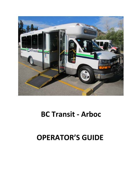
<strong>BC</strong> <strong>Transit</strong> ‐ <strong>Arboc</strong>OPERATOR’S GUIDE
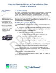
DRIVER’S COMPARTMENTBattery DisconnectThe battery disconnect switch (A) is located in the foot well area inside the driversdoor. Move the rotary disconnect switch to the OFF position while the bus is not inuse. This will help prevent the chassis batteries from being depleted by an accessoryin the bus left on. Move the rotary switch to the ON position for use and OFF forstorage.Figure 1 – Battery Disconnect Switch NOTICE Do notattempt to operate the bus with the disconnect switch in the off position.In the off position, the chassis engine will start and run, but busfunctions including park interlock, power door, ramp, interior lamps, etc.are inoperable.Window breaker located on the side of the driver seat
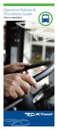
Figure 2 – ARBOC Installed ControlsA – RadioB – Security Radio System (If applicable)C ‐ARBOC Mobility Control PanelD ‐ Power Heat RampE – Master Power (Power switch when engine not running)F – Passenger Floor LightMirror Directional ControlsMirror Heat SwitchMirror Directional SwitchMirrors are heated when this switch is activated. Pressing the switch will turn mirrorheat on and switch will return to its original position when activated. Mirror heat willautomatically shut off after a period of time
ARBOC Mobility Control PanelThis panel controls all major bus functions.A B C D E F G H IA – Power Ramp SwitchB – Kneeling SwitchC‐ Fast Idle SystemD – Rear Heat Fan SwitchE – Power Ramp DisplayF – <strong>Bus</strong> Climate Control SwitchG‐ <strong>Bus</strong> Climate Control Temperature SettingH – Door Open/Close SwitchI – Interior Lights Master Switch (this switch must be on for the bus interior tofunction)
(H) ‐ Door Switch OperationTo open the door, press and hold the door switch until the door is fully open. At thefully open position, the lights in the passenger door entrance will come on. This isconfirmation the door is fully open. If the door switch is released at any time duringthis operation, the door will stop. This is a safety feature that allows the operator tostop the door at any time.(B) – Kneeling SwitchTurning the kneeling switch off will disable the air/ kneeling function. DO NOT turn offkneeling function while bus is kneeled with the doors open. Doing so will raise thesuspension from the kneeled position to normal ride height, causing an abrupt changein step height for passengers entering or exiting.The door will stop in any partially open position if pressure is removed from theswitch prior to being fully open.Depressing the switch to the CLOSE position signals the air system to refill the air bags(unless equipped with optional Kneel ON/OFF switch in the OFF position) and willclose the door as long as the switch is depressed.Refer to the Trans/Air <strong>Manual</strong> provided with your bus.(D) Rear Heat Fan SpeedThe rear heat fan speed switch (D) controls the heater fan located in the rear of thebus.Figure 4 – Rear Heat Fan SwitchPress the top of the switch for high, the center for off and the bottom for low speed.
(E) IntelligentPower RampDisplayThis display will indicate the necessary conditions have been met to deploying theramp.Intelligent Interlock DisplayIndicates that all safety conditions have been met and it is safe to deploy rampwhen illuminated. B – Indicates door is fully open when illuminated. C – Indicatesparking brake is set when illuminated. D – Indicates transmission shift lever is inpark when illuminated. E – Indicates ramp is stowed when illuminated. (Same as“A” above if equipped with a manual ramp.)(C) Fast Idle SystemThe fast idle system can automatically increase engine speed to 1500 rpm for up to 15minutes or until the operator releases the parking brake or steps on the brake pedal.The fast idle system receives inputs from the parking brake, transmission, engine andcharging system to determine iffast idle is needed.This display will indicate the status of the fast idle system and also allow the operatorto manually select fast idle.
Power RampRisk of personal injury or bus damage. Do not attempt to operatecontrols on panel until a clear path for the doors and ramp is confirmed.1. Bring the bus to a complete stop.Note: The indicator lamps on the “intelligent lift interlock system” panel will light aseach step below is performed.2. Press the brake pedal and shift transmission into PARK.3. Set the Parking Brake. The engine should be running for best performance.Interlock DisplayA – Indicates that all safety conditions have been met and it is safe to deploy rampwhen illuminated. B – Indicates door is fully open when illuminated. C – Indicatesparking brake is set when illuminated. D – Indicates transmission shift lever is in parkwhen illuminated. E – Same as “A”4. Press and hold the door switch on the dash to open the door. You must HOLD thisswitch to completely open the door. The ramp area lights will be lit when the dooris in the fully opened position.Risk of personal injury or bus damage. Do not attempt to deploy rampuntil a clear path for the ramp is confirmed.
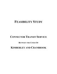
5. Once your passengers are clear of the ramp area, press the power ramp switchmounted outside in front of door.*Do not attempt to deploy the ramp until a clear path for the ramp is confirmed *. Outside Ramp and door switch (Located here)
6. Once everyone is clear, stow the ramp with the outside switch.7. Press and hold the door switch on the dash to close the door.8. Release the Parking Brake. <strong>Bus</strong> is now ready for normal operation.<strong>Manual</strong>ly Releasing the RampIn the event the loading ramp is inoperable, please follow these steps1. Bring the bus to a complete stop.2. Press the brake pedal and shift transmission into Park3. Set the Parking Brakes.4. Press and hold the door switch on the dash to open the door. You musthold this switch to completely open the door. The ram area lights will belit when the door is in the fully opened position.5. Pull the “T” handle located on the right side of the ramp6. Grasp the open handle and pull out on the ramp*Do not attempt to deploy the ramp until a clear path for the ramp is confirmed *
Emergency Exits WindowTo open the emergency roof exit, rotate red latch (B) to exit and pushup on roof exit.Your bus is equipped with three emergency exit windows (located at the rear and oneon each side) and may be equipped with one emergency exit in the roof. To open theemergency exits windows, rotate red handles (A) and push window out.Emergency Roof ExitTo open the passenger door in an emergency, pull red handle (B) out and push door open.
AIR RIDE SYSTEMThe fully automatic air ride system provides the capability to kneel each time the buspassenger door is opened and return the bus to proper ride height when the door isclosed.The Spirit of Mobility vehicle air ride system is composed of 6 major components; aircompressor, air dryer, air reservoir, control system, air lines and air bags. Adescription and functions of these components follows.Air CompressorThe engine‐mounted air compressor is driven by the engine crankshaft through aserpentine belt. Power is transferred from the belt to the air compressor through anelectrical clutch similar to an air conditioning clutch mechanism. The electrical clutchis activated by a system pressure switch located in the air reservoir tank. Thus, the aircompressor is in operation only when the system pressure drops below a set value.The air compressor contains its own lubrication and oil reservoir tank.Air DryerCompressed air is routed from the air compressor to the air dryer located on thedriver’s side frame rail. The compressed air is routed through the dryer prior toflowing to the reservoir tank.Air ReservoirThe air reservoir is mounted on the driver’s side of the vehicle just ahead of the rearaxle. The reservoir is sized with sufficient capacity to completely fill the air bags oneand a half times in case of air compressor failure. Mounted on the air reservoir tank isa manually activated drain valve to dispense with any water that may accumulate inthe reservoir tank.
The control system is made up of the following components:• System Control /Air Distribution ModuleMounted on the driver’s side frame rail just rearward of the air dryer, thesystem control/ air distribution module is calibrated to provide electricalsignals to the solenoids that direct system air from the air reservoir tankto the front and rear air bags. The control module is activated by thedoor’s Open/Close switch mounted in the vehicle control panel and thevehicle ride height sensors. The door switch activates vehicle kneeling,which will either fill or exhaust the air in the air bags. The noise you hearwhen the door “open” position is activated is the air in the systemexhausting to atmosphere depleting the air in the air bags causing thevehicle to kneel. The system refills the air bags to obtain the correctvehicle ride height when the door “close” position is activated.• Vehicle Ride Height SensorsWith one for the front axle and one at each side of the rear axle, thevehicle ride height sensors provide data to the control module for propervehicle ride height. Ride height sensors and adjustment rods are set atthe factory and adjustments to these components are not requiredduring normal vehicle life cycle operation.Side tie down strapsBack up sensor switch