Catalog â Components - Allied Automation, Inc.
Catalog â Components - Allied Automation, Inc.
Catalog â Components - Allied Automation, Inc.

You also want an ePaper? Increase the reach of your titles
YUMPU automatically turns print PDFs into web optimized ePapers that Google loves.
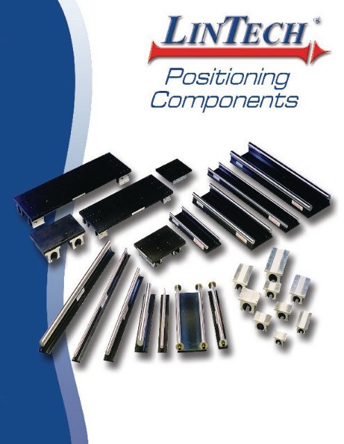
Welcome to LINTECHOur local technical support group consists of<strong>Automation</strong> Specialists located throughout the World.These <strong>Automation</strong> Specialists are experienced inthe use of electronic and mechanical motion controlproducts. They are well trained on the performancecapabilities of LINTECH positioning components.LINTECH is constantly designing new productsand improving upon the many options available withour standard products. Whether it is a standard orcustom positioning system required, please write,call, or e-mail us. We look forward to hearing fromyou.Visit our website, or call for the nearest <strong>Automation</strong>Specialist in your area:For over 36 years LINTECH has designed,engineered, and manufactured linear positioningcomponents for use in a wide range of applications.Whether it is a standard positioning component or acustom positioning assembly, LINTECH takes greatpride in manufacturing a quality product.At LINTECH we are proud to provide the motioncontrol user with this product guide. It wasdeveloped to assist you with the design, selection,and implementation of mechanical positioning components.Depending on the requirements, standard positioningcomponents can often be assembled andshipped in less than 2 weeks. Custom positioningassemblies require a different approach. We evaluateyour special application, use our many years ofexperience to guide you, and then manufacture aquality product designed to meet your performancespecifications.Toll Free:Phone:Fax:Web Site:e-mail:LINTECH ®1845 Enterprise WayMonrovia, CA. 91016(800) 435 - 7494(626) 358 - 0110(626) 303 - 2035www.LintechMotion.comLintech@LintechMotion.comRegistered by UL to ISO 9001:2000Certificate No. A6916LINTECH's technical support consists of a welltrained inside customer service department, an experiencedapplication engineering staff, and a versatilemachining facility that is ISO 9001:2000 certified.version: 02/2007Copyright © 2007 LINTECH
Design ConsiderationsProduct DescriptionPrecision Steel ShaftsLINTECH's SL shafting and SA and TRSA shaft assembliesuse Rockwell 60-65C hardened and ground steelshafts as the inner race in this highly reliable linear bearingsystem. These high quality carbon steel shafts are accuratelymachined and precisely heat treated for uniform hardness.They are also inspected for straightness, roundness, andsmoothness. The high hardness and extremely smooth surfaceof the steel shafts creates an abrasion-resistant surface,which reduces material wear and system friction, whilemaintaining an optimal surface finish.Shaft Assembly SupportsLINTECH shaft assemblies (SA and TRSA series) use6061-T6 precision machined aluminum supports. Theseblack anodized supports have pre-drilled base mountingholes that come in both single supports for the SA, andTWIN RAIL ® supports for the TRSA. These precision machinedsupports come in 6, 12, 18, and 24 inch lengths, andcan be combined for nearly unlimited assembly lengths.SA Series - single rail supported asemblyAStainless Steel ShaftsFor corrosion resistant applications, LINTECH provides440C stainless steel shafts with the same shaft diametertolerance, hardness depth, and straightness as our standardsteel shafts. Stainless steel shafts are recommended for usein chemical and food processing industries, for medicalequipment in corrosive environments, or in strong oxidizingatmospheres where no lubricating oil is available.Chrome Plated Bearings & CarriagesLINTECH can also provide corrosion resistant linear bearingsand shafts. All metal hardware is either stainless steelor chrome plated.Pre-Mounted ShaftBase Mounting HolesTRSA Series - TWIN RAIL ® supported assemblyPre-Mounted &Pre-Aligned ShaftsBase Mounting HolesShaft Diameter ToleranceLINTECH shafts are precision ground to a very closediameter tolerance. This diameter tolerance is an extremelyimportant factor when using LINTECH linear bearings. Itassures a dependable fit, with proper clearance between ashaft assembly and linear bearing.Shaft HardnessThe hardness of a steel shaft is its ability to prevent nicks,indentations, or grooving. It is an important factor in determiningthe life of a linear bearing system in an application.The heat treatment process performed on all shafts assuresuniform hardness in radial and axial directions.Hardness DepthShaft Component SupportsLINTECH ES end supports use 6061-T6 aluminum (-A),or 1045 steel (-S). These supports slide over the hardenedshaft, and have a screw that is adjusted to "clamp" thesupport onto the shaft. The assembly support (ARS series)is manufactured from aluminum. The low profile support(LSRS series) is manufactured from C-1018 steel and functionsthe same as the ARS series, but has a smaller overallheight. The LSRS is the only support that is mounted fromthe mounting surface "up".ES-A SeriesES-S SeriesBase Mounting HolesARS SeriesLSRS SeriesShaft StraightnessThe exceptional straightness of all shafts eliminate systembinding when using a TRSA shaft assembly with a TRCAcarriage assembly, and helps the alignment process whenusing two SL shafts, or SA shaft assemblies, in a parallelassembly application.Base Mounting HolesLINTECH ®Positioning <strong>Components</strong>A-5
Design ConsiderationsHow to Select a Positioning ComponentTravel LifeThe rated life of a linear bearing or carriage assembly ismeasured in inches (or km) of travel under a specified load.The failure of a linear bearing system occurs when the operatingstresses from the rolling balls in the linear bushingcause material fatigue, resulting in flaking of the steel ballsor steel shaft and/or grooving in the steel shaft.Every linear bearing or carriage assembly has a dynamicload rating associated with it based on a L 10life of 2 millioninches of travel (approximately 50 km). For most applications,knowing the load applied to a bearing and the liferequired is all that is needed in selecting the proper componentsfor the task at hand.LINTECH has provided examples, equations, and graphsto determine what the estimated life will be based upon anapplied load and application conditions for product seriesshown in this catalog. This allows quick selection of a linearbearing or carriage assembly for most applications.For these applications the dynamic load rating along withseveral other application factors may need to be reviewed.The hardness of the shaft used, operating temperature, directionof the load, additional shock loads, and linear speed ofthe pillow blocks are all factors that should be considered.This allows for an accurate prediction of the dynamic life ofa linear bearing in a specific application.Load RatingsThe applied load that a linear bearing or carriage assemblywill see needs to be compared against the load capacity ofthat component. The dynamic load rating of a linear bearingor carriage assembly pertains to the component in motionand this load rating is based on the number of inches (orkm) traveled.Required Life ExamplesBelow are two examples which illustrate the importanceof a dynamic load rating based upon travel life. These twoapplications could lead to the selection of different componentsdue to the difference in the number of required inchesof travel, even though the the applied load is the same 150lbs (68 kg).Example 1:assembly needs to last 6 yearswitha 10 inch move out, then back 10 inches every 90 secondsfor8 hours per dayfor5 days per weekand50 weeks per year(10 x 2) inches90 sec5 days1 weekExample 2:(24 x 2) inches30 secXXX60 sec1 min50 weeks1 yr60 sec1 minX60 min1 hrX8 hr1 dayX 6 years = 9,590,400inches of travelassembly needs to last 8 yearswith(24) 1 inch moves out, then back 24 inches every 30 secondsfor12 hours per dayfor7 days per weekand52 weeks per yearX60 min1 hrX12 hr1 dayXXARequired LifeIt is important to evaluate the required or expected life froma linear bearing for a given application load. This requiredlife is specified by the user as the desired life prior to a possiblefailure. This period of time (usually in years) then willneed to be converted into a travel distance (typically inchesor km) to select the appropriate size linear bearing.7 days1 weekX52 weeks1 yrX 8 years = 201,277,440inches of travelLINTECH ®Positioning <strong>Components</strong>A-7
Design ConsiderationsSafety FactorsAs a practice, safety factors should always be used whenselecting a linear bearing or carriage assembly for a givenapplication. For most real world applications people do usesafety factors. However, sometimes the incorrect safetyfactor or no safety has been used. This can lead into anunexpected system failure. LINTECH provides, in a chartform, different safety factor recommendations for linearbearings or carriage assemblies. Keep in mind that theserecommendations for safety factors are not hard and fastrules. Safety factors for a specific linear bearing may haveto be increased or decreased based upon the applicationrequirements.Linear Bearing Load CapacitiesLinear Bearing Load Capacities are specified with a dynamicvalue. These values are used to help select the properlinear bearing or carriage assembly size for a given load/lifeapplication. The use of adequate safety factors is a keyelement in the selection process of a linear bearing systemfor a given application. Selecting a bearing with no safetymargin can lead to problems relating to performance andlong term life.Dynamic Loads exert a force upon the linear bearings orcarriage assembly while in motion. Every linear bearing orcarriage assembly has a load capacity associated with it thatis based upon the number of inches (or km) traveled. If theload applied to the carriage is less than the rated value at 2million inches (or 50 km) of travel, the linear bearings willhave a longer life associated with them that is exponential.Therefore, to properly select a linear bearing or carriageassembly that will last the required travel life for an application,the forces acting upon the linear bearings need to bereviewed. Once the force on the heaviest loaded bearing hasbeen determined and a proper safety factor selected, thenthe life of that bearing or carriage assembly can be determinedby using a simple mathematical equation.Even though the forces acting upon a bearing or carriage assemblycan be calculated, other parameters such as changingloads, speeds, acceleration rates, environments, and lack oflubrication produce extra forces (stresses) that are hard toquantify. As a bearing moves, there are additional resultantloads as a by-product. The rate at which the bearing beginsto move a load can have a large impact on its life. Thelinear bearings see this start/stop rate as a shock load eachtime. These and other variable loads cannot be calculatedprecisely. Thus, a safety factor should be applied to accountfor these loads which could fatigue the system and causepremature failure. See the below chart as a guideline.Impacts orVibrationNoneSmallMediumLargeRecommended Linear Bearing Dynamic Safety FactorsVery LargeSpeed(in/sec)Min. SafetyFactor - S< 5 < 0.25 1.0 - 2.05 - 1010 - 20Safety Factor ExampleAcceleration(G's)0.25 - 0.5020 - 50 1.00 - 1.50Load Capacities2.0 - 3.00.50 - 1.00 3.0 - 4.04.0 - 6.0> 50 > 1.50 6.0 - 8.0Application calls for an external 1,500 lbs of force to beapplied to a part (weight = 100 lbs) that is mounted to acarriage assembly. The system will be at rest. There willbe a small impact to the part (and carriage assembly) asthe force is first being applied.totalloadFrom chart 1 - use a 3.5 factorfactorselect a carriage assembly thathas a static capacity greaterthan this value(1,500 + 100) x 3.5 = 5,600 lbsA-8LINTECH ®Positioning <strong>Components</strong>
Design ConsiderationsLoad CapacitiesHardness factor - F HThe maximum travel life of a linear bearing is achievedwhen the shaft surface has a hardness value greater than (>)Rockwell 60C. This hardness assures that no shaft groovingor flaking will occur under normal operating conditions.LINTECHSL & SA & TRSAstandard shaftsstainless steel shaftschrome plated shaftsRockwellHardness60-65C50-55C67-72CF Hfactor1.00.521.00When using LINTECH bearings, pillow blocks, or TRCAcarriage assemblies with different shafting and hardnessratings, refer to the Shaft Hardness graph below for thecorrection factor.1.00.9Hardness factor - F HTemperature factor - F TAmbient temperatures over 212 0 F (100 0 C) will fatigue thelinear bearings, or carriage assembly, and will cause a decreasein travel life. LINTECH's linear bearings or carriageassemblies have a maximum operating ambient temperatureof 185 0 F. Therefore these bearings, or carriage assemblies,should never be used in ambient temperatures above 185 0F. Custom linear bearings or carriage assemblies, can beprovided for higher temperature applications.LINTECHLinear BearingsCarriage AssembliesMaximumOperating Temp.185 0 F185 0 FF TfactorWhen using LINTECH's SL shafting, SA, or TRSA shaftassemblies with different linear bearings and temperatureratings, a temperature correction factor may be required ifthe ambient temperature exceeds 212 0 F (100 0 C). Refer tothe Temperature graph below for the correction factor.11AHardness factor - FH0.80.70.60.50.40.30.20.160 50 40 30 20 10Temperature factor - FT1.00.90.80.70.6Temperature factor - F TShaft Hardness (Rockwell C)100 0 C212 0 F120 0 C248 0 F140 0 C284 0 F160 0 C320 0 F180 0 C356 0 F200 0 C392 0 FAmbient TemperatureLINTECH ®Positioning <strong>Components</strong>A-9
Design ConsiderationsLoad CapacitiesLoad direction factor - F LThe maximum travel life of a linear bearing or carriage assemblymay need to be derated depending upon the directionof the load as applied to the bearing. The Polar Chartsshown for each bearing type indicate the derating factor (ormultiplier) based upon the direction of the load applied tothe linear bearing. Not all bearings will see the same loaddirection, so you can use the adjacent equation to determinethe estimated life based upon the "heaviest" loaded bearingor the one which requires the greatest derating factor. Thiswill yield a life value showing the bearing which has thelowest overall travel length or life rating.To use the below graphs, simply find the intersecting pointbased upon the direction of the load (that the bearing sees)and then use the derating factor (i.e. 0.9, etc.), if any.L =F H x F T x F L xRF x SL = normal travel life millions of inches (or Km)R = rated dynamic load capacity of linear bearing, orcarriage at 2 million inches of travel (or 50 Km)F = user applied loadB = either 2 millions of inches (or 50 Km)F H= shaft hardness factorF T= environment temperature factorF L= load direction factorS = dynamic safety factor3xB90 90 901.31.1.9.7.51.31.1.9.7.51.31.1.9.7.5180 018001800.5.7.91.11.3LBC-4LBC-6LBC-8, SLBC-8, DLBC-8.5.7.91.11.3LBC-10, SLBC-10, DLBC-10.5.7.91.11.3LBC-12, SLBC-12, DLBC-12LBC-16, SLBC-16, DLBC-16LBC-20, SLBC-20, DLBC-20LBC-24, SLBC-24, DLBC-24LBC-32, SLBC-32901.31.1.9.7.5901.31.1.9.7.518001800.5.7.91.11.3LBO-8, SLBO-8, DLBO-8LBO-10, SLBO-10, DLBO-10.5.7.91.11.3LBO-12, SLBO-12, DLBO-12LBO-16, SLBO-16, DLBO-16LBO-20, SLBO-20, DLBO-20LBO-24, SLBO-24, DLBO-24LBO-32, SLBO-32Specifications subject to change without noticeA-10LINTECH ®Positioning <strong>Components</strong>
Design ConsiderationsLoad CapacitiesLubricationLINTECH shaft assemblies, linear bearings, or carriage assembliesrequire a small amount of grease or oil for proper,long term operation. Lubrication will decrease system wearand the potential for rusting of shafts and linear bearingsurfaces. For most applications a medium to heavy oil, lightgrease, or silicone based lubricant is recommended. Themany built-in pockets within the linear bearing allows theadhesive properties of these lubricants to be stored for extendedperiods of time while minimizing sealing problems.To obtain the estimated travel life for a given application,the linear bearings or carriage assemblies should not run dryfor an extended period of time. This lubrication schedulewill ultimately need to be determined empirically duringoperation at the installation site since it can vary dependingupon the environment, operation conditions, quantity andtype of lube used, and other unforeseen conditions.All LINTECH shaft assemblies, linear bearings, and carriageassemblies are shipped lightly coated with a rustpreventative oil in the bearings or on the shafts. This willhelp prevent corrosion during the shipping period of theproduct. It is highly recommended that all shaft assemblies,linear bearings, and carriage assemblies be lubricated duringinstallation or prior to operation. Also, periodic re-lubricationof the linear bearings, or carriage assembly, and shafts,will help assure that the rated life of the system is obtained.Additional details on all LINTECH shaft assemblies, linearbearings, and carriage assemblies are available from theService Manual. This manual discusses the recommendedlubrication and provides additional important guidelines forfrequency of lubrication based upon several conditions.NOTE: Use of WD-40 or other cleaning solvents shouldstrictly be avoided as they can cause damage to the linearbearing and shaft.Frictional ResistanceThe total friction resistance of a LINTECH linear bearingor carriage assembly can be calculated by using the followingequation.R =RWx+F s= Frictional resistance (lbs)W = Load weight (lbs)F s= coefficient of friction= Frictional resistance - seal drag (lbs)Note: LINTECH recommends using = .01 for alllinear bearing and carriage assemblies series.The coefficient of friction ( ) of a LINTECH linearbearing or carriage assembly consists of the rolling (operating)friction, and the static (breakaway) friction. Two mainfactors affect the coefficient value. The type of lubricationused (i.e. oil, grease, or none) and the ratio between thetotal load weight and the dynamic load rating of the linearbearing or carriage assembly used.For most applications, LINTECH recommends using avalue of .01 for the coefficient of friction. This value can beused for all linear bearings or carriage assemblies. The .01value provides for an adequate safety margin when evaluatingsystem performance. Other frictional resistances of aLINTECH linear bearing are seal drag and system preload.While wiper seals are used to retain lubricants and to prevententry of foreign particles into the linear bearing, theywill increase the frictional resistance of the system. <strong>Inc</strong>reasingthe preload of a linear bearing will also add extra frictionalresistance. The chart below lists the nominal values ofthe LINTECH linear bearings or carriage assemblies.Frictional Resistance - F s (seal drag)AModel NumberF s(lbs)Model NumberF s(lbs)xLBC or xLBO-8xLBC or xLBO-10xLBC or xLBO-120.50.40.4TRCA-8-xxTRCA-10-xxTRCA-12-xx2.01.61.6xLBC or xLBO-16xLBC or xLBO-20xLBC or xLBO-24xLBC or xLBO-320.45.07.08.0TRCA-16-xxTRCA-20-xxTRCA-24-xxTRCA-32-xx1.620.028.032.0DLBC or DLBO-8DLBC or DLBO-10DLBC or DLBO-120.50.40.4TRCA-8-6TRCA-10-6TRCA-12-61.00.80.8DLBC or DLBO-16DLBC or DLBO-20DLBC or DLBO-240.45.07.0TRCA-16-6TRCA-20-8TRCA-24-12x = blank for LBC/LBO, x = S for SLBC/SLBOxx = 12, 18, 24, or 30 inch carriage lengths0.810.014.0Specifications subject to change without noticeLINTECH ®Positioning <strong>Components</strong>A-11
Design ConsiderationsLoad CapacitiesRated Load CapacityThe dynamic load capacity of all LINTECH LBC,LBO, SLBO, SLBC, DLBO and DLBC linear bearingsis based upon having the load forces centered on thebearing with the load force in the 90 degree location(directly down on the top of the bearing) per the PolarCharts shown on page A-10.The rated values are based on a L 10 life of 2 millioninches of travel (or 50 km). For a given bearing, as loadforces decrease, the life of the bearing will increaseexponentially. The actual life of a linear bearing orcarriage assembly used in an application, can be determinedby reviewing the load and life considerationsfound on pages A-7 to A-10.FFFFLBCSLBC & DLBCLBOSLBO & DLBOLBC, SLBC & DLBC Linear BearingsModelNumberLBC-4LBC-6xLBC-8xLBC-10xLBC-12xLBC-16xLBC-20xLBC-24xLBC-32DLBC-8DLBC-10DLBC-12DLBC-16DLBC-20DLBC-24NominalShaft Dia.(inches)0.2500.3750.5000.6250.7501.0001.2501.5002.0000.5000.7501.0001.2501.500Dynamic Load (1)Capacity(lbs)2654206401,0451,5851,9300.625 840x = blank for LBC, x = S for SLBC601053,0005101,2802,0903,1703,860LBO, SLBO & DLBO Linear BearingsModelNumberxLBO-8xLBO-10xLBO-12xLBO-16xLBO-20xLBO-24xLBO-32DLBO-8DLBO-10DLBO-12DLBO-16DLBO-20DLBO-24NominalShaft Dia.(inches)0.5000.6250.7501.0001.2501.5002.0000.5000.6250.7501.0001.2501.500x = blank for LBO, x = S for SLBODynamic Load (1)Capacity(lbs)2303204707801,1701,5602,3504606409401,5602,3403,120Footnotes:(1) Rating is based upon 2 million inches of travel and with the load forces being applied downward on the linear bearing, while in a horizontal application.Specifications subject to change without noticeA-12LINTECH ®Positioning <strong>Components</strong>
Design ConsiderationsLoad CapacitiesRated Load CapacityThe dynamic load capacity of a LINTECH TRCAcarriage assembly is based upon having the loadforces centered on the carriage and the combineddynamic load capacity values of the SLBO or DLBOlinear bearings used. The rated values are based on aL 10 life of 2 million inches of travel (or 50 km) andwith the load forces applied downward onto the carriageassembly.Load Centered on CarriageFLoadLoadAFor a given carriage assembly, as the load force decreases,the life of the carriage assembly will increaseexponentially. The life of a carriage assembly, usedin an application, can be determined by reviewing theload considerations found on pages A-7 to A-10.Rated Moment LoadsWhen using a LINTECH TRCA carriage assemblyin an application, a moment load exists when the loadcenter of gravity is located away from the center ofthe carriage assembly. The life of a carriage assemblyis determined by the heaviest loaded linear bearing.Follow the steps below to determine if a specificTRCA carriage assembly will operate sufficiently in agiven application.Step 1: Calculate the forces acting on each of theindividual bearings for a given configuration andTRCA carriage assembly by using the equations onpage A-15.Step 2: Compare the calculated values with the rateddynamic load capacity values for the SLBO or DLBOlinear bearings used on the TRCA carriage assembly.Make sure the calculated values are below the ratedvalues. Note: If the calculated forces are acting onthe open end of a linear bearing, reduce the rateddynamic load capacity of that bearing by as shown onthe Polar Charts found on page A-10.Step 3: Follow the information on pages A-7 throughA-10 to determine the theoretical travel life of theselected carriage assembly in inches (or km) of travel.M RM PLoadLoadFLoad Center away from Carriage CenterM RLoadLoadLoadM RM PLoadLoadM YLoadLINTECH ®Positioning <strong>Components</strong>A-13
Design ConsiderationsLoad CapacitiesTRCA Rated Load CapacityThe LINTECH TRCA series, TWIN RAIL ® carriage assemblyconsists of (2) DLBO series or (4) SLBO seriesmounted to a precision machined plate. The bearing pillowblocks are mounted, aligned, and doweled in-place.They are designed to mate directly with the LINTECHTRSA series, TWIN RAIL ® shaft assemblies. Usingthese series in combination will eliminate the requirementto align and set-up the assemblies to be paralleland operate smoothly.Typical TRCA Carriage Assemblyd 2d rd rTRCA Carriage Assembliesd 2ModelNumberNominalShaft Dia.(inches)CarriageLength(inches)LinearBearingUsedEach Bearing (1)Dyn. Load Capacity(lbs)Dyn. Load (1)Capacity(lbs)d r(inches)d 1(inches)d 2(inches)TRCA8-6TRCA8-12TRCA8-180.5000.5000.5006.0012.0018.00DLBOSLBOSLBO2302302309209209201.0621.0621.0623.003.003.001.9010.0016.00TRCA10-6TRCA10-12TRCA10-180.6250.6250.6256.0012.0018.00DLBOSLBOSLBO3203203201,2801,2801,2801.2501.2501.2503.753.753.752.159.7515.75TRCA12-6TRCA12-12TRCA12-180.7500.7500.7506.0012.0018.00DLBOSLBOSLBO4704704701,8801,8801,8801.4371.4371.4374.504.504.502.509.6215.62TRCA16-6TRCA16-12TRCA16-18TRCA16-241.0001.0001.0001.0006.0012.0018.0024.00DLBOSLBOSLBOSLBO7807807807803,1203,1203,1203,1201.6871.6871.6871.6875.255.255.255.253.258.8714.8720.87TRCA20-8TRCA20-12TRCA20-18TRCA20-241.2501.2501.2501.2508.0012.0018.0024.00DLBOSLBOSLBOSLBO1,1701,1701,1701,1704,6804,6804,6804,6802.2502.2502.2502.2506.006.006.006.003.908.1214.1220.12TRCA24-12TRCA24-18TRCA24-24TRCA24-301.5001.5001.5001.50012.0018.0024.0030.00DLBOSLBOSLBOSLBO1,5601,5601,5601,5606,2406,2406,2406,2402.7502.7502.7502.7506.626.626.626.625.0013.7519.7525.75TRCA32-18TRCA32-24TRCA32-302.0002.0002.00018.0024.0030.00SLBOSLBOSLBO2,3502,3502,3509,4009,4009,4003.3753.3753.3757.257.257.2512.7518.7524.75Footnotes:(1) Rating is based upon 2 million inches of travel and with the load forces being applied downward on the linear bearing, while in a horizontal application.Specifications subject to change without noticeA-14LINTECH ®Positioning <strong>Components</strong>
Design ConsiderationsAll individual bearing force equations below pertainto a four bearing carriage which is at constant uniformvelocity or with the carriage at rest. During accelerationand deceleration intervals of a positioning system,the force exerted upon an individual bearing changesas the acceleration or deceleration rate varies. In mostcases, the extra force acting upon an individual bearingduring the acceleration interval is offset by a reducedforce during the deceleration interval. Therefore, usingjust the constant uniform velocity equations willadequately determine the life of an individual bearingfor a particular application.d 1d 2d 3d 4F BXF BYF BZW- distance between center lines of shafts or rails (in)Load Capacities- distance between center lines of linear bearing blocks (in)- distance between carriage center and load center of gravity (in)- distance between carriage center and load center of gravity (in)d r - distance between carriage surface and linear bearings (in)- force acting upon bearing in X-axis direction (lbs)- force acting upon bearing in Y-axis direction (lbs)- force acting upon bearing in Z-axis direction (lbs)- load weight (lbs)AHorizontal ApplicationsW Example #1d 4d 31 2WExample #2d 41W2d 3d 1 d 13 4 3 4d 2d 2WF 1Z F 3Z F 2Z F 4ZF 2Z F 4ZF 1Z=W4+F 2Z=W4-F 3Z=W4+W2W2W2xxxd 4d 2d 4d 2d 4d 2++-W2W2W2xxxd 3d 1d 3d 1d 3d 1F 4Z=W4W d 4- x -2d 2W2xd 3d 1Side Mounted ApplicationsVertical ApplicationsWd 4 W d 3F 1 ZF 2Zd rWd 4d rd 11 23F 3ZF 4Zd 14d 2F 1Y F 2YF 3Y F 4YF 3Yd 2 F 3Xd 3F 4YF 4XW W d 4F 1Z= F 3Z= + x4 2F 2Z=F 4ZW W= - x4 2d 2d 4d 2F 1Y F 3Y=W2xd 3d 1+ d rW d 4 + d rF 1X F 3X= x2F 1X+ F 3X F 2X+ F 4Xd 2F 1XF 1Y F 3Y F 2Y F 4YF 1Y F 3Y=+W2x+d 3d 2Mean Bearing Load CalculationWhen the force acting upon an individual bearing varies,as is the case with the bottom axis bearings of a multiaxespositioning system, a mean bearing load calculationdetermines the life of that bearing.F avg ( F min + 2 x F ) max=13F max - maximum force acting upon bearing (lbs)F avg - average force acting upon bearing (lbs)F min - minimum force acting upon bearing (lbs)LINTECH ®Positioning <strong>Components</strong>A-15
Design ConsiderationsLoad CapacitiesDeflectionThe equations below can be used when applying LINTECHclosed linear bearings (LBC, SLBC, or DLBC series), casehardened shafting (SL series), with shaft end supports (ESseries), or with threaded shaft ends attached to a plate oneach end. The estimated deflection that a configuration willexperience is dependent upon the shaft diameter, unsupportedshaft length, shaft material, and the type and numberof bearings being used.Minimizing the deflection of the components will reduceadditional stresses which can lead to premature failure.Excessive deflection can cause binding or rough operationwhen the bearings are at the area of travel furthest from thesupported portion (mid-stroke).ModelNumberSL4SL6SL8SL10SL12SL16SL20SL24SL32NominalShaftDiameter(inches)0.2500.3750.5000.6250.7501.0001.2501.5002.000ShaftWeightT(lbs/in)0.0140.0310.0550.0860.1250.2220.3480.5000.890StrengthFactorS k(psi)5,70029,10091,800224,400465,0001,470,0003,594,0007,455,00023,562,000One (1) bearing per shaft1/ 2 LLWL 3D = +48 Sk5TL 4384 SkTwo (2) bearings per shaftLS k= strength constant - modulus of elasticity x moment of inertiaC CW2W2D =WC(3L 2 - 4C 2 ) 5TL 4+48 Sk 384 SkD = deflection (inches)W = user applied load (lbs)L = length of unsupported shaft (inches)C = distance from support to center of first bearing (inches)T = total weight of unsupported shaft length (lbs)A-16LINTECH ®Positioning <strong>Components</strong>
LBC, LBO, SLBC,SLBO, DLBC, & DLBOLinear Bearings and Pillow BlocksTRCA Carriage AssembliesBLinear Bearings Ordering GuideLBC & LBOSLBC & SLBODLBC & DLBO Series SpecificationsTRCA Series SpecificationsB-1B-2TRCA Ordering Guide B-6OptionsB-6B-9
Ordering GuideLBC, LBO, SLBC, SLBO, DLBC & DLBO SeriesLBC - 10 - S - CRLinear Bearing SeriesLBC - One linear bearing (closed)LBO - One linear bearing (open)Nominal Diameter4 - 0.250 inch diameter (only in LBC style)6 - 0.375 inch diameter (only in LBC style)8 - 0.500 inch diameter10 -12 -16 -0.625 inch diameter0.750 inch diameter1.000 inch diameter20 - 1.250 inch diameter24 - 1.500 inch diameter32 - 2.000 inch diameterWiper Seals- No sealsS - Seals at both endsBearing Options- StandardCR - Corrosion resistantPillow Block SeriesSLBC - One LBC bearing per pillow blockDLBC - Two LBC bearings per pillow blockSLBO - One LBO bearing per pillow blockDLBO - Two LBO bearings per pillow blockNominal Diameter8 - 0.500 inch diameter10 -12 -16 -Bearing Options0.625 inch diameter0.750 inch diameter1.000 inch diameter20 - 1.250 inch diameter24 - 1.500 inch diameter32 - 2.000 inch diameter (only in SLBC & SLBO style)- StandardCR - Corrosion resistantSLBC - 10 - CR - LBearing LockL- None- Hand wheel lockSpecifications subject to change without noticeB-1LINTECH ®Positioning <strong>Components</strong>
Technical ReferenceLBC, LBO, SLBC, SLBO, DLBC & DLBO SeriesSpecifications: LBC & LBO Linear BearingsOperating TemperatureMaximum SpeedBearing SealsShafting match0 o F to + 185 o F9 ft/secondOptional Wiper Seals on both endsSL, hardened & groundMating Housing/Pillow BlockC = clearanceP = preloadNominalShaftDiameter(inches)0.250Recommended Bore DiameterFixedHousing(inches).5005 / .5000AdjustableHousing(inches).5010 / .5000Bearing and Shaft Fit-up(before adjustment)FixedHousing(inches).0015C / .0000AdjustableHousing(inches).002C / .0000B0.375.6255 / .6250.6260 / .6250.0015C / .0000.002C / .00000.500.8755 / .8750.8760 / .8750.0015C / .0000.002C / .00000.6251.1255 / 1.12501.1260 / 1.1250.0015C / .0000.002C / .00000.7501.2505 / 1.25001.2510 / 1.2500.0015C / .0000.002C / .00001.0001.5630 / 1.56251.5635 / 1.5625.0015C / .0000.002C / .00001.2502.0008 / 2.00002.0010 / 2.0000.0018C / .0001P.002C / .00001.5002.3760 / 2.37502.3760 / 2.3750.0021C / .0000.0021C / .00002.0003.0010 / 3.00003.0010 / 3.0000.0023C / .0002P.0023C / .0001PSpecifications: SLBC, SLBO, DLBC & DLBO Pillow BlocksBearing Housing Type & FinishAluminum 6061-T6 Pillow Block, Clear AnodizedBearing SealsWiper Seals on Both EndsOperating TemperatureMaximum SpeedShafting match0 o F to + 185 o F9 ft/secondSL, hardened & groundDiameter ToleranceNominalShaft Diameter(inches)0.5000.6250.7501.0001.2501.5002.000Shaft DiameterTolerance(inches).4995 / .4990.6245 / .6240.7495 / .7490.9995 / .99901.2495 / 1.24901.4994 / 1.49891.9994 / 1.9987LINTECH ®Positioning <strong>Components</strong>Specifications subject to change without noticeB-2
Technical ReferenceLBC & LBO SeriesDimensions & Specifications: LBC Linear Bearing (closed)ModelNumberNominalShaftDiameter(inches)WorkingBoreDiameter(inches)(1) Dyn.LoadCapacity(lbs)ADimensions(inches)B CDBearingWeight(lbs)LBC-4 LBC-4-S 0.250 0.2500/0.2495 60LBC-6 LBC-6-S 0.375 0.3750/0.3745 105LBC-8LBC-10LBC-12LBC-16LBC-20LBC-24LBC-8-SLBC-10-SLBC-12-SLBC-16-SLBC-20-SLBC-24-S0.5000.6250.7501.0001.2501.5000.5000/0.49950.6250/0.62450.7500/0.74951.0000/0.99951.2500/1.24941.5000/1.49942654206401,0451,5851,930LBC-32 not available 2.000 2.0000/1.9992 3,0000.750/0.7350.875/0.8601.250/1.2301.500/1.4801.625/1.6052.250/2.2302.625/2.6000.511/0.500 0.039 0.5005/0.5000 0.010.699/0.6891.032/1.012 0.050 0.8755/0.8750 0.041.105/1.0951.270/1.2501.884/1.8642.004/1.9840.0390.0560.0560.0680.0680.6255/0.62501.1255/1.12501.2505/1.25001.5630/1.56252.0008/2.00000.020.100.140.250.453.000/2.970 2.410/2.390 0.086 2.3760/2.3750 0.854.000/3.960 3.193/3.163 0.105 3.0010/3.0000 1.45DWorking BoreDiameterBANominal ShaftDiameterCRetaining Ring GroovesDimensions & Specifications: LBO Linear Bearing (open)ModelNumberNominalShaftDiameter(inches)WorkingBoreDiameter(inches)(1)Dyn.LoadCapacity(lbs)ABDimensions(inches)CDEmin.BearingWeight(lbs)LBO-8LBO-10LBO-12LBO-16LBO-8-SLBO-10-SLBO-12-SLBO-16-S0.5000.6250.7501.0000.5000/0.49950.6250/0.62450.7500/0.74951.0000/0.99952303204707801.250/1.2301.500/1.4801.625/1.6052.250/2.2301.032/1.0121.105/1.0951.270/1.2501.884/1.8640.38LBO-20 LBO-20-S 1.250 1.2500/1.2494 1,170 2.625/2.600 2.004/1.984 0.068 2.0008/2.000058E30 o CRetaining Ring GroovesLBO-24 LBO-24-S 1.500 1.5000/1.4994 1,560 3.000/2.970 2.410/2.390 0.086 2.3760/2.375034 0.71LBO-32 not available 2.000 2.0000/1.9992 2,350 4.000/3.960 3.193/3.163 0.105 3.0010/3.000031 32 1.20ADWorking BoreBNominal ShaftDiameterDiameter0.0500.0560.0560.0680.8755/0.87501.1255/1.12501.2505/1.25001.5630/1.5625516387169160.030.080.120.21Footnotes:(1) Rating based upon 2 million inches of travel with the load forces being applied downward on the linear bearing, while in a horizontal application.Specifications subject to change without noticeB-3 22LINTECH ®Positioning <strong>Components</strong>
Technical ReferenceSLBC & SLBO SeriesDimensions & Specifications: SLBC Single Linear Bearing Pillow Block (closed)ModelNumberNominalShaftDiameter(inches)(1)Dyn.LoadCapacity(lbs)A+/- .003B C DDimensionsE+/- .010(inches)F+/- .010GHIholeJboltBlockWeight(lbs)SLBC-8SLBC-10SLBC-12SLBC-16SLBC-20SLBC-240.5000.6250.7501.0001.2501.5002654206401,0451,5851,9300.6870.8750.9371.1871.5001.7502.002.502.753.254.004.751.691.942.062.813.634.001.6882.1252.3752.8753.5004.1251.0001.1251.2501.7502.0002.500SLBC-32 2.000 3,000 2.125 6.00 4.50 3.63 5.250 3.250 4.50 4.06 .63 321.131.441.561.942.502.881.381.751.882.383.003.501.251.631.752.192.813.25.25.28.31.38.44.5053231631673273293213# 6 0.20# 8# 8#10#10140.500.601.202.503.8038 7.00BDAEBIHJF CNom. ShaftDiameterGAccess for Lubrication (2)Dimensions & Specifications: SLBO Single Linear Bearing Pillow Block (open)ModelNumberNominalShaftDiameter(inches)(1)Dyn.LoadCapacity(lbs)A+/- .003BCDimensionsD E F G H I J+/- .010(inches)+/- .010holeboltmin.KBlockWeight(lbs)SLBO-8SLBO-10SLBO-12SLBO-16SLBO-20SLBO-24SLBO-320.5000.6250.7501.0001.2501.5002.0002303204707801,1701,5602,3500.6870.8750.9371.1871.5001.7502.1252.002.502.753.254.004.756.001.501.751.872.623.373.754.751.131.441.562.002.562.941.6882.1252.3752.8753.5004.1251.0001.1251.2501.7502.0002.5000.690.880.941.191.501.7553231631673273293213 33.63 5.250 3.250 2.25 .63 1.00 2.4432# 6 .25 0.31 0.75 0.20# 8# 8#10#10148.28.31.38.44.500.370.430.560.620.750.941.001.251.631.880.400.501.002.103.206.00DABEIG K JPreloadAdjustingScrewHF CNom. ShaftDiameterAccess for Lubrication (2)Footnotes:(1) Rating based upon 2 million inches of travel with the load forces being applied downward on the linear bearing, while in a horizontal application.(2) Size 0.500 has oil lubricant fitting. Sizes 0.625 and above have a 1 / 4 -28 access for lubrication.Specifications subject to change without noticeLINTECH ®Positioning <strong>Components</strong>B-4
Technical ReferenceDLBC & DLBO SeriesDimensions & Specifications: DLBC Double Linear Bearing Pillow Block (closed)ModelNumberNominalShaftDiameter(inches)(1)Dyn.LoadCapacity(lbs)A+/- .003B C DE+/- .010Dimensions(inches)F+/- .010GHIholeJboltd 2(3)BlockWeight(lbs)DLBC-8DLBC-10DLBC-12DLBC-16DLBC-20DLBC-240.5000.6250.7501.0001.2501.5005109001,2002,1003,0004,0000.6870.8750.9371.1871.5001.7502.002.502.753.254.004.753.504.004.506.007.509.001.131.441.561.942.502.881.688 2.500 1.38 1.25 .255322.125 3.000 1.75 1.63 .282.3752.8753.5004.1253.5004.5005.5006.5001.882.383.003.501.752.192.813.25.31.38.44.50316316732732932# 6# 8# 8#10#10141.752.002.253.003.754.500.401.001.202.405.007.80DAEBIHJF CNominal ShaftDiameterGd 2Access for Lubrication (2)Dimensions & Specifications: DLBO Double Linear Bearing Pillow Block (open)ModelNumberDLBO-8DLBO-10DLBO-12DLBO-16DLBO-20DLBO-24NominalShaftDiameter(inches)D0.5000.6250.7501.0001.2501.500AG K(1)Dyn.DimensionsBlockLoad(inches)WeightCapacityA B C D E F G H I J K (3)(lbs)d (lbs)+/- .003+/- .010 +/- .010min. hole bolt2Screwd 2Access for Lubrication (2)460 0.687 2.00 3.50 1.13 1.688 2.500 0.69 .31 .25532 # 6 0.75 1.75 0.40640 0.875 2.50 4.00 1.44 2.125 3.000 0.88 .37 .28316 # 8 0.94 2.00 0.82940 0.937 2.75 4.50 1.56 2.375 3.500 0.94 .43 .31316 # 8 1.00 2.25 1.021,560 1.187 3.25 6.00 2.00 2.875 4.500 1.19 .56 .38732 #10 1.25 3.00 2.062,340 1.500 4.00 7.50 2.56 3.500 5.500 1.50 .62 .44732 #10 1.63 3.75 4.303,120 1.750 4.75 9.00 2.94 4.125 6.500 1.75 .75 .5093214 1.88 4.50 6.70BCEIFNominal ShaftJDiameterPreloadHAdjustingFootnotes:(1) Rating based upon 2 million inches of travel with the load forces being applied downward on the linear bearing, while in a horizontal application.(2) Size 0.500 has oil lubricant fitting. Sizes 0.625 and above have a 1 / 4 -28 access for lubrication.(3) This value is center to center distance (spacing) of the bearings on a single shaft (d 2 ).Specifications subject to change without noticeB-5LINTECH ®Positioning <strong>Components</strong>
Technical ReferenceTRCA SeriesDimensions & Specifications: TRCA TWIN RAIL ® Carriage assemblyModelNumberNom.ShaftDia.(inches)(1)Dyn.LoadCap.(lbs)A+/- .005B+/- .005CD E F GDimensions(inches)HJK(2)d 1(3)d2 (4)AssemblyWeight(lbs)TRCA8-6TRCA8-12TRCA8-180.5000.5000.5009209209206.00 5.5012.00 5.5018.00 5.501.250.250.250.750.750.750.680.680.681.121.121.122.002.002.00.25.25.253.5011.5017.500.3750.3750.3751.0621.0621.062d r3.003.003.001.9010.0016.002.44.65.9TRCA10-6TRCA10-12TRCA10-180.6250.6250.6251,2801,2801,2806.0012.0018.006.756.756.751.000.250.250.930.930.930.870.870.871.431.431.432.502.502.50.25.25.254.0011.5017.500.3750.3750.3751.2501.2501.2503.753.753.752.159.7515.753.56.07.7TRCA12-6TRCA12-12TRCA12-180.7500.7500.7501,8801,8801,8806.0012.0018.007.757.757.750.75 1.00 0.93 1.560.25 1.00 0.93 1.560.25 1.00 0.93 1.562.752.752.75.25.25.254.5011.4917.490.5000.5000.5001.4371.4371.4374.504.504.502.509.6215.624.88.210.7TRCA16-6TRCA16-12TRCA16-18TRCA16-241.0001.0001.0001.0003,1203,1203,1203,1206.0012.0018.0024.009.009.009.009.000.000.250.250.251.251.251.251.251.181.181.181.182.002.002.002.003.253.253.253.25.25.25.25.256.0011.4917.4923.490.5000.5000.5000.5001.6871.6871.6871.6875.255.255.255.253.258.8714.8720.877.211.014.016.9TRCA20-8TRCA20-12TRCA20-18TRCA20-241.2501.2501.2501.2504,6804,6804,6804,6808.0012.0018.0024.0010.5010.5010.5010.500.250.250.250.251.621.621.621.621.501.501.501.502.562.562.562.564.004.004.004.00.25.25.25.257.5011.4917.4923.490.7500.7500.7500.7502.2502.2502.2502.2506.006.006.006.003.908.1214.1220.1216.016.421.626.8TRCA24-12TRCA24-18TRCA24-24TRCA24-301.5001.5001.5001.5006,2406,2406,2406,24012.0018.0024.0030.0012.0012.0012.0012.001.500.250.250.251.871.871.871.871.751.751.751.752.932.932.932.934.754.754.754.75.31.31.31.319.0017.5023.5029.501.0001.0001.0001.0002.7502.7502.7502.7506.626.626.626.625.0013.7519.7525.7530.040.248.156.0TRCA32-18TRCA32-24TRCA32-302.0002.0002.0009,4009,4009,40018.0024.0030.0014.0014.0014.000.250.250.252.432.432.432.252.252.253.623.623.626.006.006.00.37.37.3717.5023.5029.501.2501.2501.2503.3753.3753.3757.257.257.2512.7518.7524.7561.773.284.8Footnotes:(1) Rating based upon 2 million inches of travel with the load forces being applied downward on the linear bearing, while in a horizontal application.(2) This value is center distance of the bearing to top of carriage plate surface (d r ).(3) This value is center to center distance (spread) between the rails (d 1 ).(4) This value is center to center distance (spacing) of the bearings on a single shaft (d 2 ).Specifications subject to change without noticeB-7 22LINTECH ®Positioning <strong>Components</strong>
Technical ReferenceTRCA SeriesDimensionsinchesAvailable ForTRCA8-6TRCA10-6TRCA12-6TRCA16-6TRCA20-8TRCA24-12Available ForAll TRCAmodels notlisted aboveHGd 2BKd 2d rBKd 2d 2d rFPreloadAdjustingE DScrewCJFAA(1)Access for LubricationNominalShaft Dia.NominalShaft Dia.BHGEDPreloadAdjustingScrewCJ(1)Access for LubricationFootnotes:(1) Size 0.500 has oil lubricant fitting. Sizes 0.625 and above have a 1 / 4 -28 access for lubrication.LINTECH ®Positioning <strong>Components</strong>Specifications subject to change without noticeB-8
OptionsTRCA Series(- P) Pre-Machined Carriage Mounting HolesAll carriage assembly plates are available with a pre-determined number & location of mounting holes. These holes consistof stainless steel threaded inserts per the below chart. Custom mounting patterns are available upon request.ModelNumberCarriageLength(inches)L(inches)ThreadedInsertSize6 & 8* For TRCA20-12,Both values are.50 TYP12TRCA8-6-P6.005.00#10-32.75 TYP.75 TYP *TRCA8-12-P12.005.00#10-32TRCA8-18-P18.005.00#10-32.50 TYPL*1.00 TYPLLTRCA10-6-PTRCA10-12-P6.0012.005.005.00#10-32#10-32Threaded Stainless Steel Inserts18TRCA10-18-P18.005.50#10-32TRCA12-6-P6.005.001/4-28TRCA12-12-P12.005.001/4-281.25 TYPTRCA12-18-P18.005.501/4-28TRCA16-6-P6.005.005/16-241.50 TYPL L LTRCA16-12-PTRCA16-18-P12.0018.005.005.005/16-245/16-2424TRCA16-24-P24.005.005/16-24TRCA20-8-P8.007.003/8-24TRCA20-12-P12.005.003/8-241.25 TYPTRCA20-18-P18.005.003/8-24TRCA20-24-P24.005.003/8-242.00 TYPL L L LTRCA24-12-PTRCA24-18-P12.0018.005.005.003/8-243/8-2430TRCA24-24-P24.005.003/8-24TRCA24-30-P30.005.253/8-24TRCA32-18-PTRCA32-24-P18.0024.005.005.001/2-201/2-201.25 TYPTRCA32-30-P30.005.251/2-201.875 TYPL L L L LSpecifications subject to change without noticeB-9 22LINTECH ®Positioning <strong>Components</strong>
OptionsSLBC, SLBO, DLBC, DLBO & TRCA SeriesCustom Carriage SizesCustom sizes (wider or longer) not shown in this catalog can be provided upon request. This will allow for larger rail andbearing spacing (d 1 & d 2 dimensions).Custom Carriage Material & FinishesThe standard material is aluminum with black anodized finish. Aluminum plates can be finished in many different colors.Plates can also be provided utilizing steel. If steel is used, the plate can be provided with a black oxide finish. Chrome platedand many other custom alternatives are available. Greater plate thickness is available upon request.Other Plate & Bearing ModificationsBThe bearings or carriage plates can be modified to meet the specific user mounting requirements. Modifications can also bemade to the carriage plates to allow for thru holes and other special "cut-outs".(- L) Bearing LocksThis option adds an aluminum clamping block to the bearing pillow block which provides for a manual lock of the bearingto the shaft. The hand wheel with threaded shaft presses into a bronze insert which makes contact to provide a "pressure lock"to the shaft. The threaded steel screw will not back drive and does not make physical contact with the steel shaft (no steel tosteel contact). Below please find the dimensional data for this option. The lock will be installed as shown below when orderedwith an SLBC, SLBO, DLBC, DLBO, or TRCA. Multiple locks can be installed onto a TRCA assembly.BearingDiameter(inches)ABDimensions(inches)CDEF8 - 0.500 1.68010 - 0.625 1.87512 - 0.750 2.06716 - 1.000 2.31220 - 1.250 3.12524 - 1.500 3.62532 - 2.000 4.6001.721.531.461.341.661.461.452.002.002.002.002.502.502.500.500.500.500.500.750.750.750.560.500.370.190.170.05---2.002.502.753.254.004.756.00FABD1.00CELINTECH ®Positioning <strong>Components</strong>Specifications subject to change without noticeB-10
NotesB-11LINTECH ®Positioning <strong>Components</strong>
SL, ES, ARS,LSRS, SA & TRSAShafting and Support ProductsSL & SL-PD Ordering GuideSL & SL-PD Series SpecificationsES, ARS & LSRS Ordering GuideES, ARS & LSRS Series SpecificationsSA & TRSA Ordering GuideSA & TRSA Series SpecificationsSA Series SpecificationsTRSA Series SpecificationsSL, SA & TRSA OptionsC-1C-2C-3C-4C-7C-8C-9C-17C-25C
Ordering GuideSL SeriesSL 12 - SS - PD - xxx.xxx - MShaft, Class LShaft DiameterShaft MaterialOverall Lengthxxx.xxx4 - 0.250 inch diameter (not available with PD)6 - 0.375 inch diameter (not available with PD)8 - 0.500 inch diameter10 -12 -16 -Machining0.625 inch diameter0.750 inch diameter1.000 inch diameter20 - 1.250 inch diameter24 - 1.500 inch diameter32 - 2.000 inch diameter- 1060 SteelSS - 440C Stainless SteelCR - Chrome Plated 1060 SteelPre-Drilled- No mounting hole patternPD - pre-drilled hole pattern- inchesM - Special option, per Customer Supplied DrawingSpecifications subject to change without noticeC-1LINTECH ®Positioning <strong>Components</strong>
Technical ReferenceSL SeriesSpecifications: SL ShaftingShaft Straightness(1)0.001/0.002 in/ft, cummulativeShaft TypeSL - 1060 Steel or 440C Stainless steelShaft Roundness0.000080 inchesShaft Chamfer 0.250 - 0.75 dia. : 0.03 inch x 45 o , 1.00 - 2.00 dia. : 0.06 inch x 45 oSurface Finish12 R a microinchDiameter ToleranceHardness DepthNominalShaft Diameter(inches)Shaft DiameterTolerance(inches)MinimumHardness Depth(inches)0.250 .2495 / .2490 0.0400.375 .3745 / .3740 0.0400.5000.6250.7501.0001.250.4995 / .4990.6245 / .6240.7495 / .7490.9995 / .99901.2495 / 1.24900.0400.0400.0600.0800.0801.5002.0001.4994 / 1.49891.9994 / 1.99870.0800.100CDimensions & Specifications: SL ShaftingModelNumberSL8SL10SL12SL16SL20SL24SL32NominalShaftDiameter(inches)0.5000.6250.7501.0001.2501.5002.000MaximumLength-SS(inches) (inches)ShaftWeight184 150 0.055184184184184184184150150150150150150(lbs/in)SL4 0.250 96 92 0.014SL6 0.375 172 150 0.0310.0860.1250.2220.3480.5000.890Diameter(2)Length : +/- 1 / 32 "Dimensions & Specifications: SL-PD ShaftingModelNumberSL8-PDSL10-PDSL12-PDSL16-PDSL20-PDSL24-PDSL32-PDFootnotes:NominalShaftDiameter(inches)0.5000.6250.7501.0001.2501.5002.000MaximumLength-SS(inches) (inches)ShaftWeight184 150 2.00 4.00 #6-32 0.055184184184184184184150150150150150150Pre-Drilled HolesA+/- .0162.003.003.003.004.004.00(inches)B4.006.006.006.008.008.00#8-32#10-321/4-205/16-203/8-161/2-13(1) Straightness of .0005/.001 inches cumulative is available. Contact the factory.(2) Tighter length tolerance is available. Contact the factory.G(lbs/in)0.0860.1250.2220.3480.5000.890ADiameterB(2)Length : +/- 1 / 32 "GSpecifications subject to change without noticeLINTECH ®Positioning <strong>Components</strong>C-2
Ordering GuideES, ARS & LSRS SeriesES 10 - AEnd Support BlockShaft Diameter8 - 0.500 inch diameter10 - 0.625 inch diameter (only available in steel)12 - 0.750 inch diameter16 - 1.000 inch diameter20 - 1.250 inch diameter24 - 1.500 inch diameter32 - 2.000 inch diameterSupport MaterialA - AluminumS - SteelARS10 - PD - 24Aluminum Rail SupportShaft Diameter Supported8 - 0.500 inch diameter10 - 0.625 inch diameter12 -16 -Pre-Drilled0.750 inch diameter1.000 inch diameter20 - 1.250 inch diameter24 - 1.500 inch diameter32 - 2.000 inch diameterSupport length24 - 24 inch lengthLSRS10 - PD - 48Low Profile Steel Rail SupportShaft Diameter Supported8 - 0.500 inch diameter10 - 0.625 inch diameter12 -16 -Pre-Drilled0.750 inch diameter1.000 inch diameter20 - 1.250 inch diameter24 - 1.500 inch diameter32 - 2.000 inch diameterSupport length48 - 48 inch lengthSpecifications subject to change without noticeC-3LINTECH ®Positioning <strong>Components</strong>
Technical ReferenceES, ARS & LSRS SeriesSpecifications: ES, ARS, & LSRS Shaft supportsES material & Finish-A: 6061-T6 aluminum, natural finish -S: C1045 steel, blue enamelARS material & Finish6061-T6 aluminum, natural finishLSRS material & FinishAISI C-1018 steel, natural finishDimensions & Specifications: ES-A End support blockModelNumberNominalShaftDiameter(inches)A+/- .001BCDDimensions(inches)EFH+/- .010 holeMbolt sizeSupportWeight(lbs)ES8-AES12-AES16-AES20-AES24-AES32-A0.5000.7501.0001.2501.5002.0001.000 2.0001.2501.5001.7502.5003.0633.7502.000 4.3752.500 5.5000.8751.2501.5002.0002.2503.000.250.313.375.438.500.6251.5002.0002.5003.0003.5004.5000.6250.7501.0001.1251.2501.5001.6252.0632.5003.0003.4374.375.188.218.281.346.346.406#8#101/45/165/163/8.08.16.30.53.731.40CCMAHDEBFDimensions & Specifications: ES-S End support blockModelNumberNominalShaftDiameter(inches)A+/- .001BCDDimensions(inches)E+/- .010FHholeMbolt sizeSupportWeight(lbs)ES8-SES12-SES16-SES20-SES24-SES32-S0.5000.7501.0001.2501.5002.0001.000 2.0001.2501.5001.7502.0002.5002.7503.3124.0004.7506.0000.7501.0001.3751.7502.0002.625.250.375.375.438.500.6251.5002.0002.5003.0003.5004.5000.6250.7501.0001.2501.2501.5001.625ES10-S 0.625 1.000 2.500 0.875 .312 1.875 0.750 1.750 .218 #10 .362.1252.6253.0003.5004.500.218.281.281.343.343.406#101/41/45/165/163/8.28.531.002.102.805.10CMAHDEBFLINTECH ®Positioning <strong>Components</strong>Specifications subject to change without noticeC-4
Technical ReferenceARS SeriesDimensions & Specifications: ARS-PD Shaft supportModelNumberARS8-PDARS12-PDARS16-PDARS20-PDARS24-PDARS32-PDNominalShaftDiameter(inches)0.5000.7501.0001.2501.5002.000A+/- .0021.125 1.500Dimensions(inches)SupportWeight(lbs/in)ARS10-PD 0.625 1.125 1.625 .312 .250 1.125 .193 #8-32 x 0.87 2.00 4.00 .0351.5001.7502.1252.5003.250B C D1.7502.1252.5003.0003.750.250.375.500.562.687.875.187.250.250.312.375.500E+/- .0101.0001.2501.5001.8752.2502.750Fhole.169.221.281.281.343.406Gbolt size#6-32 x 0.87#10-32 x 1.251/4-20 x 1.505/16-18 x 1.753/8-16 x 2.001/2-13 x 3.25H2.003.003.003.004.004.00I4.006.006.006.008.008.00.020.042.062.090.190.177ACF (hole size)HIGDEB24(1)Footnotes:(1) Shorter lengths available. Contact the factory.Specifications subject to change without noticeC-5LINTECH ®Positioning <strong>Components</strong>
Technical ReferenceLSRS SeriesDimensions & Specifications: LSRS-PD Shaft SupportModelNumberNominalShaftDiameter(inches)ABDimensions(inches)SupportWeight(lbs/in)LSRS8-PDLSRS10-PD0.5000.6250.5620.6870.370.45.341.412.169.193#6-32#8-322.002.004.004.00.028.041LSRS12-PDLSRS16-PDLSRS20-PD0.7501.0001.2500.7501.0001.1870.510.690.78.420.560.626.221.281.343#10-321/4-205/16-203.003.003.006.006.006.00.047.089.106LSRS24-PD 1.500 1.375 0.93 .703 .406 3/8-16 4.00 8.00 .140LSRS32-PD 2.000 1.750 1.18 .845 .531 1/2-13 4.00 8.00 .230C+/- .002 holeGbolt sizeHIHIGAC20 oB 48(1)CFootnotes:(1) Shorter lengths available. Contact the factory.LINTECH ®Positioning <strong>Components</strong>Specifications subject to change without noticeC-6
Ordering GuideSA & TRSA SeriesSA 12 - 6 - SS - E2Single Shaft AssemblyShaft DiameterOverall Length8 - 0.500 inch diameter10 -12 -16 -0.625 inch diameter0.750 inch diameter1.000 inch diameter20 - 1.250 inch diameter24 - 1.500 inch diameter32 - 2.000 inch diameterxxx - inchesShaft Material- 1060 SteelSS - 440C Stainless SteelCR - Chrome Plated 1060 SteelEnd Stops- No end stopsE1 - One end stopE2 - Two end stopsTRSA12 - 6 - SS - E2TWIN RAIL ® Shaft Assembly SeriesShaft Diameter8 - 0.500 inch diameter10 -12 -16 -0.625 inch diameter0.750 inch diameter1.000 inch diameter20 - 1.250 inch diameter24 - 1.500 inch diameter32 - 2.000 inch diameterOverall Lengthxxx - inchesShaft Material- 1060 SteelSS - 440C Stainless SteelCR - Chrome Plated 1060 SteelEnd Stops- No end stopsE1 - One end stopE2 - Two end stopsE3 - Three end stopE4 - Four end stopsSpecifications subject to change without noticeC-7LINTECH ®Positioning <strong>Components</strong>
Technical ReferenceSA & TRSA SeriesSpecifications: SA & TRSA Shaft assembliesSupport Type & FinishPrecision Machined 6061-T6 Aluminum, Black AnodizedShaft StraightnessShaft Parrallelism (TRSA only)0.001/0.002 in/ft, cummulative+/- 0.002 in overallShaft TypeSL - 1060 Steel or 440C Stainless steelShaft Roundness0.000080 inchesShaft Chamfer 0.250 - 0.75 dia. : 0.03 inch x 45 o , 1.00 - 2.00 dia. : 0.06 inch x 45 oSurface Finish12 R a microinchDiameter ToleranceHardness DepthNominalShaft Diameter(inches)Shaft DiameterTolerance(inches)MinimumHardness Depth(inches)0.500.4995 / .49900.0400.625.6245 / .62400.0400.750.7495 / .74900.0601.000.9995 / .99900.0801.2501.5001.2495 / 1.24901.4994 / 1.49890.0800.080C2.0001.9994 / 1.99870.100LINTECH ®Positioning <strong>Components</strong>Specifications subject to change without noticeC-8
Technical Reference- 6, 12, 18, 24 & 30 inch lengths -SA SeriesDimensions & Specifications: SA Shaft assemblyModelNumberNominalShaftDiameter(inches)OverallLength(inches)A+/- .002B C DDimensions(inches)E+/- .010FholeGbolt sizeAssemblyWeight(lbs)SA8-6SA10-6SA12-6SA16-6SA20-6(1)SA24-6 (1)SA32-6 (1)0.5000.6250.7501.0001.2501.5002.00066666661.1251.1251.5001.7502.1252.5003.2501.5001.6251.7502.1252.5003.0003.750.250.312.375.500.562.687.875.187.250.250.250.312.375.5001.0001.1251.2501.5001.8752.2502.750.169.193.221.281.281.343.406#6-32#8-32#10-321/4-201/4-205/16-183/8-160.50.81.01.72.73.76.4SA8-12SA10-12SA12-12SA16-12SA20-12SA24-12SA32-12 (1)0.5000.6250.7501.0001.2501.5002.000121212121212121.1251.1251.5001.7502.1252.5003.2501.500 .250 .187 1.000 .169 #6-321.625 .312 .250 1.125 .193 #8-321.7502.1252.5003.0003.750.375.500.562.687.875.250.250.312.375.5001.2501.5001.8752.2502.750.221.281.281.343.406#10-321/4-201/4-205/16-183/8-160.91.52.03.45.37.312.8SA8-18SA10-18SA12-18SA16-18SA20-18SA24-18SA32-18 (1)0.5000.6250.7501.0001.2501.5002.000181818181818181.1251.1251.5001.7502.1252.5003.2501.5001.6251.7502.1252.5003.0003.750.250.312.375.500.562.687.875.187.250.250.250.312.375.5001.0001.1251.2501.5001.8752.2502.750.169.193.221.281.281.343.406#6-32#8-32#10-321/4-201/4-205/16-183/8-161.42.23.05.17.911.019.2SA8-24SA10-24SA12-24SA16-24SA20-24SA24-24SA32-240.5000.6250.7501.0001.2501.5002.000242424242424241.1251.1251.5001.7502.1252.5003.2501.5001.6251.7502.1252.5003.0003.750.250.312.375.500.562.687.875.187.250.250.250.312.375.5001.0001.1251.2501.5001.8752.2502.750.169.193.221.281.281.343.406#6-32#8-32#10-321/4-201/4-205/16-183/8-161.82.94.06.810.514.625.6SA8-30SA10-30SA12-30SA16-30SA20-30SA24-30SA32-300.5000.6250.7501.0001.2501.5002.000303030303030301.125 1.5001.125 1.6251.500 1.7501.750 2.1252.125 2.5002.500 3.0003.250 3.750.250.312.375.500.562.687.875.187.250.250.250.312.375.5001.0001.1251.2501.5001.8752.2502.750.169.193.221.281.281.343.406#6-32#8-32#10-321/4-201/4-205/16-183/8-162.33.65.08.413.118.332.0Footnotes:(1) Not a stock item, but available upon request.Specifications subject to change without noticeC-9 22LINTECH ®Positioning <strong>Components</strong>
Technical Reference - 6, 12, 18, 24 & 30 inch lengths -SA SeriesDimensions(inches)ACGSee pages C-25 to C-26for end machining optionsand end stops.F (hole size)DEB6(1)Total # of (F) Holes: 41 41: REF12(1)Total # of (F) Holes: 6C1461: REF18(1)Total # of (F) Holes: 816551: REF24(1)Total # of (F) Holes: 1016 5561: REF30(1)Total # of (F) Holes: 1416 5 56241: REFFootnotes:(1) Shaft supports come in 6, 12, 18 and 24 inch segments. The mounting hole location linear tolerance is +/- .010 inches noncumulative per segment. Thesesupports are not one piece for lengths over 24 inches. The mounting hole linear tolerance is +/- .015 inches cumulative from one support segment to the next.Specifications subject to change without noticeLINTECH ®Positioning <strong>Components</strong>C-10
LINTECH ®Positioning <strong>Components</strong>Technical ReferenceC-11- 36, 42, 48, 54 & 60 inch lengths -OverallLengthAssemblyWeight2.74.36.010.115.721.938.4SA8-36SA8-42SA8-48SA10-36SA12-36SA16-36SA20-36SA24-36SA32-36SA10-42SA12-42SA16-42SA20-42SA24-42SA32-42SA10-48SA12-48SA16-48SA20-48SA24-48SA32-48361.1251.5001.7501.1251.1251.1251.5001.7502.1252.5003.2501.1251.5001.7501.1251.5001.7502.1252.5003.0003.7501.5001.6251.7502.1252.5003.0003.7501.5001.7502.1252.5003.0003.750.250.312.375.500.562.687.875.250.312.375.500.562.687.875.250.312.375.500.562.687.875.187.250.250.250.312.375.500.187.250.250.250.312.375.500.187.250.250.250.312.375.5001.0001.1251.2501.5001.8752.2502.7501.0001.1251.2501.5001.8752.2502.7501.0001.1251.2501.5001.8752.2502.7503.25.17.011.818.425.644.83.65.88.013.521.029.251.20.5000.6250.7501.0001.2501.5002.0000.5000.6250.7501.0001.2501.5002.0000.5000.6250.7501.0001.2501.5002.000.169.193.221.281.281.343.406.193.221.281.281.343.406.169.193.221.281.281.343.4062.1252.5003.2501.625.1693.2502.5002.1251.625 #8-32#10-321/4-201/4-205/16-183/8-16#6-32#8-32#10-321/4-201/4-205/16-183/8-16#6-32#8-32#10-321/4-201/4-205/16-183/8-16#6-32(inches)ModelNumberNominalShaftDiameter(inches)DimensionsB C DA+/- .002E+/- .010FholeGbolt size(inches)3636363636364242424242424248484848484848(lbs)SA SeriesSpecifications subject to change without notice57.64.57.210.016.826.236.563.9SA8-60SA8-54SA10-54SA12-54SA16-54SA20-54SA24-54SA32-54SA10-60SA12-60SA16-60SA20-60SA24-60SA32-60.169.193.221.281.281.343.40654601.1251.5001.7502.1252.5003.2501.1251.1251.5001.7501.1251.5001.6251.7502.1252.5003.0003.7501.5001.7502.1252.5003.0003.750.250.312.375.500.562.687.875.250.312.375.500.562.687.875.187.250.250.250.312.375.500.187.250.250.250.312.375.5001.0001.1251.2501.5001.8752.2502.7501.0001.1251.2501.5001.8752.2502.7504.16.59.015.223.632.90.5000.6250.7501.0001.2501.5002.0000.5000.6250.7501.0001.2501.5002.000.169.193.221.281.281.343.4063.2502.5002.1251.625 #8-32#10-321/4-201/4-205/16-183/8-16#6-32#8-32#10-321/4-201/4-205/16-183/8-16#6-32545454545454606060606060Dimensions & Specifications: SA Shaft assembly
Technical Reference - 36, 42, 48, 54 & 60 inch lengths -SA SeriesDimensionsinchesACGSee pages C-25 to C-26for end machining optionsand end stops.F (hole size)DEB36(1)Total # of (F) Holes: 1616 5 5624 61: REF42(1)Total # of (F) Holes: 18C16 5 5 6 6 5 521: REF48(1)Total # of (F) Holes: 2016 5 5 6 6 5 5 621: REF54Total # of (F) Holes: 24 (1)16 5 5 6 6 5 5 62241: REF60Total # of (F) Holes: 26 (1)16 5 5 6 6 5 5 6 4 6221: REFFootnotes:(1) Shaft supports come in 6, 12, 18 and 24 inch segments. The mounting hole location linear tolerance is +/- .010 inches noncumulative per segment. Thesesupports are not one piece for lengths over 24 inches. The mounting hole linear tolerance is +/- .015 inches cumulative from one support segment to the next.Specifications subject to change without noticeLINTECH ®Positioning <strong>Components</strong>C-12
LINTECH ®Positioning <strong>Components</strong>Technical ReferenceC-13- 66, 72, 84, 96 & 108 inch lengths -OverallLengthAssemblyWeightSA8-66SA8-72SA10-66SA12-66SA16-66SA20-66SA24-66SA32-66SA10-72SA12-72SA16-72SA20-72SA24-72SA32-721.1251.1251.5001.7502.1252.5003.2501.1251.5001.7501.1251.5001.6251.7502.1252.5003.0003.7501.5001.7502.1252.5003.0003.750.250.312.375.500.562.687.875.250.312.375.500.562.687.875.187.250.250.250.312.375.500.187.250.250.250.312.375.5001.0001.1251.2501.5001.8752.2502.7501.0001.1251.2501.5001.8752.2502.7505.07.911.018.528.840.270.35.48.612.020.231.443.876.70.5000.6250.7501.0001.2501.5002.0000.5000.6250.7501.0001.2501.5002.000.193.221.281.281.343.406.169.193.221.281.281.343.4062.1252.5003.2501.625.169 #6-32#8-32#10-321/4-201/4-205/16-183/8-16#6-32#8-32#10-321/4-201/4-205/16-183/8-16(inches)ModelNumberNominalShaftDiameter(inches)DimensionsB C DA+/- .002E+/- .010FholeGbolt size(inches)6666666666666672727272727272(lbs)SA SeriesSpecifications subject to change without notice89.57.211.516.026.941.958.4102.3SA8-96SA8-108SA8-84SA10-84SA12-84SA16-84SA20-84SA24-84SA32-84SA10-96SA12-96SA16-96SA20-96SA24-96SA32-96SA10-108SA12-108SA16-108SA20-108SA24-108SA32-108.169.193.221.281.281.343.40684961.1251.5001.7502.1252.5003.2501.1251.1251.5001.7501.1251.1251.1251.5001.7502.1252.5003.2501.5001.6251.7502.1252.5003.0003.7501.5001.7502.1252.5003.0003.7501.5001.6251.7502.1252.5003.0003.750.250.312.375.500.562.687.875.250.312.375.500.562.687.875.250.312.375.500.562.687.875.187.250.250.250.312.375.500.187.250.250.250.312.375.500.187.250.250.250.312.375.5001.0001.1251.2501.5001.8752.2502.7501.0001.1251.2501.5001.8752.2502.7501.0001.1251.2501.5001.8752.2502.7506.310.014.023.636.651.18.112.918.030.347.165.7115.10.5000.6250.7501.0001.2501.5002.0000.5000.6250.7501.0001.2501.5002.0000.5000.6250.7501.0001.2501.5002.000.169.193.221.281.281.343.406.193.221.281.281.343.406.1693.2502.5002.1251.625 #8-32#10-321/4-201/4-205/16-183/8-16#6-32#8-32#10-321/4-201/4-205/16-183/8-16#6-32#8-32#10-321/4-201/4-205/16-183/8-16#6-32848484848484969696969696108108108108108108108Dimensions & Specifications: SA Shaft assembly
Technical Reference - 66, 72, 84, 96 & 108 inch lengths -SA SeriesDimensionsinchesACGSee pages C-25 to C-26for end machining optionsand end stops.F (hole size)DEB66Total # of (F) Holes: 28 (1)165 5 6 6 5 5 6226 5 51: REF72Total # of (F) Holes: 30 (1)C165 5 6 6 5 5 6 6 5 52261: REF84Total # of (F) Holes: 36 (1)165 5 6 6 5 5 6 6 5 5 622 2461: REF96Total # of (F) Holes: 40 (1)165 5 6 6 5 5 6 6 5 5 622 26 5 5 61: REF108Total # of (F) Holes: 46 (1)165 5 6 6 5 5 62Hole Pattern Repeats 42 261: REFFootnotes:(1) Shaft supports come in 6, 12, 18 and 24 inch segments. The mounting hole location linear tolerance is +/- .010 inches noncumulative per segment. Thesesupports are not one piece for lengths over 24 inches. The mounting hole linear tolerance is +/- .015 inches cumulative from one support segment to the next.Specifications subject to change without noticeLINTECH ®Positioning <strong>Components</strong>C-14
LINTECH ®Positioning <strong>Components</strong>Technical ReferenceC-15- 120, 144, 168 & 196 inch lengths -OverallLengthAssemblyWeightSA8-120SA10-120SA12-120SA16-120SA20-1201.1251.5001.7501.125 1.5001.7502.1252.500.250.312.375.500.562.187.250.250.250.3121.0001.1251.2501.5001.8759.014.320.033.652.30.5000.6250.7501.0001.250.169.193.221.281.2812.1251.625#6-32#8-32#10-321/4-201/4-20(inches)ModelNumberNominalShaftDiameter(inches)DimensionsB C DA+/- .002E+/- .010FholeGbolt size(inches)120120120120120(lbs)SA SeriesSpecifications subject to change without notice153.428.047.173.3102.2179.0SA12-144SA16-144SA20-144SA24-144SA32-144SA12-168SA16-168SA20-168SA24-168SA32-168SA12-192SA16-192SA20-192SA24-192SA32-192.221.281.281.343.4061.5001.7502.1252.5003.2501.5001.7501.5001.7502.1252.5003.2501.7502.1252.5003.0003.7501.7502.1252.5003.0003.7501.7502.1252.5003.0003.750.375.500.562.687.875.375.500.562.687.875.375.500.562.687.875.250.250.312.375.500.250.250.312.375.500.250.250.312.375.5001.2501.5001.8752.2502.7501.2501.5001.8752.2502.7501.2501.5001.8752.2502.75024.040.462.887.632.053.883.7116.8204.50.7501.0001.2501.5002.0000.7501.0001.2501.5002.0000.7501.0001.2501.5002.000.221.281.281.343.406.221.281.281.343.4063.2502.5002.125#10-321/4-201/4-205/16-183/8-16#10-321/4-201/4-205/16-183/8-16#10-321/4-201/4-205/16-183/8-16144144144144144168168168168168192192192192192SA24-120SA32-1203.0003.750.687.875.375.5002.2502.75073.0127.81.5002.000.343.4062.5003.2505/16-183/8-16120120SA8-144SA10-144.169.1931441.1251.125 1.5001.625.250.312.187.2501.0001.12510.817.20.5000.625#6-32#8-32144Dimensions & Specifications: SA Shaft assembly
Technical Reference - 120, 144, 168 & 196 inch lengths -SA SeriesDimensionsinchesACGSee pages C-25 to C-26for end machining optionsand end stops.F (hole size)DEB120Total # of (F) Holes: 50 (1)16 5 5 6 6 5 5 6Hole Pattern Repeats6 5 5 62 221: REF144Total # of (F) Holes: 60 (1)C16 5 5 6 6 5 5 6Hole Pattern Repeats6 5 5 6 1: REF2 22168Total # of (F) Holes: 70 (1)16 5 5 6 6 5 5 6Hole Pattern Repeats6 5 5 6 1: REF2 22192Total # of (F) Holes: 80 (1)16 5 5 6 6 5 5 6Hole Pattern Repeats6 5 5 6 1: REF2 22Footnotes:(1) Shaft supports come in 6, 12, 18 and 24 inch segments. The mounting hole location linear tolerance is +/- .010 inches noncumulative per segment. Thesesupports are not one piece for lengths over 24 inches. The mounting hole linear tolerance is +/- .015 inches cumulative from one support segment to the next.Specifications subject to change without noticeLINTECH ®Positioning <strong>Components</strong>C-16
Technical Reference - 6, 12, 18, 24 & 30 inch lengths -TRSA SeriesDimensions & Specifications: TRSA TWIN RAIL ® shaft assemblyModelNumberNominalShaftDiameter(inches)OverallLength(inches)A+/- .002B C D+/- .002Dimensions(inches)E+/- .010FGHJholeKBolt SizeL(2)ThreadAssemblyWeight(lbs)TRSA8-6TRSA10-6TRSA12-6TRSA16-6TRSA20-6 (1)TRSA24-6 (1)TRSA32-6 (1)0.5000.6250.7501.0001.2501.5002.00066666661.125 3.0001.1251.5001.7502.1252.5003.2503.7504.5005.2506.0006.6257.2503.7504.6255.5006.3757.2508.1259.0000.8751.0001.1251.3121.5621.8752.2502.0002.6253.2503.7504.1254.3754.500.375.437.500.562.625.750.875.312.312.312.312.375.437.562.250.312.375.500.562.687.875.169.193.221.281.281.343.406#6-32#8-32#10-321/4-201/4-205/16-183/8-16#10-32#10-32#10-32#10-321/4-205/16-183/8-161.82.43.45.07.510.515.7TRSA8-12TRSA10-12TRSA12-12TRSA16-12TRSA20-12TRSA24-12TRSA32-12 (1)0.5000.6250.7501.0001.2501.5002.000121212121212121.125 3.0001.1251.5001.7502.1252.5003.2503.7504.5005.2506.0006.6257.2503.7504.6255.5006.3757.2508.1259.0000.8751.0001.1251.3121.5621.8752.2502.0002.6253.2503.7504.1254.3754.500.375.437.500.562.625.750.875.312.312.312.312.375.437.562.250.312.375.500.562.687.875.169.193.221.281.281.343.406#6-32#8-32#10-321/4-201/4-205/16-183/8-16#10-32#10-32#10-32#10-321/4-205/16-183/8-163.64.86.810.015.021.031.3TRSA8-18TRSA10-18TRSA12-18TRSA16-18TRSA20-18TRSA24-18TRSA32-18 (1)0.5000.6250.7501.0001.2501.5002.000181818181818181.125 3.0001.1251.5001.7502.1252.5003.2503.7504.5005.2506.0006.6257.2503.7504.6255.5006.3757.2508.1259.0000.8751.0001.1251.3121.5621.8752.2502.0002.6253.2503.7504.1254.3754.500.375.437.500.562.625.750.875.312.312.312.312.375.437.562.250.312.375.500.562.687.875.169.193.221.281.281.343.406#6-32#8-32#10-321/4-201/4-205/16-183/8-16#10-32#10-32#10-32#10-321/4-205/16-183/8-165.47.210.115.022.431.446.9TRSA8-24TRSA10-24TRSA12-24TRSA16-24TRSA20-24TRSA24-24TRSA32-240.5000.6250.7501.0001.2501.5002.000242424242424241.125 3.0001.1251.5001.7502.1252.5003.2503.7504.5005.2506.0006.6257.2503.7504.6255.5006.3757.2508.1259.0000.8751.0001.1251.3121.5621.8752.2502.0002.6253.2503.7504.1254.3754.500.375.437.500.562.625.750.875.312.312.312.312.375.437.562.250.312.375.500.562.687.875.169.193.221.281.281.343.406#6-32#8-32#10-321/4-201/4-205/16-183/8-16#10-32#10-32#10-32#10-321/4-205/16-183/8-167.29.613.520.029.941.962.5TRSA8-30TRSA10-30TRSA12-30TRSA16-30TRSA20-30TRSA24-30TRSA32-300.5000.6250.7501.0001.2501.5002.000303030303030301.125 3.0001.1251.5001.7502.1252.5003.2503.7504.5005.2506.0006.6257.2503.7504.6255.5006.3757.2508.1259.0000.8751.0001.1251.3121.5621.8752.2502.0002.6253.2503.7504.1254.3754.500.375.437.500.562.625.750.875.312.312.312.312.375.437.562.250.312.375.500.562.687.875.169.193.221.281.281.343.406#6-32#8-32#10-321/4-201/4-205/16-183/8-16#10-32#10-32#10-32#10-321/4-205/16-183/8-169.012.016.825.037.352.378.1Footnotes:(1) Not a stock item, but available upon request.(2) Two threaded leveling holes per TWINRAIL support segment are used for setscrew adjustment to aid in assembly leveling to the user mounting surfaces.Specifications subject to change without noticeC-17LINTECH ®Positioning <strong>Components</strong>
Technical Reference - 6, 12, 18, 24 & 30 inch lengths -TRSA SeriesDimensionsinchesABJ(hole size)HKSee pages C-25 to C-26for end machining optionsand end stops.GDECF.5L6Total # of (J) Holes: 4 (1)1 4 1: REF.512Total # of (J) Holes: 6 (1)CL1461: REF.518Total # of (J) Holes: 8 (1)L16551: REF.524Total # of (J) Holes: 10 (1)L16 5 561: REF.530.5Total # of (J) Holes: 14 (1)L16 5 56241: REFFootnotes:(1) TWIN RAIL ® supports come in 6, 12, 18 and 24 inch segments. The mounting hole location linear tolerance is +/- .010 inches noncumulative per segment. Thesupports are not one piece for lengths over 24 inches. The mounting hole linear tolerance is +/- .015 inches cumulative from one support segment to the next.Specifications subject to change without noticeLINTECH ®Positioning <strong>Components</strong>C-18
Technical Reference - 36, 42, 48, 54 & 60 inch lengths -TRSA SeriesDimensions & Specifications: TRSA TWIN RAIL ® shaft assemblyModelNumberNominalShaftDiameter(inches)OverallLength(inches)A+/- .002B C D+/- .002Dimensions(inches)E+/- .010FGHJholeKBolt SizeL(1)ThreadAssemblyWeight(lbs)TRSA8-36TRSA10-36TRSA12-36TRSA16-36TRSA20-36TRSA24-36TRSA32-360.5000.6250.7501.0001.2501.5002.000363636363636361.125 3.0001.125 3.7501.500 4.5001.750 5.2502.125 6.0002.500 6.6253.250 7.2503.7504.6255.5006.3757.2508.1259.0000.8751.0001.1251.3121.5621.8752.2502.0002.6253.2503.7504.1254.3754.500.375.437.500.562.625.750.875.312.312.312.312.375.437.562.250.312.375.500.562.687.875.169.193.221.281.281.343.406#6-32#8-32#10-321/4-201/4-205/16-183/8-16#10-32#10-32#10-32#10-321/4-205/16-183/8-1610.814.420.230.044.862.893.7TRSA8-42TRSA10-42TRSA12-42TRSA16-42TRSA20-42TRSA24-42TRSA32-420.5000.6250.7501.0001.2501.5002.000424242424242421.125 3.0001.125 3.7501.500 4.5001.750 5.2502.125 6.0002.500 6.6253.250 7.2503.7504.6255.5006.3757.2508.1259.0000.8751.0001.1251.3121.5621.8752.2502.0002.6253.2503.7504.1254.3754.500.375.437.500.562.625.750.875.312.312.312.312.375.437.562.250.312.375.500.562.687.875.169.193.221.281.281.343.406#6-32#8-32#10-321/4-201/4-205/16-183/8-16#10-32#10-32#10-32#10-321/4-205/16-183/8-1612.616.723.635.052.373.2109.3TRSA8-48TRSA10-48TRSA12-48TRSA16-48TRSA20-48TRSA24-48TRSA32-480.5000.6250.7501.0001.2501.5002.000484848484848481.125 3.0001.125 3.7501.500 4.5001.750 5.2502.125 6.0002.500 6.6253.250 7.2503.7504.6255.5006.3757.2508.1259.0000.8751.0001.1251.3121.5621.8752.2502.0002.6253.2503.7504.1254.3754.500.375.437.500.562.625.750.875.312.312.312.312.375.437.562.250.312.375.500.562.687.875.169.193.221.281.281.343.406#6-32#8-32#10-321/4-201/4-205/16-183/8-16#10-32#10-32#10-32#10-321/4-205/16-183/8-1614.419.126.940.059.783.7124.9TRSA8-54TRSA10-54TRSA12-54TRSA16-54TRSA20-54TRSA24-54TRSA32-540.5000.6250.7501.0001.2501.5002.000545454545454541.125 3.0001.125 3.7501.500 4.5001.750 5.2502.125 6.0002.500 6.6253.250 7.2503.7504.6255.5006.3757.2508.1259.0000.8751.0001.1251.3121.5621.8752.2502.0002.6253.2503.7504.1254.3754.500.375.437.500.562.625.750.875.312.312.312.312.375.437.562.250.312.375.500.562.687.875.169.193.221.281.281.343.406#6-32#8-32#10-321/4-201/4-205/16-183/8-16#10-32#10-32#10-32#10-321/4-205/16-183/8-1616.221.530.345.067.294.1140.5TRSA8-60TRSA10-60TRSA12-60TRSA16-60TRSA20-60TRSA24-60TRSA32-600.5000.6250.7501.0001.2501.5002.000606060606060601.125 3.0001.125 3.7501.500 4.5001.750 5.2502.125 6.0002.500 6.6253.250 7.2503.7504.6255.5006.3757.2508.1259.0000.8751.0001.1251.3121.5621.8752.2502.0002.6253.2503.7504.1254.3754.500.375.437.500.562.625.750.875.312.312.312.312.375.437.562.250.312.375.500.562.687.875.169.193.221.281.281.343.406#6-32#8-32#10-321/4-201/4-205/16-183/8-16#10-32#10-32#10-32#10-321/4-205/16-183/8-1618.023.933.649.974.6104.6156.1Footnotes:(1)Two threaded leveling holes per TWINRAIL support segment are used for setscrew adjustment to aid in assembly leveling to the user mounting surfaces.Specifications subject to change without noticeC-19LINTECH ®Positioning <strong>Components</strong>
Technical Reference - 36, 42, 48, 54 & 60 inch lengths -TRSA SeriesDimensionsinchesABJ(hole size)HKSee pages C-25 to C-26for end machining optionsand end stops.GDECF36.5.5Total # of (J) Holes: 16 (1)L16 5 562461: REF.542.5Total # of (J) Holes: 18 (1)CL16 5 5 6 6 5 521: REF48.5.5Total # of (J) Holes: 20 (1)L16 5 5 66 5 5 621: REF54.5.5.5Total # of (J) Holes: 24 (1)L1.56 5 5 6 6 5 5 6 42260.5 .51: REFTotal # of (J) Holes: 26 (1)L16 5 5 6 6 5 5 6224 61: REFFootnotes:(1) TWIN RAIL ® supports come in 6, 12, 18 and 24 inch segments. The mounting hole location linear tolerance is +/- .010 inches noncumulative per segment. Thesupports are not one piece for lengths over 24 inches. The mounting hole linear tolerance is +/- .015 inches cumulative from one support segment to the next.Specifications subject to change without noticeLINTECH ®Positioning <strong>Components</strong>C-20
Technical Reference - 66, 72, 84, 96 & 108 inch lengths -TRSA SeriesDimensions & Specifications: TRSA TWIN RAIL ® shaft assemblyModelNumberNominalShaftDiameter(inches)OverallLength(inches)A+/- .002B C D+/- .002Dimensions(inches)E+/- .010FGHJholeKBolt SizeL(1)ThreadAssemblyWeight(lbs)TRSA8-66TRSA10-66TRSA12-66TRSA16-66TRSA20-66TRSA24-66TRSA32-660.5000.6250.7501.0001.2501.5002.000666666666666661.125 3.0001.125 3.7501.500 4.5001.750 5.2502.125 6.0002.500 6.6253.250 7.2503.7504.6255.5006.3757.2508.1259.0000.8751.0001.1251.3121.5621.8752.2502.0002.6253.2503.7504.1254.3754.500.375.437.500.562.625.750.875.312.312.312.312.375.437.562.250.312.375.500.562.687.875.169.193.221.281.281.343.406#6-32#8-32#10-321/4-201/4-205/16-183/8-16#10-32#10-32#10-32#10-321/4-205/16-183/8-1619.826.337.054.982.1115.1171.8TRSA8-72TRSA10-72TRSA12-72TRSA16-72TRSA20-72TRSA24-72TRSA32-720.5000.6250.7501.0001.2501.5002.000727272727272721.125 3.0001.125 3.7501.500 4.5001.750 5.2502.125 6.0002.500 6.6253.250 7.2503.7504.6255.5006.3757.2508.1259.0000.8751.0001.1251.3121.5621.8752.2502.0002.6253.2503.7504.1254.3754.500.375.437.500.562.625.750.875.312.312.312.312.375.437.562.250.312.375.500.562.687.875.169.193.221.281.281.343.406#6-32#8-32#10-321/4-201/4-205/16-183/8-16#10-32#10-32#10-32#10-321/4-205/16-183/8-1621.628.740.459.989.6125.5187.4TRSA8-84TRSA10-84TRSA12-84TRSA16-84TRSA20-84TRSA24-84TRSA32-840.5000.6250.7501.0001.2501.5002.000848484848484841.125 3.0001.125 3.7501.500 4.5001.750 5.2502.125 6.0002.500 6.6253.250 7.2503.7504.6255.5006.3757.2508.1259.0000.8751.0001.1251.3121.5621.8752.2502.0002.6253.2503.7504.1254.3754.500.375.437.500.562.625.750.875.312.312.312.312.375.437.562.250.312.375.500.562.687.875.169.193.221.281.281.343.406#6-32#8-32#10-321/4-201/4-205/16-183/8-16#10-32#10-32#10-32#10-321/4-205/16-183/8-1625.233.447.169.9104.5146.4218.6TRSA8-96TRSA10-96TRSA12-96TRSA16-96TRSA20-96TRSA24-96TRSA32-960.5000.6250.7501.0001.2501.5002.000969696969696961.125 3.0001.125 3.7501.500 4.5001.750 5.2502.125 6.0002.500 6.6253.250 7.2503.7504.6255.5006.3757.2508.1259.0000.8751.0001.1251.3121.5621.8752.2502.0002.6253.2503.7504.1254.3754.500.375.437.500.562.625.750.875.312.312.312.312.375.437.562.250.312.375.500.562.687.875.169.193.221.281.281.343.406#6-32#8-32#10-321/4-201/4-205/16-183/8-16#10-32#10-32#10-32#10-321/4-205/16-183/8-1628.838.253.879.9119.4167.3249.8TRSA8-108TRSA10-108TRSA12-108TRSA16-108TRSA20-108TRSA24-108TRSA32-1080.5000.6250.7501.0001.2501.5002.0001081081081081081081081.125 3.0001.125 3.7501.500 4.5001.750 5.2502.125 6.0002.500 6.6253.250 7.2503.7504.6255.5006.3757.2508.1259.0000.8751.0001.1251.3121.5621.8752.2502.0002.6253.2503.7504.1254.3754.500.375.437.500.562.625.750.875.312.312.312.312.375.437.562.250.312.375.500.562.687.875.169.193.221.281.281.343.406#6-32#8-32#10-321/4-201/4-205/16-183/8-16#10-32#10-32#10-32#10-321/4-205/16-183/8-1632.443.060.589.9134.3188.2281.0Footnotes:(1) Two threaded leveling holes per TWINRAIL support segment are used for setscrew adjustment to aid in assembly leveling to the user mounting surfaces.Specifications subject to change without noticeC-21LINTECH ®Positioning <strong>Components</strong>
Technical Reference - 120, 144, 168 & 196 inch lengths -TRSA SeriesDimensions & Specifications: TRSA TWIN RAIL ® shaft assemblyModelNumberNominalShaftDiameter(inches)OverallLength(inches)A+/- .002B C D+/- .002Dimensions(inches)E+/- .010FGHJholeKBolt SizeL(1)ThreadAssemblyWeight(lbs)TRSA8-120TRSA10-120TRSA12-120TRSA16-120TRSA20-120TRSA24-120TRSA32-1200.5000.6250.7501.0001.2501.5002.0001201201201201201201201.125 3.0001.125 3.7501.500 4.5001.750 5.2502.125 6.0002.500 6.6253.250 7.2503.7504.6255.5006.3757.2508.1259.0000.8751.0001.1251.3121.5621.8752.2502.0002.6253.2503.7504.1254.3754.500.375.437.500.562.625.750.875.312.312.312.312.375.437.562.250.312.375.500.562.687.875.169.193.221.281.281.343.406#6-32#8-32#10-321/4-201/4-205/16-183/8-16#10-32#10-32#10-32#10-321/4-205/16-183/8-1635.947.767.299.8149.2209.1312.2TRSA8-144 0.500 144 1.125 3.000 3.750 0.875 2.000 .375 .312 .250 .169 #6-32 #10-32TRSA10-144 0.625 144 1.125 3.750 4.625 1.000 2.625 .437 .312 .312 .193 #8-32 #10-32TRSA12-144TRSA16-144TRSA20-1440.7501.0001.2501441441441.5001.7502.1254.5005.2506.0005.5006.3757.2501.1251.3121.5623.2503.7504.125.500.562.625.312.312.375.375.500.562.221.281.281#10-321/4-201/4-20#10-32#10-321/4-20TRSA24-144 1.500 144 2.500 6.625 8.125 1.875 4.375 .750 .437 .687 .343 5/16-18 5/16-18TRSA32-144 2.000 144 3.250 7.250 9.000 2.250 4.500 .875 .562 .875 .406 3/8-16 3/8-1643.157.380.7119.8179.1251.0374.7TRSA12-168 0.750 168 1.500 4.500 5.500 1.125 3.250 .500 .312 .375 .221 #10-32 #10-32TRSA16-168TRSA20-168TRSA24-168TRSA32-1681.0001.2501.5002.0001681681681681.7502.1252.5003.2505.2506.0006.6257.2506.3757.2508.1259.0001.3121.5621.8752.2503.7504.1254.3754.500.562.625.750.875.312.375.437.562.500.562.687.875.281.281.343.4061/4-201/4-205/16-183/8-16#10-321/4-205/16-183/8-1694.1139.8208.9292.8437.1TRSA12-192TRSA16-192TRSA20-192TRSA24-192TRSA32-1920.7501.0001.2501.5002.0001921921921921921.5001.7502.1252.5003.2504.5005.2506.0006.6257.2505.5006.3757.2508.1259.0001.1251.3121.5621.8752.2503.2503.7504.1254.3754.500.500.562.625.750.875.312.312.375.437.562.375.500.562.687.875.221.281.281.343.406#10-321/4-201/4-205/16-183/8-16#10-32#10-321/4-205/16-183/8-16107.6159.7238.8334.6499.6Footnotes:(1) Two threaded leveling holes per TWINRAIL support segment are used for setscrew adjustment to aid in assembly leveling to the user mounting surfaces.Specifications subject to change without noticeC-23LINTECH ®Positioning <strong>Components</strong>
Technical Reference - 120, 144, 168 & 196 inch lengths -TRSA SeriesDimensionsinchesABJ(hole size)HKSee pages C-25 to C-26for end machining optionsand end stops.GDECF120.5.5 .5.5Total # of (J) Holes: 50 (1)L16 5 5 6 6 5 5 6Hole Pattern Repeats6 5 5 62221: REF.5.5 .5144.5Total # of (J) Holes: 60 (1)CL16 5 5 6 6 5 5 6Hole Pattern Repeats6 5 5 62221: REF168.5.5 .5.5Total # of (J) Holes: 70 (1)L16 5 5 6 6 5 5 6Hole Pattern Repeats6 5 5 62221: REF192.5.5 .5.5Total # of (J) Holes: 80 (1)L16 5 5 6 6 5 5 6Hole Pattern Repeats6 5 5 62221: REFFootnotes:(1) TWIN RAIL ® supports come in 6, 12, 18 and 24 inch segments. The mounting hole location linear tolerance is +/- .010 inches noncumulative per segment. Thesupports are not one piece for lengths over 24 inches. The mounting hole linear tolerance is +/- .015 inches cumulative from one support segment to the next.Specifications subject to change without noticeLINTECH ®Positioning <strong>Components</strong>C-24
OptionsSL, SA & TRSA SeriesReduced Diameters, Coaxial Holes & End StopsThe standard tolerance for reduced diameters is +/- .001 inches. The concentricity is .002 inches TIR. The shaft may beannealed and soft around the shaft cirucmference adjacent to the reduced diameter. Coaxial holes are drilled and tapped in thecenter of the shaft ends and radial holes can be drilled and tapped as desired. The concentricity of the holes is .005 inches TIR.Reduced DiametersEnd StopsCoaxial & Radial HolesButted, Doweled, and Threaded & Ground JointsStandard shaft assemblies cannot be combined to create longer lengths, as the rolling elements of re-circulating linear bearingswill "jam" at the joined ends due to the shaft chamfer. For those long length or custom applications, LINTECH providesseveral options for joining shaft assemblies. Butted, doweled, threaded, and ground joints are available with all shaft lengthsand diameters. All of these options will have the standard chamfer removed from the shaft ends. The concentricity of doweledjoints is < .001 inches, while the concentricity of butted joints will depend upon the user mounting surface.Butt JointDowel JointThreaded and Ground JointSpecifications subject to change without noticeC-25LINTECH ®Positioning <strong>Components</strong>
OptionsSL, ES, ARS, LSRS, SA & TRSA SeriesCustom Assembly Lengths & WidthsCustom lengths and widths (shorter and longer) not shown can be provided upon request. Contact Factory.Metric Shafting & Bearings"True metric" shafting (SL series or other shaft classes) and bearings (LBC, LBO, SLBO, or SLBC) are available uponrequest. All machining options also offer metric holes, etc.. Contact Factory.Chrome Plated ShaftsFor applications in high moisture, high humidity, clean room, or highly corrosive environments, chrome plating of theshafts will offer superior resistance to corrosion. The process uniformly deposits dense, hard, high Chromium alloy onto theshaft, and has a Rockwell C hardness value of 67-72. This process also conforms to MIL Spec: (MIL-C-23422). The chromeplating bonds to the parent steel and will not crack or peel off under the high point loading of the balls on the shaft. Thischrome plating process differs from normal hard chrome which just lays on the surface of the part plated. The "-CR" optionwithin the part number will have the shaft chrome plated.Tubular & Stainless Steel ShaftsShafting is avilable upon request in Tubular size. Contact the factory if this is desired. The -SS option within the partnumber will change the shafts to 440C stainless. The stainless option is available for standard or Tubular shafting.CSupport FinishesThe standard anodized aluminum finish can be changed to meet the requirements needed for operation in clean rooms,food processing facilities, highly corrosive environments, or for different appearances. The standard enamel or natural steel finishcan also be changed. Available options are clear or color anodized, chem-film, nickel plated, chrome plated, different oxidecolor finishes, or painted per customer specifications.Shaft End StopsEnd stops are available for every shaft assembly size and length. They provide a mechanical stop for linear bearings toprevent them from sliding off the shaft ends. The shaft ends are drilled, tapped, and a washer is installed using a cap screwand lock washer.Number ofEnd Stops(2)NominalShaft Dia.Dimensions(inches)(see model #) (inches) A B C D(1)Cap Screw1E1, E2, E3, E4 0.500 .375 .062 1.125 4E1, E2, E3, E4 0.625 .453 .062 1.375E1, E2, E3, E4 0.750 .532 .062 1.625E1, E2, E3, E4 1.000 .656 .109 1.812E1, E2, E3, E4 1.250 .750 .125 2.250E1, E2, E3, E4 1.500 .750 .125 2.6251E1, E2, E3, E4 2.000 .750 .125 3.250 2516387161212DACBNotes:(1) Cap screw for end stops have black oxide finish. End stop & cap screw lock washers are Cadmium plated (QQ-P-416 Type II).(2) When only Specifying one end stop (E1) for SA, or two end stops for the TRSA (E2), the end stops will be installed on the left hand end of the assembly, asdepicted by the above drawing, unless specified otherwise.Specifications subject to change without noticeLINTECH ®Positioning <strong>Components</strong>C-26
Unit ConversionsTorque ConversionsInertia ConversionsPresent Units Convert To Multiply By Present Units Convert ToMultiply ByGram-centimeters newton-meters ------- 0.0000981Gram-cm 2 ounce-inches 2 ----0.00546745Gram-centimeters ounce-inches --------- 0.0138874Gram-cm 2 ounce-inch-sec 2 --0.000014161Gram-centimeters pound-inches --------- 0.000868Gram-cm 2 pound-inches 2 ----0.000341716Gram-centimeters pound-feet ------------ 0.0000723Gram-cm 2 pound-inch-sec 2 --0.000000885Newton-meters gram-centimeters ---- 10,197.162Gram-cm 2 pound-feet-sec 2 --0.000000074Newton-meters ounce-inches --------- 141.612Ounce-inches 2 gram-cm 2 --------- 182.901Newton-meters pound-inches --------- 8.85Ounce-inches 2 ounce-inch-sec 2 --0.00259008Newton-meters pound-feet ------------ 0.73756Ounce-inches 2 pound-inches 2 ----0.0625Ounce-inches gram-centimeters ---- 72.0077Ounce-inches 2 pound-inch-sec 2 --0.00016188Ounce-inches newton-meters ------- 0.007062Ounce-inches 2 pound-feet-sec 2 --0.00001349Ounce-inches pound-inches --------- 0 .0625 Ounce-inch-sec 2 gram-cm 2 --------- 70,615 .4Ounce-inches pound-feet ------------ 0.005208Ounce-inch-sec 2 ounce-inches 2 ---- 386.0Pound-inches gram-centimeters ---- 1,152.0Ounce-inch-sec 2 pound-inches 2 ---- 24.13045Pound-inches newton-meters ------- 0.11299Ounce-inch-sec 2 pound-inch-sec 2 --0.0625Pound-inches ounce-inches --------- 16.0Ounce-inch-sec 2 pound-feet-sec 2 ---0.00520833Pound-inches pound-feet ------------ 0.08333Pound-inches 2 gram-cm 2 --------- 2,926.41Pound-feetgram-centimeters ---- 13,825.5Pound-inches 2 ounce-inches 2 ---- 16.0Pound-feetnewton-meters ------- 1.3558Pound-inches 2 ounce-inch-sec 2 --0.0414413Pound-feetounce-inches --------- 192.0Pound-inches 2 pound-inch-sec 2 --0.00259008Pound-feetpound-inches --------- 12.0Pound-inches 2 pound-feet-sec 2 --0.00021584Pound-inch-sec 2 gram-cm 2 --------- 1,129,850.0Distance ConversionsPound-inch-sec 2 ounce-inches 2 ---- 6,177.4Present Units Convert To Multiply By Pound-inch-sec 2 ounce-inch-sec 2 -- 16.0Pound-inch-sec 2 pound-inches 2 --- 386.0Arc-minutes degrees ----------- 0.016666Pound-inch-sec 2 pound-feet-sec 2 --0.0833333Arc-seconds degrees ----------- 0.000277Pound-feet-sec 2 gram-cm 2 --------- 13,558,200.0Centimeters inches ------------ 0.3937Pound-feet-sec 2 ounce-inches 2 --- 74,128.9Centimeters feet --------------- 0.03280Pound-feet-sec 2 ounce-inch-sec 2 -- 192.0Centimeters microns ---------- 10,000.0Pound-feet-sec 2 pound-inches 2 --- 4,633.06Degreesarc-minutes ----- 60.0Pound-feet-sec 2 pound-inch-sec 2 - 12.0Degreesarc-seconds ----- 3,600.0Degreesradians ---------- 0.017453Load ConversionsFeetcentimeters ------ 30.48Feetmeters ----------- 0 .3048 Present Units Convert ToMultiply By<strong>Inc</strong>hescentimeters ----- 2.54Gramsnewtons ----------------- 0.009806<strong>Inc</strong>hes<strong>Inc</strong>hesKmmeters-------------------------0.00002540.0254GramsGramsouncespounds-------------------------------------0.035280.002204<strong>Inc</strong>hesmicrons ---------- 25,400.0Kilograms pounds ------------------ 2.2046<strong>Inc</strong>hesmillimeters ----- 25.4Newtonsgrams ------------------- 101.971KmMetersMetersinchesfeetinches-------------------------------------39,370.03.280839.37NewtonsNewtonsOuncesouncespoundsgrams-------------------------------------------------------3.596920.22480828.3495Metersmicrons ---------- 1,000,000.0Ouncesnewtons ----------------- 0.27802Micronscentimeters ----- 0.0001Ouncespounds ------------------ 0.0625Micronsinches ------------ 0.00003937Poundsgrams ------------------- 453.592Micronsmeters ----------- 0.000001Poundskilograms --------------- 0.45359Micronsmillimeters ----- 0.001Poundsnewtons ----------------- 4 .44824MillimetersMillimetersRadiansinchesmicronsdegrees---------------------------------0.039371,000.057.295779PoundsPoundsTonsouncestonspounds--------------------------------------------------------16.00.00052,000.0Reference : Handbook of Tables for Applied Engineering ScienceSpecifications subject to change without noticeLINTECH ® Positioning <strong>Components</strong>
Terms of SaleTo OrderAny standard positioning component from LINTECH may beordered by mail, email, phone, or fax from an <strong>Automation</strong> Specialistin your area. To obtain the name of your local <strong>Automation</strong>Specialist call:DeliveryToll Free:Phone:Fax:Web Site:E-Mail:LINTECH ®1845 Enterprise WayMonrovia, CA 91016(800) 435 - 7494(626) 358 - 0110(626) 303 - 2035All shipping promises are made in good faith. Any shipping datesappearing on acknowledgments of orders or given to a customerin any other manner are approximate. Where the customer delaysin supplying information necessary to proceeding with an order,the date of shipment may be extended accordingly. Standardproducts from LINTECH are usually available for delivery within1 to 6 weeks of receipt of a purchase order. However, componentshortages, labor disputes, or any other unforeseen circumstancemay delay the delivery of an order. LINTECH shall not be heldliable under any circumstance. All products are shipped F.O.B.Monrovia, CA. LINTECH packages all standard and customproducts carefully. However, LINTECH is not liable for damageincurred during shipment. Contact the carrier immediately ifdamage to a package or shipment is noticed upon receipt of suchshipment.Payment Termswww.LintechMotion.comLintech@LintechMotion.comAll required options should be reviewed using the part numberingguide for each model series. Your local <strong>Automation</strong> Specialistor factory personnel can assist you with any questions you mayhave.Unless otherwise specified, payment shall be made by C.O.D,credit card (AMEX, Visa, or Master Card), or net thirty (30) days(pending credit approval) from date of shipment of the itemspurchased hereunder in U.S. currency. LINTECH reserves theright to require deposit payments on non-standard items, customs,or product built to Buyer's designs or specifications. Amounts nottimely paid shall bear interest at the rate of 1.5% for each monthor a portion thereof that Buyer is late in making payments. Noresponsibility is assumed by LINTECH for damages arising fromdelivery delays, fires, strikes, material shortages, accidents, or anyother cause whatsoever, and purchase orders are accepted subjectMinimum Order AmountLINTECH requires a minimum of $30 List Price U.S. currencyon all orders.WarrantyAll LINTECH positioning systems are guaranteed to be freefrom defects in material and workmanship, under normal use, fora period of one year after date of shipment. This warranty coversthe repair or replacement of a product when it is sent prepaid toLINTECH. LINTECH does not assume liability for installation,abuse, alteration, insufficient application data provided for adesign, or misuse of any positioning system. Products furnishedby LINTECH, but not manufactured by LINTECH (motors,gearheads, encoders, amplifiers, etc....), are subject to the manufacturersstandard warranty terms and conditions.ReturnsAny product requiring a return to LINTECH (for warranty ornon-warranty repair) requires pre-approval from the factory priorto shipment. Contact the customer service department at (800)435-7494 in order to obtain a RMA (Return Materials Authorization)number. At that time, please have your system Model & Serialnumbers available, along with the reason for the return. TheRMA number should be clearly marked on the returned packagelabel and your packing list, or shipping document. Return productfreight prepaid in its original package or one with comparableprotection. LINTECH will not accept return shipments sentfreight collect. Product damage incurred during return shipment,from poor packaging, will not be warranted by LINTECH.Keeping original packing materials is recommended until initialinspection and testing is completed.Dimensions and Product ChangesPublished dimensions shown in LINTECH catalogs are knownto be accurate at time of printing. LINTECH shall not be heldliable, under any circumstances, for any wrongly documenteddimension or specification. Changes in design are made wheneverLINTECH believes its products will improve by the change. Noobligation to incorporate these changes in units manufacturedprior to a change will be assumed.CancellationsAll items entered for production and on which a cancellation isrequested shall be paid for on the basis of actual cost of labor,materials, and supplies applied to the production of such itemsplus proper overhead expenses determined in accordance withgood accounting practice, plus 25% of the total of such cost andexpenses; provided that such cost and expense plus 25% shall inno case exceed 100% of the quoted price of original order. Uponcancellation, LINTECH may dispose of materials used in themanufacture of cancelled order as it sees fit.Specifications subject to change without noticeLINTECH ® Positioning <strong>Components</strong>
Positioning SystemsLINTECH provides 15 different linear & rotary standardpositioning systems to choose from. These belt,screw, and worm gear driven systems can handle loadcapacities from 25 pounds (11 kg) to 16,600 pounds(7530 kg) and are available with numerous options.Custom systems are also available.Ball Screw AssembliesLINTECH provides three different types of ballscrew assemblies - rolled, precision and ground ballscrews. From 0.500 to 1.500 inch, and 16 to 20 mmdiameters, with lengths to 138 inches (3500 mm).English & Metric leads available. Simple, Fixed andRigid supports in various combinations.LINTECH ®YOUR LOCAL AUTOMATION SPECIALIST:1845 Enterprise WayMonrovia, CA. 91016Phone: (800) 435 - 7494(626) 358 - 0110Fax: (626) 303 - 2035Web Site:E-Mail:www.LintechMotion.comLintech@LintechMotion.com