Catalog - Rodless type DGP - Allied Automation, Inc.
Catalog - Rodless type DGP - Allied Automation, Inc.
Catalog - Rodless type DGP - Allied Automation, Inc.

You also want an ePaper? Increase the reach of your titles
YUMPU automatically turns print PDFs into web optimized ePapers that Google loves.
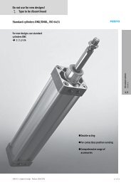
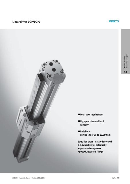
Linear drives <strong>DGP</strong>Peripherals overviewVariants and accessoriesType Brief description Page1 Linear drive<strong>DGP</strong>2 Load inverterAK3 Moment compensatorFK4 Slot coverB/S5 Proximity sensorG/H/I/J/N6 Plug socket with cableV7 Slot nut for profile slotY8 Central supportM9 Foot mountingFPneumatic linear drive with driver 1 / 3.1-66The driver should be mounted pointing downwards with long strokes > 2morin 1 / 3.1-119unfavourable environments. By using the load inverter it means that the load can beattached from above.For compensating misalignments when using external guides 1 / 3.1-120For protecting against dirt and securing proximity sensor cables 1 / 3.1-123Forsensingthedriverposition 1 / 3.1-125For proximity sensors 1 / 3.1-125For mounting attachments 1 / 3.1-123For mounting the axis, particularly with long strokes 1 / 3.1-117For mounting the axis 1 / 3.1-116<strong>Rodless</strong> cylindersMechanically coupled3.12005/04 – Subject to change – Products 2004/2005 1 / 3.1-65
Linear drives <strong>DGP</strong>Type code +ZUB – 2S2B F 2H 2VAccessoriesZUBAccessories supplied looseSlot cover…S…BSensor slotMounting slotSlot nut…Y For profile barrelCentral support…M Central supportFoot mounting…F Foot mountingProximity sensor…G With cable, 2.5 m…H With plug…I Contactless, with cable, 2.5 m…J Contactless, plug…N NC contact with cable, 2.5 m<strong>Rodless</strong> cylindersMechanically coupled3.1Plug socket…VWith cable, 2.5 m2005/04 – Subject to change – Products 2004/2005 1 / 3.1-67
Linear drives <strong>DGP</strong>Technical dataFunction-W- www.festo.com/en/Spare_parts_service-N- Diameter18 … 80 mm-T- Stroke length1 … 3000 mmWearing parts kits 1 / 3.1-78<strong>Rodless</strong> cylindersMechanically coupled3.1General technical dataPiston ∅ 18 25 32 40 50 63 80Constructional designPneumatic linear drive with driverProtection against torsion/guideSlotted profile barrelMode of operationDouble-actingDriver principlePositive-locking (slot)Mounting positionAnyPneumatic connection M5 G G G GStroke length [mm] 10 … 1800 10 … 3000 1)Cushioning (PPV)Adjustable at both endsCushioning length [mm] 16 18 20 30 83Position sensingVia magnet1) With effective strokes of over 2000 mm the installation of the drive unit must be with the sealing strip facing down; longer strokes available on request.Operating and environmental conditionsPiston ∅ 18 25 32 40 50 63 80Operating mediumFiltered compressed air, lubricated or unlubricatedOperating pressure [bar] 2…8 1.5 … 8Ambient temperature 1) [°C] –10 … +601) Note operating range of proximity sensors.Forces [N] and impact energy [Nm]Piston ∅ 18 25 32 40 50 63 80Theoretical force at 6 bar 153 295 483 754 1178 1870 3016Impact energy 1 / 3.1-71Weights [kg]Piston ∅ 18 25 32 40 50 63 80Basic weight with 0 mm stroke 0.46 0.84 1.55 2.65 5.88 9.1 17.3Additional weight per 10 mm stroke 0.016 0.036 0.041 0.057 0.111 0.148 0.158Moving load 0.08 0.18 0.32 0.55 1.55 1.76 5.01 / 3.1-68Products 2004/2005 – Subject to change – 2005/04
Linear drives <strong>DGP</strong>Technical dataMaterialsSectional view1 2 34Axis 18 25 32 40 50 63 801 End cap Anodised aluminium2 Profile Anodised aluminium3 Cover strip Corrosion resistant steel Polyurethane4 Driver Anodised aluminium– Seals Nitrile rubber, polyurethane<strong>Rodless</strong> cylindersMechanically coupled3.12005/04 – Subject to change – Products 2004/2005 1 / 3.1-69
Linear drives <strong>DGP</strong>Technical dataDimensionsStandard driver GKDownload CAD data www.festo.com/en/engineeringPiston ∅ 18<strong>Rodless</strong> cylindersMechanically coupledProfile barrel3.11 Supply ports at one end, optionof three sides of an end cap(D2variant:supplyportatbothends, option of three sides perend cap)2 Sensor slot for proximitysensor3 Mounting hole for footmounting HP4 Regulating screw for adjustableend-position cushioning+ = plus stroke lengthExtended driver GVPiston ∅ 18+ = plus stroke length1 / 3.1-72Products 2004/2005 – Subject to change – 2005/04
Linear drives <strong>DGP</strong>Technical dataDimensionsStandard driver GKDownload CAD data www.festo.com/en/engineeringPiston ∅ 80 Piston ∅ 32 … 63<strong>Rodless</strong> cylindersMechanically coupled3.11 Supply ports at one end, optionof three sides of an end cap(D2variant:supplyportatbothends, option of three sides perend cap)3 Mounting hole for footmounting HP4 Regulating screw for adjustableend-position cushioning+ = plus stroke lengthExtended driver GVPiston ∅ 32 … 63+ = plus stroke length1 / 3.1-74Products 2004/2005 – Subject to change – 2005/04
Linear drives <strong>DGP</strong>Technical dataProfile barrelPiston ∅ 32 Piston ∅ 40 Piston ∅ 50 Piston ∅ 63 Piston ∅ 80 2 Sensor slot for proximitysensor6 Sensor slot for slot nut NST∅ B1 B2 B3 B4 B5 B6 B11 D2 D3 D4 D5 D6 EE H1 H2∅ ∅ ∅[mm] ±0.2 ±0.2 H1032 54 35.8 19 46 21 40 9.5 4.3 5.2 M5 8 M5 G 72 6640 64 45.7 21 53 28 496.5 M6 10G 86 7850 90 69.2 24 76 44 72 12 6.3 8.5 M8 12 M6 G 115 10663 106 84.8 89 83M8 G 131 12280 130 102.5 36 – – – – – 12.2 M12 20 – G 174 158<strong>Rodless</strong> cylindersMechanically coupled3.1∅ H3 H4 H5 H6 J1 J2 J3 J4 L1 L2 L3 L4 L5 L6[mm] +0.9/–0.2 +0.3/–0.632 62 23 27 5.8 19 4.2 14 4.7 250 125 17 8.5 31 13540 71.8 26.5 32 7.7 22 5 21 9.1 300 150 11.5 11.517150 99 36 45 9.7 31.8 6.8 29.3 6 350 175 14 14 34 20663 115 44.5 5336 8 31 14 400 20023480 140.5 51 65 –33.3 3.6 520 260 19 19 45 334∅ L7 L8 L9 L10 L11 L12 L13 L14 L15 L16 L22 T1 T2 T3[mm] ±0.15 +0.9/–0.2 +0.3/–0.6 ±0.1 ±0.1 ±0.1 ±0.132 50 ±0.1 100 ±0.1 30 ±0.1 – 380 190 180 – 160 230 265 13.2 3 7.540 70 ±0.1 130 ±0.1 40 ±0.1 470 235 160 250 220 – 3414 10.550 80 ±0.1 150 ±0.1 50 ±0.1 550 275 280 – 250 350 406 15.2 6 12.563 110 ±0.1 190 ±0.1 70 ±0.1 650 325 380 310 430 484 21.280 180 ±0.15 230 ±0.15 115 ±0.15 60 – – – – – – – – 192005/04 – Subject to change – Products 2004/2005 1 / 3.1-75
Linear drives <strong>DGP</strong>Ordering data – Modular productsMMandatory dataOOptions<strong>Rodless</strong> cylindersMechanically coupled3.1Module No.175 133175 134175 135175 136175 137175 138175 139Drivefunction<strong>DGP</strong> 1825324050638010 … 3000PositionsensingPPV A B KVKHSize Stroke CushioningGenerationClampingunitBasicdesignGKGVSupplyport/driverD2FKAKOrderingexample175 134 <strong>DGP</strong> – 25 – 500 – PPV – A – B – KH – GV – D2 –Ordering tableSize 18 25 32 40 50 63 80 ConditionsM Module No. 175 133 175 134 175 135 175 136 175 137 175 138 175 139CodeSpecialmaterialsCTDrive function Pneumatic linear drive <strong>DGP</strong> <strong>DGP</strong>Size 18 25 32 40 50 63 80 -…Stroke [mm] 10 … 1800 10 … 3000 1 -…Cushioning Pneumatic cushioning adjustable at both ends -PPVPosition sensing Via magnet -A -AGeneration Bseries -B -BO Clamping unit Front – – – 2 -KVRear – – – 2 -KHBasic design Standard piston/slide -GKExtended piston/slide – -GVSupply port At both ends -D2Driver Moment compensator, assembled for <strong>DGP</strong> (FKP) 2 -FKLoad inverter – -AK Special materials Free of copper, PTFE and silicone -CTEntercode1 Stroke With piston diameter 18 and piston/slide extended (-GV):Restricted stroke 10 … 1750 mm2 KV, KH, FK Not with special material CT.Transfer order code<strong>DGP</strong> – – – – A – B – – –1 / 3.1-80Products 2004/2005 – Subject to change – 2005/04
Linear drives <strong>DGP</strong>Ordering data – Modular productsOOptionsAccessories Slot cover Slot nut Central support Foot mounting Proximity sensor Plug socketZUB…S…B…Y …M …F …G…H…I…J…N…V– ZUB – 10S F 2H 2VOrdering tableSize 18 25 32 40 50 63 80 ConditionsCodeEntercode<strong>Rodless</strong> cylindersMechanically coupled Accessories Supplied separately :ZUB- :ZUB-Slot cover, Sensor slot 1…10 …S2pcs.,0.5m Mounting1…10 …B– –slotSlot nut Profile – – 1…10 …YbarrelCentral support 1…10 …MFoot mounting 1…10 …FProximitysensor,magneticwithcable,2.5 m1…10(SME-8-K-LED-24)with plug 1…10(SME-8-S-LED-24)Proximity with 1…10sensor, cable, (SMT-8-PS-K-LED-24)magnetic,2.5 mcontactless with plug 1…10(SMT-8-PS-S-LED-24)Proximitysensor,magneticPlug socketNC contactwith cable,2.5 mwithcable,2.5 m1…10(SME-8-O-K-LED-24)1…10(SIM-M8-3GD-2,5-PU)…G…H…I…J…N…V3.1Transfer order code– : ZUB –2005/04 – Subject to change – Products 2004/2005 1 / 3.1-81
Linear drives <strong>DGP</strong>L, with guidePeripherals overview12345<strong>Rodless</strong> cylindersMechanically coupled3.16789aJaA1 / 3.1-82Products 2004/2005 – Subject to change – 2005/04
Linear drives <strong>DGP</strong>L, with guideType code +ZUB – 2S – – – F 2H 2V 2CAccessoriesZUBAccessories supplied looseSlot cover…S…BSensor slotMounting slotSlot nut…Y For mounting slot…X For slideCentring sleeve…Z For slideCentral support…M Central supportCentral mounting…Q Central mounting<strong>Rodless</strong> cylindersMechanically coupled3.1Foot mounting…FFoot mountingProximity sensor…G…H…I…J…NWith cable, 2.5 mWith plugContactless with cable, 2.5 mContactless, plugNC contact with cable, 2.5 mPlug socket…VWith cable, 2.5 mShock absorber kit…C…EPlus retainer for GK/GVFor GA2005/04 – Subject to change – Products 2004/2005 1 / 3.1-85
Linear drives <strong>DGP</strong>L, with guideTechnical dataWeights [kg]Piston ∅ 18 25 32 40 50 63 80Basic weight with 0 mm stroke GF 0.75 1.37 2.39 3.89 8.6 13.54 25.4KF 0.83 1.52 2.72 4.48 9.6 15.37 28.7GA – 1.69 – – –Additional weight per 10 mm stroke GF 0.022 0.042 0.051 0.072 0.132 0.181 0.202KF 0.026 0.053 0.069 0.097 0.167 0.236 0.270GA – 26 – – –Moving load GF 0.23 0.37 0.53 0.96 1.77 2.79 7.10KF 0.29 0.43 0.58 1.15 1.96 3.22 7.50GA – 0.91 – – –MaterialsSectional view1 2 34<strong>Rodless</strong> cylindersMechanically coupled3.1Axis 18 25 32 40 50 63 801 End cap Anodised aluminium2 Profile Anodised aluminium3 Cover strip Corrosion resistant steel Polyurethane4 Driver Anodised aluminium– Slide Anodised aluminium– Guide rail GF Anodised aluminiumKF Steel Corrosion resistant steel– Seals Nitrile rubber, polyurethane2005/04 – Subject to change – Products 2004/2005 1 / 3.1-87
Linear drives <strong>DGP</strong>L, with guideTechnical dataCharacteristic load values for drive with plain-bearing guide GFThe indicated forces and torquesrefer to the centre of the guide rail.They must not be exceeded in thedynamic range. Special attentionmust be paid to the cushioningphase.<strong>Rodless</strong> cylindersMechanically coupled3.1If the drive is subjected to more thantwo of the indicated forces andtorques simultaneously, thefollowing equations must be satisfiedin addition to the indicatedmaximum loads:Fy+Fz +Mx +My +Mz ≤ 1Fy max. Fz max. Mx max. My max. Mz max.-H- NoteAll values for the GF version refer toa speed of 0.2 m/s.Permissible forces and torquesPiston ∅ 18 25 32 40 50 63 80Standard slide GKFy max. [N] 340 430 430 1010 1010 2000 2000Fz max. [N] 340 430 430 1010 1010 2000 2000Mx max. [Nm] 2.2 5.4 8.5 23 32 74 100My max. [Nm] 10 14 18 34 52 140 230Mz max. [Nm] 10 14 18 34 52 140 230Extended slide GVFy max. [N] 330 400 395 930 870 1780 –Fz max. [N] 330 400 395 930 870 1780 –Mx max. [Nm] 2 5 8 21 28 66 –My max. [Nm] 18 25 30 58 83 235 –Mz max. [Nm] 18 25 30 58 83 235 –ProDrive selection andordering aidwww.festo.com/en/engineering1 / 3.1-88Products 2004/2005 – Subject to change – 2005/04
Linear drives <strong>DGP</strong>L, with guideTechnical dataCharacteristic load values for axis with recirculating ball bearing guide KF or protected version GAThe indicated forces and torquesrefer to the centre of the guide rail.They must not be exceeded in thedynamic range. Special attentionmust be paid to the cushioningphase.If the drive is subjected to more thantwo of the indicated forces andtorques simultaneously, thefollowing equations must be satisfiedin addition to the indicatedmaximum loads:Fy+Fz +Mx +My +Mz ≤ 1Fy max. Fz max. Mx max. My max. Mz max.<strong>Rodless</strong> cylindersMechanically coupled3.1Permissible forces and torquesPiston ∅ 18 25 32 40 50 63 80Standard slide GKFy max. [N] 930 3080 3080 7300 7300 14050 14050Fz max. [N] 930 3080 3080 7300 7300 14050 14050Mx max. [Nm] 7 45 63 170 240 580 745My max. [Nm] 23 85 127 330 460 910 1545Mz max. [Nm] 23 85 127 330 460 910 1545Extended slide GVFy max. [N] 930 3080 3080 7300 7300 14050 –Fz max. [N] 930 3080 3080 7300 7300 14050 –Mx max. [Nm] 7 45 63 170 240 580 –My max. [Nm] 45 170 250 660 920 1820 –Mz max. [Nm] 45 170 250 660 920 1820 –-H- NoteThe values for standard slide GK andpiston ∅ 18 … 40 apply to variantGA.2005/04 – Subject to change – Products 2004/2005 1 / 3.1-89
Linear drives <strong>DGP</strong>L, with guideTechnical data – Plain-bearing guideMaximum permissible static and dynamic characteristic load valuesStandard slide and plain-bearing guide <strong>DGP</strong>L-...-GF-GK-SThe pneumatic linear drive withplain-bearing guide <strong>DGP</strong>L-...-GF isdesigned for a maximum speed of1 m/s. At higher speeds and verticalapplication, it is recommended thatpneumatic linear drives withrecirculating ball bearing guide<strong>DGP</strong>L-...-KF are used as analternative.Maximum permissible speed v as a function of the force F<strong>Rodless</strong> cylindersMechanically coupled3.1Fy,Fz [N]<strong>DGP</strong>L-80<strong>DGP</strong>L-63<strong>DGP</strong>L-50<strong>DGP</strong>L-40<strong>DGP</strong>L-32<strong>DGP</strong>L-25<strong>DGP</strong>L-18v[m/s]Maximum permissible speed v as a function of the permissible torque MMx,My, Mz [Nm]<strong>DGP</strong>L-80<strong>DGP</strong>L-63<strong>DGP</strong>L-80<strong>DGP</strong>L-63<strong>DGP</strong>L-50<strong>DGP</strong>L-40<strong>DGP</strong>L-50<strong>DGP</strong>L-40<strong>DGP</strong>L-32<strong>DGP</strong>L-25<strong>DGP</strong>L-18<strong>DGP</strong>L-32<strong>DGP</strong>L-25<strong>DGP</strong>L-18v[m/s]1 / 3.1-90Products 2004/2005 – Subject to change – 2005/04
Linear drives <strong>DGP</strong>L, with guideTechnical data – Plain-bearing guideMaximum permissible static and dynamic characteristic load valuesExtended slide and plain-bearing guide <strong>DGP</strong>L-...-GF-GV-SThe pneumatic linear drive withplain-bearing guide <strong>DGP</strong>L-...-GF isdesigned for a maximum speed of1 m/s. At higher speeds and verticalapplication, it is recommended thatpneumatic linear drives withrecirculating ball bearing guide<strong>DGP</strong>L-...-KF are used as analternative.Maximum permissible speed in m/s as a function of the force FFy,Fz [N]v[m/s]Maximum permissible speed in m/s as a function of the permissible torque MMx,My,Mz [Nm]<strong>Rodless</strong> cylindersMechanically coupled3.1v[m/s]2005/04 – Subject to change – Products 2004/2005 1 / 3.1-91
Linear drives <strong>DGP</strong>L, with guideTechnical dataOperating range of the integrated end-position cushioning PPVMaximum permissible speed v as a function of the moving load M-H- Notev max. for GFThe data applies to a horizontalmounting position, applied load ontop.<strong>Rodless</strong> cylindersMechanically coupledv[m/s]m=Appliedload+movingload 1 / 3.1-87The graph opposite refers to r max.3.1m[kg]Pneumatic linear drivesThe end-position cushioning must beadjusted to ensure jerk-freeoperation. If the operating conditionsareoutsidethepermissiblerange,theloadtobemovedmustbeexternally cushioned using suitableequipment (shock absorbers, stops,etc), preferably at the centre ofgravity of the mass.with slide <strong>DGP</strong>LLoadr max. =20mmfor piston ∅ 18 mmr max. =50mmfor piston ∅ 25 ... 80 mm(data for greater load distances onrequest)-H- NoteEvenness of applied loads onpneumatic linear drives with slide<strong>DGP</strong>L: To avoid distortion orloosening of the guide elements, thebearing surface of the assembly mustmaintain a flatness of at least0.03 mm.1 / 3.1-92Products 2004/2005 – Subject to change – 2005/04
Linear drives <strong>DGP</strong>L, with guideTechnical dataMaximum permissible support span l as a function of the force FThe axis may need to be supportedwith central supports MUP in order torestrict deflection with long strokelengths. The following diagrams serveto determine the maximumpermissible support span l as afunction of the force F acting uponthe axis.Force on the surface of the slideFFFPiston ∅ 18 … 40<strong>Rodless</strong> cylindersMechanically coupled3.1F[N]<strong>DGP</strong>...-40<strong>DGP</strong>...-32<strong>DGP</strong>...-25<strong>DGP</strong>...-18l [mm]Piston ∅ 50 … 80F[N]<strong>DGP</strong>...-80<strong>DGP</strong>...-63<strong>DGP</strong>...-50l [mm]2005/04 – Subject to change – Products 2004/2005 1 / 3.1-93
Linear drives <strong>DGP</strong>L, with guideTechnical dataDimensionsStandard slide GKPiston ∅ 18Download CAD data www.festo.com/en/engineering5 Holes for centring pinZBS 5+ = plus stroke lengthBasic dimensions 1 / 3.1-72<strong>Rodless</strong> cylindersMechanically coupled3.1Extended slide GVPiston ∅ 18Protected version GAPiston ∅ 181 / 3.1-94Products 2004/2005 – Subject to change – 2005/04
Linear drives <strong>DGP</strong>L, with guideTechnical dataDimensionsStandard slide GKPiston ∅ 25Download CAD data www.festo.com/en/engineering5 Hole for centring sleeve ZBH-96 Mounting slot for slot nutNSTL-257 Hole for central mounting SLZZ+ = plus stroke lengthBasic dimensions1 / 3.1-73<strong>Rodless</strong> cylindersMechanically coupled3.1Extended slide GVPiston ∅ 25Protected version GAPiston ∅ 25 … 402005/04 – Subject to change – Products 2004/2005 1 / 3.1-95
Linear drives <strong>DGP</strong>L, with guideTechnical dataDimensionsStandard slide GKPiston ∅ 32 … 80Download CAD data www.festo.com/en/engineering5 Hole for centring sleeve ZBH-96 Mounting slot for slot nut NSTL7 Hole for central mounting SLZZ+ = plus stroke length<strong>Rodless</strong> cylindersMechanically coupledBasic dimensions1 / 3.1-743.1Extended slide GVPiston ∅ 32 … 63Protected version GAPiston ∅ 32 … 401 / 3.1-96Products 2004/2005 – Subject to change – 2005/04
Linear drives <strong>DGP</strong>L, with guideTechnical data∅ B3 B7 B8 B9 B10 B11 B12 B14 D1 EE[mm] +0.2 ±0.0332 19 63 79 47 ±0.15 20 9.5 112.1 67.6 – G40 21 78.5 96.5 55 ±0.2137.6 79.6 M5 G50 24 97 122 72 ±0.2 40 12 – – –63 121 142 90 ±0.25 G80 36 151.5 188 112 +0.5/–0.2 – G∅ H1 H5 H7 H8 H10 H11 H12 H13 L1 L2[mm] +0.9/–0.2 +0.3/–0.632 72 27 77.5 18.5 93.1 – 49.5 34.1 250 12540 86 32 90.5 20 106.6 23.1 54 36.1 300 15050 115 45 122.5 26 – – – – 350 17563 131 53 144.5 30 400 20080 174 65 175 36.5 520 260<strong>Rodless</strong> cylindersMechanically coupled3.1∅ L17 L18 L19 L20 L21 L23 L24 L25 T4 T5[mm] ±0.03 ±0.03 ±0.1 max.32 131 +0.2 40 – 261 40 131 – – 12.5 –40 167 +0.2 40 337 167 150 58750 202 +0.2 402 80 – – – 18.5 –63 230 +0.2 480 120 20.580 320 –0.3 – – 272005/04 – Subject to change – Products 2004/2005 1 / 3.1-97
Linear drives <strong>DGP</strong>L, with guideTechnical data – Clamping unitClamping unit <strong>DGP</strong>L-…-KUThe clamping unit is clamped in theunpressurised state.<strong>Rodless</strong> cylindersMechanically coupledGeneral technical dataPiston ∅ 18 25 32 40Constructional designSpring actuated clamping profileStroke [mm] 10 … 1800 10 … 30003.1Operating and environmental conditionsPiston ∅ 18 25 32 40Operating pressure [bar] 4…8Grade of filtration [µm] 40Pneumatic connectionGAmbient temperature 1) [°C] –10 … +601) Note for proximity sensors.Clamping unit weights [kg]Piston ∅ 18 25 32 40Basic weight with 0 mm stroke 0.388 0.649 0.985 1446Additional weight per 10 mm stroke 0.018 0.026 0.034 0.041Moving load with 0 mm stroke 0.061 0.120 0.153 0.213MaterialsSectional view1 2 3Clamping unit1 Housing Anodised aluminium2 Clamping profile Anodised aluminium3 Driver Anodised aluminium– Cover Acrylic butadiene styrene– Seals Polyurethane1 / 3.1-98Products 2004/2005 – Subject to change – 2005/04
Linear drives <strong>DGP</strong>L, with guideTechnical data – Clamping unitClamping unit DG…-…-K…Holding force FH of the clamping unit dependent on the stroke l-H- NoteFH [N]Environmental conditions:Clamping surfaces oil, grease anddirt-freel [mm]<strong>Rodless</strong> cylindersMechanically coupledDimensionsDownload CAD data www.festo.com/en/engineering3.1+ = plus stroke length-H- NoteClamping units <strong>DGP</strong>…-…-K… have asupplyportatoneendonly.For ∅ B1 B2 B3 B4 D1 H1 H2 H3 H4 H5 H6 L1 L2 L3 L4 L5 L6[mm] max. max. max. max. ±0.118 – 31.2 17.2 81 G57 56.7 28.5 0.5 8.2 – 176 85 32 25 16.5 9.525 33.3 19.3 96.3 68.5 67.8 32.7 0.6 5.9 – 207 1057 –32 32.7 17.7 104.7 77.5 76.8 41 1 5.9 – 251 131 31 140 37.1 23.1 123.1 90.5 90 54.6 1.7 5.4 – 301 1672005/04 – Subject to change – Products 2004/2005 1 / 3.1-99
Linear drives <strong>DGP</strong>L, with guideOrdering data<strong>Rodless</strong> cylindersMechanically coupled3.1Ordering data – Standard strokePiston ∅ Part No. Type25 526 649 <strong>DGP</strong>L-25-250-PPV-A-B-KF526 650 <strong>DGP</strong>L-25-400-PPV-A-B-KF526 651 <strong>DGP</strong>L-25-500-PPV-A-B-KF526 652 <strong>DGP</strong>L-25-1000-PPV-A-B-KF32 526 657 <strong>DGP</strong>L-32-250-PPV-A-B-KF526 658 <strong>DGP</strong>L-32-400-PPV-A-B-KF526 659 <strong>DGP</strong>L-32-500-PPV-A-B-KF526 660 <strong>DGP</strong>L-32-1000-PPV-A-B-KF40 526 665 <strong>DGP</strong>L-40-250-PPV-A-B-KF526 666 <strong>DGP</strong>L-40-400-PPV-A-B-KF526 667 <strong>DGP</strong>L-40-500-PPV-A-B-KF526 668 <strong>DGP</strong>L-40-1000-PPV-A-B-KFOrdering data – Variable stroke for plain-bearing guide GFPiston ∅ Part No. Type18 161 974 <strong>DGP</strong>L-18-…-PPV-A-GF-B25 161 786 <strong>DGP</strong>L-25-…-PPV-A-GF-B32 161 787 <strong>DGP</strong>L-32-…-PPV-A-GF-B40 161 788 <strong>DGP</strong>L-40-…-PPV-A-GF-B50 161 789 <strong>DGP</strong>L-50-…-PPV-A-GF-B63 161 790 <strong>DGP</strong>L-63-…-PPV-A-GF-B80 161 791 <strong>DGP</strong>L-80-…-PPV-A-GF-BOrdering data – Variable stroke for recirculating ball bearing guide KFPiston ∅ Part No. Type18 161 977 <strong>DGP</strong>L-18-…-PPV-A-KF-B25 161 792 <strong>DGP</strong>L-25-…-PPV-A-KF-B32 161 793 <strong>DGP</strong>L-32-…-PPV-A-KF-B40 161 794 <strong>DGP</strong>L-40-…-PPV-A-KF-B50 161 795 <strong>DGP</strong>L-50-…-PPV-A-KF-B63 161 796 <strong>DGP</strong>L-63-…-PPV-A-KF-B80 161 797 <strong>DGP</strong>L-80-…-PPV-A-KF-BOrdering data – Wearing parts kitsPiston ∅ Part No. Type18 384 266 <strong>DGP</strong>L-18-…-PPV-A25 123 563 <strong>DGP</strong>L-25-…-PPV-A32 123 564 <strong>DGP</strong>L-32-…-PPV-A40 123 565 <strong>DGP</strong>L-40-…-PPV-A50 123 566 <strong>DGP</strong>L-50-…-PPV-A63 123 567 <strong>DGP</strong>L-63-…-PPV-A80 123 568 <strong>DGP</strong>L-80-…-PPV-A-H- NotePiston ∅ 8and12Linear drives DGC 1/3.1-2Core Range1 / 3.1-100Products 2004/2005 – Subject to change – 2005/04
Linear drives <strong>DGP</strong>L, with guideOrdering data – Modular productsOrder codeMandatory dataGKStandard slideD2Supply portGVExtended slideKUClamping unit underneathSHSVSlide at rearSlide at frontCTFree of copper, PTFE andsiliconeStandard slide GKExtended slide GVClamping unit KU<strong>Rodless</strong> cylindersMechanically coupledSV3.1-H--H--H- NoteThe insertion point for the proximitysensor is located on the right-handside of the pneumatic linear drive<strong>DGP</strong>L.OURLVHtopunderneathrightleftfrontrearOptionsC/EXQZB/SG/H/I/J/NVYMF2005/04 – Subject to change – Products 2004/2005 1 / 3.1-101
Linear drives <strong>DGP</strong>L, with guideOrdering data – Modular productsMMandatory dataOOptions<strong>Rodless</strong> cylindersMechanically coupled3.1Module No.175 133175 134175 135175 136175 137175 138175 139Drivefunction<strong>DGP</strong>L 1825324050638010 … 3000 PPPVPositionsensingGuideA B GFKFSize Stroke CushioningGenerationClampingunitKUBasicdesignGKGVSlideattachmentpositionSVSHOrderingexample175 138 <strong>DGP</strong>L – 63 – 800 – PPV – A – B – KF – – GK – SH – D2 –SupplyportD2Ordering tableSize 18 25 32 40 50 63 80 ConditionsM Module No. 175 133 175 134 175 135 175 136 175 137 175 138 175 139Drive function Pneumatic linear drive <strong>DGP</strong>L <strong>DGP</strong>LSize 18 25 32 40 50 63 80 -…Stroke [mm] 10 … 1800 10 … 3000 1 -…Cushioning Pneumatic cushioning adjustable at both ends -PPVPosition sensing Via magnet -A -AGeneration Bseries -B -BGuide Plain-bearing guide -GFRecirculating ball bearing guide-KFO Clamping unit Underneath – – – 2 -KUBasic design Standard piston/slide -GKExtended piston/slide – 2 -GVSlide attachment position At rear -SHAt front-SV Supply port At both ends -D2CodeEntercode1 Stroke With piston diameter 18 and piston/slide extended (-GV):Restricted stroke 10 … 1750 mm2 KU, GV Not with protected version GA and special material CT.Transfer order code<strong>DGP</strong>L – – – – A – B – – – – – –1 / 3.1-102Products 2004/2005 – Subject to change – 2005/04
Linear drives <strong>DGP</strong>L, with guideOrdering data – Modular productsOOptionsSpecialmaterialsProtectedversionAccessoriesSlotcoverSlot nutCentringsleeveCentralsupportCentralmountingFootmountingProximitysensorPlugsocketShockabsorberkitCT GA ZUB …S…B…X…Y…Z …M …Q …F …G…H…I…J…N…V…C…E<strong>Rodless</strong> cylindersMechanically coupled– CT – : ZUB – 2S2B 5Y2X 20Z Q F 2G 2C3.1Ordering tableSize 18 25 32 40 50 63 80 ConditionsCodeEntercode Special materials Free of copper, PTFE and silicone -CTO Protected version Protected roller bearing design for harsh environment – – – 3 -GAAccessories Supplied separately :ZUB- :ZUB-Slot cover, Sensor slot 1…10 …S2pcs.,0.5m Mounting1…10 …B– –slotSlot nut Slide – 1…10 …XMounting1…10 …Y– –slotCentring sleeve (pack of 10) 10, 20, 30, 40, 50, 60, 70, 80, 90…ZCentral support 1…10 …MCentral mounting – 1…10 …QFoot mounting 1…10 …FProximity with cable, 1…10…Gsensor,magnetic2.5 mwith plug(SME-8-K-LED-24)1…10…H(SME-8-S-LED-24)Proximity with cable, 1…10…Isensor,magnetic,contactless2.5 mwith plug(SMT-8-PS-K-LED-24)1…10(SMT-8-PS-S-LED-24)…JProximitysensor, magneticPlug socketNC contactwith cable,2.5 mwith cable,2.5 m1…10(SME-8-O-K-LED-24)1…10(SIM-M8-3GD-2,5-PU)Shock 1…10 …Cabsorber kit 1…10 – – – 4 …E…N…V3 GA Only with recirculating ball bearing guide KF. 4 E Only with protected version GA.Transfer order code– – : ZUB –2005/04 – Subject to change – Products 2004/2005 1 / 3.1-103
Linear drives <strong>DGP</strong>L-HD, with heavy-duty guidePeripherals overview1234<strong>Rodless</strong> cylindersMechanically coupled3.15567859aJ1 / 3.1-104Products 2004/2005 – Subject to change – 2005/04
Linear drives <strong>DGP</strong>L-HD, with heavy-duty guidePeripherals overviewVariants and accessoriesType Brief description Page1 Linear axisPneumatic linear drive with heavy-duty guide 1 / 3.1-106<strong>DGP</strong>L-HD2 Slot nut for slideFor mounting loads and attachments on the slide 1 / 3.1-124X3 Central mountingFor centring loads and attachments on the slide 1 / 3.1-124Q4 Shock absorber kitFor slowing higher speeds to a stop 1 / 3.1-122D5 Slot nut for side mounting slot Y For mounting attachments 1 / 3.1-1246 Slot coverFor protecting against ingress of dirt 1 / 3.1-124B/S7 Proximity sensorFor sensing the slide position 1 / 3.1-125G/H/I/J/N8 Plug socket with cableFor proximity sensors 1 / 3.1-125V5 Slot nut for mounting slot underneath U For mounting attachments 1 / 3.1-124<strong>Rodless</strong> cylindersMechanically coupled3.19 Central supportMaJ Foot mountingFFor mounting the axis 1 / 3.1-118For mounting the axis 1 / 3.1-1182005/04 – Subject to change – Products 2004/2005 1 / 3.1-105
Linear drives <strong>DGP</strong>-HD, with heavy-duty guideType code<strong>DGP</strong>L – 25 – 500 – PPV – A – B – GK – D2 – CTType<strong>DGP</strong>LLinear drive with heavy-duty guidePiston ∅Stroke [mm]<strong>Rodless</strong> cylindersMechanically coupled3.1CushioningPPV Adjustable end-position cushioningPosition sensingA Via magnetGenerationB BseriesBasic designGK Standard slideSupply portD2 SupplyportatbothendsSpecial materialsCT Free of copper, PTFE and silicone1 / 3.1-106Products 2004/2005 – Subject to change – 2005/04
Linear drives <strong>DGP</strong>-HD, with heavy-duty guideType code +ZUB – 2S – – F 2H 2V 2DAccessoriesZUBAccessories supplied looseSlot cover…S…BSensor slotMounting slotSlot nut…Y For side mounting slot…X For slide…U For mounting slot underneathCentral support…M Central supportCentral mounting…Q Central mounting<strong>Rodless</strong> cylindersMechanically coupled3.1Foot mounting…FFoot mountingProximity sensor…G…H…I…J…NWith cable, 2.5 mWith plugContactless with cable, 2.5 mContactless, plugNC contact with cable, 2.5 mPlug socket…VWith cable, 2.5 mShock absorber kit…DFor heavy-duty guide2005/04 – Subject to change – Products 2004/2005 1 / 3.1-107
Linear drives <strong>DGP</strong>L-HD, with heavy-duty guideTechnical dataFunction-W- www.festo.com/en/Spare_parts_service-N- Diameter18 … 80 mm-T- Stroke length10 … 2160 mmWearing parts kits 1 / 3.1-113<strong>Rodless</strong> cylindersMechanically coupled3.1General technical dataPiston ∅ 18-HD18 18-HD25 25-HD25 25-HD40 32-HD40 40-HD40Constructional designPneumatic linear drive with heavy-duty guideProtection against torsion/guideSlotted profile barrel/recirculating ball bearing guideMode of operationDouble-actingDriver principlePositive-locking (slot)Mounting positionAnyPneumatic connection M5 G GStroke length [mm] 10 … 1710 10 … 1640 10 … 2160 10 … 2110Cushioning PNon-adjustable at both endsSelf-adjusting at both endsCushioning length [mm] –Position sensingVia magnetMax. speed [m/s] 3Operating and environmental conditionsPiston ∅ 18-HD18 18-HD25 25-HD25 25-HD40 32-HD40 40-HD40Operating mediumFiltered compressed air, lubricated or unlubricatedOperating pressure [bar] 2…8 1.5 … 8Ambient temperature 1) [°C] –10 … +601) Note operating range of proximity sensors.Forces [N]Piston ∅ 18-HD18 18-HD25 25-HD25 25-HD40 32-HD40 40-HD40Theoretical force at 6 bar 153 295 483 754Weights [kg]Piston ∅ 18-HD18 18-HD25 25-HD25 25-HD40 32-HD40 40-HD40Basic weight with 0 mm stroke 3.7 4.4 5.1 13.9 14.4 15.4Additional weight per 10 mm stroke 0.089 0.133 0.152 0.212 0.217 0.233Moving load 0.530 1.86 1.96 3.48 3.615 3.8501 / 3.1-108Products 2004/2005 – Subject to change – 2005/04
Linear drives <strong>DGP</strong>L-HD, with heavy-duty guideTechnical dataMaterialsSectional view2 41 3Axis1 Profile Anodised aluminium2 End cap Anodised aluminium3 Slide Anodised aluminium4 Guide rail Steel– Seals Nitrile rubber, polyurethane<strong>Rodless</strong> cylindersMechanically coupled3.1Characteristic load values for drive with heavy-duty guide HDThe indicated forces and torquesrefer to the centre of the heavy-dutyguide. They must not be exceeded inthe dynamic range. Special attentionmust be paid to the cushioningphase.If the drive is subjected to more thantwo of the indicated forces andtorques simultaneously, thefollowing equations must be satisfiedin addition to the indicatedmaximum loads:Fy+Fz +Mx +My +Mz ≤ 1Fy max. Fz max. Mx max. My max. Mz max.Permissible forces and torquesPiston ∅ HD-18 HD25 HD-40Fy max. [N] 1820 5400 5400Fz max. [N] 1820 5600 5600Mx max. [Nm] 70 260 375My max. [Nm] 115 415 560Mz max. [Nm] 112 400 5402005/04 – Subject to change – Products 2004/2005 1 / 3.1-109
Linear drives <strong>DGP</strong>L-HD, with heavy-duty guideTechnical dataMaximum permissible support span l as a function of the force FThe axis may need to be supportedwith central supports MUP in order torestrict deflection with long strokelengths. The following diagrams serveto determine the maximumpermissible support span l as afunction of the force F acting uponthe axis.Force on the surface of the slideFFFI [mm]F[kN]F[kN]<strong>Rodless</strong> cylindersMechanically coupled3.1l [mm]1 / 3.1-110Products 2004/2005 – Subject to change – 2005/04
Linear drives <strong>DGP</strong>L-HD, with heavy-duty guideTechnical dataDimensionsDownload CAD data www.festo.com/en/engineering1 Mounting slot for slot nut NSTH2 Mounting slot for slot nut NST3 Sensor slot for proximitysensor4 Central mounting SLZZ5 Slot nut NSTH6 Thread for shock absorber YHDor YSR-…-C7 Thread for threaded pin (shockabsorber kit)8 Rubber buffer9 Supplyportatoneend(D2variant:supplyportatbothends)+ = plus stroke length<strong>Rodless</strong> cylindersMechanically coupledProfile3.1Heavy-duty y B1 B2 B3 B4 B5 D1 D2 D3 D4 D5 H1 H2 H3 H4guide∅[mm] ±0.2 G718-HD18 80 ±0.3 85 116 40 36 M5 M12x1 25 M6 M5 70 12.8 19.5 ±0.1 1518-HD25 100 ±0.3 114 144 48 56 ±0.5 M8 M16x1M8 G 93.5 18.5 25 ±0.2 2225-HD2525-HD40 140 ±0.355 156 185 54 68 M22x1.5 124.5 21 48 ±0.2 3632-HD4040-HD40GHeavy-duty y H5 H6 H7 H8 H9 H10 H11 H12 L1 L2 L4 L5 L8 T1guide[mm]18-HD18 43.3 5.9 8.7 20x45° 68 0.8 25.5 49 240 120 15 25 160 3.518-HD25 53.8 9 9.8 30x45° 90 2 33 63 310 15535 21025-HD2525-HD40 83.8 5.5 5 15.5 5 34x45° 120 59 89 354 177 32 260 432-HD4054.440-HD40 47.52005/04 – Subject to change – Products 2004/2005 1 / 3.1-111
Linear drives <strong>DGP</strong>L-HD, with heavy-duty guideOrdering data – Modular productsOrder codeMandatory dataGKD2CTStandard slideSupply portFree of copper, PTFE andsiliconeWith heavy-duty guide HD<strong>Rodless</strong> cylindersMechanically coupled3.1-H- NoteThe insertion point for the proximitysensor is located at the left-hand sideof the heavy-duty guideOURLVHtopunderneathrightleftfrontrearOrdering data – Wearing parts kitsPiston ∅ Part No. Type18 384 266 <strong>DGP</strong>-18-…-PPV-A25 123 563 <strong>DGP</strong>-25-…-PPV-A32 123 564 <strong>DGP</strong>-32-…-PPV-A40 123 565 <strong>DGP</strong>-40-…-PPV-A50 123 566 <strong>DGP</strong>-50-…-PPV-A63 123 567 <strong>DGP</strong>-63-…-PPV-A80 123 568 <strong>DGP</strong>-80-…-PPV-A1 / 3.1-112Products 2004/2005 – Subject to change – 2005/04
Linear drives <strong>DGP</strong>L-HD, with heavy-duty guideOrdering data – Modular productsOrder codeOptionsXQD<strong>Rodless</strong> cylindersMechanically coupled3.1YB/SG/H/I/J/NVUMF2005/04 – Subject to change – Products 2004/2005 1 / 3.1-113
Linear drives <strong>DGP</strong>L-HD, with heavy-duty guideOrdering data – Modular productsMMandatory dataOOptionsModule No.DrivefunctionSize Stroke Cushioning PositionsensingGuide Basic design Supply port175 133175 134175 135<strong>DGP</strong>L 18253210 … 2160 PPV A HD18HD25HD40GKD2175 13640<strong>Rodless</strong> cylindersMechanically coupled3.1Orderingexample175 134 <strong>DGP</strong>L – 25 – 800 – PPV – A – HD25 – GK – D2 –Ordering tableSize 18 25 32 40 ConditionsCodeEntercodeM Module No. 175 133 175 134 175 135 175 136Drive function Pneumatic linear drive with heavy-duty guide <strong>DGP</strong>L <strong>DGP</strong>LSize 18 25 32 40 -…Stroke [mm] HD18 10 … 1710 – – – -…HD25 10 … 1650 10 … 2160 – – -…HD40 – 10 … 2110 -…Cushioning Pneumatic cushioning adjustable at both ends -PPV -PPVPosition sensing Via magnet -A -AGuide Heavy-duty y HD18 – – – -HD18guide HD HD25 – – -HD25– HD40 -HD40O Basic design Standard piston/slide -GK Supply port At both ends -D2Transfer order code<strong>DGP</strong>L – – – PPV – A – – – –1 / 3.1-114Products 2004/2005 – Subject to change – 2005/04
Linear drives <strong>DGP</strong>L-HD, with heavy-duty guideOrdering data – Modular productsOOptionsSpecialmaterialsAccessoriesCT ZUB …S…BSlot cover Slot nut Centralsupport…X…Y…UCentralmountingFootmounting…M …Q …F …G…H…I…J…NProximitysensor,magneticPlug socket…VShockabsorber kit…D– CT : ZUB – 2S2B 2X5Y5U 2Q F 2G 2DOrdering tableSize 18 25 32 40 Conditions Special materials Free of copper, PTFE and silicone -CTO Accessories Supplied separately :ZUB- :ZUB-Slot cover, Sensor slot 1…10…S2pcs.,0.5mMountingslot1…10 …BSlot nut Slide 1…10 …XMounting 1…10 …YslotMountingslot underneath1…10 …UCentral support 1…10 …MCentral mounting 1…10 …QFoot mounting 1…10 …FProximitysensor,magneticwithcable,2.5 m1…10(SME-8-K-LED-24)with plug 1…10(SME-8-S-LED-24)Proximity with 1…10sensor, cable, (SMT-8-PS-K-LED-24)magnetic,2.5 mcontactless with plug 1…10(SMT-8-PS-S-LED-24)Proximitysensor,magneticPlug socketNC contactwith cable,2.5 mwithcable,2.5 m1…10(SME-8-O-K-LED-24)1…10(SIM-M8-3GD-2,5-PU)Shock absorber kit 1…10 …DCode…G…H…I…J…N…VEntercode<strong>Rodless</strong> cylindersMechanically coupled3.1Transfer order code– : ZUB –2005/04 – Subject to change – Products 2004/2005 1 / 3.1-115
Linear drives <strong>DGP</strong>/<strong>DGP</strong>LAccessoriesFoot mounting HP(order code F)Material:Galvanised steelFree of copper, PTFE and siliconePiston ∅ 18<strong>Rodless</strong> cylindersMechanically coupledPiston ∅ 25-…-803.1HP-25+ = plus stroke lengthDimensions and ordering dataFor ∅ AB AH AO AT AU SA TR Weight Part No. Type∅ GK GV[mm][g]18 5.5 24 4.8 3 13.2 176.5 256.4 24 59 158 472 HP-1825 5.5 29.5 6 3 13 226 326 32.5 61 150 731 HP-2532 6.6 37 7 4 17 284 414 38 117 150 732 HP-3240 6.6 46 8.5 5 17.5 335 505 45 188 150 733 HP-4050 9 61 11 6 25 400 600 65 243 150 734 HP-5063 11 69 13.5 6 28 456 706 75 305 150 735 HP-6380 13 85 12 8 28 576 – 72 620 158 453 HP-80Core Range1 / 3.1-116Products 2004/2005 – Subject to change – 2005/04
Linear drives <strong>DGP</strong>/<strong>DGP</strong>LAccessoriesCentral support MUP(order code M)Material:Galvanised steelFree of copper, PTFE and siliconePiston ∅ 18 and 25 Piston ∅ 32 … 631 Position of the central supportalong the profile barrel is freelyselectable<strong>Rodless</strong> cylindersMechanically coupledMUP-40Dimensions and ordering dataFor ∅ AH B1 B2 D1 H1 H2 L1 L2 L3 Weight Part No. Type∅[mm][g]18 24 70.5 47 5.5 13 7 25 – – 29 150 736 MUP-18/2525 29.5 81 58 5.5 13 7 25 – – 33 150 736 MUP-18/2532 37 35 22 6.6 – – – 41.5 35 89 150 737 MUP-3240 46 35 22 6.6 – – – 47 40 126 150 738 MUP-4050 61 50 26 11 – – – 70 58 241 150 739 MUP-5063 69 50 26 11 – – – 77 65 340 150 800 MUP-6380 85 50 26 11 – – – 88 76 590 158 455 MUP-803.1Core Range2005/04 – Subject to change – Products 2004/2005 1 / 3.1-117
Linear drives <strong>DGP</strong>/<strong>DGP</strong>LAccessoriesFoot mounting HHPfor heavy-duty guide(order code F)Material:Galvanised steel<strong>DGP</strong>L-…-HD18/-HD25/-HD40<strong>Rodless</strong> cylindersMechanically coupled3.1Central support MUPfor heavy-duty guide(order code M)Material:Galvanised steelFree of copper, PTFE and silicone1 Foot mounting HHP2 Central support MUP+ = plus stroke lengthDimensions and ordering dataFor heavy-dutyguide[mm]HD18B1 B4 B5 B6 C1 D1∅D2∅D4∅H1 H2 H380 40 22 35 34 5.5 6.6 6.6 8 14 26.8HD25HD40100 50 26 50 50 9 11 11 8 16 34.5140 70 26 50 50 9 11 11 10 16 37For heavy-dutyguide[mm]HD18HD25HD40L8 L9 L10 L11 L12 L13 L14 Weight Part No. Type[g]68 75 64 92 99 9 290357 161 993 HHP-18126 150 738 MUP-4088 100 90 128 140 15 380794 161 994 HHP-25347 150 739 MUP-50108 120 110 148 160 15 4241318 161 995 HHP-40347 150 739 MUP-50Core Range1 / 3.1-118Products 2004/2005 – Subject to change – 2005/04
Linear drives <strong>DGP</strong>/<strong>DGP</strong>LAccessoriesLoad inverter AKfor <strong>DGP</strong>(order code AK)Material:Galvanised steel<strong>Rodless</strong> cylindersMechanically coupled3.11 Screw DIN 912Dimensions and ordering dataFor ∅ B1 B2 D1 H1 H2 H3 H4 L1 L2[mm]18 29 23 M5 62.7 35.8 3 5 79.6 –25 39 29.5 M5 76.1 43.5 3 5 105 –32 43.5 34 M5 87 49 4 6 131 10040 50.5 40 M6 104 58 4 8.1 167 13050 67 55 M8 138.5 75 5 10.5 202 15063 77 65 M8 156.5 84 6 11.5 230 190For ∅ L3 L4 L5 1 CRC 1) Weight Part No. Type[mm]18 60 60 20 M5x12 2 227 196 105 AK-1825 50 50 20 M5x10 380 196 106 AK-2532 30 100 30 M5x12 690 196 107 AK-3240 40 130 40 M6x14 1050 196 108 AK-4050 50 150 50 M8x16 2080 196 109 AK-5063 70 190 70 M8x18 2820 196 110 AK-63[g]1) Corrosion resistance class 2 according to Festo standard 940 070Components requiring moderate corrosion resistance. Externally visible parts with primarily decorative surface requirements which are in direct contact with a surrounding industrial atmosphere or media such ascooling or lubricating agents.2005/04 – Subject to change – Products 2004/2005 1 / 3.1-119
Linear drives <strong>DGP</strong>/<strong>DGP</strong>LAccessoriesMoment compensator FKPfor <strong>DGP</strong>(order code FK)Material:Galvanised steel<strong>Rodless</strong> cylindersMechanically coupled<strong>DGP</strong>-18<strong>DGP</strong>-25 … 803.1Dimensions and ordering dataFor ∅ B6 B7 B8 B9 D1 D4 D5 H2 H3 H4 L2 L10 L11 L12 Part No. Type∅ ∅[mm]18 – – 26 30 6 9 M4 43.8 3 57.8 75 40 70 20 158 474 FKP-1825 20 40 54 50 8 5.5 M5 57 5 75 100 66 80 – 150 801 FKP-25/3232 20 40 54 50 8 5.5 M5 66 5 84 125 66 80 – 150 801 FKP-25/3240 24 44 58 60 10 6.5 M6 78 6 99 150 76 90 – 150 802 FKP-4050 23 51 71 63 12 9 M8 106 8 130 175 102 122 – 150 803 FKP-50/6363 23 51 71 63 12 9 M8 122 8 146 200 102 122 – 150 803 FKP-50/6380 – – – 94 20 – – 158 13 194.5 258 – – – 158 457 FKP-80Core Range1 / 3.1-120Products 2004/2005 – Subject to change – 2005/04
Linear drives <strong>DGP</strong>/<strong>DGP</strong>LAccessoriesShock absorber YSR-…-Cfor <strong>DGP</strong>L(order code C)Material:Housing: galvanised steel; piston rod:high-alloy steel,seals: nitrile rubber, polyurethaneFree of copper, PTFE and silicone-H- NoteShock absorber YSRW withprogressive characteristics Volume 1Ordering dataFor ∅ Weight Part No. Type[mm] [g]18 50 34 571 YSR-8-8-C25 70 34 572 YSR-12-12-C32 70 34 572 YSR-12-12-C40 140 34 573 YSR-16-20-C50 140 34 573 YSR-16-20-C63 240 34 574 YSR-20-25-C80 240 34 574 YSR-20-25-C<strong>Rodless</strong> cylindersMechanically coupled3.1Shock absorber retainer KYPfor <strong>DGP</strong>L(order code C)Material:Retainer: AluminiumSleeve: Corrosion resistant steelShock absorber not included in scopeof delivery.1 Shock absorber retainer KYP(if the retainer is in contact withthe end cap, i.e. cap serves tosecure position, the entire strokelength can be utilised)2 Shock absorber YSR-...-C3 Position retainer(included in scope of delivery)either behind or underneath theshock absorber retainer KYPDimensions and ordering dataFor ∅ B8 D1 D5 H2 H4 Weight Part No. Type[g]18 14 M12x1 M4 50.5 4.5 65 158 907 KYP-1825 19 M16x1 M5 69.5 6 95 158 908 KYP-2532 25 M16x1 M5 80 8 130 158 909 KYP-3240 32 M22x1.5 M5 102 8 209 158 910 KYP-4050 35 M22x1.5 M8 124 10 415 158 911 KYP-5063 44 M26x1.5 M10 152.5 11.5 609 158 912 KYP-6380 44 M26x1.5 M10 179.5 11.5 774 158 913 KYP-80Core Range2005/04 – Subject to change – Products 2004/2005 1 / 3.1-121
Linear drives <strong>DGP</strong>/<strong>DGP</strong>LAccessoriesShock absorber DG-GAin end positionfor <strong>DGP</strong>Lprotected version GA(order code E)-H- NoteEntire stroke can be used.<strong>Rodless</strong> cylindersMechanically coupled3.1Material:Housing: galvanised steel; piston rod:high-alloy steel,seals: nitrile rubber, polyurethaneFree of copper, PTFE and siliconeOrdering dataFor ∅ Weight Part No. Type[g]25 70 192 875 DG-GA-25-YSR32 93 192 876 DG-GA-32-YSR40 140 192 877 DG-GA-40-YSRShock absorber kit YHDfor heavy-duty guide(order code D)Material:Housing: Galvanised steelSeals: TPE-U(PU) NBRFree of copper, PTFE and siliconeOrdering dataFor size Weight Part No. Type[g]18 203 174 544 YHD-1825 293 174 545 YHD-2540 515 174 546 YHD-40Ordering data – One-way flow control valves Technical data Volume 2Connection Material Part No. TypeThreadFor tubing ODM5 3 Metal design 193 137 GRLA-M5-QS-3-D4193 138 GRLA-M5-QS-4-DG4 193 143 GRLA--QS-4-D6 193 144 GRLA--QS-6-DG¼ 6 193 146 GRLA-¼-QS-6-D8 193 147 GRLA-¼-QS-8-DG8 193 150 GRLA--QS-8-D10 193 151 GRLA--QS-10-DG½ 12 193 152 GRLA-½-QS-12-DCore Range1 / 3.1-122Products 2004/2005 – Subject to change – 2005/04
Linear drives <strong>DGP</strong>/<strong>DGP</strong>LAccessoriesOrdering data for <strong>DGP</strong>/<strong>DGP</strong>L Technical data 1 / 10.1-3For ∅ Remarks Order code Part No. Type PU 1)[mm]Slot nut NST25 For mounting slot Y 526 091 NST-HMV-M4 132, 40150 914 NST-5-M5 150, 63, 80 150 915 NST-8-M6 1Slot nut NSTLCentring pin/sleeve ZBS/ZBH25 For slide X 158 410 NSTL-25 132 158 411 NSTL-32 140 158 412 NSTL-40 150 158 413 NSTL-50 163 158 414 NSTL-63 180 161 356 NSTL-80 118 For slide Z 150 928 ZBS-5 10<strong>Rodless</strong> cylindersMechanically coupled3.125 … 80 150 927 ZBH-9 10Central mounting SLZZ25 For slide Q150 900 SLZZ-16/10 132, 40150 901 SLZZ-25/1650 … 80 150 904 SLZZ-50/40 1Slot cover ABP32, 40 For mounting slot B 151 681 ABP-5 250, 63, 80 each 0.5 m 151 682 ABP-8Slot cover ABP-S18 … 80 For sensor sloteach 0.5 mS 151 680 ABP-5-S 21) Packaging unit quantityCore Range2005/04 – Subject to change – Products 2004/2005 1 / 3.1-123
Linear drives <strong>DGP</strong>/<strong>DGP</strong>LAccessories<strong>Rodless</strong> cylindersMechanically coupled3.1Ordering data for heavy-duty guide <strong>DGP</strong>L-HD Technical data 1 / 10.1-3For heavy-duty Remarks Order code Part No. Type PU 1)guide[mm]Slot nut NST18 For profile barrel at side Y 150 914 NST-5-M5 125150 914 NST-5-M5 140 150 915 NST-8-M6 118 For profile barrel underneath U 150 914 NST-5-M5 125150 915 NST-8-M6 140 150 915 NST-8-M6 1Slot nut NSTH18 For slide X 161 020 NSTH-18 125 161 021 NSTH-25 140 161 022 NSTH-40 1Central mounting SLZZ18 … 40 For slide Q150 901 SLZZ-25/16 1Slot cover ABP18 Formountingslotatsideand B 151 681 ABP-5 225 underneath underneath 151 681 ABP-525 at side each 0.5 m 151 682 ABP-840 151 682 ABP-8Slot cover ABP-S18 … 40 Forsensorsloteach 0.5 mS 151 680 ABP-5-S 21) Packaging unit quantityCore Range1 / 3.1-124Products 2004/2005 – Subject to change – 2005/04
Linear drives <strong>DGP</strong>/<strong>DGP</strong>LAccessoriesOrdering data – Proximity sensors for slot <strong>type</strong> 8, magneto-resistive Technical data 1 / 10.2-13Mounting Switch Electrical connection Cable length Part No. Typeoutput Cable Plug M8 Plug M12 [m]Normally open contactInsertable from PNP 3-wire – – 2.5 525 898 SMT-8F-PS-24V-K2,5-OEabove NPN525 909 SMT-8F-NS-24V-K2,5-OE– 2-wire – – 2.5 525 908 SMT-8F-ZS-24V-K2,5-OEPNP – 3-pin – 0.3 525 899 SMT-8F-PS-24V-K0,3-M8DNPN525 910 SMT-8F-NS-24V-K0,3-M8DPNP – – 3-pin 0.3 525 900 SMT-8F-PS-24V-K0,3-M12Insertable from PNP 3-wire – – 2.5 175 436 SMT-8-PS-K-LED-24-Bend, flush withthe cylinderprofile– 3-pin – 0.3 175 484 SMT-8-PS-S-LED-24-BOrdering data – Proximity sensors for slot <strong>type</strong> 8, magnetic reed Technical data 1 / 10.2-18Mounting Electrical connection Cable length Part No. TypeCable Plug M8 [m]<strong>Rodless</strong> cylindersMechanically coupled3.1Normally open contactInsertable from 3-wire – 2.5 525 895 SME-8F-DS-24V-K2,5-OEabove5.0 525 897 SME-8F-DS-24V-K5,0-OE2-wire – 2.5 525 907 SME-8F-ZS-24V-K2,5-OE– 3-pin 0.3 525 896 SME-8F-DS-24V-K0,3-M8DInsertable from 3-wire – 2.5 150 855 SME-8-K-LED-24end, flush withthe cylinderprofile– 3-pin 0.3 150 857 SME-8-S-LED-24Ordering data – Plug sockets Technical data 7 / 1.1-104Mounting Switch output Connection Cable length Part No. TypePNP NPN [m]Straight socketM8 locknut3-pin 2.5 159 420 SIM-M8-3GD-2,5-PU5 159 421 SIM-M8-3GD-5-PUAngled socketM8 locknut3-pin 2.5 159 422 SIM-M8-3WD-2,5-PU5 159 423 SIM-M8-3WD-5-PUCore Range2005/04 – Subject to change – Products 2004/2005 1 / 3.1-125
<strong>Rodless</strong> cylindersMechanically coupled3.11 / 3.1-126Products 2004/2005 – Subject to change – 2005/04