GSE 350IS / GSE 355IS Service Manual - Advanced Weigh ...
GSE 350IS / GSE 355IS Service Manual - Advanced Weigh ... GSE 350IS / GSE 355IS Service Manual - Advanced Weigh ...
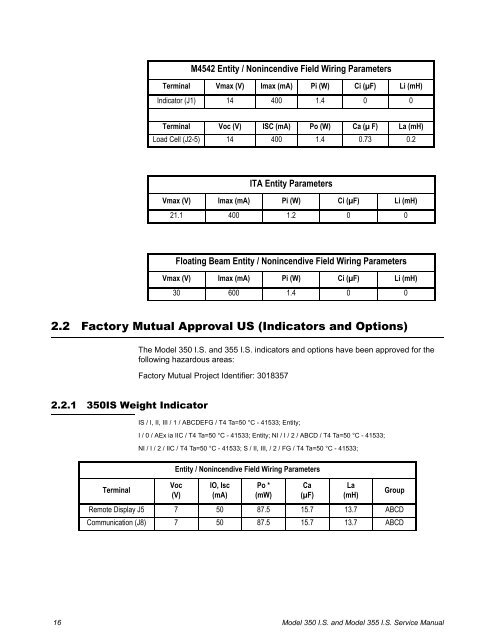
M4542 Entity / Nonincendive Field Wiring ParametersTerminal Vmax (V) Imax (mA) Pi (W) Ci (µF) Li (mH)Indicator (J1) 14 400 1.4 0 0Terminal Voc (V) ISC (mA) Po (W) Ca (µ F) La (mH)Load Cell (J2-5) 14 400 1.4 0.73 0.2ITA Entity ParametersVmax (V) Imax (mA) Pi (W) Ci (µF) Li (mH)21.1 400 1.2 0 0Floating Beam Entity / Nonincendive Field Wiring ParametersVmax (V) Imax (mA) Pi (W) Ci (µF) Li (mH)30 600 1.4 0 02.2 Factory Mutual Approval US (Indicators and Options)The Model 350 I.S. and 355 I.S. indicators and options have been approved for thefollowing hazardous areas:Factory Mutual Project Identifier: 30183572.2.1 350IS Weight IndicatorIS / I, II, III / 1 / ABCDEFG / T4 Ta=50 °C - 41533; Entity;I / 0 / AEx ia IIC / T4 Ta=50 °C - 41533; Entity; NI / I / 2 / ABCD / T4 Ta=50 °C - 41533;NI / I / 2 / IIC / T4 Ta=50 °C - 41533; S / II, III, / 2 / FG / T4 Ta=50 °C - 41533;TerminalEntity / Nonincendive Field Wiring ParametersVoc(V)IO, Isc(mA)Po *(mW)Ca(µF)La(mH)GroupRemote Display J5 7 50 87.5 15.7 13.7 ABCDCommunication (J8) 7 50 87.5 15.7 13.7 ABCD16Model 350 I.S. and Model 355 I.S. Service Manual
TerminalEntity / Nonincendive Field Wiring ParametersVoc(V)IO, Isc(mA)Po *(mW)Ca(µF)La(mH)GroupRemote Key Input (J11) 7 62 109 15.4 9 ABCDTerminalVt(V)It(mA)Special Condition of Use:Pt *(mW)Ca(µF)La(mH)GroupLoad Cell (J10) 7 400 700 8.3 198 ABCDLoad Cell with alternate 14 400 1400 4.6 945.2 CDexcitation option (J10)When fitted with an alternate Excitation Output Board P/N 420982-0364, the 350IS isnot to be used in a Class I, Division 1, Group A and B or Class I, Zone 0, Group IICHazardous (Classified) Location as shown on Control Drawing 41533 sheet 2.2.2.2 355IS Weight IndicatorIS / I, II, III / 1 / ABCDEFG / T4 Ta=50 °C - 41533; Entity;I / 0 / AEx ia IIC / T4 Ta=50 °C - 41533; Entity; NI / I / 2 / ABCD / T4 Ta=50 °C - 41533;NI / I / 2 / IIC / T4 Ta=50 °C - 41533; S / II, III, / 2 / FG / T4 Ta=50 °C - 41533;TerminalEntity / Nonincendive Field Wiring ParametersVoc(V)IO, Isc(mA)Po *(mW)Ca(µF)La(mH)GroupRemote Display J5 7 50 87.5 15.7 13.7 ABCDCommunication (J8) 7 50 87.5 15.7 13.7 ABCDRemote Key Input (J11) 7 62 109 15.4 9 ABCDTerminalVt(V)It(mA)Special Condition of Use:Pt *(mW)Ca(µF)La(mH)GroupLoad Cell (J10) 7 400 700 8.3 198 ABCDLoad Cell with alternate 14 400 1400 4.6 945.2 CDexcitation option (J10)When fitted with an alternate Excitation Output Board P/N 420982-40364, the 355IS isnot to be used in a Class I, Division 1, Group A and B or Class I, Zone 0, Group IICHazardous (Classified) Location as shown on Control Drawing 41533 sheet 2.Model 350 I.S. and Model 355 I.S. Service Manual 17
- Page 1 and 2: Model 350I.S. and Model 355I.S.Inst
- Page 3 and 4: Table of ContentsChapter 1 General
- Page 5 and 6: Start Fill ........................
- Page 7 and 8: 1 General Information and Warnings1
- Page 9 and 10: 1.3.3 Safe Handling of Equipment wi
- Page 11 and 12: 1.8 FCC and EMC Declarations of Com
- Page 13 and 14: 2 IntroductionThis section explains
- Page 15 and 16: Note: Electrical apparatus Approved
- Page 17: Ca or Co - the maximum capacitance
- Page 21 and 22: GasApprovalTemperatureRangeT class
- Page 23 and 24: 2.5 Standard FunctionsThe Model 350
- Page 25 and 26: Safe Area OptionsBattery ChargerFib
- Page 27 and 28: 2.9 350 I.S. KeypadThe Model 350 I.
- Page 29 and 30: Key Press Weigh Mode Count Mode Set
- Page 31 and 32: 2.11 Weigh Mode FunctionsThe Model
- Page 33 and 34: 3 InstallationThe Model 350/355 I.S
- Page 35 and 36: 3.2.2 Model 355 I.S.Figure 3.3 Mode
- Page 37 and 38: 3.5 Remote Key ConnectionsThe Model
- Page 39 and 40: Battery ChargingTHE BATTERY MUST BE
- Page 41 and 42: 3. Snap the (4) ½ plastic standoff
- Page 43 and 44: Figure 3.12 Fiber-optic Cable Insta
- Page 45 and 46: Install the setpoint or Analog opti
- Page 47 and 48: 3.8.5 Safe Area Analog Option Insta
- Page 49 and 50: 4 ConfigurationThis section covers
- Page 51 and 52: To access the previous parameter1.
- Page 53 and 54: To setup a full scale value (exampl
- Page 55 and 56: 4.5.2 Return to factory default (35
- Page 57 and 58: ParameterNumberDisplayNameP296.00 E
- Page 59 and 60: P115 Stability Delay (Selection)Sel
- Page 61 and 62: P204 Comm Handshake (Comm 1) (Selec
- Page 63 and 64: P292 End Character (Key-in)Set the
- Page 65 and 66: P802 Tare and Zero Execution (Selec
- Page 67 and 68: is an 'O' (overload/underload), 'M'
M4542 Entity / Nonincendive Field Wiring ParametersTerminal Vmax (V) Imax (mA) Pi (W) Ci (µF) Li (mH)Indicator (J1) 14 400 1.4 0 0Terminal Voc (V) ISC (mA) Po (W) Ca (µ F) La (mH)Load Cell (J2-5) 14 400 1.4 0.73 0.2ITA Entity ParametersVmax (V) Imax (mA) Pi (W) Ci (µF) Li (mH)21.1 400 1.2 0 0Floating Beam Entity / Nonincendive Field Wiring ParametersVmax (V) Imax (mA) Pi (W) Ci (µF) Li (mH)30 600 1.4 0 02.2 Factory Mutual Approval US (Indicators and Options)The Model 350 I.S. and 355 I.S. indicators and options have been approved for thefollowing hazardous areas:Factory Mutual Project Identifier: 30183572.2.1 <strong>350IS</strong> <strong>Weigh</strong>t IndicatorIS / I, II, III / 1 / ABCDEFG / T4 Ta=50 °C - 41533; Entity;I / 0 / AEx ia IIC / T4 Ta=50 °C - 41533; Entity; NI / I / 2 / ABCD / T4 Ta=50 °C - 41533;NI / I / 2 / IIC / T4 Ta=50 °C - 41533; S / II, III, / 2 / FG / T4 Ta=50 °C - 41533;TerminalEntity / Nonincendive Field Wiring ParametersVoc(V)IO, Isc(mA)Po *(mW)Ca(µF)La(mH)GroupRemote Display J5 7 50 87.5 15.7 13.7 ABCDCommunication (J8) 7 50 87.5 15.7 13.7 ABCD16Model 350 I.S. and Model 355 I.S. <strong>Service</strong> <strong>Manual</strong>


