Load Transfer from one Feeder to other during Transformer ...
Load Transfer from one Feeder to other during Transformer ...
Load Transfer from one Feeder to other during Transformer ...

Create successful ePaper yourself
Turn your PDF publications into a flip-book with our unique Google optimized e-Paper software.
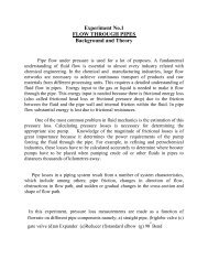
<strong>Load</strong> <strong>Transfer</strong> <strong>from</strong> <strong>one</strong> <strong>Feeder</strong> <strong>to</strong> <strong>other</strong> <strong>during</strong><strong>Transformer</strong> MaintenanceWhen transformer is <strong>to</strong> be taken out for service maintenance, thecorresponding circuit breaker should be turned off and GOS has <strong>to</strong> beopened. But there is a requirement for constant power delivery <strong>to</strong> thefeeder, so the bus coupler has <strong>to</strong> be closed, <strong>to</strong> route the current <strong>from</strong><strong>one</strong> branch <strong>to</strong> an<strong>other</strong> i.e. <strong>to</strong> the branch which was getting fed by thetransformer which is taken out for maintenance. Let us see powertransformer, circuit breaker, isola<strong>to</strong>r, instrument transformer and buscoupler in detail :<strong>Transformer</strong>sThe main advantage of alternating currents over direct currentsis that, the alternative currents can be easily transferable <strong>from</strong> lowvoltage <strong>to</strong> high or high voltage <strong>to</strong> low. Alternating voltages can be raisedor lowered as per requirements in the different stages of electricalnetworks as generation, transmission, distribution and utilization. This ispossible with a state device called transformer. The transformer workson principle of mutual induction. It transfers an electrical energy <strong>from</strong><strong>one</strong> circuit <strong>to</strong> <strong>other</strong> when there is no electrical connection between thetwo circuits. Thus we can define transformer as below:Key point: The transformer is a static piece of apparatus by means ofwhich an electrical power is transferred <strong>from</strong> <strong>one</strong> alternating currentcircuit <strong>to</strong> an<strong>other</strong> with the desired change in voltage and current withoutany change in frequency.As an example, see the fig below <strong>to</strong> see how transformers are used intransmission system:
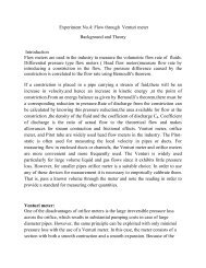
Use of transformers in transmission systemFig (a)Trivia: - DC supply cannot be used for the transformers.Principle of workingIt works on the principle of mutual induction, mutual inductionstates that when 2 coils are inductively coupled and if current in <strong>one</strong> coilis changed informally then an e.m.f. gets induced in the <strong>other</strong> oil. Thise.m.f. can drive a current, when a closed path is provided <strong>to</strong> it. Thetransformer works on the same principle.The basic transformer is shown in figure below
Basic transformerFig (b)An alternating voltage source is connected <strong>to</strong> <strong>one</strong> of the coils. Thiscoil in which electrical energy is fed with the help of source is calledprimary winding (p).The <strong>other</strong> winding is connected <strong>to</strong> the load. Theelectrical energy which is transformed <strong>to</strong> this winding is drawn out <strong>to</strong> theload. This winding is called secondary winding(s).The primary windinghas N 1 number of turns while the secondary has N 2 number of turns.
Symbolic representation of a transformerFig (c)The secondary voltage depends on the number of turns in primaryand secondary winding. The secondary voltage will be having differentvoltage level but same frequency as the primary.
Ratios of transformerFig (d)Voltage RatioThe ratio of secondary induced e.m.f. <strong>to</strong> primary induced e.m.f. is knownas voltage transformation ratio denoted as K.(E 2 /E 1 ) = (N 2 /N 1 ) = KK = (N 2 /N 1 )
Note:-1) If N 2 > N 1 i.e. :K >1We get E 2 > E 1 then the transformer is called step up transformer.2) If N 2 < N 1 i.e. :K < 1We get E 2 < E 1 then the transformer is called step downtransformer.3) If N 2 = N 1 i.e. :K =1We get E 2 = E 1 then the transformer is called isolation or 1:1transformer.Ideal transformerIdeal transformer has following properties:1) No losses2) Windings have zero resistance.3) All the flex produced by primary links with the secondary i.e.leakage flex is zero.4) Permeability of core is so high that negligible current is required <strong>to</strong>establish the flex in it.Current ratioIn an ideal transformer there are no losses. Therefore the product ofprimary voltage V 1 and primary current I 1 ,is same as the product ofsecondary voltage V 2 and the secondary current I 2.So V1 I 1 = input VA and V 2 I 2 = output VA.For an ideal transformer,V 1 I 1 = V 2 I 2(V 2 /V 1 ) = (I 1 /I 2 ) = KTherefore the current are in the inverse ratio of the voltagetransformative ratio.
Taps or Tap changerThe transformer is provided with a taps in order <strong>to</strong> adjust thevoltage ratio of the transformer. These taps are provided along thewinding with connections <strong>to</strong> a tap-changing device that makes thephysical change in the in-service tap. The tap changing device is usuallyplaced on the primary winding <strong>to</strong> minimize the current <strong>to</strong> be switchedand can be “off-circuit “ or “on-load” type .When the primary voltage islow, the tap changer reduces correspondingly the number of primaryturns <strong>to</strong> maintain the secondary voltage constant. Similarly, when theprimary voltage is high, the tap changer increases correspondingly thenumber of primary turns <strong>to</strong> maintain the secondary voltage constant.Off-circuit tapsIn industrial power system, off-circuit taps are used with dry-typetransformer, liquid-immersed transformer, when they are not connecteddirectly <strong>to</strong> the utility power supply. On the primary (high voltage side) ofstep-down transformer, four full-capacity taps (five positions) areprovided in four 2.5% steps, 2 above and 2 below normal. The tapchangermechanism should change the taps on all three phasessimultaneously. Also, it should be operable form ground level, with tapchanger position for padlocking. Important thing here <strong>to</strong> be noticed isthat the transformer must be de-energized before the tap changermechanism is operated.On-load tap changerOn-load tap changers (OLTC) are mostly with oil-immersedtransformer connected <strong>to</strong> the utility power supply at a voltage levelexceeding 34.5kV.Because the majority of power companies stipulated avoltage variation of ± 10 % in the power contract, the tap changer isprovided with an equivalent range of voltage regulation of ± 10 % in 16 or32 steps.16 step tap changer provides 5/4% voltage change in eachstep.32step tap changer provides 5/8% voltage change in each stepthus more preferred.
When the tap-changer design requires an oil-expansion tank, itshall be piped <strong>to</strong> a separate compartment in the conserva<strong>to</strong>r. A separatetap-changer gas-detec<strong>to</strong>r relay is located in this pipe.The tap-changing control equipment includes:1) Control and paralleling equipment.2) Line drop compensation equipment along with the currenttransformer <strong>to</strong> provide voltage control at a point remote <strong>from</strong> themeasuring point.· Au<strong>to</strong>matic voltage-regulating relay.· Weather proof control cabinet, accessible <strong>from</strong> ground level.
Oil-filled(immersed) transformersOil filled transformer makes use of oil for the cooling of major parts of atransformer.Fig(e)Oil filled transformers are transformers filled with a highly refined mineraloil that is used <strong>to</strong> insulate internal live parts of the transformer. The oilprevents corona and manages temperature control inside thetransformer for the prevention of equipment and machinery overheating<strong>during</strong> the operation of large job applications. Because of oil inside the
transformer being of non-combustible properties, these transformers arevery safe and can operate machinery for long period of time.Oil or liquid preservation system for oil-filled transformerA preservation system is essential for a liquid-immersed transformer <strong>to</strong>allow- expansion and contraction of the liquid due <strong>to</strong> the changes in thetemperature with-out exposing the insulating liquid <strong>to</strong> externalcontamination. The expansion space is known as “the oil preservationsystem”. There are four different designs :· Sealed tank· Gas-oil seal· Conserva<strong>to</strong>r· Conserva<strong>to</strong>r diaphragmLet us see conserva<strong>to</strong>r design in detail :The conserva<strong>to</strong>r is an oil-expansion tank mounted above the highest oilpoint on the transformer. The transformer tank and conserva<strong>to</strong>r areconnected through a pipe, and a gas-detec<strong>to</strong>r relay (buchholz relay ) isinstalled in the pipe. The transformer oil expands and contracts with theincrease and decrease of the oil temperature. The conserva<strong>to</strong>r musttherefore breathe <strong>to</strong> the surrounding air, and moisture in the air can beabsorbed in<strong>to</strong> the oil and insulation system. To prevent the moisture<strong>from</strong> entering the conserva<strong>to</strong>r, a silica gel breather is provided that willdry the air as the breathing takes place. As the silica gel absorbs themoisture, it will change <strong>from</strong> blue <strong>to</strong> pink in colour and must be changed<strong>to</strong> retain its drying capability. So maintenance is required.The accessories for mineral-oil transformer generally consists of :· A conserva<strong>to</strong>r tank.· Buchholz relay ( gas-detec<strong>to</strong>r relay ) for conserva<strong>to</strong>r-typetransformer. Buchholz relay is located in the pipe between thehighest part of the transformer tank and conserva<strong>to</strong>r. The relayconsists of two sets of contacts, <strong>one</strong> contact for trip upon surgeand <strong>other</strong> alarm upon gas accumulation.· Breather of dehydrating type for conserva<strong>to</strong>r-type transformerscontaining a colour indica<strong>to</strong>r( usually silica gel), piped <strong>to</strong> theconserva<strong>to</strong>r and mounted in such a way that it is accessible <strong>from</strong>
ground level.· Winding temperature-indica<strong>to</strong>r.· Oil temperature indica<strong>to</strong>r.· Cooling equipment like radia<strong>to</strong>rs, fans for forced air cooling, andpumps for forced oil – and water- cooled transformer.Instrument transformersIt is not practicable <strong>to</strong> connect instruments and meters directly <strong>to</strong> thelines in high voltage circuits, so instrument transformers are used. Thetwo basic advantages of this method are:· Standard rated instruments may be used easily.· Operating personnel coming in contact with the instruments arenot subjected <strong>to</strong> high voltage and currents of the lines, and s<strong>other</strong>e is less danger <strong>to</strong> them. Even with a low-voltage system,instrument transformers are used for measuring large currents, sothat heavy leads <strong>to</strong> the instrument panel and <strong>to</strong> the ammeter and<strong>other</strong> current terminals are avoided.The instrument transformers are classified as follows:a) Potential transformersb) Current transformersPotential transformers(P.T.):A potential transformer is a step down transformer used along with a lowrange voltmeter for measuring a high voltage. The primary is connectedacross the high voltage supply and the secondary <strong>to</strong> the voltmeter orpotential coil of the wattmeter. Since the voltmeter (or potential coil)impedance is very high, the secondary current is very small and thepotential transformer behaves as an ordinary two winding transformeroperating on no load.
Fig (f)The above fig shows a potential transformer used <strong>to</strong> measure thevoltage of a circuit. It may be noted that the secondary is grounded. Thisis d<strong>one</strong> so that if the insulation breaks down, the high voltage does notendanger personnel who may be reading the meters.These transformers are made with high quantity iron core operating atvery low flux densities so that the magnetising current may be verysmall. Careful designs ensure minimum variation of voltage ratio withload and minimum phase shift between input and output voltages.Potential transformers secondary are commonly designed for an outpu<strong>to</strong>f 110V.Current transformers :The range of the D.C. ammeter is extended using a shunt, similarly acurrent transformer performs the same function in A.C. circuits. Thus ahigh magnitude A.C. can be measured by a combination of currenttransformer and a low range ammeter.In current transformer, the primary side consists of a very few turns ofthick cross-section connected in series with the high current lines.Mostly, the primary is just <strong>one</strong> turn formed by taking the line conduc<strong>to</strong>rthrough the secondary winding (fig (g).
Fig (g)Line conduc<strong>to</strong>r acting as primaryThe secondary winding consists of large number of turns of fine wiredesigned for either 5A or 1A rating. Thus a current transformer is a stepup transformer. The current transformer has the secondary effectivelyshort-circuited through the low impedance of the ammeter. The fig (h)below shows the current transformer connections.Fig (h)
The current transformer ratio is not equal <strong>to</strong> the ratio of secondary <strong>to</strong>primary turns, mainly because of the effect of magnetizing current.A current transformer must never be operated on open circuit for thefollowing reasons:· There will be no secondary m.m.f. and since the primarycurrent(and m.m.f.) is fixed, the core flux will increaseenormously. This will cause large amount of eddy current andhysteresis losses and the resulting high temperature may damagethe insulation or even the core.· As the secondary side is open , a very high voltage will beinduced in the multi-turn secondary and this high voltage isdangerous <strong>to</strong> both life and <strong>to</strong> the insulation.Fig (i)The above diagram shows the wiring diagram for potential and currentinstrument transformers.
Circuit breakersA circuit breaker is an au<strong>to</strong>matically operated electrical switch designedfor <strong>to</strong> protect an electrical circuit <strong>from</strong> damage caused by overload orshort circuit. Or, in <strong>other</strong> words, the function of a circuit breaker is <strong>to</strong>isolate the faulty part of the power system in case of abnormalconditions. A protective relay detects abnormal conditions and sends atripping signal <strong>to</strong> the circuit breaker. After receiving the trip commandsignal <strong>from</strong> the relay the circuit breaker isolates the faulty part of thepower system.Fig (j)Separation of the contacts of the circuit breakerA circuit breaker has two contacts- a fixed contact and a moving contact.Under normal conditions these two contacts remain in closed position.When the circuit breaker is required <strong>to</strong> isolate the faulty part, the movingcontact moves <strong>to</strong> interrupt the circuit. On the separation of the contacts,the flow of current is interrupted, resulting in the formation of an arcbetween the contacts. These contacts are placed in a closed chambercontaining some insulating medium (like gas or liquid) which extinguishthe arc.
Insulating fluid is used for arc extension and the fluid chosen dependsupon the rating and type of circuit breaker. The insulating fluidscommonly used for circuit breaker are:(i) Air at atmospheric pressure(ii) Compressed air(iii) Ultra high vacuum(iv) Oil which produces hydrogen for arc extension(v) Sulphur hexafluoride (SF 6 )Some of the gases which have been used in circuit breaker are:· Electromagnetic gases : Sulphur hexafluoride , arc<strong>to</strong>n· Simple gases: Air, oxygen, hydrogen, nitrogen and carbon dioxide.The important characteristics of the fluids used in circuit breaker are:(i)(ii)(iii)(iv)It should have good thermal and chemical stabilityIt should have high declarative strength.Non-inflammability and high thermal conductivity.Arc extinguish ability.Classification of circuit breakers(1) High voltage circuit breakers(2) Low voltage circuit breakersHigh voltage circuit breakers :-(a) Oil circuit breakers :-(i) Bulk oil circuit breakers using a large quantity of oil.(ii) Low oil circuit breakers which operate with a minimumamount of oil.(b) Oil less circuit breakers :-(i) Hard gas circuit breakers(ii) Air blast circuit breakers(iii) Sulphur hexafluoride circuit breaker
(iv)(v)Water circuit breakersVacuum circuit breakersCharacteristics of high voltage rating circuit breaker :-(i)(ii)High voltage rating circuit breaker should have high reliabilityelectrically and mechanically.High voltage rating circuit breaker should be capable ofinterrupting capacitive and inductive circuits and fault currentsof all values within their rating.Let us see some of the features of major circuit breakers:(1) OIL CIRCUIT BREAKERS (O.C.B)Oil circuit breakers are the most common and oldest type of circuitbreakers. The rating range of circuit breakers lies in range of25MVA at 2.5kV and 5000MVA at 250kV.In oil circuit breaker, the separating contacts are made <strong>to</strong> separatewithin insulating oil medium, which has better insulating propertiesthan air.Few advantages of using oil as an Arc quenching medium:-(a) Dielectric strength is high(b) As a result of decomposition of oil, it has good cooling property.(c) It acts as an insula<strong>to</strong>r between live part and earth.(d) Surrounding oil in close proximity <strong>to</strong> the arc presents a largecooling surface.Few disadvantages:-(a) Highly inflammable and can cause an explosion by mixing withair.(b) It requires maintenance.(c) Periodic replacement.
(2) AIR BLAST CIRCUIT BREAKERS:-Air blast circuit breakers is a type of circuit breaker which use ahigh pressure air blast (at a pressure of 20bar) as an arcquenching medium.Range – 132kV and above up <strong>to</strong> 400kV ,with the braking capacityup <strong>to</strong> 7500MVA .But can also be designed <strong>to</strong> cover the wide rangeof 66kV <strong>to</strong> 132kV.Few advantages:-(a) No risk of explosion and fire hazards.(b) Consistent and short arc duration(c) Since the arc duration is short and consistent, the burning of thecontact is less due <strong>to</strong> less arc energy.(d) High speed enclosures facility.(e) Comparatively less maintenance required.Few disadvantages:-(a) Current chopping(b) Sensitivity <strong>to</strong> restricting voltage(3) SULPHUR HEXAFLUORIDE(SF 6 ) CIRCUIT BREAKER:-Sulphur hexafluoride <strong>to</strong> <strong>other</strong> medium such as oil or air for the usein circuit breakers for the following reasons:(1) Being an Inert gas, it is non-reactive <strong>to</strong> the <strong>other</strong> comp<strong>one</strong>ntsof circuit breakers.(2) Sulphur hexafluoride has high dielectric strength (about 24times that of air and it is comparable <strong>to</strong> that of oil)(3) When extinction of arc is concerned it is about 100 times moreeffective than air.(4) Its heat transfer property is about 16times that of air because ofits high density.Applications:-(1) The circuit breakers are designed for voltages 115kV <strong>to</strong> 230kV,power rating of 10MVA <strong>to</strong> 20MVA and interrupting times lessthan 3cycles.
(2) A typical sulphur hexafluoride circuit breaker consist ofinterrupter units, each capable of dealing with currents up <strong>to</strong>60000A and voltage in the range of 50 <strong>to</strong> 80kV.A number ofunits are connected in series according <strong>to</strong> the voltage of thesystem.Few Advantages:-(a) No risk of fire.(b) No reduction of dielectric strength.(c) Arcing time is very short; this reduces the erosion of contact.(d) Its operation is very silent.(e) The current chopping tendency is minimized by usingsulphur hexafluoride gas at low pressure and low velocity.(f) The breaker is compact in size and <strong>to</strong>tally enclosed. Thuselectrical clearances are drastically reduced and areparticularly suitable where explosion hazard exists, like coalmines.Disadvantages:-(a) Expensive(b) Sulphur hexafluoride gas has <strong>to</strong> be reconditi<strong>one</strong>d after everyoperation of the breaker and additional equipment is requiredfor this purpose.(3) VACUUM CIRCUIT BREAKERS(V.C.B):-Vacuum means the pressure below atmospheric pressurewhich is 760 mm of Hg. In a vacuum circuit breaker, vacuum ofthe order of 10 -5 <strong>to</strong> 10 -7 (1 <strong>to</strong>rr = 1 mm of Hg) is used as the arcquenching medium. The dielectric strength of the vacuum is1000 times more than that of any <strong>other</strong> medium.Applications:-(1) Vacuum breakers are being used for outdoor applicationsranging <strong>from</strong> 22kV <strong>to</strong> 66kV. They are also suitable for
majority of applications in several areas even with limitedrating say 60 <strong>to</strong> 100MVA.(2) Vacuum circuit breakers are used for capaci<strong>to</strong>r-bankswitching, transformer, reacting switching, where thevoltages are high and current <strong>to</strong> be interrupted is low.Few important terms regarding circuit breakers:-(1) Arc voltage :-The voltage across the contacts <strong>during</strong> the arcing period isknown as the “arc voltage “.(2) Restriking voltage:-The transient voltage appearing across the contacts <strong>during</strong>arc period is called the “restriking voltage”.(3) Recovery voltage:-It is normal frequency (50Hz) r.m.s. voltage that appearsacross the contact of the circuit breaker after the finalextinction. It is approximately equal <strong>to</strong> the system voltage.(4) Rate of Rise of restriking voltage(RRRV):-The average RRRV =Peak value of restriking voltageTime taken <strong>to</strong> reach the peak value(5) Current Chopping:-When low inductive current (e.g. current <strong>to</strong> a shunt reac<strong>to</strong>ror magnetising current of a transformer) is interrupted by acircuit breaker and the arc quenching force of the circuitbreaker is more than necessary <strong>to</strong> interrupt a low magnitudeof current, the current will be interrupted before its manualzero instant. It is termed as current chopping.Rating of circuit breakers:-A circuit breaker is expected <strong>to</strong> perform the following duties (besidesnormal working) under short circuit/fault conditions:(a) To open the contacts <strong>to</strong> clear the fault and isolating the faultysection.
(b) To close the contacts on <strong>to</strong> a fault.(c) It must be able <strong>to</strong> carry fault current for a short time while an<strong>other</strong>circuit breaker (in series) is clearing the fault.Therefore, in addition <strong>to</strong> the rated voltage, current andfrequency, circuit breakers have the following important ratings.(i) Breaking capacity(ii) Making capacity(iii) Short-time capacity(i)(ii)(iii)Breaking capacity:-It is the current (r.m.s. value) that a circuit breaker is capable ofbreaking under specified conditions (e.g. PPPV, power fac<strong>to</strong>r)and given recovery voltage.Breaking capacity for a 3-phase circuit breaker = √3 × ×10 -6 MVA ;Where V=Rated service lines in volts,I =rated breaking current (symmetrical or asymmetrical)in ampere.Making capacity:-The peak value of current (including the DC comp<strong>one</strong>nt) <strong>during</strong>first cycle of current wave after the closure of circuit breaker isknown as “making capacity”.Making capacity = 2.55 × symmetrical breaking capacityShort-time capacity:-The short time rating of a circuit breaker depends upon itsability <strong>to</strong> withstand the temperature rise and the electromagneticforce effects. The oil circuit breakers have a specified limit of 3seconds when the ratio of symmetrical breaking current <strong>to</strong> therated normal current does not exceed 40. However if this ratioexceeds 40, then the specified limit is 1second.
Normal current rating:-It is the r.m.s. value of current which the circuit breaker iscapable of carrying continuously at its rated frequency underspecified conditions.Bus-barIn electrical power distribution, a bus bar is a strip of copper oraluminium that conducts electricity within a switchboard, distributionboard, substation or <strong>other</strong> electrical apparatus.The size of the bus bar determines the maximum amount of current thatcan be safely carried. Bus bars can have a cross-sectional area of aslittle as 10 mm2 but electrical substations may use metal tubes of 50 mmin diameter (1,963 mm2) or more as bus bars.Bus bars are typically either flat strips or hollow tubes as these shapesallow heat <strong>to</strong> dissipate more efficiently due <strong>to</strong> their high surface area <strong>to</strong>cross-sectional area ratio. The skin effect makes 50–60 Hz AC bus barsmore than about 8 mm (1/3 in) thick inefficient, so hollow or flat shapesare prevalent in higher current applications.Note: Skin effect is the tendency of an alternating electric current (AC) <strong>to</strong>distribute itself within a conduc<strong>to</strong>r with the current density being largestnear the surface of the conduc<strong>to</strong>r, decreasing at greater depths.
Fig (k)1500 ampere bus bars within a power distribution rack for a largebuildingA bus bar may either be supported on insula<strong>to</strong>rs, or else insulation maycompletely surround it. Bus bars are protected <strong>from</strong> accidental contacteither by a metal earthed enclosure or by elevation out of normal reach.Neutral bus bars may also be insulated. Earth bus bars are typicallybolted directly on<strong>to</strong> any metal chassis of their enclosure. Busbars maybe enclosed in a metal housing, in the form of bus duct or busway,segregated-phase bus, or isolated-phase bus.Bus bars may be connected <strong>to</strong> each <strong>other</strong> and <strong>to</strong> electrical apparatus bybolted, clamp, or welded connections. Often joints between high-currentbus sections have matching surfaces that are silver-plated <strong>to</strong> reduce thecontact resistance.
Fig (l)Solid isolated busbar systemWhen several feeders or genera<strong>to</strong>rs operating at the same voltage have<strong>to</strong> be directly connected electrically, bus-bars are used as the comm<strong>one</strong>lectrical equipment. The bus-bars provide adequate operating flexibility,cost reduction and sufficient reliability.Bus-bar arrangements:· Single bus-bar system.· Double bus-bar system with sectionalisation.Single bus-bar system:In case of a power plant which has number of genera<strong>to</strong>rs and singlebus-bar arrangement, the bus-bar is sectionalised by circuit breakers.The major advantage of this type of system is that fault on <strong>one</strong> part ofthe bus-bar or system does not completely shut down the whole station.
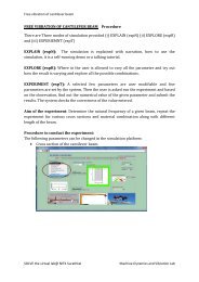
Single bus-bar systemFig (m)G=genera<strong>to</strong>r, GOS= group operated switches, CB=circuit breaker,TR=step up transformer.
Double bus-bar system :In this system both low voltage and voltage bus-bars are duplicated, anyof the bus-bar sections can be used as desired. There is a provision of abus-bar coupling switch for transferring operation <strong>from</strong> <strong>one</strong> bus-bar <strong>to</strong>an<strong>other</strong>.Double bus-bar systemFig (n)Note: Bus coupler is a device which is used switch <strong>from</strong> <strong>one</strong> bus <strong>to</strong> the<strong>other</strong> without any interruption in power supply and without creatinghazardous arcs. It is achieved with the help of circuit breaker andisola<strong>to</strong>rs.
Isola<strong>to</strong>r switch (Group operated switches)Isola<strong>to</strong>rs are known as disconnec<strong>to</strong>r or isola<strong>to</strong>r switch. Isola<strong>to</strong>r is used <strong>to</strong>make sure that an electrical circuit can be completely de-energized forservice or maintenance. Such switches are often found in electricaldistribution and industrial applications where machinery must have itssource of driving power removed for adjustment or repair. High-voltageisolation switches are used in electrical substations <strong>to</strong> allow isolation ofapparatus such as circuit breakers and transformers, and transmissionlines, for maintenance.Isola<strong>to</strong>r switches have provisions for a padlock so that inadverten<strong>to</strong>peration is not possible . In high voltage or complex systems, thesepadlocks may be part of a trapped-key interlock system <strong>to</strong> ensure propersequence of operation. In some designs the isola<strong>to</strong>r switch has theadditional ability <strong>to</strong> earth the isolated circuit thereby providing additionalsafety. Such an arrangement would apply <strong>to</strong> circuits which inter-connectpower distribution systems where both end of the circuit need <strong>to</strong> beisolated.Isola<strong>to</strong>rs are manually operated or mo<strong>to</strong>rized. When the isola<strong>to</strong>r isopened, it can be visually seen and hence service men are assured thatis safe <strong>to</strong> work on the isolated equipment. The major difference betweenan isola<strong>to</strong>r and a circuit breaker is that an isola<strong>to</strong>r is an off-load deviceintended <strong>to</strong> be opened only after current has been interrupted by some<strong>other</strong> control device.
Fig (o)110kv isola<strong>to</strong>r in closed position