


You also want an ePaper? Increase the reach of your titles
YUMPU automatically turns print PDFs into web optimized ePapers that Google loves.
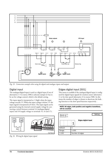
Relay outputsPTC inputPTCCurrent transformerDigIn 1 DigIn 2 +12 V AnIn GND DigIn 3 DigIn 4 +12 V AnOut CT1 CT2 CTc11 12 13 14 15 16 17 18 19 75 76 77Start/stopAnaloguereferenceParameter setMeasuringDigital inputsAnalogue/digitalinAnalogueoutDigital inputsFig. 53 Connection example when using the digital and analogue inputs and outputsDigital inputThe analogue/digital input is used as a digital input if one ofalternatives 1-5 in menu [500] is selected. Jumper J1 has tobe set for voltage control, which is the default setting.The input signal is interpreted as 1 (high) when the inputvoltage exceeds 5 V. When the input voltage is below 5 V theinput signal is interpreted as 0 (low). The input signal can begenerated using the internal control supply voltage by connectinga switch between terminal 14 (analogue/digitalinput) and 18 (supply voltage to terminals 14, 16 and 17).Edges digital input [501]This menu is available if the analogue/digital input is configuredfor digital input signals for rotation sensor (alternative1) or for slow speed (alternative 2) in menu [500]. In thismenu the number of edges is chosen to deactivate the brakingfunction or the slow speed function respectively. .NOTE: All edges, both positive and negative transitions,will be counted.5 0 1Setting1Edges digital inputFig. 54 Wiring for digital input signal.Default: 1Range: 1-1001-100 Number of edges78 Functional description <strong>Emotron</strong> AB 01-4135-01r2


