supra 644, 744, 844 beginning with serial# hfy90593608 - Sunbelt ...
supra 644, 744, 844 beginning with serial# hfy90593608 - Sunbelt ...
supra 644, 744, 844 beginning with serial# hfy90593608 - Sunbelt ...

You also want an ePaper? Increase the reach of your titles
YUMPU automatically turns print PDFs into web optimized ePapers that Google loves.
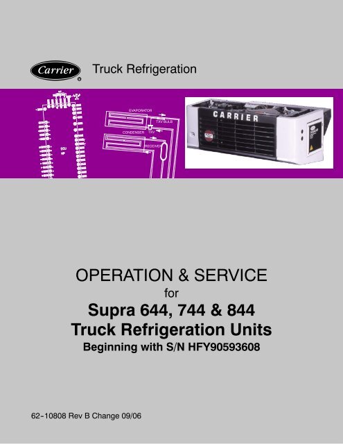
OPERATION ANDSERVICE MANUALFORSupra <strong>644</strong>, <strong>744</strong> & <strong>844</strong>TRUCK REFRIGERATION UNITS
TABLE OF CONTENTSPARAGRAPH NUMBERPageSAFETY SUMMARYSafety-1DESCRIPTION .......................................................................... 1-11.1 INTRODUCTION ................................................................ 1-11.2 GENERAL DESCRIPTION ........................................................ 1-11.3 CONDENSING SECTION ........................................................ 1-11.3.1 Engine ...................................................................... 1-11.3.2 Clutch Assembly ............................................................. 1-41.3.3 Standby Motor ............................................................... 1-41.3.4 Alternator/Regulator .......................................................... 1-41.3.5 Compressor ................................................................. 1-41.3.6 Compressor Unloader ........................................................ 1-41.3.7 Condenser/Subcooler ......................................................... 1-51.3.8 Accumulator ................................................................. 1-51.3.9 Compressor Pressure Regulating Valve (CPR) ................................... 1-51.3.10 Hot Gas Solenoid Valve ....................................................... 1-51.3.11 Hot Gas Bypass Solenoid Valve ................................................ 1-61.3.12 Filter Drier ................................................................... 1-61.3.13 Receiver .................................................................... 1-61.4 EVAPORATOR SECTION ........................................................ 1-61.4.1 Thermal Expansion Valve ..................................................... 1-61.4.2 Heat Exchanger .............................................................. 1-61.4.3 Evaporator .................................................................. 1-61.4.4 Electric and Water Heat ....................................................... 1-61.5 SYSTEM OPERATING CONTROLS AND COMPONENTS ............................ 1-61.5.1 SWITCHES AND CONTROLS ................................................. 1-71.6 Unit Specifications ............................................................... 1-91.6.1 Engine Data .................................................................. 1-91.6.2 Compressor Data ............................................................. 1-91.7 REFRIGERATION SYSTEM DATA ................................................ 1-101.8 ELECTRICAL DATA ............................................................. 1-101.9 TORQUE VALUES .............................................................. 1-111.10 SAFETY DEVICES ............................................................. 1-111.11 REFRIGERANT CIRCUIT ....................................................... 1-121.11.1 Cooling .................................................................... 1-121.11.2 Heat and Defrost ............................................................ 1-12OPERATION ............................................................................ 2-12.1 MICROPROCESSOR CONTROLLER .............................................. 2-12.1.1 Introduction ................................................................. 2-12.1.2 Digital Display ............................................................... 2-22.1.3 Keypad ..................................................................... 2-22.2 MICROPROCESSOR CONFIGURATION. .......................................... 2-3i 62--10808
TABLE OF CONTENTS - continuedPARAGRAPH NUMBERPage2.3 OPERATOR MICROPROCESSOR SETTINGS ...................................... 2-32.3.1 Setpoint ..................................................................... 2-32.3.2 Functional Parameters ........................................................ 2-32.4 UNIT DATA ..................................................................... 2-52.5 ALARM DISPLAY ................................................................ 2-62.6 PRE-TRIP ...................................................................... 2-82.7 MODES OF OPERATION ........................................................ 2-92.7.1 Startup and Pull Down -- Engine Operation ...................................... 2-92.7.2 Startup and Pull Down -- Standby Operation ..................................... 2-92.7.3 Null Mode Overrides .......................................................... 2-92.7.4 Dual Probe Operation ......................................................... 2-92.7.5 Fuel Heater ................................................................. 2-92.7.6 DEFROST CYCLE .......................................................... 2-102.8 PRE--TRIP INSPECTION ........................................................ 2-102.8.1 Pre-trip Inspection -- Before Starting ........................................... 2-102.8.2 Pre-trip Inspection -- Starting .................................................. 2-102.8.3 Pre-trip Inspection -- After Starting ............................................. 2-102.9 MANUAL START ............................................................... 2-112.10 AUTOMATIC START ............................................................ 2-112.11 STARTING -- STANDBY MOTOR DRIVE .......................................... 2-112.12 STOPPING INSTRUCTIONS ..................................................... 2-112.13 CONTROL CIRCUIT OPERATION -- ENGINE DRIVE ............................... 2-112.14 CONTROL CIRCUIT OPERATION -- STANDBY .................................... 2-122.15 AUTO START SEQUENCE ...................................................... 2-13SERVICE ............................................................................... 3-13.1 MAINTENANCE SCHEDULE ...................................................... 3-13.1 MAINTENANCE SCHEDULE (continued) ........................................... 3-23.2 SERVICING ENGINE RELATED COMPONENTS .................................... 3-33.2.1 Cooling System .............................................................. 3-33.2.2 Changing Lube Oil and Lube Oil Filters .......................................... 3-33.2.3 Replacing the Speed and Run Control Solenoids ................................. 3-33.2.4 Engine Air Cleaner ........................................................... 3-43.2.5 Servicing Fuel Pump .......................................................... 3-53.2.6 Servicing Glow Plugs ......................................................... 3-53.2.7 Alternator ................................................................... 3-53.3 SERVICING AND ADJUSTING V-BELTS ........................................... 3-53.3.1 Belt Tension Gauge ........................................................... 3-53.3.2 Alternator V-Belt ............................................................. 3-63.3.3 Water Pump Belt Tensioner .................................................... 3-63.3.4 Standby Motor--Compressor V-Belt ............................................. 3-63.3.5 Engine--Compressor V-Belts ................................................... 3-662--10808ii
TABLE OF CONTENTS - continuedPARAGRAPH NUMBERPage3.4 PUMPING THE UNIT DOWN OR REMOVING THE REFRIGERANTCHARGE ....................................................................... 3-73.5 REFRIGERANT LEAK CHECKING ................................................ 3-73.6 EVACUATION AND DEHYDRATION ............................................... 3-73.6.1 General ..................................................................... 3-73.6.2 Preparation .................................................................. 3-73.6.3 Procedure for Evacuation and Dehydrating System ............................... 3-83.7 CHARGING THE REFRIGERATION SYSTEM ...................................... 3-83.7.1 Installing a Complete Charge .................................................. 3-83.7.2 Checking the Refrigerant Charge ............................................... 3-93.8 REPLACING THE COMPRESSOR ................................................ 3-93.9 CHECKING 05K COMPRESSOR OILLEVEL ........................................ 3-93.10 COMPRESSOR UNLOADER VALVE .............................................. 3-103.11 CHECKING AND REPLACING FILTER-DRIER ..................................... 3-113.12 CHECKING AND REPLACING HIGH PRESSURE SWITCH ......................... 3-113.12.1 Replacing High Pressure Switch ............................................... 3-113.12.2 Checking High Pressure Switch ............................................... 3-113.13 CHECKING CALIBRATION OF THE DEFROST AIR SWITCH ........................ 3-123.14 CHECKING AND REPLACING EVAPORATORFAN MOTOR BRUSHES & COMMUTATOR ........................................ 3-123.15 EVAPORATOR COIL CLEANING ................................................. 3-123.16 CONDENSER COIL CLEANING .................................................. 3-133.17 HOT GAS (Three-Way) VALVE .................................................... 3-133.17.1 Replacing Solenoid Coil ...................................................... 3-133.18 ADJUSTING THE COMPRESSOR PRESSURE REGULATINGVALVE (CPR) .................................................................. 3-133.19 THERMOSTATIC EXPANSION VALVE ............................................ 3-133.20 MICROPROCESSOR CONTROLLER ............................................. 3-143.21 MICROPROCESSOR REPLACEMENT and CONFIGURATION ...................... 3-153.22 CONTROLLER SENSOR CHECKOUT ............................................ 3-173.23 SUCTION PRESSURE TRANSDUCER ............................................ 3-17TROUBLESHOOTING .................................................................... 4-14.1 DIESEL ENGINE ................................................................ 4-14.1.1 Engine Will Not Start ......................................................... 4-14.1.2 Engine Starts Then Stops ..................................................... 4-14.1.3 Starter Motor Malfunction ..................................................... 4-14.1.3 Starter Motor Malfunction (CONTINUED) ........................................ 4-24.1.4 Malfunction In the Engine Starting Circuit ........................................ 4-24.2 ALTERNATOR (AUTOMOTIVE TYPE) ............................................. 4-24.3 REFRIGERATION ............................................................... 4-34.3.1 Unit Will Not Cool ............................................................ 4-3iii 62--10808
TABLE OF CONTENTS - continuedPARAGRAPH NUMBERPage4.3.2 Unit Runs But Has Insufficient Cooling .......................................... 4-34.3.3 Unit Operates Long or Continuously in Cooling ................................... 4-34.3.4 Unit Will Not Heat or Has Insufficient Heating .................................... 4-34.3.5 Defrost Cycle Malfunction ..................................................... 4-44.3.6 Abnormal Pressure ........................................................... 4-44.3.6.1 Cooling ..................................................................... 4-44.3.6.2 Heating .................................................................... 4-54.3.7 Abnormal Noise .............................................................. 4-54.3.8 Control System Malfunction .................................................... 4-54.3.9 No Evaporator Air Flow or Restricted Air Flow .................................... 4-54.3.10 Expansion Valve Malfunction ................................................... 4-64.3.11 Hot Gas (Three-Way) Valve Malfunction ......................................... 4-64.4 Standby Motor Malfunction ........................................................ 4-6ELECTRICAL SCHEMATIC WIRING DIAGRAM ............................................. 5-15.1 INTRODUCTION ................................................................ 5-1LIST OF ILLUSTRATIONSFIGURE NUMBERPageFigure 1-1. Condensing Section -- Top View/Cab Command .................................... 1-2Figure 1-2. Unit Curbside View ............................................................. 1-3Figure 1-3. Unit Roadside View ............................................................. 1-3Figure 1-4. Cylinder Head -- Unloaded ...................................................... 1-4Figure 1-5. Cylinder Head -- Loaded ........................................................ 1-5Figure 1-6. Hot Gas Valve -- Cooling Flow ................................................... 1-5Figure 1-7. Hot Gas Valve -- Heat and Defrost Flow ........................................... 1-6Figure 1-8. Water and Electric Heat Components ............................................ 1-7Figure 1-9. Electrical Box .................................................................. 1-8Figure 1-10. Control Relay Board .......................................................... 1-8Figure 1-11. Refrigeration Circuit .......................................................... 1-13Figure 2-1. Cab Command ................................................................ 2-1Figure 2-2. Auto Start Sequence .......................................................... 2-13Figure 3-1. Coolant System ................................................................ 3-3Figure 3-2. Speed and Run Control Solenoids ................................................ 3-4Figure 3-3. Fuel System ................................................................... 3-4Figure 3-4. Electric Fuel Pump ............................................................. 3-5Figure 3-5. 70 Amp Alternator (P/N 30--60050--04) ............................................ 3-5Figure 3-6. V-Belt Arrangement ............................................................ 3-6Figure 3-7 Belt Tension Gauge (Part No. 07-00203) ........................................... 3-6Figure 3-8. Vacuum Pump Connection ...................................................... 3-8Figure 3-9. Compressor -- Model 05K ...................................................... 3-10Figure 3-10. Unloader Solenoid Valve ...................................................... 3-1162--10808iv
LIST OF ILLUSTRATIONS - continuedFIGURE NUMBERPageFigure 3-11. Typical Setup for Testing High Pressure Switch ................................... 3-11Figure 3-12. Defrost Air Switch Test Setup .................................................. 3-12Figure 3-13. Fan Motor Brushes ........................................................... 3-12Figure 3-14 Hot Gas (HGS2) or Condenser Pressure Control Solenoid ......................... 3-13Figure 3-15. Compressor Pressure Regulating Valve ......................................... 3-13Figure 3-16. Thermostatic Expansion Valve ................................................. 3-14Figure 3-17. Thermostatic Expansion Valve Bulb and Thermocouple ........................... 3-14Figure 5-1. Electrical Schematic Wiring Diagram .............................................. 5-2LIST OF TABLESTABLE NUMBERPageTable 1-1. Model Chart ................................................................... 1-1Table 1-2. Additional Support Manuals ...................................................... 1-1Table 1-3. Safety Devices -- Microprocessor Controller ....................................... 1-11Table 2-1. Function Parameters ............................................................ 2-3Table 2-2. Unit Data Codes ................................................................ 2-5Table 2-3. Alarm Display .................................................................. 2-7Table 2-4. Manual Glow Time ............................................................. 2-11Table 3-1. Belt Tension (See Figure 3-5) ..................................................... 3-5Table 3-2. Connection Point Voltage ....................................................... 3-14Table 3-3. Configuration Settings .......................................................... 3-16Table 3-4. Sensor Resistance -- Micro Units (ATS,CDT, RAS, SAS & WTS) ..................... 3-17Table 3-6. R-404A Temperature--Pressure Chart ............................................. 3-18v 62--10808
SAFETY SUMMARYGENERAL SAFETY NOTICESThe following general safety notices supplement the specific warnings and cautions appearing elsewhere in thismanual. They are recommended precautions that must be understood and applied during operation and maintenanceof the equipment covered herein. The general safety notices are presented in the following three sections labeled:First Aid, Operating Precautions and Maintenance Precautions. A listing of the specific warnings and cautionsappearing elsewhere in the manual follows the general safety notices.SAFETY PRECAUTIONSYour Carrier Transicold refrigeration unit has been designed <strong>with</strong> the safety of the operator in mind. During normaloperation, all moving parts are fully enclosed to help prevent injury. During all pre-trip inspections, daily inspections,and problem troubleshooting, you may be exposed to moving parts. Stay clear of all moving parts when the unit is inoperation and when the unit main power switch is in the START/RUN position.FIRST AIDAn injury, no matter how slight, should never go unattended. Always obtain first aid or medical attention immediately.OPERATING PRECAUTIONSAlways wear safety glasses. Wear hearing protection as required.Keep hands, clothing and tools clear of the evaporator and condenser fans.No work should be performed on the unit until all circuit breakers and the Emergency Switch are turned off, and batterypower supply is disconnected.Always work in pairs. Never work on the equipment alone.In case of severe vibration or unusual noise, stop the unit and investigate.MAINTENANCE PRECAUTIONSBeware of unannounced starting of the unit. This unit is equipped <strong>with</strong> Auto--Start in both the road and standby modes.The unit may start at any time. When performing any check of the system make certain the Emergency Switch is in theOFF position.Be sure power is turned off before working on motors, controllers, solenoid valves and electrical control switches. Tagcircuit breaker and vehicle ignition to prevent accidental energizing of circuit.Do not bypass any electrical safety devices, e.g. bridging an overload, or using any sort of jumper wires. Problems <strong>with</strong>the system should be diagnosed, and any necessary repairs performed, by qualified service personnel.When performing any arc welding on the unit or container, disconnect all wire harness connectors from themicroprocessor. Do not remove wire harness from the modules unless you are grounded to the unit frame <strong>with</strong> a staticsafe wrist strap.In case of electrical fire, open circuit switch and extinguish <strong>with</strong> CO 2 (never use water).AUTO-STARTYour refrigeration unit is equipped <strong>with</strong> Auto-Start in both Start/Stop and Continuous Run modes. The unit may start atany time. A buzzer will sound for 5 seconds before the unit is started. When performing any check of the refrigerationunit (e.g., checking the belts, checking the oil), make certain that the Start-Run / Off switch is in the OFF (0) position.ENGINE COOLANTThe engine is equipped <strong>with</strong> a pressurized cooling system. Under normal operating conditions, the coolant in theengine and radiator is under high pressure and is very hot. Contact <strong>with</strong> hot coolant can cause severe burns. Do notremove the cap from a hot radiator; if the cap must be removed, do so very slowly in order to release the pressure<strong>with</strong>out spray.REFRIGERANTSThe refrigerant contained in your unit can cause frostbite, severe burns, or blindness when in direct contact <strong>with</strong> theskin or eyes. For this reason, and because of legislation regarding the handling of refrigerants during system service,we recommend that you contact your nearest Carrier Transicold authorized repair facility whenever your unit requiresrefrigeration system service .Safety-162--10808
BATTERYThis unit is equipped <strong>with</strong> a lead-acid type battery. The battery normally vents small amounts of flammable hydrogengas. Do not smoke when checking the battery. A battery explosion can cause serious physical harm and/or blindness.SPECIFIC WARNING AND CAUTION STATEMENTSTo help identify the label hazards on the unit and explain the level of awareness each one carries, an explanation isgiven <strong>with</strong> the appropriate consequences:DANGER -- means an immediate hazard which WILL result in severe personal injury or death.WARNING -- means to warn against hazards or unsafe conditions which COULD result in severe personal injury ordeath.CAUTION -- means to warn against potential hazard or unsafe practice which could result in minor personal injury,product or property damage.The statements listed below are specifically applicable to this refrigeration unit and appear elsewhere in this manual.These recommended precautions must be understood and applied during operation and maintenance of the equipmentcovered herein.WARNINGBeware of unannounced starting of the engine, standby motor, evaporator fan or condenser fan. Theunit may cycle the engine, standby motor or fans unexpectedly as control requirements dictateWARNINGUnder no circumstances should ether or any other starting aids be used to start engine.WARNINGBeware of V-belts and belt driven components as the unit may start automatically. Before servicingunit, make sure the Run-Stop switch is in the STOP position. Also disconnect the negative batterycable.WARNINGDo not use a nitrogen cylinder <strong>with</strong>out a pressure regulator. Cylinder pressure is approximately 2350psi (160 bar). Do not use oxygen in or near a refrigerant system as an explosion may occur.WARNINGDo not attempt to connect or remove power plug before ensuring the unit is OFF (press OFF key onCab Command) and external power circuit breaker is open.WARNINGMake sure the power plug is clean and dry before connecting to any power source.WARNINGTesting of the generator presents hazards which can result in personal injury or death. Only personsqualified to carry out electrical and mechanical servicing should undertake this workWARNINGWhen flashing the generator, the jumpers should be connected to 12VDC for no longer than one second.WARNINGEnsure power to the unit is OFF and power plug is disconnected or vehicle engine is OFF and negativebattery cable is disconnected before replacing the compressor.CAUTIONUnder no circumstances should anyone attempt to repair the Logic or Display Boards. Should aproblem develop <strong>with</strong> these components, contact your nearest Carrier Transicold dealer for replacement.CAUTIONUnit <strong>with</strong> R404A and POE oil, the use of inert gas brazing procedures is mandatory; otherwise compressorfailure will occur. For more information see Technical Procedure 98-50553-00 Inert Gas Brazing62--10808Safety-2
CAUTIONUse only ethylene glycol anti-freeze (<strong>with</strong> inhibitors) in system as glycol by itself will damage thecooling system.Always add pre-mixed 50/50 anti-freeze and water to radiator/engine. Never exceed more than a 50%concentration of anti-freeze. Use a low silicate anti-freeze.CAUTIONExtreme care must be taken to ensure the manifold common connection remains immersed in oil atall times. Otherwise air and moisture will be drawn into the compressor.CAUTIONObserve proper polarity, reverse polarity will destroy the diodes. As a precaution, disconnect positiveterminal when charging.CAUTIONDo not damage or over tighten the enclosing tube assembly. Also make sure all parts are placed inthe enclosing tube in proper sequence to avoid premature coil burn-out.CAUTIONUnder no circumstances should a technician electrically probe the microprocessor at any point, otherthan the connector terminals where the harness attaches. Microprocessor components operate atdifferent voltage levels and at extremely low current levels. Improper use of voltmeters, jumperwires, continuity testers, etc. could permanently damage the microprocessor.CAUTIONMost electronic components are susceptible to damage caused by electrical static discharge (ESD).In certain cases, the human body can have enough static electricity to cause resultant damage to thecomponents by touch. This is especially true of the integrated circuits found on the microprocessor.CAUTIONUnder no circumstances should anyone attempt to service the microprocessor . Should a problemdevelop <strong>with</strong> the microprocessor, contact your nearest Carrier Transicold dealer for replacement.CAUTIONRefrigerant R404A must be charged as a liquid. Refrigerant R404A is a blend. Charging as a vapor willchange the properties of the refrigerant.Safety-362--10808
SECTION 1DESCRIPTION1.1 INTRODUCTIONWARNINGBeware of unannounced starting of the engine,standby motor, evaporator fan or condenserfan. The unit may cycle the engine,standby motor or fans unexpectedly ascontrol requirements dictateThis manual contains operating data, electrical data andservice instructions for the Carrier Transicold Supramodel truck refrigeration units listed in Table 1-1.Additional Supra support manuals are listed inTable1--2.The model/serial number plate is located inside of theunit on the frame as shown in Figure 1-2.1.2 GENERAL DESCRIPTIONThe Supra models are self contained one piece refrigeration/heatingunits designed for truck applications.The units consist of a condenser section, located outsidethe truck body, and an evaporator section whichextends inside the body. Two types of drives may beincluded:Road OperationBoth the TDB and TDS model units are equipped <strong>with</strong> anengine. In the Road Operation mode, the compressorand alternator are driven by the engine. TDB units do nothave standby motors, a standby motor shell is installed(<strong>with</strong>out the motor winding) to allow the same belt arrangementfor both units.Standby OperationTDS units are equipped <strong>with</strong> an internal combustiondiesel engine and an electric standby motor. In StandbyOperation, the compressor and alternator are driven bythe electric standby motor.1.3 CONDENSING SECTIONThe condensing section (see Figure 1-1, Figure 1-2 &Figure 1-3) contains the drive equipment, alternator andthe high side refrigeration system equipment. The engineradiator and refrigerant condenser are incorporatedinto a single condenser/radiator assembly.The drive equipment includes the engine, enginemounted clutch, air cleaner, muffler, coolant overflowbottle, drive belts and standby motor.The condensing section mounted refrigeration systemequipment includes the compressor, accumulatorquench valve, defrost air switch, filter drier, receiver, hotgas (three way) valve and compressor pressure regulatingvalve.1.3.1 EngineThe engine (Figure 1-1,item 3) is a 3 cylinder TriVortexdiesel manufactured by Kubota. Engine operation iscontrolled by a Run Solenoid and a Speed Solenoid.The engine is cooled by a radiator which is integral <strong>with</strong>the refrigerant condenser. The cooling system is fitted<strong>with</strong> a Coolant Overflow Reservoir. Engine air cleanersare dry type.Table 1-1. Model ChartREFRIGERANTMODEL R -404A ENGINE COMPRESSORSTANDBYMOTORLB KG 60 hzSupra <strong>644</strong>, TDB-16 11 5.0 --Supra <strong>644</strong>, TDS-16 11 5.0 05K 012 7.6 hpSupra <strong>744</strong>, TDB-19 12 5.42 Cylinder --CT3-44TVSupra <strong>744</strong>, TDS-19 12 5.47.6 hpSupra <strong>844</strong>, TDB--24 15 6.8 05K 024--Supra <strong>844</strong>, TDS--24 15 6.84Cylinder 7.6 hpTable 1-2. Additional Support ManualsManual Number Equipment Covered Type of Manual62--10483 Supra <strong>644</strong>,<strong>744</strong> Parts List62--10690 Supra <strong>844</strong> Parts List62--02638 Engine Operation and Service62--03717 Engine Parts List1-1 62--10808
1 2 3 4 5 6 7 8 9 10111216151413SETPOINTBOX TEMPERATUREALARM/FAULTiUNIT DATAFUNCTIONENTERAUTO START/STOPPRETRIPOIROADCITYSPEEDMANDEFROSTBUZZER OFFCAB COMMANDSTANDBY1. Muffler9. Compressor Pressure Regulating Valve (CPR)2. Thermal Expansion Valve (Location)10. Accumulator3. Engine (Refer toTable 1-1)11. Filter-Drier4. Heat Exchanger (Location)12. Hot Gas Bypass Solenoid (HGS2)5. Compressor13. Receiver6. Alternator14. Hot Gas Valve (Three-Way) (HGS1)7. Electric Standby Motor15. Condenser8. Defrost Air Switch16. Radiator Overflow ReservoirFigure 1-1. Condensing Section - Top View/Cab Command62--108081-2
123451. Fuel Filter2. Serial/Model Number Plate3. Speed & Run Solenoid4. Air Cleaner5. Oil FilterFigure 1-2. Unit Curbside View3211. Receiver Sight Glasses2. Electrical Box (See Figure 1-9)3. EvaporatorFigure 1-3. Unit Roadside View1-3 62--10808
1.3.2 Clutch AssemblyThe clutch assembly is mounted on the engine crankshaft.All units have centrifugal type clutches.1.3.3 Standby MotorThe standby motor operates on nominal460v--3ph--60hz or 230v--3ph--60hz power. An overloadand short cycle protection is provided along <strong>with</strong> automaticreset. Units are also equipped <strong>with</strong> a remotemounted power receptacle.1.3.4 Alternator/RegulatorThe alternator supples power for operation of the systemcontrols, evaporator fan motors and for charging ofthe unit battery, if equipped. The alternator is threephase, full-wave rectifier type <strong>with</strong> integral all-electronic,transistorized regulator.1.3.5 CompressorThe compressor assembly includes the refrigerantcompressor, suction and discharge service valves, highpressure switch and the suction pressure transducer.The compressor <strong>with</strong>draws refrigerant gas from theevaporator and delivers it to the condenser at an increasedpressure. The pressure is such that refrigerantheat can be absorbed by the surrounding air at ordinarytemperatures.1.3.6 Compressor UnloaderThe Model <strong>844</strong> unit’s compressor is fitted <strong>with</strong> one electricunloader valve. The capacity controlled cylindersare easily identified by the solenoid which extends fromthe side of the cylinder head. When the solenoid isenergized the cylinders unload. The unloaded cylindersoperate <strong>with</strong> little or no pressure differential, consumingvery little power. A description of unloader operation isprovided in the following steps.a. Unloaded OperationPressure from the discharge manifold (Figure 1-4, item15) passes through the strainer (9) and bleed orifice (8)to the back of the piston bypass valve (7). Unless bledaway, this pressure would tend to close the piston (6)against the piston spring (5) pressure.With the solenoid valve (1) energized the solenoid valvestem (2) will open the gas bypass port (3).Refrigerant pressure will be bled to the suction manifold(10) through the opened gas bypass port . A reduction inpressure on the piston bypass valve will take place becausethe rate of bleed through the gas bypass port isgreater than the rate of bleed through the bleed orifice(8).When the pressure behind the piston has been reducedsufficiently, the valve spring will force the piston bypassvalve back, opening the gas bypass from the dischargemanifold to the suction manifold.Discharge pressure in the discharge manifold will closethe discharge piston check valve assembly (14) isolatingthe compressor discharge manifold from the individualcylinder bank manifold.The unloaded cylinder bank will continue to operate fullyunloaded until the solenoid valve control device is deenergizedand the gas bypass port is closed.12 38914151. Solenoid Valve2. Valve Stem3. Gas Bypass Port4. Spring Guide5. Spring6. Piston7. Piston Bypass Valve8. Bleed Orifice9. Strainer10.Suction Manifold45671110121311. Cylinder DischargeValve12. Valve Plate13. Cylinder SuctionValve14. Discharge PistonCheck ValveAssembly15. Discharge ManifoldFigure 1-4. Cylinder Head - Unloadedb. Loaded OperationDischarge pressure bleeds from the discharge manifold(Figure 1-5, item 15) through the strainer (9) and (8)bleed orifice to the solenoid valve stem (2) chamber andthe back of the piston bypass valve (7).With the solenoid valve (1) de-energized the solenoidvalve stem will close the gas bypass port (3).Refrigerant pressure will overcome the bypass valvespring (5) tension and force the piston (6) forward closingthe gas bypass from the discharge manifold to thesuction manifold (10).Cylinder discharge pressure will force open the dischargepiston check valve assembly (14). Refrigerantgas will pass into the compressor discharge manifold.62--108081-4
The loaded cylinder bank will continue to operate fullyloaded until the solenoid valve control device is energizedand the gas bypass port is opened.12 39141581. Solenoid Valve2. Valve Stem3. Gas Bypass Port4. Spring Guide5. Spring6. Piston7. Piston Bypass Valve8. Bleed Orifice9. Strainer10.Suction Manifold456710111211. Cylinder DischargeValve12. Valve Plate13. Cylinder SuctionValve14. Discharge PistonCheck ValveAssembly15. Discharge ManifoldFigure 1-5. Cylinder Head - Loaded1.3.7 Condenser/SubcoolerThe condenser is of the tube and fin type and acts as aheat exchanger in which the compressed refrigerantgas is condensed into a liquid and lowered in temperature.Air movement over the condenser is provided by afan mounted on the standby motor/motor shell shaft.A portion of the condenser is occupied by the subcooler.Refrigerant leaving the receiver is passed through thesubcooler where additional heat is removed. Removalof this additional heat helps to ensure that only liquidrefrigerant enters the thermal expansion valve.1.3.8 AccumulatorThe accumulator is a refrigerant holding tank located inthe suction line between the evaporator and compressor.The purpose of the accumulator is to prevent entryof any liquid refrigerant into the compressor.Refrigerant vapor leaves the accumulator outlet pipe at apoint well above any liquid level thus preventing the entranceof liquid. The outlet pipe is equipped <strong>with</strong> an orificethat controls oil return to the compressor and preventsaccumulation of oil <strong>with</strong>in the tank.1.3.9 Compressor Pressure Regulating Valve(CPR)This adjustable regulating valve regulates the suctionpressure entering the compressor. The suction pressureis controlled to avoid overloading the electric motoror engine during high box temperature operation.131.3.10 Hot Gas Solenoid ValveThe Hot Gas Valve (HGS1) directs flow of refrigerantthrough the system. With the solenoid coil de-energizedthe valve is in the cool mode and the compressor dischargegas is delivered to the condenser. In the coolmode, heat is removed from the air inside the truck bodyand rejected to the surrounding air. With the solenoidcoil energized the valve is in the heat mode and thecompressor discharge gas is diverted to the evaporator.In the heat mode, heat is removed from the air surroundingthe truck body and rejected to the air inside the truckbody. A description of valve operation is provided in thefollowing sub--paragraphs.a. Cooling Operation (See Figure 1-6.)With the solenoid coil de-energized the valve is in thecool operating mode and the refrigerant gas is divertedto the condenser. The volume directly above the pistonassembly is open to suction pressure through the externalpilot connection and the volume underneath the pistonassembly is open to discharge pressure through thecompressor discharge connection. This difference inpressure across the piston assembly results in the pistonassembly being shifted upward, shutting the heatand defrost port, opening the condenser port, and allowingrefrigerant to flow to the condenser.Solenoidde-energizedTo compressorsuctionTo condenserTo evaporatorFromcompressorFigure 1-6. Hot Gas Valve - Cooling Flowb. Heat and Defrost Operation (See Figure 1-7.)When the hot gas solenoid coil is energized, dischargegas flows to the evaporator for heating or defrost. Whenenergized, the solenoid plunger is lifted, allowing dischargegas to fill the volume above the piston assembly.Discharge gas is also allowed to fill the volume below thepiston assembly through the compressor dischargeconnection. The pressure on both sides of the pistonassembly is now equal and the piston spring exerts aforce on top of the piston assembly and shifts it downward.The condenser port is now closed and the evaporatorport is open. In both the energized and de-energizedpositions, the bypass of discharge gas to the suctionport is prevented.1-5 62--10808
1.4 EVAPORATOR SECTIONSolenoidenergizedTo evaporatorFromcompressorFigure 1-7. Hot Gas Valve - Heat and DefrostFlow1.3.11 Hot Gas Bypass Solenoid ValveThe hot gas bypass solenoid valve (HGS2) opens duringheating and allows the compressor to draw vaporfrom the top of the receiver resulting in increased heatingcapacity.1.3.12 Filter DrierThe drier is cylinder shell containing a drying agent andscreen. It is installed in the liquid line and functions tokeep the system clean and remove moisture from therefrigerant. A sight glass may also be installed downstreamof the drier. The sight glass is fitted <strong>with</strong> a paperelement that changes color to indicate moisture content.1.3.13 ReceiverLiquid refrigerant from the condenser drains into thereceiver. The receiver serves as a liquid reservoir whenthere are surges due to load changes in the system; as astorage space when pumping down the system and as aliquid seal against the entrance of refrigerant gas intothe liquid line.The receiver is provided <strong>with</strong> two bull’s--eye sightglasses, for the observation of liquid level, and a pressurerelief valve.The evaporator section contains the evaporator coil,expansion valve, heat exchanger, defrost terminationthermostat(s) and electrical evaporator fan motors.1.4.1 Thermal Expansion ValveThe thermal expansion valve is an automatic devicewhich controls the flow of liquid to the evaporator accordingto changes in superheat to the refrigerant leavingthe evaporator. The thermal expansion valve maintainsa relatively constant degree of superheat in the gasleaving the evaporator regardless of suction pressure.Thus, the valve has a dual function; automatic expansioncontrol and prevention of liquid return to the compressor.1.4.2 Heat ExchangerThe heat exchanger is of the tube in tube type connectedin the main suction line and liquid line. Within theheat exchanger, the cold suction gas is used to cool thewarm liquid refrigerant. This results in greater systemcapacity and efficiency.1.4.3 EvaporatorThe unit evaporator is a tube and fin type. The operationof the compressor maintains a reduced pressure <strong>with</strong>the the coil. At this reduced pressure, the liquid refrigerantevaporates at a temperature sufficiently low enoughto absorb heat from the air. Air movement over thecondenser is provided by two or three electric fans.1.4.4 Electric and Water HeatThe unit can be equipped <strong>with</strong> Electric Heat, WaterHeat, and Electric/Water heat. See Figure 1-8. Whenthe controller calls for heat, the heater contactor willclose or valve will open and engage the heat system.1.5 SYSTEM OPERATING CONTROLS ANDCOMPONENTSThe unit is furnished <strong>with</strong> a microprocessor control system.Once the set point is entered at the controller, theunit will operate automatically to maintain the desiredtemperature <strong>with</strong>in very close limits. The control systemautomatically selects high and low speed cooling or highand low speed heating as necessary to maintain thedesired temperature.Units also have a auto start/stop feature. Auto start/stopoperation provides automatic cycling of the diesel engineor standby motor, which in turn offers an energyefficient alternative to continuous operation.62--108081-6
Water Heat Coil2ElectricHeatElementsELECTRIC HEAT CONTROL BOX341UNIT CONTROL BOXHOT WATER HEAT COMPONENTS1. Water Valve2. Water Tube (HWH)3. Hose (HWH)4. Harness (HWH)Figure 1-8. Water and Electric Heat Components1.5.1 SWITCHES AND CONTROLSManual control switches are located on the side of theelectrical box. Components required for monitoring andcontrolling the diesel engine and refrigeration systemare located on the engine, compressor or system piping.1. RUN-STOP switch (RS)This switch controls supply of power to the microprocessorand cab command. The switch is placed in the ONposition to allow manual or automatic unit operation.With the switch in the OFF position the unit will be shutdown and neither manual or automatic starting is allowed.2. Manual Glow/Crank Switch (MGC)This switch is a three position switch. This switch is heldin the GLOW position to energize the glow plugs andpre-heat the combustion chamber. The switch is movedto the CRANK position to manually engage the enginestarter. When the switch is released, it returns to themiddle position to de--energize both components.3. Oil Pressure Safety Switch (OP)This switch will automatically stop the engine upon lossof oil pressure. The switch is located on the side of theengine.4. Water Temperature Sensor (WTS)The microprocessor will stop the unit when this sensorsignals a high water temperature condition. The sensoris located near the thermostat housing in the cylinderhead.5. High Pressure Cutout Switch (HP1)This switch will automatically stop the engine whencompressor discharge pressure exceeds the set point.The switch is located on the compressor cylinder head.6. Compressor Discharge Temperature Sensor (CDT)The microprocessor will stop the unit when this sensorsignals a high discharge temperature condition. Thesensor is located on the compressor body.7. Compressor Suction Pressure Transducer (SPT)The Compressor Suction Pressure Transducer signal isused by the microprocessor in the compressor protectionlogic to protect the compressor under excessivesuction pressure conditions and under excessively lowsuction pressure conditions. The sensor is located onthe compressor body.8. Ambient Temperature Sensor (ATS)The Ambient Temperature Sensor signal is used by themicroprocessor in the compressor protection logic todetermine expected conditions.1-7 62--10808
34572161. Run-Stop Switch (RS)2. Manual Glow/Crank Switch (MGC)3. Relay/Fuse Board (See NO TAG &Figure 1-10)4. Standby Motor Contactor (MC)5. Motor Overload Relay (MOL)6. Microprocessor Module7. Fuse (F1, 80 amp)Note: See Figure 2-1 for Cab CommandFigure 1-9. Electrical BoxFigure 1-10. Control Relay Board62--108081-8
1.6 Unit Specifications1.6.1 Engine DataEngine ModelCT3-44TV (D<strong>744</strong>)Used on SUPRA <strong>644</strong>/<strong>744</strong>/<strong>844</strong>Displacement 719 cc (43.9 in 3 )No. Cylinders 3HorsepowerWeightCoolant CapacityOil Capacity10.3 kw (13.4 hp) @2200rpm63 kg (139 lbs)3.7 liters (3.9 U.S. quarts)Use 50/50 to 60/40 ethylene glycol/water mix, standard or extended life antifreeze8.1 liters (8.5 U.S. quarts)OperatingSpeedsHighLow<strong>644</strong>; 2025 to 2100 rpm<strong>744</strong>; 2200 to 2250 rpm<strong>844</strong>: 2300 to 2350 rpm1800 to 1850 rpmInjection SettingWater SafetySwitchOil PressureSwitchGlow PlugFuel Heater Thermostat140 to 150 kg/cm 2 (1991 to 2133 psi)Closes at: 230_ ¦ 5_F (110¦ 3_C)Closes at: 15 ¦ 3psig(1.05¦ 0.2 kg/cm 2 )1.4 ohms at 11 volts.Closes on temperature falls at 45+ 6.5_FOpens on temperature rise at: 75+ 6.5_FLubrication SystemLube Oil Viscosity: (API Classification CD)Outdoor TemperatureSAEFahrenheit CentigradeBelow 32_ Below 0_C 10W or 10W3032_ to 77_F 0_ to 25_C 20WOver 77_F Over +25_C 30W or 15W401.6.2 Compressor DataModel (Unit) 05K 012 (<strong>644</strong>/<strong>744</strong>) 05K 024 (<strong>844</strong>)Displacement 200 cc (12.2 in 3 ) 400 cc (24.4 in 3 )No. Cylinders 2 4No. Unloaders 0 1Weight 38 kg (84 lbs) 49 kg (108 lbs)Oil Charge 1.9L(4.0pints 2.6L(5.5pts))RefrigerantR-404AAPPROVED COMPRESSOR OIL05GMobile Arctic EAL 68Castrol Icematic SW-68C1-9 62--10808
1.7 REFRIGERATION SYSTEM DATAa. Defrost Timer1-1/2, 3, 6, or 12 hoursb. Defrost ThermostatOpens at: 47_ ¦ 5_F (8_ ¦ 3_C)Closes at: 37_ ¦ 5_F (3_ ¦ 3_C)c. Defrost Air Switch Setting<strong>844</strong>; Initiates at: 0.70 ¦ .07 inch (17.8 ¦ 1.8 mm wg)<strong>644</strong>/<strong>744</strong>; Initiates at: 1.00 ¦ .07 inchSUPRA 99 (25.4 ¦ 1.8 mm wg) *Identified by an “A” at the end of the model number.<strong>644</strong>/<strong>744</strong>; Initiates at: 0.75 ¦ .07 inch (19.0 ¦ 1.8 mm wg)d. High Pressure Cutout SwitchesHP1 - R-404ACutout at: 465 ¦ 10 psig (32.7 ¦ 0.7 kg/cm@) Cut-in at: 350 ¦ 10 psig (24.6 ¦ 0.7 kg/cm@)HP2 - R-404ACutout at: 367 ¦ 12 psig (25 ¦ 0.8 kg/cm@) Cut-in at: 440 ¦ 10 psig (29.9 ¦ 0.7 kg/cm@)e. Refrigerant ChargeRefertoTable1-1f. Compressor Pressure Regulating Valve (CPR)MODELCPR SettingpsigCPR Settingkg/cm@SUPRA <strong>644</strong> 28±1 1.97±0.07SUPRA <strong>744</strong> 32±1 2.25±0.07SUPRA <strong>844</strong> 29±1 2.04±0.07g. Thermostatic Expansion Valve SuperheatSetting at 0_F (--17.8_C) box temperature: 8--10_F (--13.3 to --12.2_C)h. Compressor Discharge Temperature SensorUnit shut down at:310_F (154_C) for 3 minutes or 350_F (177_C)1.8 ELECTRICAL DATAa. Evaporator Fan MotorsBearing Lubrication: Factory lubricated, additional grease not requiredOperatingHorsepowerCurrentSpeed Voltage1/5hp(.15kw)7to10amps2250rpm12 vdcb. Standby MotorsBearing Lubrication: Factory lubricated additional grease not requiredRotation Speed: 1760 rpm@ 60hz/1500 rpm@ 50hzVoltagePowerConnection Type3ph, 60 hzHPSUPRA <strong>644</strong>/<strong>744</strong>230 ∆7.6460 YSUPRA <strong>844</strong>230 ∆8.3460 YFull Load Amps231319.69.862--108081-10
c. Alternator: 70 ampsd. Standby Motor OverloadMODELSETTING230V, 3 ph, 60 hz 460V, 3 ph, 60 hz<strong>644</strong>/<strong>744</strong> 20 AMPS 14 AMPS<strong>844</strong> 20 AMPS 12.5 AMPS1.9 TORQUE VALUESAssembly ft -lb kg -mPower Tray to Frame 40 5.5Standby Motor to Power Tray 40 5.5Engine to Power Tray 50 7.0Compressor to Power Tray 40 5.5Standby Motor Pulley 32 4.5Engine Pulley 22 3.0Compressor Pulley 22 3.0Evaporator Fan Motor 13 1.8Evaporator Fan Grille 7 1.0Condenser Coil to Chassis 7 1.0Tensioner to Power Tray 22 3.0Engine Support 40 5.5Run & Speed Solenoids 7 1.0Condenser Fan Blade 18 2.5Engine Clutch 40 5.51.10 SAFETY DEVICESSystem components are protected from damage caused by unsafe operating conditions by automatically shuttingdown the unit when such conditions occur. This is accomplished by the safety devices listed in Table 1-3.Table 1-3. Safety Devices - Microprocessor ControllerUnsafe Conditions Safety Device Device Setting1. Low engine lubricating oilpressureOil pressure safety switch (OP)automatic resetOpens below 15 ¦ 3psig(1¦ 0.2 kg/cm@)2. High engine cooling watertemperature3. Excessive current draw by glowplug circuit , control circuit or startersolenoid (SS)4. Excessive current draw bymicroprocessor5. Excessive current draw bycontrol circuit6. Excessive current draw by speedcontrol solenoid7. Excessive current draw by autorestart or out-of-range lights7. Excessive current draw by Compressorclutch or front unloader8. Excessive current draw byevaporator fan motors9. Excessive current draw by fuelpump10. Excessive compressordischarge pressure11. Excessive compressordischarge temperatureWater temperature sensor(microprocessor)Fuse (F1)Fuse (F2)Fuse (F3)Fuse (F4)Fuse (F5)Fuse (F6)Fuse (F7, F8, F9, F10)Fuse (F11)High pressure cutout switch (HP) automaticresetCompressor dischargetemperature sensor (CDT)Opens above 230 ¦ 5_F(110 ¦ 3_C)Opens at 80 ampsOpens at 5 ampsOpens at 25 ampsOpens at 15 ampsOpens at 7 1/2 ampsOpens at 5 ampsOpens at 20 ampsOpens at 5 ampsRefer to Section 1.7.d.Shuts unit down above310_F (154_C) for 3 minutesor 350_F (177_C)1-11 62--10808
1.11 REFRIGERANT CIRCUIT1.11.1 Cooling (See Figure 1-11)When cooling, the unit operates as a vapor compressionrefrigeration system. The main components of the systemare the reciprocating compressor, air-cooled condenser,thermostatic expansion valve, direct expansion evaporator,and hot gas valve.In the cooling mode, the hot gas valve is de--energized.With the hot gas valve de--energized, flow through thevalve is from the side discharge connection to the bottomcondenser connection.The compressor raises the pressure and temperature ofthe refrigerant and forces it into the condenser tubes.The condenser fan circulates surrounding air over theoutside of the condenser tubes. Heat transfer is thusestablished from the refrigerant gas (inside the tubes) tothe condenser air (flowing over the tubes). The condensertubes have fins designed to improve the transferof heat. This removal of heat causes the refrigerant toliquefy; liquid refrigerant flows from the condenser andthrough a check valve to the receiver.The receiver stores the additional charge necessary forlow ambient operation and for heating and defrost modes.The refrigerant leaves the receiver and flows through amanual receiver shutoff valve (king valve) to the subcooler.The subcooler occupies a portion of the maincondensing coil surface and gives off further heat to thepassing air.The refrigerant then flows through a filter-drier where anabsorbent keeps the refrigerant clean and dry. A sightglass <strong>with</strong> moisture indicator may also be fitted downstreamof the drier.The refrigerant then flows to the “Liquid/suction” heatexchanger. Here the liquid is further reduced in temperatureby giving off some of its heat to the suction gas.The liquid then flows to an externally equalized thermostaticexpansion valve (TXV) which reduces the pressureof the liquid and meters the flow of liquid refrigerantto the evaporator to obtain maximum use of the evaporatorheat transfer surface.The evaporator tubes have aluminum fins to increaseheat transfer; therefore heat is removed from the aircirculated through the evaporator. This cold air is circulatedthroughout the truck to maintain the cargo at thedesired temperature.The transfer of heat from the air to the low temperatureliquid refrigerant causes the liquid to vaporize.This low temperature, low pressure vapor passesthrough the “suction line/liquid line” heat exchangerwhere it absorbs more heat from the high pressure/hightemperature liquid and then returns to the accumulator.The compressor draws this vapor out of the accumulatorthrough a pick-up tube which is equipped <strong>with</strong> ametering orifice. This orifice prevents the accumulationof oil in the accumulator tank. The metering orifice iscalibrated to control the rate of oil flowing back to thecompressor.The vapor refrigerant then enters the compressor pressureregulating valve (CPR) which regulates refrigerantpressure entering the compressor, where the cyclestarts over.1.11.2 HEAT AND DEFROST (See Figure 1-11)When refrigerant vapor is compressed to a high pressureand temperature in a reciprocating compressor,the mechanical energy necessary to operate the compressoris transferred to the gas as it is being compressed.This energy is referred to as the “heat of compression”and is used as the source of heat during theheating cycle.When the controller calls for heating or defrost, the hotgas valve solenoid energizes, closing the port to thecondenser and opening a port which allows heated refrigerantvapor to flow through the drainpan heater tubeto the evaporator coil.The hot gas bypass solenoid valve also opens duringheating to provide additional refrigerant to the compressorfrom the receiver. This increases the amount ofrefrigerant in circulation, increasing heating capacity.The main difference between heating and defrosting isthat, when in heating all the evaporator fans continue torun, blowing the air over the heated coils to heat theproduct. When defrosting, the evaporator fans stop,allowing the heated vapor to defrost any ice build upthere maybe.The bypass line draws refrigerant from the receiver andinjects it through a metered valve into the discharge linepast the compressor pressure regulator valve. This willraise the discharge pressure and raise discharge temperature.62--108081-12
EVAPORATORFILTER DRIERTXVBULBDRAIN PAN HEATERTXVCHECKVALVEHOT GASBYPASSSOLENOIDVALVE(HGS2)RECEIVER VALVEINLETCHECKVALVERECEIVERHEATEXCHANGERHOT GASVALVE (HGS1)COMPRESSORPRESSUREREGULATORVALVEDISCHARGESERVICEVALVESUBCOOLERHPSPTCONDENSERMETERINGORIFICEACCUMULATORCOMPRESSORSUCTIONSERVICEVALVECOOLING CYCLEDischargeLiquidSuctionEVAPORATORFILTER DRIERTXVBULBDRAIN PAN HEATERTXVCHECKVALVEHOT GASBYPASSSOLENOIDVALVERECEIVER VALVEINLETCHECKVALVERECEIVERHEATEXCHANGERHOT GASVALVESUBCOOLERCOMPRESSORPRESSUREREGULATORVALVEDISCHARGESERVICEVALVEHPSPTCONDENSERMETERINGORIFICEACCUMULATORCOMPRESSORSUCTIONSERVICEVALVEHEAT AND DEFROST CYCLEFigure 1-11. Refrigeration CircuitDischargeLiquidSuction1-13 62--10808
SECTION 2OPERATION2.1 MICROPROCESSOR CONTROLLER2.1.1 IntroductionCAUTIONUnder no circumstances should anyone attemptto repair the Logic or Display Boards.Should a problem develop <strong>with</strong> these components,contact your nearest Carrier Transicolddealer for replacement.The Microprocessor System consists of the microprocessormodule (Item 3, Figure 1-9), relay/fuse board(Item 6, Figure 1-9), Cab Command Figure 2-1 and interconnectingwiring.a. The Microprocessor Module includes the temperaturecontrol software and necessary input/output circuitryto interface <strong>with</strong> the unit controls.b. The Relay Module contains replaceable relays,diodes and fuses.c. The Cab Command is remote mounted in the truck.The Cab Command includes the LCD display andkeypad. The key pad and display serve to provideuser access and readouts of microprocessor information.The information is accessed by key padselections and viewed on the display.The Carrier Transicold Microprocessor System incorporatesthe following features:a. Control supply or return air temperature to tight limitsby providing refrigeration control, heat and defrost toensure conditioned air delivery to the load.b. Default independent readouts of set point (at the leftof the display) and actual supply or return air temperature(at the right).c. Digital readout of unit data points such as pressures,temperatures and other microprocessor inputs.d. Digital readout of selectable operating parameters(Function Codes) and the ability to change those settings.e. Digital display of Alarm Indications.f. A self-test check on program memory and datamemory at start--up.121314151617181920ALARM/FAULTi1SETPOINTBOX TEMPERATUREUNIT DATA2FUNCTIONENTERAUTO START/STOP3PRETRIPOI4ROADCITYSPEEDMANDEFROSTBUZZEROFFSTANDBY1110987651. Unit Data Key2. Auto Start/Stop --Continuous Run Key3. Pretrip Key4. Stand-by Key5. Buzzer Off Key6. Enter Key7. Manual Defrost Key8. City Speed Key9. Road Key10. Function Key11. ON--OFF Key12. Cool Mode13. Heat ModeFigure 2-1. Cab Command14. Defrost Mode15 Road Mode16. Auto Start/Stop Mode17. Stand-by Mode18. City Speed Mode19. Out-of-range20. Fault Light2-1 62--10808
g. A Pre-Trip checkout of refrigeration unit operation.h. An optional RS232 communication port to communicateunit operating data to a mobile satellite transmitter.This information will then be relayed back to theoffice via a modem to a computer.There are presently three (3) protocols supported.The protocol for the QualComm transmitter, the protocolfor the HUGHES transmitter, and the CarrierCommunication Protocol. The microprocessor willtransmit a HUGHES protocol packet every hour.Transmission <strong>with</strong> the Carrier or QualComm protocolis by request.2.1.2 Digital DisplayThe Digital Display (see Figure 2-1) has 9 positions. Thedefault display is setpoint on the left and actual supply orreturn air temperature on the right. The readout may beset to read in Degrees F or Degrees C.The display also has symbol type indicators for the followingmodes: Cool, Heat, Defrost, Road (diesel) Operation,Auto Start/Stop mode, Stand-By mode, City Speed modeand Out-Of-Range operation. The indicator is illuminatedto indicate the mode or condition is active.On each power-up, the microprocessor will perform aself test. Errors, if any, will be indicated on the display asan EER.# where “#” is a number corresponding to thenumber of the failed test.ERRORCAUSEERR.1 Processor failureERR.2 Check chip installation or ReplaceERR.3 microprocessor.ERR.4 orDisplayDisplay board to logic board communicationfailure.This can be caused by a defectiveribbon cable or ribbon cable notplugged in properly.2.1.3 KeypadThe keypad (Figure 2-1) has 12 keys which allow theoperator to initiate various functions, display operatingdata and change operating parameters.Arrow KeysThe up and down ARROW keys are usedto modify (increment or decrement) thedisplayed data. If the unit is in the defaultdisplay these keys are pressed to change the setpointselection.Enter KeyThe ENTER key is used to accept achange in function codes or a change insetpoint.Manual Defrost KeyThe MANUAL DEFROST KEY is used toinitiate a defrost cycle. If the predeterminedconditions for defrost are not met,the unit will not enter defrost and the displaywill return to the default screen.Pretrip Check KeyThe PRETRIP key is used to initiate a pretriptest cycle. If the predetermined conditionsfor pretrip are not met, the unit will notenter pretrip and the display will return tothe default screen.Auto Start/Stop - Auto Start/Continuous Run KeyThe AUTO START/STOP key is used tochange the operating mode from “AutoStart/Continuous Run” to “Auto Start/Stop.” Each push of the key will alternate the operatingmodes. The microprocessor retains the last entered setpointin memory even if the unit is shut down or a powerfailure occures. The Auto Start/Stop indicator on thedisplay will illuminate when Auto Stop/Start is enabled. Ifthe indicator is not illuminated, the unit is in the AutoStart/Continuous Run Mode.To start the unit in manual start mode, the auto start/stop--auto start/continuous selection must be in continuousrun mode and the Auto/Manual Start Operation functionparameter set to “MAN OP” (FN10 OFF)NOTEWhen configuration CNF11 is “ON” and setpointis 32 to 42_ F(0to5.5_C) the unit is lockedinto continuous run. The AUTO START/STOPkey is disabled.Function Change KeyThe FUNCTION CHANGE key is used todisplay the function codes. Each time thiskey is pressed the display will advance tothe next code. This key, in conjunction <strong>with</strong> the ARROWand ENTER keys, will allow the user to change theFunction Parameters.Unit Data KeyThe UNIT DATA key is used to display thei unit operating data. This key, in conjunction<strong>with</strong> the ARROW keys, will allow the user todisplay the unit’s operating data values (i.e, coolant temperature,battery voltage, etc.).City Speed KeyThe CITY SPEED key enables the cityspeed mode of operation. In the city speedmode, the unit will operate in low speed.Each push of the key toggles the operating mode. Themicroprocessor retains the last entered setpoint inmemory even if the unit is shut down or a power failureoccures. The city speed indicator on the display willilluminate when the city speed mode is enabled.Buzzer Off KeyThe BUZZER OFF key will disable the cabcommand buzzer. When not disabled byuse of this key, the buzzer is activatedwhenever the alarm/fault indicator is illuminated. Thebuzzer off indicator on the display will illuminate whenthe buzzer is disabled.62--108082-2
Road KeyThe ROAD key selects the diesel engineoperating mode. The microprocessorretains the last entered setpoint in memoryeven if the unit is shut down or a powerfailure occures.Stand-by KeyThe STAND-BY key selects the electricmotor operating mode. The microprocessorretains the last entered setpoint inmemory even if the unit is shut down or a power failureoccures. “NO POWER” will be displayed, if unit isswitched to standby and power is not available.2.2 MICROPROCESSOR CONFIGURATIONThe microprocessor is configured in accordance <strong>with</strong>the equipment supplied on an individual unit and therequirements of the original purchase order. The configurationsdo not require change unless the unit has anequipment change or a change is required by the owner.Although the configurations may not be modified usingthe key pad, operational differences will be notedthroughout the following descriptions and operating procedures.2.3 OPERATOR MICROPROCESSOR SETTINGSThe microprocessor settings that may be changed atthe keypad include the Set Point and Function Parameters.Changes to the Functional Parameters allow theoperator to taylor certain unit operations as desired.2.3.1 SetpointNOTEIf configuration CNF3 is “ON” maximum setpointis increased to 90_F.Setpoints of --22_F to+86_F (--30_C to+30_C) may beentered via the keypad.With the default screen showing on the display, the up ordown ARROW key may be pressed to bring the set pointto the desired reading. The display will flash to indicate thatthe reading being displayed is a non-entered value.Depress the ENTER key to activate the new setting.If the ENTER key is not pressed <strong>with</strong>in five secondsafter the last key stroke, the display will revert to theprevious active setting. The microprocessor retains thelast entered setpoint in memory even if the unit is shutdown or a power failure occurs.2.3.2 Functional ParametersNOTEIf configuration CNF11 is “ON” functional parametersare locked out and the ability tochange functional parameters from keypad isdisabled.using the ARROW keys. With each FUNCTIONCHANGE key push, the list is advanced one. If theFUNCTION CHANGE key is pressed and held for onesecond, the list will scroll at a rate of one item every 0.5seconds. Once the end of the list is reached the list willscroll back to the first entry.With a function parameter displayed, the data choicecan be changed by pressing ENTER then pressing eitherthe up or down ARROW keys. The displayed choicewill then flash to indicate that the choice has not beenentered. Depress the ENTER key to activate the newchoice. The display will stop flashing to indicate that thechoice has been entered.If the new choice is not entered in 5 seconds, the displaywill revert back to the last entered choice. All functionparameters are retained in memory. Descriptions of thefunction parameters and operator choices are providedin the following paragraphs. A function parameter listingis also provided in Table 2-1.Table 2-1. Function ParametersCODE ENGLISH DATAFN0 DEFR Defrost IntervalFN1 ON CITY SPD Low SpeedFN1 OFF HIGH SPD High SpeedFN2 OFF T Minimum Off-timeFN3 ON T On-timeFN4 aFN4 bFN5FN6 ONFN6 OFFREMPROBESUPPROBEDegreesForCTIMESTRTTEMPSTRTControlling Probe --Return AirControlling Probe --Supply AirTemperature Unit_C or_FMaximum Off-time 30 Min.Temperature BasedRestartingFN7 MOP STD Future ExpansionFN8 2SET Compartment 2 SetpointFN9 3SET Compartment 3 SetpointFN10 ON AUTO OP Auto Start OperationFN10OFFMAN OPManual Start OperationFN11 TRANGE Out-of-Range ToleranceCode vs English = Code or English display formatManual Glow Override = Normal or Add 30secAlarm RST = Alarm Reset RequiredAlarm CLR = No Alarm ActiveThe Function Parameters control selected operatingfeatures of the unit. These parameters can be displayedby pressing the FUNCTION CHANGE key. When multiplechoices are available, the display will show the functiondescription on the left side <strong>with</strong> the correspondingfunction choice on the right side. The list can be scrolledthrough by pressing the FUNCTION CHANGE key or by2-3 62--10808
Code Vs English MessagesThe function descriptions, unit status and alarms can bedisplayed in English or codes through this functionselection. The choices are displayed as “ENGLISH” or“CODES”. Refer to Table 2-1 for a listing of the displayreadings when the English or Code choice is activated.Manual Glow OverrideThe auto start glow time can be manually overriddenthrough this function. The choices are displayed as“NORM GLOW” or “ADD GLOW”. If the “ADD GLOW”selection is entered, the control will add 30 seconds ofglow to the default glow times. This feature must beselected before the 3 start attempts have been completed.At higher ambients, this override will only affectthe second or third start attempt. The add glow time isdeselected when the engine starts or fails to start.Alarm ResetAlarms can be reset through this function. The messagesare displayed as “ALARM RST” or “ALARMCLR”. If the “ALARM RST” is displayed then there is atleast one alarm present. Pressing the ENTER key willclear all the alarms. If “ALARM CLR” is displayed thenthere are no alarms present.Defrost IntervalThe English display for Defrost Interval is “DEFR” thecode display is “FN0”. The choices are displayed <strong>with</strong>one decimal place and then the capital letter H for hours(i.e., DEFR 12.0H). The defrost choices are 1.5, 3, 6 or12 hours.Speed ControlThe Speed Control parameter overrides the normal microprocessorspeed control solenoid operation. ParameterEnglish displays are “CITY SPD” or “HIGH SPD”.The code displays are “FN1 ON” or “FN1 OFF”. With“CITY SPD” or “FN1 ON” displayed the unit is lockedinto low speed. With “HIGH SPD” or “FN1 OFF” displayed,speed is under normal microprocessor control.Minimum Off-TimeThe auto start mode Minimum Off-Time parameter Englishdisplay is “OFF T” the code display is “FN2”. Thechoice for the off-time is displayed <strong>with</strong> two digits andthen the capital letter M for minutes (i.e. OFF T 20M orFN2 20M). The off-time choices are 10, 20, 30, 45 or 90minutes.Minimum On-TimeThe auto start mode Minimum On-Time parameter Englishdisplay is “ON T”. The code display is “FN3”. Thechoice for the on-time is displayed <strong>with</strong> two digits andthen the capital letter M for minutes (i.e. ON T4 M).Theon-time choices are 1 or 4 minutes.Controlling ProbeThe Controlling Probe parameter English displays are“REM PROBE” or “SUP PROBE”. The code displaysare “FN4 A” or “FN4 B”. With “REM PROBE” or “FN4 A”displayed, the microprocessor is set for operation <strong>with</strong> asingle probe sensing return air temperature. With “SUPPROBE” or “FN4 B” displayed, the microprocessor isset for dual probe (supply air or return air) control.Standard Units SelectThe Standard Unit Select parameter allows selection ofEnglish or metric data display. The English display is DE-GREES F or C. The code display is FN5. The choicesare_C and _F. This parameter will also convert pressurereadings to psig or bars.Maximum Off TimeThe auto start mode Maximum Off Time English displayis “TIME START” or “TEMP START” the code display is“FN6 ON” or “FN6 OFF”. With “TIME START” or “FN6ON” displayed the engine will be started 30 minutesafter shutdown. With “TEMP START” or “FN6 OFF”displayed the engine will be under normal microprocessortemperature control.Diesel Backup Feature:If the unit is in standby mode and AC power is lost for 5minutes or more, the diesel engine will start and run untilAC power is restored and applied for 5 minutes. TheROAD icon will blink once every second while the PLUGicon will stay on constantly to indicate that this feature isactive.When the 5 minute shutdown timer expires and ACpower is present, the unit will shut down the diesel engineand restart the standby motor. If AC power is NOTpresent, the diesel engine will operate.If the unit is set to “TEMP START” the standby dieselback up feature will be turned off and the unit will operatein normal standby mode.MOP STD - Future ExpansionThis function is not used at this time. The English display is“MOP STD”. The code display is FN7.Compartment 2 SetpointThe English display for Compartment 2 Setpoint is“2SET” the code is “FN8”. With “2SET” or “FN8” displayedthe setpoint for the second compartment may beentered. The setpoint procedure is the same as themain compartment, refer to paragraph 2.3.1.Compartment 3 SetpointThe English display for Compartment 3 Setpoint is“3SET” the code is “FN9”. With “3SET” or “FN9” displayedthe setpoint for the 3rd compartment may beentered. The setpoint procedure is the same as themain compartment, refer to paragraph 2.3.1.Auto/Manual Start OperationThe English displays for Auto/Manual Start Operationare “AUTO OP” and “MAN OP”. The code displays are“FN10 ON” and “FN10 OFF”. With “AUTO OP” or “FN10ON” displayed the unit will be in the Auto Start/StopOperation mode. With “MAN OP” or “FN10 OFF” displayedthe unit will be in the Manual Start mode.To start the unit in manual start mode, the Auto Start/Stop -- Auto Start/Continuous Run selection must be in“continuous run” mode.62--108082-4
Ambient TemperatureThe English display for Ambient Air Temperature is“ATS”, the code display is “CD7”. The English units aredesignated by an “F” following the reading (i.e, ATS85.0F or CD7 85.0F) while the metric are designated bya “C” (i.e, ATS 29.4C or CD7 29.4C). The display rangeis--36_F to 158_F (--38_C to70_C).EVP - Future ExpansionThis unit data is not used at this time. The English displayis “EVP”. The code display is CD8.Compressor Discharge TemperatureThe English display for Compressor Discharge Temperatureis “CDT”, the code display is “CD9”. The Englishunits are designated by an “F” following the reading (i.e,CDT 185.0F or CD9 185.0F) while the metric are designatedby a “C” (i.e, CDT 85.0C or CD9 85.0C). Thedisplay range is --40_F to 392_F (--40_C to 200_C).Battery VoltageThe English display for Battery Voltage is “BATT”, thecode display is “CD10”. The reading is displayed thecapital letter V for volts (i.e, BATT 12.2V or CD1012.2V). The voltage reading is displayed <strong>with</strong> a “+” plussign if the battery status is good.Standby HoursThe English display for Standby Motor Hours is “SBY”,the code display is “CD11”. The data is displayed <strong>with</strong>units designator H (i.e, SBY 5040H OR CD11 5040H).The display range is 0 to 99999.MOD V - Future ExpansionThis unit data is not used at this time. The English displayis “MOD V”. The code display is CD12.Software RevisionThe English display for the Eprom Software Revision is“REV”. The code display is “CD13”. The actual Epromsoftware revision number is displayed on the right. If theENTER key is depressed for three seconds while theEprom Software Revision is displayed, the display willrevert to the Board Mounted Software display. The Englishdisplay will change to “REV U2” on the left and theactual board mounted software revision number will bedisplayed on the right.Serial Number LowThe English display for the Low Serial Number of theEprom is “SERL” The code display is “CD14”. The lower3 digits of the Eprom serial number will be displayed onthe left. (i.e, SERL 504 or CD14 504).Serial Number UpperThe English display for the Upper Serial Number of theEprom is “SERU” The code display is “CD15”. The upper3 digits of the Eprom serial number will be displayedon the left. (i.e, SERH 001 or CD14 001).Compartment 2 Air TemperatureThe English display for the Second Compartment AirTemperature is “2RA”, the code display is “CD16”. TheEnglish units are designated by an “F” following thereading (i.e, 2RA 35.0F or CD16 35.0F) while the metricare designated by a “C” (i.e, 2RA 1.7C or CD16 1.7C).The display range is --36_F to 158_F (--38_C to70_C).Compartment 3 Air TemperatureThe English display for the Third Compartment Air Temperatureis “3RA”, the code display is “CD17”. The Englishunits are designated by an “F” following the reading(i.e, 3RA 35.0F or CD17 35.0F) while the metric aredesignated by a “C” (i.e, 3RA 1.7C or CD17 1.7C). Thedisplay range is --36_F to 158_F (--38_C to70_C).Maintenance Hour Meter 1The English display for the Maintenance Hour Meter 1 is“MHR 1”, the code display is “CD18”. The data is displayed<strong>with</strong> units designator H (i.e, MHR 1 5040H ORCD18 5040H). The display range is 0 to 99999. Themaintenance hour meter is compared to one of the hourmeters (diesel, standby, or switch on) determined by itsmode. If the hour meter is greater than the maintenancehour meter an alarm will be generated.Maintenance Hour Meter 2The English display for the Maintenance Hour Meter 2 is“MHR 2”, the code display is “CD19”. The data is displayed<strong>with</strong> units designator H (i.e, MHR 2 5040H ORCD19 5040H). The display range is 0 to 99999. Themaintenance hour meter is compared to one of the hourmeters (diesel, standby, or switch on) determined by itsmode. If the hour meter is greater than the maintenancehour meter an alarm will be generated.Switch On Hour MeterThe Switch On Hour Meter displays the total operatinghours (engine & standby) on the unit. The English displayfor the Switch On Hour Meter is “SON”, the codedisplay is “CD20. The data is displayed <strong>with</strong> units designatorH (i.e, SON 5040H OR CD20 5040H). The displayrange is 0 to 99999.2.5 ALARM DISPLAYWhen an alarm is generated, the display will alternatebetween the default display (setpoint/air temperature)and the active alarm(s). Each item will be displayed for 3to 10 seconds and the display will continue to scrollthrough the items until the alarms are cleared. Refer toparagraph 2.3.2--Alarm Reset for the procedure on resettingalarms.The fault light (FL) will be illuminated when selectedalarms are generated. An alarm listing <strong>with</strong> indication ofwhich alarms are accompanied by the fault light is providedin Table 2-2. A description of the alarms is providedin the following paragraphs.62--108082-6
Table 2-3. Alarm DisplayALARM DISPLAY ✔ = FAULT LIGHT ONCODE ENGLISH DESCRIPTIONAL0 ENG OIL ✔ Low Oil PressureAL1 ENG HOT ✔ High Coolant TemperatureAL2 HI PRESS ✔ High Discharge PressureAL3 STARTFAIL ✔ Auto Start FailureAL4 LOW BATT ✔ Low Battery VoltageAL5 HI BATT ✔ High Battery VoltageAL6 DEFR FAIL Defrost OverrideAL7 ALT AUX ✔ No Alternator Auxiliary OutputAL8 STARTER ✔ Starter Motor FaultAL9 RA ✔ Return Air Sensor FaultSENSORAL10 SASupply Air Sensor FaultSENSORAL11 WTCoolant Temperature SensorSENSORAL12 HIGH CDT ✔ High Discharge TemperatureAL13CDSENSORDischarge Temperature SensorFaultAL15 FUSE BAD ✔ Fuse OpenAL16 SYSTEM CK ✔ Check Refrigeration SystemAL17 DISPLAY DisplayAL18 SERVICE 1 Maintenance Hour Meter 1AL19 SERVICE 2 Maintenance Hour Meter 2AL20 RAS OUT ✔ Main Compartment Out--of--RangeAL23 NO POWER No AC Power When Unit Is InStandbyLow Oil Pressure AlarmThe English display for the Low Oil Pressure alarm is“ENG OIL”. The code display is “AL0”. This alarm isgenerated if the microprocessor senses low oil pressureany time after a short delay allowed at startup. Whenthis alarm is generated, the fault light will illuminate andthe engine will shut down.High Coolant Temperature AlarmThe English display for the High Coolant Temperaturealarm is “ENG HOT”. The code display is “AL1”. Thisalarm is generated if the microprocessor senses coolanttemperature above 230_F (110_C). When this alarm isgenerated, the fault light will illuminate and the enginewill shut down.High Pressure AlarmThe English display for the High Pressure alarm is “HIPRESS”. The code display is “AL2”. This alarm is generatedif the high pressure switch opens. When this alarmis generated, the fault light will illuminate and the enginewill shut down.Start Failure AlarmThe English display for the Start Failure alarm is“STARTFAIL”. The code display is “AL3”. This alarm isgenerated if the start sequence has completed and theengine has failed to start. When this alarm is generated,the fault light will illuminate.If function parameter MAN OP (FN10 OFF) is selectedthe start failure alarm will be generated if the engine isnot started in 5 minutes.Low Battery Voltage AlarmThe English display for the Low Battery Voltage alarm is“LOW BATT”. The code display is “AL4”. This alarm isgenerated if the battery voltage falls below 10 vdc.When this alarm is generated, the fault light will illuminate.High Battery Voltage AlarmThe English display for the High Battery Voltage alarm is“HIBATT”. The code display is “AL5”. This alarm is generatedif the battery voltage rises to 17 vdc. When thisalarm is generated, the fault light will illuminate and theengine will shut down.Defrost Override AlarmThe English display for the Defrost Override alarm is“DEFR FAIL”. The code display is “AL6”. This alarm isgenerated if the defrost has been terminated by the 45minute timer. The fault light will not be illuminated by thisalarm.Alternator Auxiliary AlarmThe English display for the Alternator Auxiliary alarm is“ALT AUX”. The code display is “AL7”. This alarm isgenerated if the alternator auxiliary signal is not present<strong>with</strong> the engine running. When this alarm is generated,the fault light will illuminate.Starter Motor AlarmThe English display for the Starter Motor alarm is“STARTER”. The code display is “AL8”.This alarm isgenerated if the starter motor input signal is not present<strong>with</strong> starter solenoid energized. When this alarm is generated,the fault light will illuminate.Return Air Sensor AlarmThe English display for the Return Air Sensor alarm is“RA SENSOR”. The code display is “AL9”. This alarm isgenerated if the return air sensor is open or shorted.If the microprocessor is set to allow operation on a secondsensor, it will switch control to that sensor. If the unitis not fitted <strong>with</strong> a second sensor or if the microprocessoris not set to allow control on the second sensor, oneof two actions will be taken.1. If the unit is operating in the perishable range, theunit will shut down.2. If the unit is operating in the frozen range, the unit willswitch to low speed cool.When this alarm is generated, the fault light will illuminate.2-7 62--10808
Supply Air Sensor AlarmThe English display for the Supply Air Sensor alarm is“SA SENSOR”. The code display is “AL10”. This alarmis generated if the supply air sensor is open or shorted.This alarm will be disabled if the REM PROBE (FN4 A) isselected in the controlling probe functional parameter.The fault light will not be illuminated by this alarm.Coolant Temperature Sensor AlarmThe English display for the Coolant Temperature Sensoralarm is “WT SENSOR”. The code display is “AL11”.This alarm is generated if the coolant temperature sensoris open or shorted. The fault light will not be illuminatedby this alarm.Compressor Discharge Temperature AlarmThe English display for the Compressor Discharge Temperaturealarm is “HIGH CDT”. The code display is“AL12”. This alarm is generated if the microprocessorsenses discharge temperature above 310_F (155_C)for 3 minutes. When this alarm is generated, the faultlight will illuminate.If the discharge temperature exceeds 350_ F (177_C),the fault light will illuminate and the engine will be shutdown immediately.Compressor Discharge Temperature Sensor AlarmThe English display for the Compressor Discharge TemperatureSensor alarm is “CD SENSOR ”. The codedisplay is “AL13”. This alarm is generated if the sensor isopen or shorted. The fault light will not be illuminated bythis alarm.Standby Motor Overload AlarmThe English display for the Standby Motor Overloadalarm is “SBY MOTOR ”. The code display is “AL14”.This alarm is generated if the MOL is open and thediesel/electric relay is energized (indicating standbymode).Fuse AlarmThe English display for the Fuse alarm is “FUSE BAD ”.The code display is “AL15”. This alarm is generatedwhen the FUSE input is sensed low. When this alarm isgenerated, the fault light will illuminate.System Check AlarmThe English display for the System Check alarm is“SYSTEM CK”. The code display is “AL16”. This alarmis generated when refrigerant system pressure is low.The fault light will be illuminated by this alarm.Display AlarmThe English display for the Display alarm is “DISPLAY”.The code display is “AL17”. This alarm is generatedwhen no communications exist between the main boardand the display. The fault light will not be illuminated bythis alarm.Maintenance Hour Meter 1 AlarmThe English display for the Maintenance Hour Meter 1alarm is “SERVICE 1”. The code display is “AL18”. Thisalarm is generated when the designated hour meter isgreater than maintenance hour meter 1. The fault lightwill not be illuminated by this alarm.Maintenance Hour Meter 2 AlarmThe English display for the Maintenance Hour Meter 2alarm is “SERVICE 2”. The code display is “AL19”. Thisalarm is generated when the designated hour meter isgreater than maintenance hour meter 2. The fault lightwill not be illuminated by this alarm.Out-Of-Range AlarmThe English display for the Out Of Range alarm is “OUTRANGE”. The code display is “AL20”. This alarm isgenerated when the main compartment temperature isoutside the designated range from set point. When thisalarm is generated, the fault light will illuminate.Remote Compartment 2 Out-of-range AlarmThe English display for the Remote Compartment 2alarm is “2RAS OUT”. The code display is “AL21”. Thisalarm is generated when the second compartment temperatureis outside the designated range from set point.When this alarm is generated, the fault light will illuminate.Remote Compartment 3 Out-of-range AlarmThe English display for the Remote Compartment 3alarm is “3RAS OUT”. The code display is “AL22”. Thisalarm is generated when the second compartment temperatureis outside the designated range from set point.When this alarm is generated, the fault light will illuminate.No Power for Standby AlarmThe display for the No Power alarm is “NO POWER”.This alarm is generated when the unit is placed in theStandby mode and there is no power to the power supplydetector2.6 PRE-TRIPPre--Trip is a test sequence that the operator may innateto check unit operation. During Pre--Trip the microprocessoroperates the unit in various modes allowing evaluationof unit operation. If a failure occurs duringPre--Trip, the microprocessor will generate an alarm.The following steps detail the sequence:a. The unit is operated to bring box temperature below40_F (4.4_C).b. The operator presses the PRETRIP key. If the defrostthermostat (DTT) is closed, the microprocessor willdisplay “PPPP” and the test is started. If DTT is open,the test will end.c. After 30 seconds in high speed cool, unit cycles tolow speed loaded cool.d. After 30 seconds, unit cycles to low speed unloadedcool.e. After 30 seconds, unit cycles to low speed unloadedheat.f. After 30 seconds, unit cycles to low speed loadedheat.g. After 30 seconds, unit cycles to high speed heat anddisplays coolant temperature.h. After 30 seconds, unit cycles to high speed cool anddisplays the defrost interval selection for 30 seconds,then unit cycles to defrost if DTT is closed.i. After standard defrost cycle, Pre-trip is terminatedand unit returns to normal operation.62--108082-8
2.7 MODES OF OPERATIONThe operational software responds to various inputs.These inputs come from the temperature and pressuresensors, the temperature set point, the settings of theconfiguration variables and the function code assignments.The action taken by the operational software willchange if any one of the inputs changes. Overall interactionof the inputs is described as a “mode” of operation.The modes of operation include cooling, heat and defrost.Refer to paragraph 1.11 for a description of therefrigerant circuit.If the unit is operating in Auto Start/Stop, a fourth modeis added. This is the null mode. In the null mode, the unitshuts down until further cooling or heating is required.The cooling mode is further divided into the perishable(chill) range operation and frozen range operation. Atsetpoints above 10°F(--12°C) the unit will operate in theperishable range. In perishable range, all modes of operationare available to the microprocessor. At a setpointof 10°F (--12°C) or below, the unit will operate inthe frozen range. In frozen range, heat is locked out andonly the cool and defrost modes are available to themicroprocessor. Heat lockout can be overriden by settingCNF4to“ON”.SeeTable3-3.2.7.1 Startup and Pull Down - Engine OperationAt startup the unit starts in high speed cool. After 45seconds the microprocessor checks to see if City Speedis activated. If city speed is activated, high speed islocked out. The unit will be brought to low speed and thefollowing operations will all take place in low speed.Also, the unit is locked in cooling during the oil pressuredelay. If heating is required, the unit will switch to heatingafter the oil pressure delay time has expired.If City Speed is not activated, the unit will remain in highspeed heat or cool for the selected minimum run time(Function Code FN3).As box temperature is reduced, the microprocessor willswitch to low speed at 2.2°F (1.2°C) above set point.The microprocessor will switch from cool to heat at setpoint.If box temperature rises when in low speed pulldown,the microprocessor will switch back to high speedat 2.7°F (1.5°C) above set point.After completing the pulldown, switching points are nolonger at a fixed temperature point. The microprocessorwill monitor the rate of temperature reduction or increaseand switch operation as required to limit overshoot.This greatly increases the accuracy of themicroprocessor.The microprocessor will continue monitor changes intemperature and switch the unit between high speedcool, low speed cool, low speed heat and high speedheat as required to maintain desired temperature. IfAuto Start Stop is activated, the microprocessor will adda null mode at or near setpoint and shut down the unitwhen conditions allow.The microprocessor will monitor temperature while inthe null mode and restart the unit following the sameprocedures used to prevent overshoot when switchingto other modes. The length of time the unit will remain inthe null mode is also dependent on Function Code settings.Function Code FN2 will control the minimum offtime after shut down, Code FN3 will control the minimumon time before the null mode can be entered again,Code FN6 will control the maximum off time or allowtemperature based restarting. Refer to paragraph 2.3.2for Functional Parameter descriptions.2.7.2 Startup and Pull Down - Standby OperationOperation in standby follows the same sequence asoperation on the engine except the standby motor operatesat a single speed. The microprocessor will monitorchanges in temperature and switch the unit between thecool mode, null mode and heat mode. The microprocessorwill add the null mode at or near setpoint and de--energizethe motor when conditions allow.2.7.3 Null Mode OverridesWhen in the null mode two conditions will override normalmicroprocessor off time and/or temperature control.If the unit is in the Engine Drive or Standby mode andbattery voltage falls below 11 volts, the engine or motorwill be restarted to allow the alternator to recharge thebattery. If the unit is in the Engine Drive mode and theengine coolant temperature drops below 34°F (1°C) theengine will be restarted.2.7.4 Dual Probe OperationThe microprocessor is fitted <strong>with</strong> a connection for asecond thermistor. This thermistor is installed in thesupply air stream and activated using Function CodeFN4. With Function Code FN4 set to “FN4 ON” or “REMPROBE” the microprocessor is set for dual probe control.With the microprocessor set for dual probe control, themicroprocessor will select the supply air probe for controlwhen in Perishable Range operation and the returnair probe when in Frozen Range operation. Operatingon the supply air probe in the Perishable Range minimizestop freezing while operating on the return airprobe in the Frozen Range keeps the product at orslightly below setpoint.In the event of a probe failure on a single probe unit, theunit will be shut down if operating in the PerishableRange or switched to low speed cooling if operating inthe Frozen Range. When operating in the Frozen Rangeand on standby, the unit continues to operate in cooling.An alarm will be generated to advise the operator of theprobe failure.With dual probe control, the microprocessor will switchover to the other probe in the event of an “active” probefailure. This allows continued “normal” operation. Theappropriate alarm will be generated to advise the operatorof the probe failure.2.7.5 Fuel HeaterEnergizing the heater relay provides a circuit to the fuelheater thermostat (FHT). A thermostat (FHT), internalto the fuel filter bowl, closes to energizes the fuel heater(FH) at temperatures below the cut in setting.2-9 62--10808
2.7.6 DEFROST CYCLEDefrost is an independent cycle overriding cooling andheating functions to de-ice the evaporator as required.The microprocessor displays “DF” on the right of thedisplay during defrost mode . The left display will continueto display the setpoint. Defrost may be terminated inany of three ways; timer initiation, air switch initiationand manual initiation.Defrost may only be initiated if the defrost terminationthermostat (DTT) is closed. The DTT closes, on a temperaturefall, at 37°F(3°C) to signal the microprocessorthat the coil temperature is low enough to allow the buildup of frost. Defrost is terminated when the DTT opensagain, on a temperature rise, at 47°F(8°C) signaling themicroprocessor that the coil has been warmed to thepoint that the frost buildup should have been removed.During defrost the unit enters the heat mode and theevaporator fans are de--energized. This will prevent thecirculation of warm air to the load. If the unit is shut downfor any reason during a defrost cycle (run relay is de--energized)the microprocessor defrost cycle is terminatedand the unit will restart normally.a. Defrost Timer InitiationTimed defrost is controlled by the setting of FunctionalParameter FN0 and may be set for 1.5, 3, 6 or 12 hours.The microprocessor will place the unit into the defrostmode each time the timer expires.The defrost timer runsonly when the defrost termination thermostat is closedalso, it does not accumulate time when the unit is in thenull mode. The defrost timer is reset to zero whenever adefrost cycle is initiated.b. Defrost Air Switch InitiationThe defrost air switch is of the diaphragm type and itmeasures the change in air pressure across the evaporatorcoil. When the pressure differential is increased toset point, due to the formation of ice on the coil surface,the switch closes to signal the microprocessor to placethe unit in the defrost mode.c. Manual Defrost InitiationDefrost may be initiated manually by pressing theMANUAL DEFROST key.e. Fail safe Defrost TerminationShould the defrost cycle not complete <strong>with</strong>in 45 minutesor if the external defrost signal does not clear at defrosttermination, the microprocessor places the unit in thedefrost override mode and the defrost cycle is terminated.The internal timer is reset for 1.5 hours, the FunctionalParameter setting and defrost air switch signal isignored for defrost initiation. The manual defrost switchwill override this mode and start a new 45 minute cycle.When defrost override is active, the appropriate alarmwill be indicated.4.Check condenser/radiator coil for cleanliness.5.Check air cleaner and hoses.6.Check defrost air switch and hoses.7.Check engine oil level.8.Check condition and tension of all belts.9.Check all fan and idler bearings.10.Check door latches and hinges.11. Check condition of condenser fan blades.12.Check battery fluid level (if applicable)13.Check battery cables and terminals14.Check evaporator coil for cleanliness.15.Check evaporator fan16.Check air chute (if applicable)17.Check bulkhead and return air screens (if applicable)18.Check defrost water drains19.Check glow plugs2.8.2 Pre-trip Inspection - StartingStart the unit in manual start -- continuous run. Refer toparagraph 2.92.8.3 Pre-trip Inspection - After StartingAfter starting engine check the following points:1. Check electric fuel pump.2. Check fuel lines and filters for leaks.3. Check oil lines and filters for leaks.4. Check coolant hoses for leaks.5. Check exhaust system for leaks.6. Check condenser and evaporator fans for proper airflow.7. Initiate Pre--Trip and monitor all operating modes.Check unloader operation (<strong>844</strong>).After operating unit 15 minutes or more:8. Check water temperature. Should be 160 to 175_F(72to80_C)9. Check refrigerant level. (Refer to section 3.7)10.Check compressor oil level. (Refer to section 3.7.2)11. Put unit into manual defrost and monitor. Allow unitto terminate defrost automatically.12 Change over to desired operating mode, enter setpoint and change functional parameters as requiredto match the requirements of the load.2.8 PRE -TRIP INSPECTION2.8.1 Pre-trip Inspection - Before StartingBefore Starting Engine check the following points:1.Drain water and sediment from fuel tank sump. Thenfill tank <strong>with</strong> diesel fuel.2.Drain water from fuel filter separator (if applicable).3.Check radiator coolant level. Antifreeze should beadjusted for climate conditions, minimum 50/50 mixture,maximum 60/40 mixture.62--108082-10
2.9 MANUAL STARTa. To start the unit manually, place the RUN/STOPswitch in the RUN position and the ON-OFF Switch(Cab Command) to ON position.b. If the AUTO START/STOP indicator on the cab commandis illuminated, press the AUTO START/STOPkey to place the unit in continuous run mode (indicatornot illuminated).c. Press the FUNCTION Key until AUTO OP or MANOP appears on the display. If MAN OP appears, proceedto step d. If AUTO OP appears:1. Press the Enter Key.2. Press the Up Or Down Arrow Key to bring MANOP on the display.3. Press the Enter Key. ToplacetheunitintheMANUAL START mode.WARNINGUnder no circumstances should ether orany other starting aids be used to start engine.d. Use the MANUAL GLOW/CRANK Switch to start theunit. Refer to Table 2-4 for required glow times.Table 2-4. Manual Glow TimeAmbient TemperatureGlow Time inSecondsLess than 32_F (0_C) 5533_F to50_F (1_C to10_C) 4051_F to77_F (11_C to25_C) 25Greater than 78_F (26_C) 10e. Enter Set Point and change Functional Parameters tomatch the requirements of the load. Refer to paragraph2.3.2.10 AUTOMATIC STARTa. Place the RUN-STOP Switch in the RUN position.b. Place the On-Off Switch (Cab Command) in the ONposition and press the ROAD Key. The microprocessorwill perform a self-test. Then setpoint and boxtemperature will be displayed.c. The microprocessor will energize glow cycle andstart the engine.d. Observe the AUTO START/STOP indicator. If it is illuminated,the unit is in the Auto Start/Stop mode . IfAuto Start/Continuous Run operation (unit will operatecontinuously after starting) is desired, press theAuto Start/Stop key to change the operation to AutoStart/Continuous Run.e. Enter Set Point and change Functional Parameters tomatch the requirements of the load. Refer to paragraph2.3.2.11 STARTING - STANDBY MOTOR DRIVEa. Ensure the ON-OFF (Cab Command) and RUN/STOP switches are in the OFF position and powersupply breaker is open. Plug in the power plug. Closepower supply breaker.b. Place the ON-OFF (Cab Command) and RUN/STOP switches in the ON position and press theSTANDBY Key. The microprocessor will perform aself-test (all display messages will appear in displaywindow). Then setpoint and box temperature will bedisplayed.“NO POWER” will be displayed if unit is switched toSTANDBY and power is not available.c. Enter Set Point and change Functional Parameters tomatch the requirements of the load. Refer to paragraph2.3.2.12 STOPPING INSTRUCTIONSTo stop the unit, from any operating mode, place theON-OFF (Cab Command) or RUN STOP switch in theOFF position.2.13 CONTROL CIRCUIT OPERATION - ENGINEDRIVERefer to Figure 5-1 for a schematic diagram of the unitcontrols. To facilitate location of the components referredto in the written text, the schematic has mapcoordinates added to the margins. These locationshave also been added to the legend. In order to providecomplete information, the following description is writtenas if all options are installed. Indications of specificunit applicability and optional equipment are providedon the schematic diagram. The microprocessor controlsoperation of the various relays and components by completingor by breaking the circuit to ground.To start the unit the RUN/STOP switch( RSS) is placedin the RUN position and the cab command ON--OFFswitch is placed in the ON position. Operation of thecontrol circuit is the same for microprocessor or manualstart except in manual start the operator uses theMANUAL GLOW/CRANK switch (MGC) to energize theglow plugs and crank the engine.With the switches positioned, the ROAD key is pressedto begin the start process. Power flows from RSSthrough fuse F2 to the Run Control Relay (RCR). RCR isgrounded by the microprocessor through the DoorSwitch Relay (DSR) and cab command to energizeRCR. The RCR contacts close to provide power to thecontrol relays. Power to the Run Relay (RR) is dependenton the High Pressure Switch (HPS) being closed. Ifthe high pressure switch is open, power will not be appliedto microprocessor terminal M1 and operation willnot be allowed.Energizing RR closes a set of contacts to supply powerto the alternator (ALT) Run Solenoid (RS), Fuel Pump(FP) and Fuel Heater Relay (FHR). RS energizes toopen the engine fuel rack, FP energizes to pump fuel tothe injection pump and FHR energizes to close a set ofcontacts supplying power to the fuel heater thermostat.The fuel heater thermostat closes to energize the fuelheater at temperatures below the option setting. Theengine is thus prepared for start up.The microprocessor will now run the Auto Start Sequence(refer to paragraph 2--15) to start the engine.2-11 62--10808
The Glow Plug Relay (GPR) is energized to close a setof contacts (SSC) and provide power to the Glow Plugs(GP) as required to preheat the engine cylinders. TheStarter Solenoid Relay (SSR) will then be energized toclose a set of contacts and energize the Starter Solenoid(SS). Energizing SS closes a set of contacts toenergize the Starter Motor (SM) and crank the engine.During cranking a signal is also supplied to microprocessorterminal L2. Once the engine starts and and thealternator begins to produce power, the microprocessorsenses the power at terminal L3 and the start sequenceis terminated. The microprocessor ignores the Oil PressureSwitch (OP) signal for 15 seconds to allow theengine time to develop sufficient pressure to close OP.Once the engine has started, the microprocessor willcomplete the Defrost Transistor (DT) circuit to energizethe Electric Fan Motor Relays (EFMR 1 through 3)which close contacts to energize the Electric (Evaporator)Fan Motors (EFM1 through 3).The microprocessor continues to monitor inputs to determinerequired modes of operation. The inputs includethe Suction Pressure Transducer (SPT), Water temperatureSensor, Supply Air Sensor (SAS), and the CompressorDischarge Transducer (CDT).As required, the microprocessor will take the followingactions:When in the low speed mode, the microprocessor alsoenergizes the Unloader Front Relay (UFR). EnergizingUFR closes a set of contacts to energize the compressorUnloader (UF) deactivating two cylinders.On call for heat, the Heater Relay (HR1) is energized toclose a set of contacts and energize the hot gas bypasssolenoidvalve (HGS2) and the hot gas valve (HGS1)placing the unit in the heat mode. If the unit is equipped<strong>with</strong> hot water heat, the contactor will open the hot waterheat solenoid valve. Units equipped <strong>with</strong> electric heatwill energize the heater elements.On call for defrost, the microprocessor energizes the hotgas bypass valve (HGS2) and the hot gas valve (HGS1)in the same manner as in heat. Also, DT is de--energized,stopping the evaporator fan motors.2.14 CONTROL CIRCUIT OPERATION - STANDBYRefer to Figure 5-1 for a schematic diagram of the unitcontrols. To facilitate location of the components referredto in the written text, the schematic has mapcoordinates added to the margins. These locationshave also been added to the legend. In order to providecomplete information, the following description is writtenas if all options are installed. Indications of specificunit applicability and optional equipment are providedon the schematic diagram. The microprocessor controlsoperation of the various relays and components by completingor by breaking the circuit to ground.To start the unit the RUN/STOP switch( RSS) is placedin the RUN position and the cab command ON--OFFswitch is placed in the ON position.With the switches positioned, the STANDBY key ispressed to begin the start process. When the STANDBYkey is pressed, the microprocessor provides a groundpath to energize the Diesel Electric Relay (DER). EnergizingDER opens a set to contacts to break the circuit tothe engine drive controls and closes a set of contacts toallow power to the electric drive controls.Power flows from RSS through fuse F2 to the Run ControlRelay (RCR). RCR is grounded by the microprocessorthrough the Door Switch Relay (DSR) and cabcommand to energize RCR. The RCR contacts close toprovide power to the control relays. Power to the RunRelay (RR) is dependent on the High Pressure Switch(HP1) being closed. If the high pressure switch is open,power will not be applied to microprocessor terminal M1and operation will not be allowed.Energizing RR closes a set of contacts to supply powerthrough the motor Overload (OL) to the Motor Contactor(MC1). Energizing MC1 closes it’s contacts to start theStandby Motor (SBM).On Supra <strong>844</strong> units, power is also supplied from theDER contacts to energize the Standby Unloader FrontRelay (SUFR). Energizing SUFR opens a set of normallyclosed contacts in the power line to the unloaderpreventing unloaded operation.Once the motor starts the alternator begins to producepower. The microprocessor senses the power at terminalL3 and it will complete the Defrost Transistor (DT)circuit to energize the Electric Fan Motor Relays (EFMR1 through 3). The relays close contacts to energize theElectric (Evaporator) Fan Motors (EFM1 through 3).The microprocessor continues to monitor inputs to determinerequired modes of operation. The inputs includethe Suction Pressure Transducer (SPT), Return AirSensor(RAS), Supply Air Sensor (SAS), and the CompressorDischarge Transducer (CDT) .As required, the microprocessor will take the followingactions:On call for heat, the Heat Relay (HR) is energized toclose a set of contacts and energize the hot gas bypasssolenoid valve (HGS2) and the hot gas valve (HGS1)placing the unit in the heat mode. In the heat mode themicroprocessor also energizes the Evaporator HeatRelay (EHR). Energizing EHR closes a set of contactsto energize the Evaporator heat Contactor (EHC) whichcloses it’s contacts to energize the Evaporator Heaters.On call for defrost, the microprocessor energizes the hotgas bypass solenoid valve (HGS2) and the hot gasvalve (HGS1) in the same manner as in heat. Also, DT isde--energized, stopping the evaporator fan motors.If AC power is lost for 5 minutes or more, configuration10 is active and TIME START is enabled, the dieselengine will start and run until AC power is restored andapplied for 5 minutes. When the 5 minute shutdowntimer expires and AC power is present, the unit will shutdown the diesel engine and restart the standby motor. IfAC power is NOT present, the diesel engine will operateas required.62--108082-12
2.15 AUTO START SEQUENCERefer to Figure 5-1 for a schematic diagram of the unitcontrols. To facilitate location of the components referredto in the written text, the schematic has mapcoordinates added to the margins. These locationshave also been added to the legend.The Auto Start Sequence will begin once conditions forengine starting have been established, and the RunRelay (RR) has been energized to provide power to theRun Solenoid (RS), Fuel Pump (FP) and Fuel Heater(FH). Refer to paragraph 2.13 for control circuit operation.The sequence consists of three start attempts eachincluding a predetermined period <strong>with</strong> the glow plugsenergized and operation of the starter motor (seeFigure 2-2).Five seconds after the run relay is energized, the microprocessorwill start the sequence by energizing the glowplug relay (GPR) to supply power to the glow plugs.If the Manual Glow Override Function Parameter is setto “NORMAL”, the glow time for the first start attempt willvary in duration based on engine coolant temperatureas follows:Engine Coolant Temperature Glow TimeTemperatureSecondsLess than 32_F (0_C) 5533_F to50_F (1_C to10_C) 4051_F to77_F (11_C to25_C) 25Greater than 78_F (26_C) 10The second and third start attempts have a glow timethat is 5 seconds greater than the table amount.If the Manual Glow Override Function Parameter is setto “ADD 30 SECONDS” the additional time will be addedto the first attempt. Actual time added to the second andthird attempts will vary <strong>with</strong> ambient temperature.After the glow time has expired, the starter solenoid(SS) is energized to crank the engine. The engine willcrank for 10 seconds or until engine operation is sensedby the microprocessor at alternator signal input at terminalL3.If the engine has not started, a 15 second null cycle willelapse before subsequent start attempts. The run relaywill remain energized during the null cycle.Before the next starting sequence, the oil pressure andalternator auxiliary input is checked to insure that the engineis not running. For the second and third start attemptsthe glow time is increased by 5 seconds over the glow timeof the first attempt. The control allows three consecutivestart attempts before starting is locked out and the startfailure alarm is activated.If battery voltage drops below 10 volts at any point duringthe Auto Start Sequence, the sequence will bestopped and the start failure alarm is activated.REPEAT FIRST+ 5 SecondsGLOWMAXIMUM10 SecondsChecked at2 Seconds*15 SecondsSTOPREPEAT FIRST+ 5 SecondsGLOW15 SecondsSTOPCRANKVARIABLE0to85SECONDSGLOWGLOWTHIRDATTEMPTSECONDATTEMPTFIRSTATTEMPT* Starter engagement time is increased to 20 secondswhen the water temperature sensor is at 32°F (0°C) orbelowFigure 2-2. Auto Start Sequence2-13 62--10808
HY28-2668-01/GC/NA,EUSection 3GOLD CUP ® Series - Application HandbookPiston Pumps & MotorsThe pump system pressure port (A or B as applicable) is connected to the end of the pin.When system pressure exceeds 12.25 times the pressure on the end of the piston, the pinshifts, porting pressure to the cross drilled hole. The cross drilled hole is connected to theoverride tube on the pressure side, causing the stroke to reduce. As the stroke reduces,the shoe controlled orifice reduces in size, increasing the signal pressure until a balance isobtained.Figure 3.17Torque limit override circuitFor operation on the other side of center, the opposite flow control, intensifier piston and shoeorifice are in control. The first shoe orifice is blocked and servo pressure is applied to the shoebalance area through that path. By keeping this orifice blocked, the pump is prevented fromlimiting while dynamic braking.PRESS.TOOVERRIDEPINPISTONPRESSURECOMPENSATORFLOW CONTROLSERVOPRESSURESHOECONTROLLEDORIFICESPRESSURECOMPENSATORFLOW CONTROLTOOVERRIDEPISTONPINPRESS.A special designed servo shoe (torque limit override shoe see Figure 3.18) forms the variableorifice in conjunction <strong>with</strong> the feedback cover plate. The shoe is carried in the feedback armand travels against the control cover. Since the feedback arm is trapped by the bolt heads inthe balance plate (see internal configuration chapter) the torque limit override shoe follows<strong>with</strong> pump displacement.In the control cover, a pair of small holes are located over the torque limit override shoe (seeFigure 3.18). A pair of comet-tail shaped grooves (shown darkened) in the shoe are positionedso they will travel under one or the other of the holes in the cover plate when the pumpis on stroke. The combination of these holes and grooves forms the variable shoe controlledorifices.Figure 3.18Torque limit override shoeAs the pump moves off of neutral in one direction, one groove travels under its correspondinghole and “opens” the orifice. As the pump increases stroke further, the variable orificeenlarges. Only one orifice is “open” at a time. The orifice which is open controls an intensifiervalve which is connected to the gage port for the outlet port. The closed orifice is connected tothe low system pressure side and is inactive. When the pump rocker crosses center, the pumpreverses flow and the orifices exchange functions.By keeping the one orifice closed, the pump is prevented from being torque limited whiledynamic braking.Figure 3.19 is a simplified drawing of the feedback control cover containing the torque limitoverride control. Oil at servo pressure flows from the servo stem through the orifices formedby the limiter adjusting screws. The pressure drop across these screws is held constant bythe pressure compensator spools downstream of the orifices. The controlled flows pass by thepistons in the intensifier valves and out the holes in the side covers which connect to the variableorifices. For the side of the control connected to the side of the pump which is pressurizedduring dynamic braking, the hole in the side cover is connected <strong>with</strong> servo pressure.Thiskeeps the corresponding intensifier piston and control pin in the closed mode.The torque limit override control is contained in the feedback control cover. This allows it to beused <strong>with</strong> any of the other control options <strong>with</strong>out further changes to the pump.Parker Hannifin CorporationHydraulic Pump DivisionMarysville, Ohio USA3.13
3.1 MAINTENANCE SCHEDULE (continued)Exhaust SystemAir IntakeSystemStarting SystemChargingSystemRefrigerationSystem1. Check mounting hardware2. Check muffler and exhaust pipes1. Check air intake tubing and clamps2. Check air cleaner -- clean or replace as required1. Check battery2. Clean battery connections and cable ends3. Check battery hold down clamps4. Check starter operation5. Check glow plug operation1. Check alternator mounting bolts2. Check alternator brushes3. Check alternator output1. Check air switch & calibrate =1.0” +/-- .07_ W.C. (<strong>644</strong>/<strong>744</strong>).7”+/--.07_ W.C. (<strong>844</strong>)2. Check & clean evaporator3. Check compressor oil level4. Check refrigerant level5. Check operating refrigerant pressure6. Check all sensor calibrations7. Check defrost drains8. Check auto start/stop operation (if applicable)9. Check quench valve operation10. Check manual defrost operation11. Check CPR setting: <strong>644</strong> = 24+/-- 1 PSIG<strong>744</strong> = 32+/-- 1 PSIG<strong>844</strong> = 29+/-- 1 PSIGc. Every 1500 Hour Maintenance (Normal Operating Conditions)Perform complete 750 hour Preventive Maintenance and the following:Fuel System 1. Clean and adjust injector nozzles2. Check oil/filter change interval (refer to section f.of this table)d. Every 2000 Hour MaintenanceCharging System1. Replace alternator brushes2. Check oil/filter change interval (refer to section f.of this table)CheckCheck4.2.44.2.4Check/ReplaceCheck/ReplaceCheckCheck4.264.2.74.2.74.2.74.154.174.94.7.31.7CheckCheck2.1.2/2.15Check2.7.6Engine Service Guidee. Every 3000 Hour or 2 years Maintenance (Normal Operating Conditions)Perform complete 1500 hour Preventive Maintenance and the following:Engine 1. Check compression readingEngine Service Guide2. Adjust engine valves3. Check oil/filter change interval (refer to section f.of this table)Fuel System 1. Check injector nozzles (replace if necessary) Engine Service GuideCooling System 1. Drain and flush engine coolant system Engine Service Guide4.2.7f. Oil Change IntervalsOil TypeWithoutBypass Oil FilterWithBypass Oil FilterPetroleum 750 Hours 1000 HoursSynthetic** 1500 Hours 2000 Hours* Maximum oil drain interval is one year (12 months).** Mobil Delvac1 is the only approved synthetic oil. Maximum oil drain interval is two (2) years. Oil filter changerequired once a year (every 12 months).62--10808 3-2Change 09/06
3.2 SERVICING ENGINE RELATEDCOMPONENTS3.2.1 Cooling SystemThe condenser and radiator can be cleaned at the sametime. The radiator must be cleaned internally as well asexternally to maintain adequate cooling. SeeFigure 3-1.The condenser and radiator are incorporated into asingle assembly. The condenser fans draw the airthrough the condenser and radiator coil. To providemaximum air flow the condenser fan belt should bechecked periodically and adjusted if necessary to preventslippage.CAUTIONUse only ethylene glycol anti-freeze (<strong>with</strong>inhibitors) in system as glycol by itself willdamage the cooling system.Always add pre-mixed 50/50 anti-freeze andwater to radiator/engine. Never exceedmore than a 50% concentration of antifreeze.Use a low silicate anti-freeze.a. Remove all foreign material from the radiator/condensercoil by reversing the normal air flow. (Air ispulled in through the front and discharges over thestandby motor.) Compressed air or water may beused as a cleaning agent. It may be necessary to usewarm water mixed <strong>with</strong> any good commercial dishwasherdetergent. Rinse coil <strong>with</strong> fresh water if a detergentis used.b. Drain coolant by removing lower radiator hose and radiatorcap.c. Install hose and fill system <strong>with</strong> clean, untreated waterto which three to five percent of an akalined basedradiator cleaner should be added (six ounces -- dry151 grams to one gallon = 3.78 liters) of water.d. Run engine 6 to 12 hours and drain system whilewarm. Rinse system three times after it has cooleddown. Refill system <strong>with</strong> water.e. Run engine to operating temperature. Drain systemagain and fill <strong>with</strong> treated water/anti-freeze. (see Cautionand refer to section 1.2) NEVER POUR COLDWATER INTO A HOT ENGINE, however hot watercan always be added to a cold engine.3.2.2 Changing Lube Oil and Lube Oil FiltersAfter warming up the engine, stop engine, remove drainplug from oil reservoir and drain engine lube oil.Replace filter(s), lightly oil gasket on filter before installingand add lube oil. (Refer to section 1.2) Warm upengine and check for leaks.3.2.3 Replacing the Speed and Run ControlSolenoidsa. Run Solenoid (see Figure 3-2).1. Remove spring (item 2) from the engine run lever.2. Disconnect wiring to solenoid. Remove clip (item 5)from linkage rod (item 4). Remove mounting hardwareand solenoid.3. Attach linkage to new solenoid and install the clip tothe linkage rod. Install the replacement solenoid andmounting hardware loosely. Connect the groundwire and spring.4. Energize the solenoid <strong>with</strong> a jumper wire connectedto a battery. Slide the solenoid far enough back onthe bracket to set the engine run lever (item 3)against the stop. Tighten solenoid mounting hardware.5. De-energize the solenoid. If the engine does not shutoff, repeat step 4 and adjust the solenoid forwardslightly. When operating correctly, tighten solenoidmounting hardware and reconnect the positive wire.WaterTemperatureSensor(microprocessor)ThermostatCoolant outlet(hot side)Pressure capCoolant pumpOverflow TankCoolant inlet(cold side)Figure 3-1. Coolant System3-3 62--10808
611. Run Solenoid2. Spring (Run Control)3. Engine Run Lever4. Linkage Rod (Run)5. Clip6. Speed Solenoid1010558493727. Spring(Speed Control)8. Linkage Rod(Speed )9. Engine Speed Lever10. BootFigure 3-2. Speed and Run Control Solenoidsb. Speed Control Solenoid (see Figure 3-2).1. Remove spring (item 7) from the engine speed lever(item 9).2. Disconnect wiring to solenoid. Disconnect linkagerod (item 8) from solenoid. Remove mounting hardwareand solenoid.3. Attach linkage to new solenoid and install the clip(item 5) to the linkage rod. Install the replacementsolenoid and mounting hardware loosely. Connectthe ground wire and spring.4. Energize the solenoid <strong>with</strong> a jumper wire connectedto a battery. Slide the solenoid far enough back onthe bracket to set the engine speed lever against thestop. Tighten solenoid mounting hardware.5. Check engine speed. Speed may be verified using astrobe, Carrier Transicold P/N 07-00206.6. Disconnect the jumper wire and start the engine. Theengine is in low speed. Refer to section 1.6 forengine speed. Reconnect the jumper wire to energizethe solenoid. The engine should increase tohigh speed. If engine speed is not correct (engine leveragainst stop), stop engine and move the solenoidforward slightly. Repeat procedure if adjustmentsneed to be made.7. When operating correctly, tighten solenoid mountinghardware and reconnect the positive wire.8. If adjustment is not achieved by doing step 6, stopengine and remove linkage from solenoid. Removeboot (item 10) from solenoid and pull solenoid shaftout (far enough to loosen jam nut on solenoid shaft).Energize solenoid for maximum force (pull) and thenturn shaft clockwise to shorten.9. De-energize solenoid, tighten shaft jam nut and replaceboot. Connect linkage and repeat steps 5 and6.3.2.4 Engine Air Cleanera. InspectionThe air cleaner, hose and connections should be inspectedfor leaks. A damaged air cleaner or hose canseriously affect the performance and life of the engine. Ifhousing has been dented or damaged, check all connectionsimmediately.Stop engine, remove air filter. Install new air filter.When inspecting air cleaner housing and hoses, checkthe connections for mechanical tightness and look forfractures in the inlet and outlet hoses. When leakageoccurs and adjustment does not correct the problem,replace necessary parts or gaskets. Swelled or distortedgaskets must always be replaced.Return tubeInjection pumpBleed portFuel filterFuel pumpInjectorsSupply lineReturn lineFigure 3-3. Fuel System62--108083-4
3.2.5 Servicing Fuel Pumpa. To Check or Replace Filter (Refer to Figure 3-3for fuel system overview)1. Remove 3 screws from cover (item 1, Figure 3-4).2. Remove cover, gasket and filter.3. Wash filter in cleaning solvent and blow out <strong>with</strong> airpressure. Clean cover.4. To Install reverse above steps.41. Cover2.Gasket3. Filter4.Fuel Figure Pump 3-4. Electric Fuel Pump3.2.6 Servicing Glow PlugsWhen servicing, the glow plug is to be fitted carefully intothe cylinder head to prevent damage to glow plug.Torquevaluefortheglowplugis0.8to1.5mkg(6to11ft-lb).Checking for a Defective Glow Pluga. One method is to place an ammeter (or clip-on ammeter)in series <strong>with</strong> each glow plug and energize theplugs. Each plug (if good) should show amperagedraw.123321b. A second method is to disconnect the wire connectionto the plug and test the resistance from the plug to aground on the engine block.3.2.7 AlternatorCAUTIONObserve proper polarity, reverse polaritywill destroy the diodes. As a precaution,disconnect positive terminal when charging.The alternator and regulator are housed in a single assembly.A diagram for alternator troubleshooting or replacementis provided below. See Figure 3-5.3.3 SERVICING AND ADJUSTING V-BELTSWARNINGBeware of V-belts and belt driven componentsas the unit may start automatically.3.3.1 Belt Tension GaugeIt is recommended that a belt tension gauge (CarrierP/N 07-00203, see Figure 3-7) is used whenever V-belts are adjusted or replaced. The belt tension gaugeprovides an accurate and easy method of adjusting beltsto their proper tension. Properly adjusted belts give longlasting and efficient service. Too much tension shortensbelt and bearing life, and too little tension causes slippageand excessive belt wear. It is also important to keep beltsand sheaves free of any foreign material which may causethe belts to slip.The belt tension gauge can be used to adjust all belts.The readings which we specify for Carrier Transicoldunits are applicable only for our belts and application, asthe tension is dependent on the size of the belt anddistance between sheaves. When using this gauge, itshould be placed as close as possible to the midpointbetween two sheaves. (See Figure 3-6)LB--41. Positive OutputTerminal2.3.Regulator12vdc Test LampTerminal4. Ground TerminalB+Figure 3-5. 70 Amp Alternator (P/N 30 -60050 -04)3-5 62--10808
1 2StandbyMotorEngine3Supra <strong>844</strong>Engine1 2 3Supra <strong>644</strong> to <strong>744</strong>1 Engine to Compressor V-belt2 Alternator V-belt3 Standby Motor to Compressor V-beltFigure 3-6. V-Belt ArrangementStandbyMotorThe V-belts must be kept in good condition <strong>with</strong> theproper tension to provide adequate air movementacross the coils.When installing any new belts , preset the tension to thesetting specified in the ”New Install Tension column”.After initial run in, check the tension; it should settle outto the setting specified in the ”Running Tension” column.If the run tension is below the ”Running Tension” range,re--tighten the belt to a value <strong>with</strong>in this range. Refer toTable 3-1.Table 3-1. Belt Tension (See Figure 3-7)BELTSNew InstallTension(ft./lbs)RunningTension(ft./lbs)Water pump 30 to 40Engine toCompressor110to120 80 to 90Alternator 110to120 80 to 90Standby Motor toCompressor110 to120 80 to 90Figure 3-7 Belt Tension Gauge(Part No. 07-00203)3.3.2 Alternator V-Belta. Make sure negative battery terminal is disconnected.b. Place V-belt on alternator sheave and driving pulley.c. Pivot alternator to place tension on belt using handforce only. Do not use pry bar or excessive force as itmay cause bearing failure. For correct belt tensionsee Table 3-1. Tighten pivot and adjustment bolts.3.3.3 Water Pump Belt TensionerWater pump belt is driven by the diesel engine crankshaftpulley. The automatic belt tensioner ensures thecorrect tension.To change the water pump belt, proceed as follows:a. To compress the tensioner spring, place a threadedbolt or rod into hole and turn clockwise. This will drawthe spring up and slacken V-belt for easy removal.b. After replacing V-belt, remove the bolt to release thespring to return the idler to it’s correct tension.3.3.4 Standby Motor -Compressor V-Belta. Remove alternator V-belt. (Refer to Section 3.3.2)b. Loosen the V-belt idler securing bolt (22mm).c. Replace V-belt and alternator V-belt. Position the idler tocorrect belt tension. Tighten the idler retaining bolt.3.3.5 Engine -Compressor V-Beltsa. To allow for easy removal, installation and adjustment ofthe V-belts, it is recommended that the muffler be disconnectedfrom the muffler bracket and moved.b. Remove alternator V-belt. (Refer to Section 3.3.2)c. Remove the standby motor--compressor V-belt.(Refer to Section 3.3.4)d. Loosen belt idler bolt (24 mm). Move idler to removeV-belts.e. Replace V-belts. Position the idler to the correct belttension. Tighten the idler retaining bolt.62--108083-6
3.4 PUMPING THE UNIT DOWN ORREMOVING THE REFRIGERANT CHARGENOTETo avoid damage to the earth’s ozone layer, usea refrigerant recovery system whenever removingrefrigerant.a. Pumping the Unit DownTo service the filter-drier, expansion valve, CPR valve orevaporator coil, pump most of refrigerant into condensercoil and receiver as follows:1. Backseat suction and discharge service valve (turncounterclockwise) to close off gauge connection andattach manifold gauges to valves.2. Open valves two turns (clockwise). Purge gaugeline.3. Close the receiver outlet (king) valve by turningclockwise. Start unit and run in high speed cooling.Place Run-stop switch in the STOP position whenunit reaches 0.1 kg/cm@ (1 psig).4. Frontseat (close) suction service valve and the refrigerantwill be trapped between the compressorsuction service valve and the manual shutoff (King)valve.5. Before opening up any part of the system, a slightpositive pressure should be indicated on the pressuregauge.6. When opening up the refrigerant system, certainparts may frost. Allow the part to warm to ambienttemperature before dismantling. This avoids internalcondensation which puts moisture in the system.7. When service has been completed. Open (backseat)King valve and midseat suction service valve.8. Leak check connections <strong>with</strong> a leak detector. (Referto section 3.5)9. Start the unit in cooling and check for noncondensibles.10.Check the refrigerant charge. (Refer to section3.7.2)NOTEStore the refrigerant charge in an evacuatedcontainer if the system must be opened betweenthe compressor discharge valve and receiver.NOTEWhenever the system is opened, it must be evacuatedand dehydrated. (Refer to section 3.6)b. Removing the Refrigerant ChargeConnect a refrigerant recovery system ( Carrier p/nMVS-- 115-- F -- L-- CT (115V) or MVS-- 240-- F -- L-- CT(240V) ) to the unit to remove refrigerant charge. Referto instruction provided by the manufacture of the refrigerantrecovery system.3.5 REFRIGERANT LEAK CHECKINGIf system was opened and repairs completed, leakcheck the unit.a. The recommended procedure for finding leaks in asystem is <strong>with</strong> an electronic leak detector (Carrier p/n07--00295--00). Testing joints <strong>with</strong> soapsuds is satisfactoryonly for locating large leaks.b. If system is <strong>with</strong>out refrigerant, charge system <strong>with</strong>refrigerant to build up pressure between 2.1 to 3.5 kg/cm@ (30 to 50 psig). Remove refrigerant cylinder andleak check all connections.NOTEUse only the correct refrigerant to pressurizethe system. Any other gas or vapor will contaminatethe system which will require additionalpurging and evacuation of the high side (discharge)of the system.c. Remove refrigerant using a refrigerant recovery systemand repair any leaks. Evacuate and dehydratethe unit. (Refer to section 3.6) Charge unit <strong>with</strong> refrigerant.(Refer to section 3.7)3.6 EVACUATION AND DEHYDRATION3.6.1 GeneralMoisture can seriously damage refrigerant systems.The presence of moisture in a refrigeration system canhave many undesirable effects. The most common arecopper plating, acid sludge formation, “freezing-up” ofmetering devices by free water, and formation of acids,resulting in metal corrosion.3.6.2 Preparationa. Evacuate and dehydrate only after pressure leak test.(Refer to section 3.5)b. Essential tools to properly evacuate and dehydrateany system include a good vacuum pump (5 cfm =8m#H volume displacement, P/N 07-00176-01) and agood vacuum indicator such as a thermocouple vacuumgauge (vacuum indicator). (Carrier p/n0700414--00).NOTEUse of a compound gauge is not recommendedbecause of its inherent inaccuracy.c. Keep the ambient temperature above 60_F (15.6_C)to speed evaporation of moisture. If ambient temperatureis lower than 60_F (15.6_C), ice might form beforemoisture removal is complete. Heat lamps or alternatesources of heat may be used to raise systemtemperature.3-7 62--10808
78c. With the unit service valves closed (back seated) andthe vacuum pump and electronic vacuum gaugevalves open, start the pump and draw a deep vacuum.Shut off the pump and check to see if the vacuumholds. This operation is to test the evacuationsetup for leaks, repair if necessary.d. Midseat the refrigerant system service valves.e. Then open the vacuum pump and electronic vacuumgauge valves, if they are not already open. Start thevacuum pump. Evacuate unit until the electronic vacuumgauge indicates 2000 microns. Close the electronicvacuum gauge and vacuum pump valves. Shutoff the vacuum pump. Wait a few minutes to be surethe vacuum holds.f. Break the vacuum <strong>with</strong> clean dry refrigerant. Use refrigerantthat the unit calls for. Raise system pressureto approximately 2 psig.g. Remove refrigerant using a refrigerant recovery system.h. Repeat steps e through g one time.i. Evacuate unit to 500 microns. Close off vacuumpump valve and stop pump. Wait five minutes to see ifvacuum holds. This checks for residual moisture and/or leaks.j. With a vacuum still in the unit, the refrigerant chargemay be drawn into the system from a refrigerant containeron weight scales. The correct amount of refrigerantmay be added by observing the scales. (Referto section 3.7)9111043416421.2.Refrigerant Recovery UnitRefrigerant Cylinder3.4.Evacuation ManifoldValve5.6.Vacuum PumpElectronic Vacuum Gauge7.8.Evaporator CoilReceiver Outlet (King) Valve9.10.Condenser CoilSuction Service Valve11. Discharge Service ValveFigure 3-8. Vacuum Pump Connection3.6.3 Procedure for Evacuation and DehydratingSystema. Remove refrigerant using a refrigerant recovery system.b. The recommended method to evacuate and dehydratethe system is to connect three evacuationhoses (Do not use standard service hoses, as theyare not suited for evacuation purposes.) as shown inFigure 3-8 to the vacuum pump and refrigeration unit.Also, as shown, connect a evacuation manifold, <strong>with</strong>evacuation hoses only, to the vacuum pump, electronicvacuum gauge, and refrigerant recovery system.53.7 CHARGING THE REFRIGERATION SYSTEMCAUTIONRefrigerant R404A must be charged as a liquid.Refrigerant R404A is a blend. Chargingas a vapor will change the properties of therefrigerant.3.7.1 Installing a Complete Chargea. Dehydrate unit and leave in deep vacuum. (Refer tosection 3.6)b. Place refrigerant cylinder on scale and connectcharging line from cylinder to receiver outlet (king)valve. Purge charging line at outlet valve.c. Note weight of refrigerant cylinder.d. Open liquid valve on refrigerant cylinder. Open kingvalve half way and allow the liquid refrigerant to flowinto the unit until the correct weight of refrigerant hasbeen added as indicated by scales. Correct chargewill be found in section 1.3.NOTEIt is possible that all liquid may not be pulled intothe receiver, as outlined in step d. In this case,vapor charge remaining refrigerant through thesuction service valve.e. When refrigerant cylinder weight (scale) indicatesthat the correct charge has been added, close liquidline valve on cylinder and backseat the king valve.62--108083-8
3.7.2 Checking the Refrigerant Chargea. Start unit in cooling mode and run approximately tenminutes.b. Partially block off air flow to condenser coil so dischargepressure rises to 210 psig (14.8 kg/cm@).c. The unit is correctly charged when the lower receiversight glass is full and no refrigerant is in the upperreceiver sight glass.3.8 REPLACING THE COMPRESSORa. RemovingIf compressor is inoperative and unit still has refrigerantpressure, frontseat suction and discharge servicevalves to trap most of the refrigerant in the unit.If compressor runs, pump down the unit. (Refer to section3.4.a)1. Slowly release compressor pressure to a recoverysystem.2. Remove bolts from suction and discharge servicevalve flanges.3. Disconnect wiring to compressor discharge temperaturesensor (CDT), suction pressure transducerand the wiring to the high pressure switch (HP).4. Release idler pulleys and remove belts.5. Remove the four bolts holding the compressor to thepower tray. Remove the compressor from chassis.6. Remove the pulley from the compressor.7. Drain oil from defective compressor before shipping.b. Installing1. To install the compressor, reverse the procedure outlinedwhen removing the compressor. Refer to section1.9 for torque values.NOTEThe service replacement compressor is sold<strong>with</strong>out shutoff valves (but <strong>with</strong> valve pads).Customer should retain the original capacitycontrol valves for use on replacement compressor.Check oil level in service replacement compressor.(Refer to sections 1.3, and 3.9)2. Attach two lines (<strong>with</strong> hand valves near vacuumpump) to the suction and discharge service valves.Dehydrate and evacuate compressor to 500 microns(29.90” Hg vacuum = 75.9 cm Hg vacuum). Turn offvalves on both lines to pump.3. Fully backseat (open) both suction and dischargeservice valves.4. Remove vacuum pump lines and install manifoldgauges.5. Check refrigerant level (Refer to section 3.7.2)NOTEIt is important to check the compressor oil levelof the new compressor and fill if necessary.6. Check compressor oil level. (Refer to section 3.9)Add oil if necessary.7. Check refrigerant cycles.3.9 CHECKING 05K COMPRESSOR OILLEVELa. To Check Oil Level in 05K Compressor:1. Operate the unit in high speed cooling for at least 20minutes.2. Check the oil sight glass on the compressor to ensurethat no foaming of the oil is present after 20 minutesof operation. If the oil is foaming excessively after20 minutes of operation, check the refrigerantsystem for flood-back of liquid refrigerant. Correctthis situation before performing step 3.3. Check the level of the oil in the front sight glass <strong>with</strong>the compressor operating. The correct level shouldbe between bottom and 1/4 of the sight glass. If thelevel is above 1/4, oil must be removed from thecompressor. To remove oil from the compressor, followstep d. If the level is below sight glass, add oil tothe compressor following step b.b. Adding Oil <strong>with</strong> Compressor in SystemTwo methods for adding oil are the oil pump method andclosed system method.1. Oil Pump MethodOne compressor oil pump that may be purchased is aRobinair, part no. 14388. This oil pump adapts to a oneU.S. gallon (3.785 liters) metal refrigeration oil containerand pumps 2-1/2 ounces (0.0725 liters) per stroke whenconnected to the suction service valve port. Also there isno need to remove pump from can after each use.When the compressor is in operation, the pump checkvalve prevents the loss of refrigerant, while allowingservicemen to develop sufficient pressure to overcomethe operating suction pressure to add oil as necessary.Backseat suction service valve and connect oil charginghose to port. Crack the service valve and purge the oilhose at oil pump. Add oil as necessary.2. Closed System MethodIn an emergency where an oil pump is not available, oilmay be drawn into the compressor through the suctionservice valve.CAUTIONExtreme care must be taken to ensure themanifold common connection remains immersedin oil at all times. Otherwise air andmoisture will be drawn into the compressor.Connect the suction connection of the gauge manifold tothe compressor suction service valve port, and immersethe common connection of the gauge manifold in anopen container of refrigeration oil. Crack the suctionservice valve and gauge valve to vent a small amount ofrefrigerant through the common connection and the oilto purge the lines of air. Close the gauge manifold valve.With the unit running, frontseat the suction service valveand pull a vacuum in the compressor crankcase.SLOWLY crack the suction gauge manifold valve and oilwill flow through the suction service valve into the compressor.Add oil as necessary.3-9 62--10808
c. Adding Oil to Service Replacement CompressorService replacement compressors may or may not beshipped <strong>with</strong> oil.If compressor is <strong>with</strong>out oil:Add correct oil charge (Refer to section 1.3) by removingthe oil fill plug (See Figure 3-9)d. To remove oil from the compressor:1. Close suction service valve (frontseat) and pumpunit down to 2 to 4 psig (0.1 to 0.3 kg/cm@). Frontseatdischarge service valve and slowly bleed remainingrefrigerant.2. Remove the oil drain plug from compressor anddrain the proper amount of oil from the compressor.Replace the plug securely back into the compressor.3. Open service valves and run unit to check oil level,repeat as required to ensure proper oil level.1226544 CYLINDER2 CYLINDER1.2.Suction Service ValveDischarge Service Valve3.4.Oil Level Sight GlassOil Drain Plug5.6.Oil Fill PlugUnloader AssemblyFigure 3-9. Compressor - Model 05K33.10 COMPRESSOR UNLOADER VALVEThe compressor unloader (located on the compressorcylinder head) is controlled by relay UFR and the temperaturecontroller.a. Checkout Procedure1. Connect manifold gauges to the compressor suctionand discharge service valves and start unit in cooling<strong>with</strong> the trailer temperature at least 5_F (2.8_C)above set point and the compressor will be fullyloaded (unloader coil de-energized). Note suctionpressure.51342. Remove wiring from the unloader coil. Place electricaltape over wire terminals.3. Set controller upscale (cooler to warmer). This mechanicallysimulates falling temperature. Approximately2_F (1.1_C) below box temperature the unloadercoil will energize. Note suction pressure, arise of approximately 3 psig (0.2 kg/cm@) will benoted on the suction pressure gauge.4. Reconnect wiring on the unloader.5. Reverse the above procedure to check out compressorloading. Suction pressure will drop <strong>with</strong> this test.NOTEIf either unloader coil energizes and the suctionpressure does not change, the unloader assemblymust be checked.b. Solenoid Coil ReplacementNOTEThe coil may be removed <strong>with</strong>out pumping theunit down.1. Disconnect leads. Remove retainer. Lift off coil. (SeeFigure 3-10)2. Verify coil type, voltage and frequency of old and newcoil. This information appears on the coil housing.3. Place new coil over enclosing tube, retainer and connectwiring.c. Replacing Solenoid Valve Internal Parts1. Pump down the unit. Frontseat both service valvesto isolate the compressor.2. Remove coil retainer (see Figure 3-10), and coil.3. Remove enclosing tube collar (item 4) using installation/removaltool supplied <strong>with</strong> repair kit (item 3).4. Check plunger for restriction due to: (a) Corroded orworn parts; (b) Foreign material lodged in valve; (c)Bent or dented enclosing tube.5. Install new parts. Do not overtighten enclosing tubeassembly. Torque to a value of 100 inch pounds(1.15 mkg).6. Remove supplied installation/removal tool. Installcoil, voltage plate, and retainer.7. Evacuate and dehydrate the compressor.8. Start unit and check unloader operation (Refer tosection 3.10.a).62--108083-10
1011312456789141. Retainer2. Coil Assembly3. Installation/RemovalTool4. Enclosing TubeCollar5. “O” Ring6. Enclosing Tube12137. Plunger Spring8. Plunger Assembly9. Gasket10. Valve Body11. Gasket12. Bolt13. Gasket, Bolt14. Piston RingFigure 3-10. Unloader Solenoid Valved. Install new cutout switch after verifying switch settings.(Refer to section 3.12.2)e. Evacuate and dehydrate the compressor. (Refer tosection 3.8)3.12.2 Checking High Pressure Switch123WARNINGDo not use a nitrogen cylinder <strong>with</strong>out apressure regulator. Cylinder pressure isapproximately 2350 psi (165 kg/cm@). Do notuse oxygen in or near a refrigerant systemas an explosion may occur. (SeeFigure 3-11)4561. Cylinder Valveand Gauge2. Pressure Regulator3. Nitrogen Cylinder4. Pressure Gauge(0 to 400 psig =0to28kg/cm@)5. Bleed-Off Valve6. 1/4 inch Connection3.11 CHECKING AND REPLACING FILTER-DRIERTo Check FilterCheck for a restricted or plugged filter-drier by feelingthe liquid line inlet and outlet connections of the driercartridge. If the outlet side feels cooler than the inletside, then the filter-drier should be changed.To Replace Filter-Driera. Pump down the unit per section 3.4. Remove bracket,then replace drier.b. Check refrigerant level. (Refer to section 3.7.2)3.12 CHECKING AND REPLACING HIGHPRESSURE SWITCH3.12.1 Replacing High Pressure Switcha. Pump down the unit. (Refer to section 3.4.a)Frontseat both suction and discharge service valvesto isolate compressor.b. Slowly release compressor pressure through the servicevalve gauge ports to refrigerant recovery device.c. Disconnect wiring from defective switch. The highpressure switch is located near the top of the compressor.(See Figure 3-9)Figure 3-11. Typical Setup for Testing HighPressure Switcha. Remove switch as outlined in section 3.12.1.b. Connect ohmmeter or continuity light across switchterminals. Ohmmeter will indicate resistance andcontinuity light will be lighted if switch closed after relievingpressure.c. Connect switch to a cylinder of dry nitrogen. (SeeFigure 3-11)d. Set nitrogen pressure regulator higher than cutoutpoint on switch being tested. Pressure switch cutoutand cut-in points are shown in section 1.8.e. Close valve on cylinder and open bleed-off valve.f. Open cylinder valve. Slowly close bleed-off valve andincrease pressure until the switch opens. If light isused, light will go out and if an ohmmeter is used, themeter will indicate open. Open pressure on gauge.Slowly open bleed-off valve (to decrease pressure)until switch closes (light will light or ohmmeter willmove).3-11 62--10808
3.13 CHECKING CALIBRATION OF THE DEFROSTAIR SWITCH3.14 CHECKING AND REPLACING EVAPORATORFAN MOTOR BRUSHES & COMMUTATOR52The fan motor commutator and brushes should bechecked periodically for cleanliness and wear to maintainproper operation of the the fan motors.6431211. Brush Cap2. Brush1. Ohmmeter or Continuity Device2. Adjustment Screw (0.050 socket head size)3. Low Side Connection4. Pressure Line or Aspirator Bulb(P/N 07-00177-01)5. Magnehelic Gauge (P/N 07-00177)6. High Side ConnectionFigure 3-12. Defrost Air Switch Test Setupa. Make sure magnehelic gauge is in proper calibration.NOTEThe magnehelic gauge may be used in anyposition, but must be re-zeroed if position ofgauge is changed from vertical to horizontal orvice versa. USE ONLY IN POSITION FORWHICH IT IS CALIBRATED.b. With air switch in vertical position, connect high pressureside of magnehelic gauge to high side connectionof air switch. (See Figure 3-12)c. Install tee in pressure line to high side connection. Teeshould be approximately half-way between gaugeand air switch or an improper reading may result.d. Attach an ohmmeter to the air switch electrical contactsto check switch action.NOTEUse a hand aspirator (P/N 07-00177-01), sinceblowing into tube by mouth may cause an incorrectreading.e. With the gauge reading at zero, apply air pressurevery slowly to the air switch. An ohmmeter will indicatecontinuity when switch actuates.f. Refer to section 1.3 for switch settings. If switch failsto actuate at correct gauge reading, adjust switch byturning adjusting screw clockwise to increase settingor counterclockwise to decrease setting.g. Repeat checkout procedure until switch actuates atcorrect gauge reading.h. After switch is adjusted, place a small amount of paintor glycerol on the adjusting screw so that vibration willnot change switch setting.Figure 3-13. Fan Motor BrushesTo check brushes proceed as follows.a. With unit off and battery disconnected, remove brushcap (item 1; 2 per motor). See Figure 3-13.b. Remove brushes (item 2; 2 per motor) and check thelength of the brush. If the length is less than 1/4 inchthe brushes should be replaced (after checking commutator).c. Blow out the brush holder <strong>with</strong> low pressure air to removeany carbon dust in the holder. This dust couldprevent a good contact between the brushes andcommutator.d. Remove the back cover of the motor and inspect thecommutator. If the commutator is heavily grooved,polish it using fine sandpaper; do not use emery cloth.Wipe out any accumulation of greasy material using aclean rag dampened <strong>with</strong> solvent. Reassemble themotor; install new brushes and replace cap.3.15 EVAPORATOR COIL CLEANINGThe use of recycled cardboard cartons is increasingacross the country. The recycled cardboard cartonscreate much more fiber dust during transport than “new”cartons. The fiber dust and particles are drawn into theevaporator where they lodge between the evaporatorfins. If the coil is not cleaned on a regular basis, sometimesas often as after each trip, the accumulation canbe great enough to restrict air flow, cause coil icing,repetitive defrosts and loss of unit capacity. Due to the“washing” action of normal defrost the fiber dust andparticles may not be visible on the face of the coil butmay accumulate deep <strong>with</strong>in.It is recommended to clean the evaporator coil on aregular basis, not only to remove cardboard dust, but toremove any grease or oil film which sometimes coatsthe fins and prevents water from draining into the drainpan.Cardboard fiber particles after being wetted and driedseveral times can be very hard to remove. Therefore,several washings may be necessary.a. Remove rubber check valves (Kazoo) from drainlines.b. Spray coil <strong>with</strong> a mild detergent solution such asOakite 164 or any good commercial grade automaticdish washer detergent such as Electrosol or Cascadeand let the solution stand for a few minutes and re-62--108083-12
verse flush (opposite normal air flow) <strong>with</strong> clean waterat mild pressure. A garden hose <strong>with</strong> spray nozzle isusually sufficient. Make sure drain lines are clean.c. Run unit until defrost mode can be initiated to checkfor proper draining from drain pan.3.16 CONDENSER COIL CLEANINGRefer to section 3.2.13.18 ADJUSTING THE COMPRESSOR PRESSUREREGULATING VALVE (CPR)The CPR valve is factory pre-set and should not needadjustment. If it is necessary to adjust the valve for anyreason, proceed <strong>with</strong> the following outline.When adjusting the CPR valve, the unit must be runningin the high speed heat or defrost. This will ensure asuction pressure above the proper CPR setting.3.17 HOT GAS (Three-Way) VALVE3.17.1 Replacing Solenoid Coil1 23It is not necessary to pump the unit down to replace thecoil for HGS1 (see Figure 3-14). Remove and storecharge in evacuated container if servicing HGS2.a. Remove coil assembly. Disconnect leads and removecoil junction box if necessary.b. Verify coil type, voltage and frequency. This informationappears on the coil voltage plate and the coilhousing.c. Place new coil over enclosing tube and then re--installthe coil cover.d. Recharge system. (Only necessary if servicingHGS2).CAUTIONDo not damage or over tighten the enclosingtube assembly. Also make sure all partsare placed on the enclosing tube in propersequence to avoid premature coil burnout.1. Snap cap2. Voltage plate3. Coil assembly123454. Enclosing tube5. Plunger assembly6. Valve body assemblyFigure 3-14 Hot Gas (HGS2) or CondenserPressure Control Solenoid61. Cap 2. Jam Nut 3. Setting ScrewFigure 3-15. Compressor Pressure RegulatingValveTo adjust the CPR valve, proceed as follows:a. Install a manifold gauge set.b. Remove cap (item 1) from CPR valve.c. With an 8 mm Allen wrench, loosen the jam nut(Figure 3-15, item 2).d. Using the 8 mm Allen wrench, adjust the settingscrew. To raise the suction pressure turn the settingscrew (item 3) clockwise; to lower the suction pressure,turn the setting screw counterclockwise. Referto section 1.7 for CPR valve setting.e. When the setting has been adjusted, tighten the jamnut securely against the setting screw (item 3). Thiswill prevent any movement of the setting screw due tovibrations in the unit. Replace the cap.3.19 THERMOSTATIC EXPANSION VALVEThe thermal expansion valve (see Figure 3-16) is anautomatic device which maintains constant superheatof the refrigerant gas leaving the evaporator regardlessof suction pressure. The valve functions are: (a) automaticresponse of refrigerant flow to match the evaporatorload and (b) prevention of liquid refrigerant enteringthe compressor. Unless the valve is defective, it seldomrequires any maintenance.a. Replacing Expansion Valve1. Pump down the unit. (Refer to section 3.4.a)2. Remove insulation (Presstite) from expansion valvebulb and then remove bulb from suction line.3. Loosen flare nut and disconnect equalizer line fromexpansion valve.4. Remove flange screws and lift off power assembly.Then remove the cage assembly. Check for foreignmaterial in valve body.5. The thermal bulb is located below the center of thesuction line (See Figure 3-17). This area must beclean to ensure positive bulb contact. Strap thermalbulb to suction line and insulate both <strong>with</strong> Presstite.3-13 62--10808
6. Install new gaskets and insert cage assembly andinstall power assembly.7. Fasten equalizer tube to expansion valve.8. Evacuate by placing vacuum pump on suction servicevalve.9. Open King valve and then check refrigerant level.(Refer to section 3.7.2)10.Check superheat. (Refer to section 1.7)121.Orifice2.StrainerFigure 3-16. Thermostatic Expansion Valveb. Adjusting Superheat (See Figure 3-16)1. Check superheat.2. Check orifice size, Clean/replace as necessary.3. Check/clean strainer.NOTEIt is not recommended adjusting expansionvalves unless absolutely necessary. Due to thetime involved in adjusting the superheat, replacethe valve rather than adjusting it.4. Replace valve if superheat is incorrect.c. To Measure SuperheatNOTEThe expansion valve and bulb location areshown in Figure 1-2.1. Remove insulation from expansion valve bulb andsuction line.2. Loosen one TXV bulb clamp and make sure area underclamp (above TXV bulb) is clean.3. Place thermocouple above (parallel) TXV bulb andthen secure loosened clamp making sure both bulbsare firmly secured to suction line as shown inFigure 3-17.3211. Suction Line2. TXV Bulb Clamp3. Nut and Bolt544. TXV Bulb5. ThermocoupleFigure 3-17. Thermostatic Expansion Valve Bulband ThermocoupleNOTEWhen conducting this test the suction pressuremust be 0.4 kg/cm@ (6 psig) below expansionvalve maximum operating pressure (MOP) of120 psig.4. Connect an accurate gauge to the 1/4” port on thesuction service valve.5. Run unit until stabilized. Set controller 10_F(5.5_C)below box temperature.6. From the temperature/pressure chart, determine thesaturation temperature corresponding to the evaporatoroutlet pressure.7. Note the temperature of the suction gas at the expansionvalve bulb.Subtract the saturation temperature determined in Step6 from the average temperature measured in Step 7.The difference is the superheat of the suction gas.3.20 MICROPROCESSOR CONTROLLERNOTEThe erasable, programmable, read onlymemory (EPROM) chip (component U3 on themicroprocessor logic board) has a label on itlisting the revision level of the software.CAUTIONUnder no circumstances should atechnician electrically probe the processorat any point, other than the connectorterminals where the harness attaches.Microprocessor components operate atdifferent voltage levels and at extremely lowcurrent levels. Improper use of voltmeters,jumper wires, continuity testers, etc. couldpermanently damage the processor.As mentioned above, some microprocessor inputsoperate at voltage levels other than the conventional 12vdc. Connector points and the associated approximatevoltage levels are listed below for reference only. Underno circumstances should 12 vdc be applied at theseconnection points.Grounded wrist cuffs are available from Carrier (P/N07-00304-00). It is recommended that these be wornwhenever handling a microprocessor.62--108083-14
Table 3-2. Connection Point VoltageConnection Point Approximate VoltageATS, CDT, RAS, SAS, 2.5 vdc (Variable)WTSMP235.0 vdcCAUTIONMost electronic components aresusceptible to damage caused by electricalstatic discharge (ESD). In certain cases, thehuman body can have enough staticelectricity to cause resultant damage to thecomponents by touch. This is especiallytrue of the integrated circuits found on thetruck/trailer microprocessor.Although there is less danger of electrical staticdischarge ESD damage in the outdoor environment,where the processor is likely to be handled, properboard handling techniques should always be stressed.Boards should always be handled by their edges, inmuch the same way one would handle a photograph.This not only precludes the possibility of ESD damage,but also lowers the possibility of physical damage to theelectronic components. Although the microprocessorboards are fairly rugged when assembled, they aremore fragile when separated and should always behandled carefully.When welding is required on the unit frame, or on thefront area of the trailer, ALL wiring to the microprocessorMUST be disconnected. When welding is performed onother areas of the trailer, the welder ground connectionMUST be in close proximity to the area being welded. Itis also a good practice to remove both battery cablesbefore welding on either the unit frame or the truck toprevent possible damage to other components such asthe alternator and voltage regulator.a. Replacing Key BoardShould damage to the Key Board of the microprocessoroccur, it is possible to replace only the Key Board.b. Hour MetersThe hour meter can be set to any value via the serialport, if the meter has less then 5 hours on it. This allowsa replacement microprocessor to be set to the samehours as the microprocessor it is replacing.The microprocessor has 2 programmable maintenancehourmeter which are set via the serial port. Thesemaintenance hourmeter are compared to one of thehour meters (diesel, standby, or switch on). If the hourmeter is greater than the maintenance hourmeter thenthe proper service alarm is triggered.3.21 MICROPROCESSOR REPLACEMENT andCONFIGURATION3.21.1 To Remove and ReplaceMicroprocessor Logic Board:1. Before removing the microprocessor, disconnectthe negative battery cable and attach a groundedwrist strap (07-00304-00) to your wrist and ground itto a good unit frame ground.2. Open the roadside side door of the unit and loosenthe 4 bolts holding the cover / microprocessor ontothe front of the control box.3. Unplug the ribbon cable from the logic board butleave it connected to the cab command cable.4. Take the new microprocessor from the anti-staticbag and install in the control box, following steps2--6 in reverse order.5. Place the removed microprocessor back into theanti-static bag and part box for return.NOTEBEFORE STARTING THE UNIT: When replacinga microprocessor it is important to checkthat the configurations are compatible for theunit into which it will be installed.3.21.2 To Reach The Configuration Fields FromThe Keypad:1. Turn the Run/Stop switch to the Stop position.2. With the unit off, locate the serial port plug behindthe control panel. Remove the protective cap to gainaccess to the wire terminals. Place an insulatedjumper wire between wires SPA and SPB at theserial port plug.Caution : Do not allow this wire to touch any ground.3. Turn the Run/Stop switch to the Run position. TheFAULT light will come on, and the micro display willread “CNF1 TV” or “CNF1 DI”. Remove the jumperwire from the serial port and reinstall theprotective cap. The configuration screen will nowremain available for five minutes. Scroll through theconfiguration list using the “FUNCTION” key andcompare the settings <strong>with</strong> those shown in the tableon the following page. If any of the configurationsneed to be changed, continue <strong>with</strong> step 4 below.4. To change the configuration selection(refer to Table 3-3):A. Bring the configuration to be changed onto thedisplay. Press the “ENTER” key to allowchange access to the displayed configuration.B. Press either the “UP” or “DOWN” keys todisplay available selections for thatconfiguration. Leave the correct selection onthe screen. The selection display will flash,warning the operator that the displayed valuehas not been entered. Press the “ENTER” keyto enter the new selection into memory. (Thedisplay will revert to the original selection if nofurther action is taken for the next five seconds.)C. Continue to scroll through the configuration listby pressing the “FUNCTION” key. Change anyother configurations as required.5. When finished, turn the Run/Stop switch to the Stopposition, then back to the Run position to start theunit.3-15 62--10808
SETTINGS CONFIGURATION DESCRIPTIONCNF1DI Long glow cycle NOTESTVTV Short glow cycle* These settings are optional and can be set to<strong>644</strong>/<strong>744</strong><strong>844</strong>OFF <strong>844</strong> Onlycustomer specifications, or left at default values. AllCNF2ON OFFON <strong>644</strong>/<strong>744</strong> Onlyother settings (not marked <strong>with</strong> *) MUST be set asOFF*Max Set Point +86°F (30°c) (All functions shown for proper unit operation.OFFCNF3locked)1. CNF9 allows selection of how the unit will reactNote 2Max Set Point +90°F (32.2C°)Modified functionlock)Out-Of-Range Of condition is described as the boxONunder an Out-Of-Range condition. AnOFFCNF4OFF Heat Lockout On At 10°F ( -12.2°C)temperature having arrived at setpoint, thendrifting away from setpoint. With this CNF in theON Heat Lockout OffOFF position, once the box temperature hasOFF <strong>644</strong>/<strong>744</strong>/<strong>844</strong>been Out-Of-Range Of for 15 minutes, the ALARMOFFCNF5ON Do Not Turn On!light will be turned on and the alarm display“OUT RANGE” will be displayed alternately <strong>with</strong>OFF Do Not Turn Off!ONCNF6the default display of the setpoint and boxON Supra Units <strong>644</strong>/<strong>744</strong>/<strong>844</strong>temperature. With this CNF in the ON position,OFF Supra Units <strong>644</strong>/<strong>744</strong>/<strong>844</strong>once the box temperature has beenOFFCNF7Out-Of-Range Of for 45 minutes, the unit will shutON Do Not Turn On!down, and thesamealarms alarms as described aboveOFF Do Not Turn Off!will be displayed.ONCNF8ON Supra Units <strong>644</strong>/<strong>744</strong>/<strong>844</strong>2. CNF3 & CNF11CNF9 OFF Out -of -range alarm onlyStandard Function Lock allows the FunctionOFF*Note 1 ON Out -of -range alarm and unit shut downKey and the Start/Stop -Continuous Run Key tobe locked so that no changes can be made.Standby Diesel Backup is disabled.OFFAnd All Units Prior to Rev. 3.23OFF*CNF10Modified Function Lock is the same asEnables Standby Diesel Backup. Rev. 3.23 Standard Function Lock except that <strong>with</strong> theONand highersetpoint at or between +32_F and +42_F, theOFF*OFF Functions change normallyunit will always operate in Continuous Run. IfCNF11the setpoint is outside this range, eitherNote 2 ON Functions & Start Stop lockedStart/Stop or Continuous Run can be selected.OFF Supra Units <strong>644</strong>/<strong>744</strong>/<strong>844</strong>The maximum setpoint and function lock areOFFCNF12ON Do Not Turn On!controlled via a combination of CNF3 andCNF11:OFF Supra Units <strong>644</strong>/<strong>744</strong>/<strong>844</strong>OFFCNF13ON Do Not Turn On! CNF11 OFF / CNF3 OFF:Maximum setOFFCNF14OFF Supra Units <strong>644</strong>/<strong>744</strong>/<strong>844</strong>point 86_F. NoON Do Not Turn On!function lockOFFCNF15OFF Supra Units <strong>644</strong>/<strong>744</strong>/<strong>844</strong>CNF11 ON / CNF3 OFF:Maximum setON Do Not Turn On!point 86_F.OFF*CNF16OFF Alt Aux alarm onlyStandard funcON Alt Aux alarm shuts unit downtion lockOFFCNF17OFF Supra Units <strong>644</strong>/<strong>744</strong>/<strong>844</strong>CNF11 OFF / CNF3 ON:Maximum setON Do Not Turn On!point 90_F. NoOFF SYSTEM CK alarm Offfunction lockON*CNF18ON SYSTEM CK alarm OnCNF11 ON / CNF3 ON:Maximum setOFF OFF All UnitsOFFCNF19point 90_FON Do Not Turn On!Modified funcOFF*OFF Display Units Unlockedtion lockCNF20Display Units Locked (Not applicable <strong>with</strong>Note 3 ONRevisions lower Than 3.23)3. CNF20 allows the Fahrenheit / Celsius functionOFF Supra Units <strong>644</strong>/<strong>744</strong>/<strong>844</strong>to be locked. In order to change the units setting,OFFCNF21ON Do Not Turn On!CNF20 must be OFF. The units setting can thenbe changed in the functional parameters list. IfOFF CNF22 OFF For future use. Do not turn on.CNF20 is ON, the units setting cannot beOFF CNF23 OFF For future use. Do not turn on.changed from the functional parameters list.OFF CNF24 OFF For future use. Do not turn on.OFF CNF25 OFF For future use. Do not turn on.OFF CNF26 OFF For future use. Do not turn on.OFF CNF27 OFF For future use. Do not turn on.OFF CNF28 OFF For future use. Do not turn on.OFF CNF29 OFF For future use. Do not turn on.OFF CNF30 OFF For future use. Do not turn on.OFF CNF31 OFF For future use. Do not turn on.OFF CNF32 OFF For future use. Do not turn on.Table 3-3. Configuration Settings For Supra <strong>644</strong>/<strong>744</strong>/<strong>844</strong> Truck Units62--108083-16
3.22 CONTROLLER SENSOR CHECKOUTAn accurate ohmmeter must be used to check resistancevalues shown in Table 3-4 .Due to variations and inaccuracies in ohmmeters, thermometersor other test equipment, a reading <strong>with</strong>in 2%of the chart value would indicate a good sensor. If asensor is bad, the resistance reading will usually bemuch higher or lower than the resistance values given inTable 3-4.At least one lead from the sensor (RAS, terminals D1and E1 or SAS, terminals D2 and E2) must be disconnectedfrom the unit electrical system before any readingis taken. Not doing so will result in a false reading.Two preferred methods of determining the actual testtemperature at the sensor, is an ice bath at 32_F(0_C)or a calibrated temperature tester.3.23 SUCTION PRESSURE TRANSDUCERBefore installing a new suction pressure transducer itmust be calibrated.The calibration will not be performed if the run relay isenergized. This prevents the operator from calibratingthe unit <strong>with</strong> the sensor in the system. The reading of thesensor must be at atmospheric pressure (0 psig or 14.7psi). If the sensor reading is greater than 20 psig (34.7psi) or less than --6.7 psig (8 psi) it can not be calibrated.Once the micro is calibrated, the display will readout theactual value.a. Turn power off and remove starter solenoid wire, thenlet unit fail to start. This will de-energize run relay.b. Connect wiring to new suction pressure transducer.Before installing suction pressure transducer intounit, display the suction pressure via the unit statusdisplay. While the suction pressure is being displayedpress Enter Key for 3 seconds, the display shouldread “0”. If display reads “0” install suction pressuretransducer into unit.Table 3-4. Sensor Resistance - Micro Units(ATS,CDT, RAS, SAS & WTS)Temperature RAS, SAS & CDTWTS ResistanceResistance_F _C In Ohms In Ohms-- 20 --28.9 165,300 1,653,000-- 10 --23.3 117,800 1,178,0000 --17.8 85,500 855,00010 --12.2 62,400 624,00020 -- 6.7 46,300 463,00030 -- 1.1 34,500 345,00032 0 32,700 327,00040 4.4 26,200 262,00050 10.0 19,900 199,00060 15.6 15,300 153,00070 21.1 11,900 119,00077 25 10,000 100,00080 26.7 9,300 93,00090 32.2 7,300 73,000100 37.8 5,800 58,000110 43.3 4,700 47,000120 48.9 3,800 38,000194 90 915 9,150212 100 680 6,800266 130 301 3,010302 150 186 1,860325 163 -- 1,358350 177 -- 1,2023-17 62--10808
Table 3-5. R-404A Temperature -Pressure ChartTemperature Pressure Temperature Pressure_F _C Psig Kg/cm@ Bar _F _C Psig Kg/cm@ Bar-- 40 -- 40 4.5 0.32 0.31 32 0 72.5 5.10 5.00-- 35 -- 37 7.1 0.50 0.49 34 1 75.6 5.32 5.21-- 30 -- 34 9.9 0.70 0.68 36 2 78.8 5.54 5.43-- 25 -- 32 12.9 0.91 0.89 38 3 82.1 5.77 5.66-- 20 -- 29 16.3 1.15 1.12 40 4 85.5 6.01 5.90-- 18 -- 28 17.7 1.24 1.22 42 6 89.0 6.26 6.14-- 16 -- 27 19.2 1.35 1.32 44 7 92.5 6.50 6.38-- 14 -- 26 20.7 1.46 1.43 46 8 96.2 6.76 6.63-- 12 -- 24 22.3 1.57 1.54 48 9 99.9 7.02 6.89-- 10 -- 23 23.9 1.68 1.65 50 10 103.7 7.29 7.15-- 8 -- 22 25.6 1.80 1.77 55 13 115.4 8.11 7.96-- 6 -- 21 27.3 1.92 1.88 60 16 126.1 8.87 8.69-- 4 -- 20 29.1 2.05 2.01 65 18 137.4 9.66 9.47-- 2 -- 19 30.9 2.17 2.13 70 21 149.4 10.50 10.300 -- 18 32.8 2.31 2.26 75 24 162.1 11.40 11.182 -- 17 34.8 2.45 2.40 80 27 175.5 12.34 12.104 -- 16 36.8 2.59 2.54 85 29 189.6 13.33 13.076 -- 14 38.9 2.73 2.68 90 32 204.5 14.38 14.108 -- 13 41.1 2.89 2.83 95 35 220.2 15.48 15.1810 -- 12 43.3 3.04 2.99 100 38 236.8 16.65 16.3312 -- 11 45.6 3.21 3.14 105 41 254.2 17.87 17.5314 -- 10 48.0 3.37 3.31 110 43 272.4 19.15 18.7816 -- 9 50.4 3.54 3.47 115 46 291.6 20.50 20.1118 -- 8 52.9 3.72 3.65 120 49 311.8 21.92 21.5020 -- 7 55.5 3.90 3.83 125 52 332.9 23.41 22.9522 -- 6 58.1 4.08 4.01 130 54 355.0 24.96 24.4824 -- 4 60.9 4.28 4.20 135 57 378.1 26.58 26.0726 -- 3 63.7 4.48 4.39 140 60 402.3 28.28 27.7428 -- 2 66.5 4.68 4.59 145 63 427.6 30.06 29.4830 -- 1 69.5 4.89 4.79 150 66 454.0 31.92 31.3062--108083-18
SECTION 4TROUBLESHOOTINGCAUTIONDO NOT attempt to service the microprocessor!Should a problem develop <strong>with</strong> the microprocessor, contact your nearest Carrier Transicolddealer for replacement.INDICATION/TROUBLE4.1 DIESEL ENGINEPOSSIBLE CAUSESREFERENCESECTION4.1.1 Engine Will Not StartStarter motor will notcrank or low cranking speedStarter motor cranksbut engine fails to startStarter cranks, engages,but dies after a few seconds4.1.2 Engine Starts Then StopsEngine stops afterseveral rotations4.1.3 Starter Motor MalfunctionStarter motor will notcrank or turns slowlyBattery insufficiently chargedBattery terminal post dirty or defectiveBad electrical connections at starterStarter motor malfunctionsStarter motor solenoid defectiveOpen starting circuitIncorrect grade of lubricating oilNo fuel in tankAir in fuel systemWater in fuel systemPlugged fuel filtersPlugged fuel lines to injector (s)Fuel control operation erraticGlow plug(s) defectiveRun solenoid defectiveFuel pump (FP) malfunctionEngine lube oil too heavyVoltage drop in starter cable(s)Fuel supply restrictedNo fuel in tankLeak in fuel systemFaulty fuel control operationFuel filter restrictedInjector nozzle(s) defectiveInjection pump defectiveAir cleaner or hose restrictedSafety device openOpen wiring circuit to run solenoidFuel pump (FP) malfunctionBattery insufficiently chargedBattery cable connections loose or oxidizedBattery cables defectiveStarter brushes shorted outStarter brushes hang up or have no contactStarter solenoid damagedRun-Stop or Start-Run-Stop switch defectiveEngine lube oil too heavyCheckCheckCheck4.1.3Engine Manual4.1.41.6CheckCheckDrain SumpReplaceCheckEngine Manual3.2.63.2.33.2.51.6CheckCheckFill TankRepairEngine Manual3.2.5Engine ManualEngine Manual3.2.41.103.2.33.2.5CheckCheckReplaceEngine ManualEngine ManualEngine Manual3.2.31.64-1 62--10808
INDICATION/TROUBLEPOSSIBLE CAUSES4.1.3 Starter Motor Malfunction (CONTINUED)Starter motor turnsPinion or ring gear obstructed or wornbut pinion does not engageStarter motor does not disengageafter switch was depressedPinion does not disengageafter engine is runningRun-Stop or Start-Run-Stop switch defectiveStarter motor solenoid defectiveDefective starter4.1.4 Malfunction In the Engine Starting CircuitNo power to startermotor solenoid (SS)Run solenoiddoes not energize or doesnot remain energizedBattery defectiveLoose electrical connectionsBattery defectiveLoose electrical connectionsOil pressure safety switch (OP) defectiveRun relay (RR) defectiveWater temperature safety switch openWater temperature sensor (WTS) defectiveRun solenoid defectiveRun-Stop or Start-Run-Stop switch defective4.2 ALTERNATOR (AUTOMOTIVE TYPE)Alternator fails to charge Limited charging system operating timeBattery conditionAlternator belt loose/brokenLoose, dirty, corroded terminals, or broken leadsExcessively worn, open or defective brushesOpen blocking diodeRegulator faultyOpen isolation diodeOpen rotor (field coil)Low or unsteady charging rate Alternator belt looseLoose, dirty, corroded terminals, or broken leadsExcessively worn, sticky or intermittent brushesFaulty regulatorGrounded or shorted turns in rotorOpen, grounded or shorted turns in statorExcessive charging rate(as evidenced by batteryrequiring too frequent refilling) orcharge indicator shows constant“charge <strong>with</strong> engine idling”Noisy alternatorRegulator leads loose, dirty, corroded terminals, orwires brokenDefective regulatorDefective or badly worn V-beltWorn bearing(s)Misaligned belt or pulleyLoose pulleyREFERENCESECTIONClean both,remove burrs,or replace;apply grease3.2.3Engine ManualEngine ManualCheckTightenCheckTightenReplaceReplace1.6Replace3.2.3ReplaceCheckCheck3.3Check/RepairCheckCheckCheckCheckReplace3.3Check/RepairCheckCheckCheckReplaceClean/RepairCheck3.3Replace3.3Tighten62--108084-2
INDICATION/TROUBLE4.3 REFRIGERATIONPOSSIBLE CAUSESREFERENCESECTION4.3.1 Unit Will Not CoolDiesel engine Malfunction(s) 4.1Compressor malfunction Compressor drive defectiveCompressor defective3.83.8Refrigeration systemDefrost cycle did not terminateAbnormal pressureHot Gas (three-way) valve malfunction4.3.2 Unit Runs But Has Insufficient CoolingCompressorCompressor valves defectiveUnloader malfunctionRefrigeration systemEngine does notdevelop full rpmAbnormal pressureExpansion valve malfunctionNo or restricted evaporator airflowUnloader malfunctionSpeed control linkageEngine malfunction4.3.3 Unit Operates Long or Continuously in CoolingContainerHot LoadRefrigeration systemDefective box insulation or air leakAbnormal pressureTemperature controller malfunction4.3.54.3.64.3.113.83.104.3.64.3.104.3.93.103.2.34.1Allow time topull downCorrectCompressor Defective 3.84.3.4 Unit Will Not Heat or Has Insufficient HeatingRefrigerationCompressorEngine does not developfull rpmAbnormal pressureTemperature controller malfunctionHot Gas (three-way) valve malfunctionCompressor drive defectiveCompressor defectiveSpeed control linkageEngine malfunction4.3.64.3.84.3.64.3.84.3.113.83.83.2.34.14-3 62--10808
INDICATION/TROUBLE4.3.5 Defrost Cycle MalfunctionWill not initiate defrostautomaticallyWill not initiate defrost manuallyInitiates but does not defrostFrequent defrostDoes not terminate orcycles on defrost4.3.6 Abnormal Pressure4.3.6.1 CoolingHigh discharge pressureLow discharge pressureHigh suction pressureLow suction pressureSuction and dischargepressures tend to equalizewhen unit is operatingPOSSIBLE CAUSESDefrost air switch (DA) out of calibrationDefrost thermostats (DTT) open or defectiveDefrost air switch (DA) defectiveLoose terminal connectionsAir sensing tubes defective or disconnectedDefrost timer defectiveMicroprocessor defectiveLoose terminal connectionsDefrost thermostats (DTT) open or defectiveGlow/Defrost switch defectiveHot Gas (three-way) valve malfunctionDefrost relay (DR) defectiveEvaporator Clutch defectiveDefrost air switch (DA) out of adjustmentWet loadDefrost thermostats (DTT) shorted closedDefrost timer defectiveGlow/Defrost switch defectiveDefrost air switch (DA) out of adjustmentQuench valve malfunctionCondenser coil dirtyCondenser fan defectiveV-belt broken or looseDischarge check valve restrictedNoncondensibles or refrigerant overchargeCompressor valves(s) worn or brokenHot Gas (three-way) valve malfunctionCompressor valves(s) worn or brokenCompressor gasket(s) defectiveHot Gas (three-way) valve malfunctionSuction service valve partially closedKing valve partially closedFilter-drier partially pluggedLow refrigerant chargeExpansion valve malfunctionNo evaporator air flow or restricted air flowExcessive frost on coilCompressor valves defectiveHot Gas (three-way) valve malfunctionREFERENCESECTION3.13Replace3.13TightenCheckCheck/ReplaceReplaceTightenReplaceReplace4.3.11ReplaceReplace3.13NormalReplaceCheck/ReplaceReplace3.13Replace3.16Check3.3ReplaceReplace3.83.173.83.83.17OpenOpen3.113.74.3.104.3.9Check3.83.1762--108084-4
INDICATION/TROUBLE4.3.6.2 HeatingHigh discharge pressureLow discharge pressureLow suction pressure4.3.7 Abnormal NoiseCompressorCondenser orevaporator fanOvercharged systemCondenser fan defectiveV-belts broken or looseNoncondensibles in systemPOSSIBLE CAUSESCompressor valve(s) worn or brokenHot Gas (three-way) valve malfunctionLow refrigerant chargeRefrigerant shortageCompressor pressure regulating valve malfunctionSuction service valve partially closedLoose mounting boltsWorn bearingsWorn or broken valvesLiquid sluggingInsufficient oilLoose or striking shroudBearings defectiveBent shaftREFERENCESECTION3.7.2Check3.3Check3.83.173.73.73.18OpenTighten3.83.84.3.103.9CheckCheckCheckV-belts Cracked or worn 3.34.3.8 Control System MalfunctionWill not controlSensor defectiveRelay(s) defectiveMicroprocessor controller malfunctionSolid State controller malfunction3.22Check3.20Replace4.3.9 No Evaporator Air Flow or Restricted Air FlowEvaporator coil blockedFrost on coilDirty coilFan motor(s) malfunctionNo or partial evaporatorair flowV-belt broken or looseClutch defectiveEvaporator fan loose or defectiveEvaporator fan rotating backwardsEvaporator air flow blocked in trailer (box)Fan motor(s) malfunctionCheck3.153.143.3ReplaceCheck3.3Check3.144-5 62--10808
INDICATION/TROUBLEPOSSIBLE CAUSESREFERENCESECTION4.3.10 Expansion Valve MalfunctionLow suction pressure <strong>with</strong>high superheatLow superheat and liquidslugging in compressorFluctuating suctionpressureLow refrigerant chargeExternal equalizer line pluggedIce formation at valve seatWax, oil or dirt plugging valve or orificeBroken capillaryPower assembly failure or partialLoss of element/bulb chargeSuperheat setting too highSuperheat setting too lowExternal equalizer line pluggedIce holding valve openForeign material in valvePin and seat of expansion valve eroded orheld open by foreign materialImproper bulb location or installationLow superheat setting3.5/3.7Clean3.63.193.19ReplaceReplace3.193.19Open3.6CleanHigh superheat Broken capillary 3.194.3.11 Hot Gas (Three-Way) Valve MalfunctionValve does not function properlyNo power to valveImproper wiring or loose connectionsCoil defectiveValve improperly assembledCoil or coil sleeve improperly assembledTemperature controller malfunction3.193.193.19CheckCheck3.173.173.17ReplaceValve shifts but refrigerantcontinues to flowMovement of plunger restricted due to:a. Corroded or worn partsb. Foreign material lodged in valvec. Bent or dented enclosing tubeForeign material lodged under seatDefective seat3.173.173.174.4 Standby Motor MalfunctionStandby motor fails to startMotor contactor (MC) defectiveMotor Overload (OL) openImproper power supplyOil pressure switch (OPS) openSelector switch (SSW) defectiveReplaceReplace motor1.8CheckReplaceStandby motor starts, then stopsMotor Overload (OL) openHigh amperage draw1.8Check62--108084-6
SECTION 5ELECTRICAL SCHEMATIC WIRING DIAGRAM5.1 INTRODUCTIONThis section contains Electrical Schematic Wiring Diagram covering the Models listed in Table 1-1. The followinggeneral safety notices supplement the specific warnings and cautions appearing elsewhere in this manual. They arerecommended precautions that must be understood and applied during operation and maintenance of the equipmentcovered herein.WARNINGBeware of unannounced starting of the fans and V-belts caused by the thermostat and the start/stopcycling of the unit.WARNINGUnder no circumstances should ether or any other starting aids be used to start engine.CAUTIONUnder no circumstances should anyone attempt to repair the Logic or Display Boards! Should aproblem develop <strong>with</strong> these components, contact your nearest Carrier Transicold dealer forreplacement.CAUTIONObserve proper polarity when installing battery, negative battery terminal must be grounded.Reverse polarity will destroy the rectifier diodes in alternator. As a precautionary measure,disconnect positive battery terminal when charging battery in unit. Connecting charger in reversewill destroy the rectifier diodes in alternator.CAUTIONUnder no circumstances should a technician electrically probe the processor at any point, other thanthe connector terminals where the harness attaches. Microprocessor components operate atdifferent voltage levels and at extremely low current levels. Improper use of voltmeters, jumperwires, continuity testers, etc. could permanently damage the processor.CAUTIONMost electronic components are susceptible to damage caused by electrical static discharge (ESD).In certain cases, the human body can have enough static electricity to cause resultant damage to thecomponents by touch. This is especially true of the integrated circuits found on the truck/trailermicroprocessor.5-1 62--10808
62--108085-2LOCATION SYMBOL DESCRIPTION LOCATIONF1 ALT ALTERNATOR MID FRAMEG1 B BUZZER CONTROL BOXD1 BTY BATTERYT10 CC COMPRESSOR CLUTCH CONTROL BOXO10 CCR COMPRESSOR CLUTCH RELAY CONTROL BOXA8 CDT COMPRESSOR DISCHARGE TEMPERATURE SENSOR COMPRESSORG5 DA DEFROST AIR SWITCH FRAMEO2/03/K9 DER DIESEL ELECTRIC RELAY CONTROL BOXO11 DDR DERFROST DAMPER RELAY CONTROL BOXT11 DDS DEFROST DAMPER SOLENOID EVAPORATORK3 DPS DETECTOR POWER SUPPLY CONTROL BOXO1O (SHEET 3) DS DOOR SWITCH CONTROL BOXN10 (SHEET 3) DSR DOOR SWITCH RELAY CONTROL BOXG4 DTT DEFROST THERMOSTAT EVAPORATORO5 DT DEFROST TRANSISTOR CONTROL BOXS12/S13 EFM 1,2,3 ELECTRIC FAN MOTOR EVAPORATORO11/O12P5/Q5/R5 EFMR 1,2,3 ELECTRIC FAN MOTOR RELAY CONTROL BOXT4 EHC EVAPORATOR HEAT CONTACTORK9/O4 EHR EVAPORATOR HEAT RELAY CONTROL BOXI2 F1 FUSE (MAXI FUSE 80A) CONTROL BOXN2 F3 FUSE 15A CONTROL BOXN7 F4 FUSE 3/5A CONTROL BOXN9 F5 FUSE 10A CONTROL BOXK3/N10 F2,F6 FUSE 5A CONTROL BOXN11 F7 FUSE 15A CONTROL BOXN11/N12/N13 F8,F9, F10 FUSE 20A CONTROL BOXP5 F11 FUSE 5A CONTROL BOXP7 F12 FUSE 25A LIGHT BARL7 (SHEET 3) FH FUEL HEATER (OPTION) ENGINET1/ N7(SHEET 3) FHR FUEL HEATER RELAY (OPTION) CONTROL BOXM7 (SHEET 3) FHTH FUEL HEATER THERMOSTAT (OPTION) ENGINET3 FP FUEL PUMP FUEL TANKT7 GP GLOW PLUG ENGINEK6/O7 GPR GLOW PLUG RELAY CONTROL BOXS7 HGS1 HOT GAS SOLENOID FRAMES7 HGS2 HOT GAS BYPASS SOLENOID FRAMEH6 HP1 HIGH PRESSURE CUT-OUT SWITCH COMPRESSORK10/O1 HR1 HEAT RELAY CONTROL BOXH8 MGC MANUAL GLOW/CRANK CONTROL BOXD6 MP MICROPROCESSOR BOARD CONTROL BOXD7/D11/F4 (SHEET 3) MC MOTOR CONTACTOR CONTROL BOXF8/F11(SHEET 3) OL OVERLOAD PROTECTOR CONTROL BOXB2 OP OIL PRESSURE SAFETY SWITCH (NO) ENGINEF3 P1 CAB COMMAND PLUG CONNECTOR CONTROL BOXH3 P2 MICROPROCESSOR-CAB COMMAND PLUG CONNECTOR CONTROL BOXB11 (SHEET 3) PSR POWER SUPPLY RECEPTACLEA7 RAS RETURN AIR SENSOR EVAPORATORK2/L3 RCR RUN CONTROL RELAY CONTROL BOXK6/O2 RR RUN RELAY CONTROL BOXT3 RS RUN SOLENOID ENGINEH2 RSS RUN STOP SWITCH CONTROL BOXA7 SAS SUPPLY AIR SENSOR (OPTIONAL) EVAPORATORG7/G11 (SHEET 3) SBM STANDBY MOTOR FRAMES9 SCS SPEED CONTROL SOLENOID ENGINEB1 SM STARTER MOTOR ENGINEB3 SP SERIAL PORT CONTROL BOXA5 SPT SUCTION PRESSURE TRANSDUCER COMPRESSORK10/O9 SR SPEED RELAY CONTROL BOXB2 SS STARTER SOLENOID STARTERK7 SSR STARTER SOLENOID RELAY CONTROL BOXT4/T10 SUFR STANDBY UNLOADER FRONT RELAY CONTROL BOXK7O10 UFR UNLOADER FRONT RELAY CONTROL BOXT10 UF UNLOADER FRONT COMPRESSORA6 WTS WATER TEMPERATURE SENSOR ENGINEFigure 5-1. Electrical Schematic Wiring Diagram - MICROPROCESSOR CONTROLLER Based On Dwg. No. 62-60925 Rev C (Sheet 1 of 3)
<strong>844</strong> ONLY<strong>844</strong> ONLY5-3 62--10808<strong>844</strong> ONLY<strong>844</strong> ONLY<strong>844</strong> ONLY <strong>844</strong> ONLY<strong>844</strong> ONLYFigure 5-1. Electrical Schematic Wiring Diagram - Based On Dwg. No. 62-60925 Rev C Sheet 2 of 3
5-4 62--10808Figure 5-1. Electrical Schematic Wiring Diagram - MICROPROCESSOR CONTROLLER Based On Dwg. No. 62-60925 Rev C Sheet 3 of 3
AAccumulator , 1-5Additional Support Manuals, 1-1Adjusting The Compressor Pressure RegulatingValve, 3-13Alarm Display, 2-6Alarm Reset, 2-4Alternator , 3-5Alternator Auxiliary Alarm, 2-7Alternator V--Belt, 3-6Alternator: , 1-11Alternator/Regulator, 1-4, 4--2Ambient Temperature, 2-6Auto Start Sequence, 2-13Auto/Manual Start Operation, 2-4Automatic Start, 2-11BBattery Voltage, 2-6Belt Tension Gauge, 3-5INDEXCompartment 3 Setpoint, 2-4Compressor, 1-4Compressor Data, 1-9Compressor Discharge Temperature, 2-6Compressor Discharge Temperature Alarm, 2-8Compressor Discharge Temperature Sensor, 1-10Compressor Discharge Temperature Sensor Alarm,2-8Compressor Pressure Regulating Valve, 1--5, 1--10,3-13Compressor Unloader, 1-4, 3--10Condenser/Subcooler, 1-5Condensing Section, 1-1Configuration of Microprocessor, 3-15Control Circuit Operation -- Engine Drive, 2-11Control Circuit Operation -- Standby, 2-12Controller, 3-14Controller Sensor Checkout , 3-17Controlling Probe, 2-4Coolant Temperature Sensor Alarm, 2-8Cooling Operation, 1-5Cooling System, 3-3CChanging Lube Oil and Lube Oil Filters, 3-3Charging The Refrigeration System, 3-8Checking 05k Compressor Oil level , 3-9Checking And Replacing Evaporator Fan MotorBrushes & Commutator, 3-12Checking And Replacing Filter--drier , 3-11Checking And Replacing High Pressure Switch, 3-11Checking Calibration Of The Defrost Air Switch , 3-12Checking the Refrigerant Charge, 3-9Clutch Assembly , 1-4Code Vs English Messages, 2-4Compartment 2 Air Temperature , 2-6Compartment 2 Setpoint, 2-4Compartment 3 Air Temperature , 2-6DDefective Glow Plug, 3-5Defrost Air Switch Initiation, 2-10Defrost Air Switch Setting, 1-10Defrost Cycle, 2-10Defrost Interval, 2-4Defrost Override Alarm, 2-7Defrost Thermostat, 1-10Defrost Timer , 1-10Defrost Timer Initiation, 2-10Diesel Engine, 4-1Digital Display, 2-2Display Alarm, 2-8Dual Probe Operation, 2-9Index-1 62--10808
EElectric and Water Heat, 1-6Electrical Data , 1-10Engine, 1-1Engine Air Cleaner , 3-4Engine Data, 1-9Engine Hours, 2-5Engine Temperature, 2-5Engine--Compressor V--Belts, 3-6Evacuation And DehydratioN, 3-7Evaporator, 1-6Evaporator Coil Cleaning, 3-12Evaporator Fan Motors , 1-10Evaporator Section, 1-6FFail safe Defrost Termination, 2-10Filter Drier, 1-6Fuel Heater , 2-9Fuel Pump , 3-5Functional Parameters, 2-3Fuse Alarm, 2-8GGlow Plugs, 3-5HHeat And Defrost, 1-12Heat and Defrost Operation, 1-5Heat Exchanger, 1-6High Battery Voltage Alarm, 2-7High Coolant Temperature Alarm, 2-7High Pressure Alarm, 2-7High Pressure Cutout Switches, 1-10HOT GAS (Three--Way) VALVE, 3-13Hot Gas Bypass Solenoid Valve, 1-6Hot Gas Solenoid Valve, 1-5INDEXHour Meters, 3-15KKeypad, 2-2LLoaded Operation, 1-4Low Battery Voltage Alarm, 2-7Low Oil Pressure Alarm, 2-7Lubrication System, 1-9MMaintenance Hour Meter 1, 2-6Maintenance Hour Meter 1 Alarm, 2-8Maintenance Hour Meter 2, 2-6Maintenance Hour Meter 2 Alarm, 2-8Maintenance Schedule, 3-1, 3-2Manual Defrost Initiation, 2-10Manual Glow Override, 2-4Manual Start, 2-11Maximum Off Time, 2-4Microprocessor Configuration, 2-3Microprocessor Controller, 3-14Microprocessor Controller , 2-1Minimum Off--Time, 2-4Minimum On--Time, 2-4Model Chart , 1-1Modes Of Operation, 2-9NNo Power for Standby Alarm, 2-8Null Mode Overrides, 2-9OOperator Microprocessor Settings, 2-3Out--Of--Range Alarm, 2-8Out--of--Range Tolerance, 2-562--10808Index-2
PPre--trip, 2-8Pre--trip Inspection, 2-10Pre--trip Inspection -- Starting , 2-10Pre--trip Inspection -- Before Starting , 2-10Pumping The Unit Down, 3-7RReceiver, 1-6Refrigerant Charge, 1-10Refrigerant Circuit, 1-12Refrigerant Leak Checking, 3-7Refrigeration, 4-3Refrigeration System Data, 1-10Remote Air Temperature, 2-5Remote Compartment 2 Out--of--range Alarm, 2-8Remote Compartment 3 Out--of--range Alarm, 2-8Removing the Refrigerant Charge, 3-7Replacing Key Board , 3-15Replacing The Compressor, 3-9Replacing The Speed And Run Controlsolenoids ,3-3Return Air Sensor Alarm, 2-7Return Air Temperature, 2-5Road Operation, 1-1SSafety Devices, 1-11Sensor Resistance, 3-17Serial Number Low, 2-6Serial Number Upper, 2-6Servicing And Adjusting V--belts, 3-5Setpoint, 2-3Software Revision, 2-6Speed Control, 2-4Standard Units Select, 2-4INDEXStandby Hours, 2-6Standby Motor , 1-4Standby Motor Overload , 1-11Standby Motor Overload Alarm, 2-8Standby Motor--compressor V--belt, 3-6Standby Motors, 1-10Standby Operation, 1-1Start Failure Alarm , 2-7Starter Motor Alarm, 2-7Starting -- Standby Motor Drive, 2-11Startup And Pull Down -- Engine Operation, 2-9Stopping Instructions, 2-11Suction Pressure, 2-5Suction Pressure Transducer, 3-17Superheat , 3-14Supply Air Sensor Alarm, 2-8Supply Air Temperature, 2-5Switch On Hour Meter, 2-6Switches And Controls , 1-7System Check Alarm, 2-8System Operating Controls And Components, 1-6TTartup And Pull Down -- Standby Operation, 2-9Thermal Expansion Valve, 1-6Thermostatic Expansion Valve , 3-13Thermostatic Expansion Valve Superheat, 1-10Torque Values, 1-11UUnit Data, 2-5Unloaded Operation , 1-4WWater Pump Belt Tensioner, 3-6Index-3 62--10808
North AmericaCarrier Transicold700 Olympic DriveAthens, GA 30601 USATel: 1 -706 -357 -7223Fax: 1 -706 -355 -5435Central Americaand MexicoEjercito Nacional No. 418Piso 9, Torre YumalCol. Chapultepec Morales11570 Mexico, D.F.Tel: (5255) 9126.0300Fax: (5255) 9126.0373Carrier Transicold Division,Carrier CorporationTruck/Trailer Products GroupP.O. Box 4805Syracuse, N.Y. 13221 U.S.A.www.carrier.transicold.comA member of the United Technologies Corporation family. Stock symbol UTX©2005 Carrier Corporation D Printed in U. S. A. 0305