Aussie Blasters Service Fundamentals (pdf - 4.30MB) - Aussie Pumps
Aussie Blasters Service Fundamentals (pdf - 4.30MB) - Aussie Pumps
Aussie Blasters Service Fundamentals (pdf - 4.30MB) - Aussie Pumps

Create successful ePaper yourself
Turn your PDF publications into a flip-book with our unique Google optimized e-Paper software.
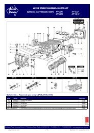
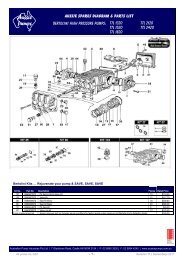
AUSSIE BLASTER PRESSURE SETTING INSTRUCTIONSEngine drive blastersNOTE: These instructions are intended for the use of Authorised <strong>Aussie</strong> Eco-Clean servicecentres only1. Connect machine to mains pressure water supply, ensuring that water is passing freely throughthe pump at the correct flow rate for specified pump by holding the gun trigger open.2. Check gun nozzle size with gauge to ensure correct nozzle size (see chart). Replace nozzle ifworn.3. Ensure machine is set up correctly for testing with two gauges, as shown above. Pressuregauge ‘A’ to be installed on top central valve cap. This gauge will measure the pump pressure.Pressure gauge ‘B’ is to be installed at the pump outlet on the delivery hose. This gauge willmeasure the in-line pressure when gun is shut off. This pressure must not exceed 20%increase on operating pump pressure. Example: 2000psi pump pressure on gauge ‘A’ withgun open: when gun is shut off gauge ‘B’ must not exceed 2400psi.4. To obtain correct pressure at pre-determined rpm:1. Remove grub screw in unloader lock ring;2. Wind down unloader until required pressure is achieved. Governor setting on engine willincrease engine rpm automatically once the engine comes under load. This will increaseengine rpm to approximately 3000rpm for Honda GX160.5. Release trigger on gun to shut off water flow and read gauge ‘B’ to determine the increase inline pressure (20% increase limit).6. If test proves OK, repeat procedure for final check.7. Unwind unloader by half a turn to ensure no pressure loss is indicated on gauge ‘A’ in pump.8. Apply Loctite 243 Super Thread to grub screw in unloader lock ring and tighten with 1.5mmallen key.9. Apply paint seal to grub screw head and thread below unloader lock ring.10. Check engine rpm and adjust throttle. Do not set engine speed higher than 3200 rpm.11. Use a 6mm nut to screw onto the throttle adjusting screw and lock tightly against the bracket.12. Apply paint seal to screw head of engine throttle adjustment screw and protruding thread behindthrottle bracket.14 <strong>Aussie</strong> <strong>Pumps</strong> <strong>Aussie</strong> Bertolini <strong>Pumps</strong> Bertolini <strong>Pumps</strong> <strong>Service</strong> <strong>Pumps</strong> Guidelines <strong>Service</strong> Guidelines – July 2011 - July 2008

![diesel fire fighting pumps PDF [261KB] - Aussie Pumps](https://img.yumpu.com/48798897/1/184x260/diesel-fire-fighting-pumps-pdf-261kb-aussie-pumps.jpg?quality=85)
![view spec sheet [pdf - 32KB] - Aussie Pumps](https://img.yumpu.com/48771802/1/184x260/view-spec-sheet-pdf-32kb-aussie-pumps.jpg?quality=85)