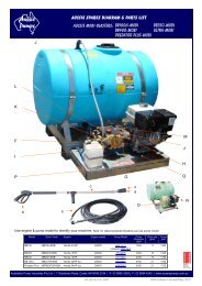
Aussie Blasters Service Fundamentals (pdf - 4.30MB) - Aussie Pumps
Aussie Blasters Service Fundamentals (pdf - 4.30MB) - Aussie Pumps
Aussie Blasters Service Fundamentals (pdf - 4.30MB) - Aussie Pumps

Create successful ePaper yourself
Turn your PDF publications into a flip-book with our unique Google optimized e-Paper software.
<strong>Aussie</strong> <strong>Blasters</strong><strong>Service</strong> <strong>Fundamentals</strong>July 2011
2 <strong>Aussie</strong> <strong>Pumps</strong> <strong>Aussie</strong> Bertolini <strong>Pumps</strong> <strong>Pumps</strong> Bertolini <strong>Service</strong> <strong>Pumps</strong> Guidelines <strong>Service</strong> – Guidelines July 2011 – July 2008
INTRODUCTIONThis manual was developed as a basic guide to understanding the operation andrequirements, installation and servicing of <strong>Aussie</strong> <strong>Pumps</strong> >Big Berty= Bertolini positivedisplacement pumps.High pressure cleaning equipment is a potentially hazardous undertaking and cancause injury and property damage. It must be installed and repaired in accordancewith the manufacturer=s instructions. Recommended OH&S safety practices must beobserved at all times.Australian Pump Industries does not assume liability or responsibility for the design oroperation of a customer=s high pressure system.CONTENTSIntroduction ..................................................................................................................................3Typical operation and requirement .....................................................................................4Pressure....................................................................................................................4Flow ..........................................................................................................................4Detergent Injection....................................................................................................4Hot water/steam systems..........................................................................................3Designing your system.........................................................................................................5Pump selection..........................................................................................................5Motor/engine selection ..............................................................................................5Spray tip selection guide......................................................................................................6Determining spray tip size.........................................................................................6Drive System .......................................................................................................................6Other components ...............................................................................................................7Inlet side components ...............................................................................................8Outlet side components ............................................................................................8Installation of components ...................................................................................................8Troubleshooting ...................................................................................................................9<strong>Service</strong> guidelines..............................................................................................................10Valve assemblies ....................................................................................................10Removing manifold head ........................................................................................10Replacing plungers .................................................................................................11Replacing V-packings .............................................................................................12Pressure cleaner test set ........................................................................................13Pressure setting instructions - engine drive.....................................................14- electric drive ....................................................15Change up to Big Berty- the Quality Change Out<strong>Aussie</strong> <strong>Aussie</strong> <strong>Pumps</strong> <strong>Pumps</strong> Bertolini Bertolini <strong>Pumps</strong> <strong>Pumps</strong> <strong>Service</strong> <strong>Service</strong> Guidelines – July – July 2011 2008 3
TYPICAL OPERATION AND REQUIREMENTSPressureThe pressure produced in a pressure washersystem is the result of forcing a known volumeof water through a known orifice size (spray tip).This pressure is measured in bar or pounds persquare inch (psi).FlowIn a pressure washer system the flow producedis determined by the speed that the pump shaftis rotated (rpm). The faster the shaft is rotatedthe higher the output volume. This water flow ismeasured in litres per minute.Nozzle OrificeSetting unloader valves for the requiredpressure of the machine depends entirely on thecorrect nozzle selection. The correct nozzleorifice can be selected to suit any specificpressure/flow combination using the chart onpage 5.Operators should be conscious that nozzle wearwill create a drop in pressure and an apparentmalfunction of the machine. The abrasive natureof water and the subsequent wear enlarges theorifice in the nozzle. The larger the orifice, theless pressure and the more danger ofsubsequent machine malfunction throughunloader failure.Further information on this subject is covered inthe Nozzle Selection Guide section.OperationThe pump which is motor driven draws water inthrough a series of inlet check valves as theplungers move back. As the plungers moveforward the inlet valves close, forcing the waterto travel through a series of outlet check valvesand to the pump outlet.When the water exits the pump the direction offlow is controlled by means of an unloader orregulating valve. A positive displacement pumpis always delivering a certain volume of waterwhether the spray outlet is open or closed so adevice is needed to control the direction of flow.This device allows the spray to exit through thespray gun or redirecting (by-passing) the flowback to the inlet of the pump if the gun is closed.As a safety device at least one pressure reliefvalve must be installed in the outbound side ofthe pump to protect against component failureand the development of dangerously highpressure.Note: Failure to install correct unloader valve orregulator device could result in serious injury andproperty damage.Chemical injectionCleaning chemicals or detergents may beintroduced into either the inbound or outboundflow of water. An inbound chemical injector usesthe pump=s ability to draw or suck fluid in tointroduce a chemical into the water flow. Anupstream injector allows chemicals to be appliedto the surface to be cleaned at normal high waterpressures. As any chemicals introducedupstream pass through the pump body, care mustbe taken to ensure the chemicals are compatiblewith the pump=s construction material andcomponents, such as seals.An outbound or downstream type of chemicalinjector uses the venturi system to draw chemicalinto the water stream. This type of injectorrequires low pressure to activate chemical flow.Low pressure is achieved by enlarging the outletorifice by changing to a larger spray tip or by anadjustable nozzle.There are advantages to using a downstreaminjector:1. Fewer pump component parts are exposed tothe cleaning chemicals which may extendsystem life.2. The operator can control the flow of chemicalsby changing the system pressure at thenozzle.3. Applying the chemical at lower pressure ismore economical as less chemical bounces offthe work surface.Hot water/steam cleanersHeated pressure washers and steam cleanersincrease the ability of high pressure water flow tobreak down dirt and grease. The cleaning actionof most detergents is also increased. Unitsincorporating a boiler are very complex andpotentially more hazardous than cold watersystems. Design of these systems requires manymore additional components and should bedesigned by qualified professionals with athorough knowledge of fuels, heat transfers, etc.4<strong>Aussie</strong> <strong>Aussie</strong> <strong>Pumps</strong> <strong>Pumps</strong> Bertolini Bertolini <strong>Pumps</strong> <strong>Pumps</strong> <strong>Service</strong> <strong>Service</strong> Guidelines Guidelines – July – 2011 July 2008
TYPICAL PRESSURE WASHER SYSTEMDESIGNING YOUR SYSTEMPump selectionThe heart of any pressure washer system isyour <strong>Aussie</strong> <strong>Pumps</strong> >Big Berty= Bertolini pump.Choose the pump that=s right for your workdemands. Higher pressure is not necessarilybest. To much pressure and flow will causeunnecessary wear on your pressure system.In addition, damage to the objects andsurfaces to be cleaned could result.Never exceed the maximum pressures orrotation speed stated in the Technical Data.Motor/engine SelectionThe size of the motor required is determinedby the flow (litres/minute) and the pressure(bar/psi) desired.Ensure that a petrol engine runs fast enough tosupply the required horsepower but do notexceed the engine manufacturer=sspecifications.Consult pump and engine manufacturer=stechnical guidelines.Refer to the Technical Data for the correct rpmrequired.DRIVE SYSTEMThere are three common methods of driving orconnecting the pump and motor/engine. Directdrive and gear reduction drive require specialcomponents that are matched to the pump andto the motor/engine as well as other technicalconsiderations. The third is belt drive. Beltdrive is considered inefficient (belt slip) and canhave negative OH&S ramifications.<strong>Aussie</strong> <strong>Aussie</strong> <strong>Pumps</strong> <strong>Pumps</strong> Bertolini Bertolini <strong>Pumps</strong> <strong>Pumps</strong> <strong>Service</strong> <strong>Service</strong> Guidelines – July – July 2011 2008 5
NOZZLE SELECTION GUIDEDETERMINING SPRAY TIP SIZEAs stated earlier the outlet pressure isdetermined by ejecting a known volume ofwater through a spray tip. The size of this tip isan important factor of efficient pressure cleanerperformance. A tip that is too large mayproduce insufficient pressure. A tip that is toosmall may cause over high pressures causingdamage to the pump and other systemcomponents.Refer to the above chart to select the correctnozzle size for your application.Firstly, ascertain the output flow of your pumpfrom the technical data. Then find thepressure (psi) you require and read down thecolumn until you reach the output closest toyour own pump. The correct spray tip for theresult you require must not exceed 90% of thehigh flow.Example: 2030 psi at 11 litres per minute,calculate 90% of flow value = 035 nozzle.<strong>Aussie</strong> Laser Tip Nozzles are available invarious sizes and spray angles. It is advisableto keep a selection different sized and angledspray tips handy for different cleaningapplications.Nozzles are also available with an adjustablespray angle (see <strong>Aussie</strong> >Vario-Zoom= nozzlesfor domestic and commercial pressurecleaners.Big Berties are Bonza!6<strong>Aussie</strong> <strong>Aussie</strong> <strong>Pumps</strong> <strong>Pumps</strong> Bertolini Bertolini <strong>Pumps</strong> <strong>Pumps</strong> <strong>Service</strong> <strong>Service</strong> Guidelines Guidelines – July – 2011 July 2008
SELECTING REMAINING COMPONENTInlet side componentsInlet filter - It is important to install a water filteron the intake line to remove and impurities orsolids in the water. This will increase theoperating life of your system and reduceproblems.A 60-120 mesh screen filter is recommended tostop foreign matter clogging valves and orifices,scratching internals, abrading packing andwearing the components.By-pass provision - The unloader valve orregulator redirects the water flow back into thepump if the orifice is closed, i.e. the gun triggeris released. An inlet water holding tank must beinstalled to accept this redirected flow.Thermal relief valve - This is a device which istemperature operated. The sensor opens thevalve and dumps water when a predeterminedtemperature is reached. Water recirculated bythe unloader valve will heat up after a certaintime and if this over heated water passesthrough the pump it may damage the pump=sinternals necessitating costly repairs.Upstream detergent injector - This deviceuses the pump to introduce the detergent intothe water stream before it enters the pump.This type of injector is not recommended forharsh or corrosive chemicals as passagethrough the pump may damage internalcomponents.Pressure reducing valve - If the water supplyentering the pump is above the maximum inletpressure specified in the Technical Data apressure reducing valve must be installed forproper and safe pump operation.Check valve - A check valve is installed toprevent any chemicals or detergents beingback-flushed into the water supply. Local watersupply authority regulations must be observed.An alternative to a check valve is the use of aholding tank to collect any back flush. Ensurethat you do not exceed the negative pressurerating of the pump.BIG BERTIES BOUNCE THE OTHERS!Outlet side componentsUnloader or regulator valve - This deviceprevents a build up of water pressure in thesystem. It is necessary for operator safety andfor system protection. When the gun is openedthe water is allowed to flow into the outlet hose.If the gun is closed the water flow is directedback into the inlet side of the pump. Installationof unloader valves must be carried out strictly inaccordance with the manufacturer=s instructions.It should be checked and serviced regularly.The unloader valve should be mounted as closeto the pump outlet as possible. Do not use anyhose between the unloader valve and the pumpoutlet.Pressure relief valve - This valve prevents adangerous build up of pressure in the system. Itis necessary for operator safety and for systemprotection. This valve will open and dump waterif the system becomes over pressurized due toany component failure.Installation of pressure relief valves must becarried out strictly in accordance with themanufacturer=s instructions and should bechecked and serviced regularly.Pulsation dampener - This device smoothspulsations caused by the pump itself and toabsorb pressure spikes when the gun is closedsuddenly. A duplex pump may require apulsation dampener because of pulsation notexperienced in a triplex pump. Long runs ofhose may generate a hammer effect which apulsation dampener may soften or prevent.Pressure gauge - This displays the operatingpressure and not only allows the operator todetermine peak performance, but also mayindicate any deficiencies occurring within thesystem. For instance, a decrease in systempressure may indicated a worn spray tip; anincrease in pressure may suggest a blockage inthe system or a faulty unloader valve.Select a gauge that is:- liquid filled to absorb pressure fluctations;- installed with a restriction orifice to avoidpressure spike damage;- appropriate for your system=s normal pressurerange.<strong>Aussie</strong> <strong>Aussie</strong> <strong>Pumps</strong> <strong>Pumps</strong> Bertolini Bertolini <strong>Pumps</strong> <strong>Pumps</strong> <strong>Service</strong> <strong>Service</strong> Guidelines – July – July 2011 2008 7
TROUBLESHOOTINGPROBLEM CAUSE REMEDYPulsation Faulty pulsation damper Check precharge, if low recharge or replaceLow pressurePump runs extremely rough, pressure very lowWater leakage from under manifold, slightleakageOil leak between crankcase and pumpingsectionOil leaking in the area of crankshaftExcessive play in the end of the crankshaftpulleyWater in crankcaseWorn nozzleBelt slippageAir leak in inlet plumbingRelief valve stuck, partially plugged or improperlyadjusted valve seat wornInlet suction strainer clogged or improperly sizedWorn packing. Abrasives in pumped fluid or severecavitation. Inadequate waterFouled or dirty inlet or discharge valvesWorn inlet, discharge valve blocked or dirtyLeaky discharge hoseCracked pistons as a result of dry runningRestricted inlet or air entering the inlet plumbingInlet restrictions and/or air leaks. Stuck inlet ordischarge valveWorn packingWorn crankcase piston rod seals, O-rings onplunger retainer wornWorn crankshaft seal or improperly installed oilseal o-ringFaulty bearingTravel plug in use on pumpWorn main bearing from excessive tension on drivebeltHumid air condensing into water inside thecrankcaseWorn packing and/or piston rod sleeve. O-rings onplunger retainer wornReplace nozzleTighten or replaceDisassemble, reseal and reassembleClean, adjust relief valve, check for worn anddirty valve seats. Kit availableClean. Check more frequentlyInstall proper filter. Suction at inlet manifoldmust be limited to less than 6m lift or 8.5psiClean inlet and discharge valve assembliesReplace worn valves, valve seats.Replace worn valves, valve seats and/ordischarge hoseReplace pistonsCheck inlet plumbing size. Check seals are airtightReplace worn cup or cups, clean out foreignmaterial, replace worn valves.Install new packingOil leaking from underside of crankcase Worn crankcase piston rod seals Replace sealsOil leaking at rear portion of the crankcaseLoud knocking noise in pumpFrequent or premature failure of the packingDamaged crankcase, rear cover o-ring, drain plugo-ring or sight glass o-ringPulley loose on crankshaftBroken or worn bearingScored, damaged or worn plungerOverpressure to inlet manifoldAbrasive material in fluid being pumpedExcessive pressure and/or temperature of fluidbeing pumpedOver pressure of pumpRunning pump dryReplace crankcase piston rod seals. Replace o-rings.Remove oil seal retainer and replace damaged o-ring and/or sealsReplace bearingReplace with breather plugReplace crankcase bearing and/or tension drivebeltChange oil more frequently. Use high gradeautomotive 30 weight nondetergent oilReplace packing. Replace o-ringsReplace cover o-ring, drain plug o-ring, or sightglass o-ringCheck key and tighten set screwReplace bearingReplace plungersReduce inlet pressureInstall proper filtration on pump inlet plumbingCheck pressures and fluid inlet temperature,ensure they are within specified rangeReduce pressureDo not run pump without water<strong>Aussie</strong> <strong>Aussie</strong> <strong>Pumps</strong> <strong>Pumps</strong> Bertolini Bertolini <strong>Pumps</strong> <strong>Pumps</strong> <strong>Service</strong> <strong>Service</strong> Guidelines – July – July 2011 2008 9
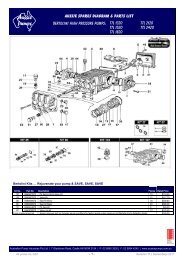
SERVICE INFORMATIONVALVE ASSEMBLIES• All inlet and discharge valves can be servicedwithout disrupting the inlet or discharge plumbing.The inlet and discharge valves are identical in allmodels.• To service any valve remove valve cap and extractvalve assembly.• Examine o-rings and replace if there is anyevidence of cuts, abrasions or distortion.• Remove valve assembly (retainer, spring, valve,valve seat) from valve cavity.• Only one <strong>Aussie</strong> <strong>Pumps</strong> valve kit is required torepair all valves in the pump. The kit contains o-rings, valve seats, poppets, springs and retainers.• Install new o-ring in valve cavity.• Insert assembly into valve cavity.• Replace valve cap and torque to specifications.REMOVING MANIFOLD HEAD• Remove the fasteners retaining head• Separate head from crankcase. It may benecessary to tap head lightly with soft mallet toloosed. Care should be taken not to damageplungers when sliding head from crankcase.• The V-packing assemblies may come off withthe head. Examine plungers. The surfaceshould be smooth and free from scoring andpitting. If not, replace.• Replace manifold head and torque tospecifications using the sequence shown below:TORQUE SEQUENCE FOR TIGHTENING HEADInstall all head bolts fingertight. Torque to 14 Nm insequence as shown, then retorque to specificationsfollowing the same sequence10<strong>Aussie</strong> <strong>Aussie</strong> <strong>Pumps</strong> <strong>Pumps</strong> Bertolini Bertolini <strong>Pumps</strong> <strong>Pumps</strong> <strong>Service</strong> <strong>Service</strong> Guidelines Guidelines – July - 2011 February 2003
SERVICE INFORMATIONREPLACING PLUNGERS•Remove stainless steel piston nut andcopper washer from piston rod• If slinger washer comes off withplunger ensure this is replaced beforethe new plunger is installed.• Separate piston from plunger• Install new o-ring and teflon backup ring onplunger.• A thin film of grease on the outside of the o-ringswill ensure a better seal.• Carefully press piston over plunger• Fit new copper washer to the piston guidesand torque to specificationsTYPICAL PACKING ASSEMBLYUnique BertoliniDouble SealO-ringFemale adaptorV-packingMale adaptor head ringIntermediate ringLong life ringV-packingHead ring<strong>Aussie</strong> <strong>Pumps</strong> Bertolini <strong>Pumps</strong> <strong>Service</strong> Guidelines – July - February 2011 2003 11
SERVICE INFORMATIONREPLACING V-PACKINGS• Remove manifold from crankcase• Insert proper extractor collet through main sealretainer. Tighten collet and extract retainers,v-packings and head rings.• Place correct insertion tool in cylinderand install front head ring, v-packingand long life ring and press firmly intocylinder until they will go no further.• Insert intermediate seal retainer pressing itfirmly into cylinder until it will go no furtherusing proper insertion tool.• Install rear head ring v-packing and mainseal retainer into cylinder in order shown andpress firmly into cylinder• Repeat this sequence for each cylinder• Coat each plunger with grease and carefullyremount manifold. Torque head tospecifications.12 <strong>Aussie</strong> <strong>Pumps</strong> <strong>Aussie</strong> Bertolini <strong>Pumps</strong> Bertolini <strong>Pumps</strong> <strong>Service</strong> <strong>Pumps</strong> <strong>Service</strong> Guidelines Guidelines – July 2011 - July 2008
AUSSIE WATER BLASTERS RECOMMENDED PUMP OILSIt is recommended that the following oils be used:APPLICATION AUSSIE BLASTER RECOMMENDED OILAxial style wobble-plate pumpsH101H110H120H130F140F150F180PantherCougarTiger MkIIRenolin 100B non-foamingoilTriplex style crankshaft/pistonpumpsMonsoon SeriesAB SeriesBB SeriesSuper Indy SeriesTop Pro (TK) SeriesAdmiralTerminatorPredatorSAE 75W/90 gear oilPressure cleaner gear boxes Slow speed machines SAE 75W/90 gear oilAUSSIE PRESSURE CLEANER TEST SETEverybody knows that professional pressure cleaners occasionally need to have their pressuretested and sometimes reset. Doing this efficiently,and in line with our professionalrecommendations (see pages 13 and 14) is noteasy unless you have the right equipment.Checking pressure regularly will tell you if nozzlesare worn, if the pressure regulator is worn, if thereare leaks in the system, if the valves are stickingand signal other problems that can manifestthemselves in low pressure operation.The new <strong>Aussie</strong> “Part number ATESTSET/<strong>Aussie</strong>test set up” will solve those problems. Consistingof a convenient brass T with M22 quick couplerand 6000 psi pressure gauge you can check tomake sure everything is operating as it should.Detailed instructions are included with each kit.<strong>Aussie</strong> <strong>Aussie</strong> <strong>Pumps</strong> Bertolini <strong>Pumps</strong> <strong>Pumps</strong> <strong>Service</strong> Guidelines – July - July 2011 2008 13
AUSSIE BLASTER PRESSURE SETTING INSTRUCTIONSEngine drive blastersNOTE: These instructions are intended for the use of Authorised <strong>Aussie</strong> Eco-Clean servicecentres only1. Connect machine to mains pressure water supply, ensuring that water is passing freely throughthe pump at the correct flow rate for specified pump by holding the gun trigger open.2. Check gun nozzle size with gauge to ensure correct nozzle size (see chart). Replace nozzle ifworn.3. Ensure machine is set up correctly for testing with two gauges, as shown above. Pressuregauge ‘A’ to be installed on top central valve cap. This gauge will measure the pump pressure.Pressure gauge ‘B’ is to be installed at the pump outlet on the delivery hose. This gauge willmeasure the in-line pressure when gun is shut off. This pressure must not exceed 20%increase on operating pump pressure. Example: 2000psi pump pressure on gauge ‘A’ withgun open: when gun is shut off gauge ‘B’ must not exceed 2400psi.4. To obtain correct pressure at pre-determined rpm:1. Remove grub screw in unloader lock ring;2. Wind down unloader until required pressure is achieved. Governor setting on engine willincrease engine rpm automatically once the engine comes under load. This will increaseengine rpm to approximately 3000rpm for Honda GX160.5. Release trigger on gun to shut off water flow and read gauge ‘B’ to determine the increase inline pressure (20% increase limit).6. If test proves OK, repeat procedure for final check.7. Unwind unloader by half a turn to ensure no pressure loss is indicated on gauge ‘A’ in pump.8. Apply Loctite 243 Super Thread to grub screw in unloader lock ring and tighten with 1.5mmallen key.9. Apply paint seal to grub screw head and thread below unloader lock ring.10. Check engine rpm and adjust throttle. Do not set engine speed higher than 3200 rpm.11. Use a 6mm nut to screw onto the throttle adjusting screw and lock tightly against the bracket.12. Apply paint seal to screw head of engine throttle adjustment screw and protruding thread behindthrottle bracket.14 <strong>Aussie</strong> <strong>Pumps</strong> <strong>Aussie</strong> Bertolini <strong>Pumps</strong> Bertolini <strong>Pumps</strong> <strong>Service</strong> <strong>Pumps</strong> Guidelines <strong>Service</strong> Guidelines – July 2011 - July 2008
AUSSIE BLASTER PRESSURE SETTING INSTRUCTIONSElectric drive blastersNOTE: These instructions are intended for the use of Authorised <strong>Aussie</strong> Eco-Clean servicecentres only1. Connect machine to mains pressure water supply, ensuring that water is passing freely throughthe pump at the correct flow rate for specified pump by holding the gun trigger open.2. Check gun nozzle size with gauge to ensure correct nozzle size (see chart). Replace nozzle ifworn.3. Ensure machine is set up correctly for testing with two gauges, as shown above. Pressuregauge ‘A’ to be installed on top central valve cap. This gauge will measure the pumppressure.Pressure gauge ‘B’ is to be installed at the pump outlet on the delivery hose. Thisgauge will measure the in-line pressure when gun is shut off. This pressure must not exceed20% increase on operating pump pressure. Example: 2000psi pump pressure on gauge ‘A’with gun open: when gun is shut off gauge ‘B’ must not exceed 2400psi.Measure amps on power supply cable to make sure amps are running at acceptable levels whendesired pump performance is obtained.4. To obtain correct pressure at pre-determined rpm:1. Remove grub screw in unloader lock ring;2. Wind down unloader until required pressure is achieved. Check amp meter to ensureelectrical characteristics are within acceptable parameters.5. Release trigger on gun to shut off water flow and read gauge ‘B’ to determine the increase in linepressure (20% increase limit).6. If test proves OK, repeat procedure for final check.7. Unwind unloader by half a turn to ensure no pressure loss is indicated on gauge ‘A’ in pump.8. Apply Loctite 243 Super Thread to grub screw in unloader lock ring and tighten with 1.5mm allenkey.9. Apply paint seal to grub screw head and thread below unloader lock ring.<strong>Aussie</strong> <strong>Aussie</strong> <strong>Pumps</strong> <strong>Pumps</strong> Bertolini Bertolini <strong>Pumps</strong> <strong>Pumps</strong> <strong>Service</strong> <strong>Service</strong> Guidelines Guidelines – July - July 2011200815
PREVENTATIVE MAINTENANCEPrevent pump failureAvoid costly repairsMinimise downtimeSimple steps in preventative maintenance will allow you to get the best out of your machinery:DAILY CHECK LIST1. Check pump and gearbox oil level2. Check engine oil level3. Check nozzle wear4. Check all high pressure components for leaks:a) gun/lance b) high pressure hose c) all fittings.5. Check water filter and clean if necessary6. Check unloader, safety valve and thermal dump for leaks.THREE MONTHLY REGULAR SERVICEAll professional machines need to be thoroughly serviced every three months. The service involvedshould include the engine manufacturer’s recommendations, where applicable, (see separate EngineManual) and the following:1. Change pump oil2. Change gearbox oil3. Check filter for foreign debris4. Check unloader, safety valve and thermal dump for leaks5. Check all high pressure components for leaks:a) gun/lance b) high pressure hose c) all fittings6. Replace nozzles7. Check gearbox to engine key for wear. If the key is worn, see your local <strong>Aussie</strong> Eco-Cleanservice agent for instructions on rectification or contact <strong>Aussie</strong> Eco-Clean <strong>Service</strong> Department.LOOK AFTER YOUR MACHINE AND IT WILL LOOK AFTER YOU!AND REMEMBER . . .Always wear protective clothing,including boots and goggles!RELIABLE PRODUCTS . . . RELIABLE PEOPLEAUSTRALIAN PUMP INDUSTRIES PTY LTDACN 061 619 2347 Gladstone Rd, Castle Hill NSW 2154. PO Box 6164, BHBC NSW 2153Ph 02 9894 4144 Fx 02 9894 4240 email: wlorenz@aussiepumps.com.auwww.aussiepumps.com.au16 <strong>Aussie</strong> <strong>Pumps</strong> <strong>Aussie</strong> Bertolini <strong>Pumps</strong> Bertolini <strong>Pumps</strong> <strong>Service</strong> <strong>Pumps</strong> Guidelines <strong>Service</strong> Guidelines – July 2011 - July 2008

![diesel fire fighting pumps PDF [261KB] - Aussie Pumps](https://img.yumpu.com/48798897/1/184x260/diesel-fire-fighting-pumps-pdf-261kb-aussie-pumps.jpg?quality=85)
![view spec sheet [pdf - 32KB] - Aussie Pumps](https://img.yumpu.com/48771802/1/184x260/view-spec-sheet-pdf-32kb-aussie-pumps.jpg?quality=85)