

Disc Ceramic Capacitors - IBS Electronics
Disc Ceramic Capacitors - IBS Electronics
Disc Ceramic Capacitors - IBS Electronics

You also want an ePaper? Increase the reach of your titles
YUMPU automatically turns print PDFs into web optimized ePapers that Google loves.
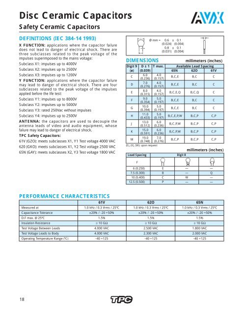
<strong>Disc</strong> <strong>Ceramic</strong> <strong>Capacitors</strong>Safety <strong>Ceramic</strong> <strong>Capacitors</strong>DEFINITIONS (IEC 384-14 1993)X FUNCTION: applications where the capacitor failuredoes not lead to danger of electrical shock. There arethree subclasses related to the peak voltage of theimpulses superimposed to the mains voltage:Subclass X1: impulses up to 4000VSubclass X2: impulses up to 2500VSubclass X3: impulses up to 1200VY FUNCTION: applications where the capacitor failuremay lead to danger of electrical shock. There are foursubclasses related to the peak voltage of the impulsesapplied before the life test:Subclass Y1: impulses up to 8000VSubclass Y2: impulses up to 5000VSubclass Y3: rated 250Vac without impulsesSubclass Y4: impulses up to 2500VANTENNA: the capacitors are used to decouple theantenna leads of video and audio equipment, whosefailure may lead to danger of electrical shock.TPC Safety <strong>Capacitors</strong>:61V (GZO): meets subclasses X1, Y1 Test voltage 4000 VAC620 (GKO): meets subclasses X1, Y2 Test voltage 2500 VAC65N (GAY): meets subclasses X2, Y3 Test voltage 1800 VACDIMENSIONSØ mm = 0.6 ± 0.1(0.024) (0.004)Ø mm = 0.8 ± 0.1(0.031) (0.004)millimeters (inches)Digit 9 D ± 1 T max. Available Lead Spacing(ø) (0.039) 65N 62O 61VC6.0 4.0(0.236) (0.157)B,C,E B,C CD7.0 4.0(0.276) (0.157)B,C,E B,C CE8.0 4.0(0.315) (0.157)B,C,E,Q B,C,Q CF9.0 5.0(0.354) (0.197)B,C,E B,C CG10.0 5.0(0.394) (0.197)B,C,E B,C CH11.0 5.0(0.433) (0.197)B,C,E,P,W B,C,P C,PJ13.0 6.0(0.512) (0.236)B,C,P,W B,C,P C,PK15.0 6.0(0.591) (0.236)B,C,P,W B,C,P C,PM19.0 7.0(0.748) (0.276)B,C,P B,C,P C,P(E), (X), (W): upon requestLead Spacing Digit 8millimeters (inches)F6 (0.250) E — —7.5 (0.300) B — Q10 (0.400) C W —12.5 (0.500) P — —PERFORMANCE CHARACTERISTICS61V 62O 65NMeasured at 1.0 kHz / 0.3 Vrms / 25ºC 1.0 kHz / 0.3 Vrms / 25ºC 1.0 kHz / 0.3 Vrms / 25ºCCapacitance Tolerance ±20% / -20 +50% ±20% / -20 +50% ±20% / -20 +50%D.F max. @ 25ºC 1.5% 1.5% 1.5%Insulation Resistance ≥ 10 GΩ ≥ 10 GΩ ≥ 10 GΩTest Voltage Between Leads 4.000 VAC 2.500 VAC 1.800 VACTest Voltage Leads to Body 4.000 VAC 2.300 VAC 2.000 VACOperating Temperature Range (ºC) -40 +125 -40 +125 -40 +12518
<strong>Disc</strong> <strong>Ceramic</strong> <strong>Capacitors</strong>Safety <strong>Ceramic</strong> <strong>Capacitors</strong>APPROVED LOGOSCSA IMQ SEV ULVDEBSICERTIFICATION BODY APPROVALS61V62OStandardCertificate Rated ClimaticStandardCertificate Rated ClimaticNumber Voltage Category Number Voltage CategoryUL UL 1414 E 147842 (N) 250 VAC UL 1414 E 147842 (N) 250 VACCSA CAN/CSA - C22.2 LR 100430-2 250 VAC CAN/CSA - C22.2 LR 100430-1 250 VACNo 1-94 No 1-94SEV SEV 1016 93-100959.10 400 VAC 40/085/21 SEV 1016 93-100959.12 400 VAC 40/125/21SEV 105594612 DIN VDE 0560 - part 2 76830 400 VAC 25/085/21VDE DIN EN 132400: 1995 94610 X1 : 400 VAC 40/085/21/C 76804IEC 384-14: 1993 94634 Y1 : 250 VAC DIN EN 132400: 1995 101384 X1 :400 VAC 40/085/21/CIEC 384-14: 1993Y2 : 250 VACBS EN 60065: 1994 X1 : 400 VAC BS EN 60065: 1994 X1 : 400 VACBSI IEC 384-14: 1993 228237 Y1 : 250 VAC 40/125/21/C IEC 384-14: 1993 228197 Y2 : 250 VAC 40/125/21/CBS EN 132400: 1995 BS EN 132400: 1995IMQ EN 132400: 1994 V4551 X1 : 400 VAC 40/125/21/C EN 132400: 1994 V4635 X1 : 400 VAC 40/125/21/CIEC 384-14: 1993 Y1 : 250 VAC IEC 384-14: 1993 Y2 : 250 VAC19
<strong>Disc</strong> <strong>Ceramic</strong> <strong>Capacitors</strong>Safety <strong>Ceramic</strong> <strong>Capacitors</strong> Epoxy CoatedCAPACITANCE VS. DISC DIAMETERDigits 1, 2, 3of P.N. 61V 62O 65NC R(pF)100120 6.0 (0.236) 6.0 (0.236)150220330 7.0 (0.276)3906.0 (0.236)470 7.0 (0.276)5606808.0 (0.315)82010009.0 (0.354) 8.0 (0.315)7.0 (0.276)12001500 11.0 (0.433)9.0 (0.354) 8.0 (0.315)2200 10.0 (0.394) 9.0 (0.354)3300 13.0 (0.512)11.0 (0.433)13.0 (0.512)3900 15.0 (0.591)13.0 (0.512)4700 19.0 (0.748) 15.0 (0.591)TYPICAL APPLICATION FOR SAFETY CERAMIC DISCS AND SWITCH MODEAcross the line capacitors for noise suppressionLine by-pass for noise suppressionCyCyCxCxCyCyCx=TPC 61V or 62O seriesCy=TPC 61V or 62O seriesTypical X and Y function applicationProtection and suppression of a motor(X and Y function)CxCyCyCxCyCyY FunctionChassisMY FunctionCapacitorThompson 61V or 62O seriesRX FunctionS20
<strong>Disc</strong> <strong>Ceramic</strong> <strong>Capacitors</strong>Ordering CodeHOW TO ORDER5OQ222General Purpose5A = NP0 / I*5B = P100 / I*5C = N150 / I*5D = N220 / I*5E = N330 / I*5F = N470 / I5G = N750 / I5H = N1500 / I*5I = N2200 / I*5J = N4700 / I5K = SL5M = Y5E / II5N = Y5F / II5O = Y5P / II*5P = Y5R / II*5Q = Y5T / II5S = Y5U / II5T = Y5V / II5U = Z5V / II*5V = Z4V / III5W = Y5P / III5Y = Y5U / III5Z = Y5V / III*Upon RequestProfessional Switch ModeSafety6A = NP0 / I*6B = P100 / I*6C = N150 / I*6D = N220 / I*6E = N330 / I*6F = N470 / I6G = N750 / I*6H = N1500 / I*6I = N2200 / I6J = N4700 / I61 = SAFETY62 = SAFETY65 = SAFETY67 = Y5U / SM68 = Y5V / SM6L = Y5P / SM6M = X5E / II6N = X5F / II6O = X5P / II*6P = X5R / II*6Q = X5T / II6S = X5U / II6T = X5V / II6U = Z5V / II*6V = Z4V / III6W = Y5P / III6Y = Y5U / III6Z = Y5V / IIIRated Voltage (dc)D = 16VF = 25VH = 50VK = 100VN = SAFETYO = SAFETYQ = 500VR = 1000VS = 2000VT = 3000VU = 4000VV = SAFETYW = 5000V*X = 6000V*Y = 7500VCapacitance = TPC code1 pF = 1R01.2pF = 1R21.5pF = 1R51.8pF = 1R82.2pF = 2R22.7pF = 2R73.9pF = 3R94.7pF = 4R75.6pF = 5R66.8pF = 6R88.2pF = 8R210pF = 10012pF = 12015pF = 15018pF = 18022pF = 22027pF = 27033pF = 33039pF = 39047pF = 47056pF = 56068pF = 68082pF = 820Capacitance222 = 2.2 nFCapacitance = TPC code100pF = 101120pF = 121150pF = 151180pF = 181220pF = 221270pF = 271330pF = 331390pF = 391470pF = 471560pF = 561680pF = 681820pF = 8211nF = 1021.2nF = 1221.8nF = 1822.2nF = 2222.7nF = 2723.3nF = 3323.9nF = 3924.7nF = 4725.6nF = 5626.8nF = 6828.2nF = 82210nF = 10315nF = 15322nF = 22333nF = 33347nF = 473100nF = 104200nF = 2044
<strong>Disc</strong> <strong>Ceramic</strong> <strong>Capacitors</strong>Ordering CodeMAEAAToleranceC = ±0.25 pFD = ±0.50 pFJ = ±5%K = ±10%M = ±20%S = -20+50%Z = -20+80%P = 0+100%Lead Formingmm inches2.5 ±0.5 .1 ± .025 D – –5 +0.6 -0.2.2 ± .025 A O N6 +0.6 -0.2.25 ± .025 E X –7.5+1-0.5.3 ± .05 B R Q10 +0.5 -1.0.4 ± .05 C W –12.5+1-0.5.5 ± .05 P – –Capacitor Diameter± 2 (0.079)A = 4 (0.157)B = 5 (0.197)C = 6 (0.236)D = 7 (0.276)E = 8 (0.315)F = 9 (0.354)G = 10 (0.394)H = 11 (0.433)J = 13 (0.512)K = 15 (0.591)M* = 19 (0.748)*Wire 0.8 (0.031) recommendedDiam ≤9 (0.354) andF = 5.00 (0.197)FinishingFor every other:Cardboard StripsA =PackagingBulkE = 5 (0.197) ± 1 (0.039) free wire lengthC = 10 (0.394) ± 1 (0.039) free wire lengthD = 25 (0.984) ± 1 (0.039) free wire lengthTapingReel Avisert PanasertAmmoPackH L L J L LAvisertPanasertI M M K M MCoating does notsurpass the bendA = PhenolicLow Voltage( General )PurposeQ = Waxed phenolicS = Epoxy (Professional) cap. diameter≤ 8 (0.315)D = Epoxy (Professional) cap. diameter> 8 (0.315)High VoltageF = Measuredfrom thecenter ofleadsPlease note that not all code combinationsare either possible or available.C = Epoxy wire diameterI = Epoxy wire diameterL = Phenolic wire diameter0.6±0.1(0.024) (0.004)0.8±0.1(0.031) (0.004)0.6±0.1(0.024) (0.004)5
<strong>Disc</strong> <strong>Ceramic</strong> <strong>Capacitors</strong>MarkingGeneral PurposeA = NP0 / I*B = P100 / I*C = N150 / I*D = N220 / I*E = N330 / I*F = N470 / IG = N750 / IH = N1500 / I*I = N2200 / I*J = N4700 / IK = SLM = Y5E / IIN = Y5F / IIO = Y5P / IIP = Y5R / IIQ = Y5T / IIS = Y5U / IIT = Y5V / IIU = Z5V / IIV = Z4V / III*W = Y5P / II*X = Y5R / IIY = Y5U / IIZ = Y5V / II*Upon RequestDIG. 2OTC / ClassProfessionalA = NP0 / IB = P100 / IC = N150 / ID = N220 / IE = N330 / IF = N470 / IG = N750 / IH = N1500 / II = N2200 / IJ = N4700 / I7 = Y5U / SM8 = Y5V / SML = Y5P / SMM = X5E / IIN = X5F / IIO = X5P / IIP = X5R / IIQ = X5T / IIS = X5U / IIT = X5V / IIU = Z5V / IIV = Z4V / IIIW = Y5P / IIIX = Y5R / IIIY = Y5U / IIIZ = Y5V / IIILogo: Only in diam. ≥ 6mmDIG. 3QRated VoltageD = 16VF = 25VH = 50VK = 100VQ = 500VR = 1000VS = 2000VT = 3000VU = 4000VW = 5000VX = 6000VY = 7500VTC – Temperature coefficient.DIG – for better understanding, check pages 3 and 4.222OQMDIG. 7MToleranceC = ±0.25pFD = ±0.5pFJ = ±5%K = ±10%M = ±20%S = -20 +50%Z = -20 +80%P = 0 +100%SafetyFrontCapacitanceAs aboveCapacitance1pF = 1091.2pF = 1291.5pF = 1591.8pF = 1892.2pF = 2292.7pF = 2793.9pF = 3994.7pF = 4795.6pF = 5696.8pF = 6898.2pF = 82910pF = 10012pF = 12015pF = 15018pF = 18022pF = 22027pF = 27039pF = 39047pF = 47056pF = 56068pF = 68082pF = 82061V471MEIA100pF = 101120pF = 121150pF = 151180pF = 181220pF = 221270pF = 271390pF = 391470pF = 471560pF = 561680pF = 681820pF = 8211nF = 1021.2nF = 1221.8nF = 1822.2nF = 2222.7nF = 2723.9nF = 3924.7nF = 4725.6nF = 5626.8nF = 6828.2nF = 82210nF = 10315nF = 15322nF = 22333nF = 33347nF = 473100nF = 104200nF = 204Type61V62065NToleranceAs aboveBack: (Approval marks)28
<strong>Disc</strong> <strong>Ceramic</strong> <strong>Capacitors</strong>PackagingIDENTIFICATION AND TRACEABILITYOn all TPC ceramic capacitorspackages, you will find a bar code labelwith the following information:Lot numberManufacturing dateQuantity of parts per packagingProduct part numberTAPED PARTS QUANTITY TABLEmillimeters (inches)Rated Voltage Diameter Quantities(Vr) D Ammopack ReelVr
<strong>Disc</strong> <strong>Ceramic</strong> <strong>Capacitors</strong>Tape and Reel SpecificationsThere are two types of taped disc ceramic capacitors:Straight or crimped leads.Both types can be shipped on reels or ammopack.The standard packaging quantities are shown bellow:Fig. 1 Fig. 2 Fig. 3Straight leadsmillimeters (inches)Crimped leadsMaximum pull force during insertion and lead cutF 1F 24 (0.157) ≤ D < 6 (0.236) 12N 20ND ≥ 6 (0.236) 20N 25NDigit 11 Available Tapings Digit 9LMSizes 4 (0.157) ≤ D ≤ 11 (0.433) A... HJ HK ISizes 6 (0.236) ≤ D ≤ 11 (0.433) C... HTPC Code Digit 11Packaging Avisert PanasertReelHFIGURE 1LFIGURE 2LFIGURE 3JFIGURE 1LFIGURE 2LFIGURE 3AmmopackIFIGURE 1MFIGURE 2MFIGURE 3KFIGURE 1MFIGURE 2MFIGURE 3Figure 2: Inside Crimp 100V... 1000VFigure 3: Outside Crimp 1000V30
<strong>Disc</strong> <strong>Ceramic</strong> <strong>Capacitors</strong>Tape and Reel SpecificationsStraight LeadsCrimpedFigure 1 Figure 2 & 3Description of Symbols A (Avisert) P (Panasert) Avisert & PanasertCrimp angle ∝ — — 20º...45ºCrimp length C — — 1.7 min.Lead diameter d 0.60 ± 0.1<strong>Disc</strong> diameter D 11 max.Lead hole diameter Do 4.0 ± 0.2<strong>Disc</strong> thickness T See CatalogLead spacing F 5.0Component alignment, front-rear ∆ h 0 ± 1Height of component from tape center H 19.5 ± 0.5 16.5 ± 0.5 - 0 —Height from tape center to crimp Ho — — 16 + 0.5 - 0Component height H1 32.25 max.>23.5


