HiRel Space Guide (Rev. A)
HiRel Space Guide (Rev. A)
HiRel Space Guide (Rev. A)

Create successful ePaper yourself
Turn your PDF publications into a flip-book with our unique Google optimized e-Paper software.
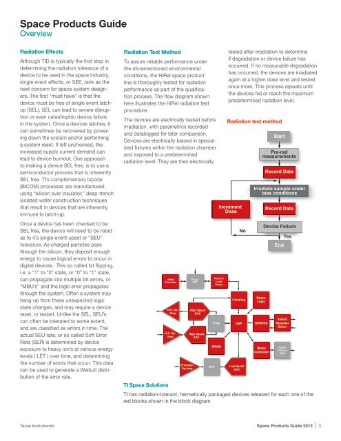
<strong>Space</strong> Products <strong>Guide</strong>OverviewRadiation EffectsAlthough TID is typically the first step indetermining the radiation tolerance of adevice to be used in the space industry,single event effects, or SEE, rank as thenext concern for space system designers.The first “must have” is that thedevice must be free of single event latchup(SEL). SEL can lead to severe disruptionor even catastrophic device failurein the system. Once a devices latches, itcan sometimes be recovered by poweringdown the system and/or performinga system reset. If left unchecked, theincreased supply current demand canlead to device burnout. One approachto making a device SEL free, is to use asemiconductor process that is inherentlySEL free. TI’s complementary bipolar(BiCOM) processes are manufacturedusing “silicon over insulator,” deep-trenchisolated wafer construction techniquesthat result in devices that are inherentlyimmune to latch-up.Once a device has been checked to beSEL free, the device will need to be ratedas to it’s single event upset or “SEU”tolerance. As charged particles passthrough the silicon, they deposit enoughenergy to cause logical errors to occur indigital devices. This so called bit flipping,i.e. a “1” to “0” state, or “0” to “1” state,can propagate into multiple bit errors, or“MBU’s” and the logic error propagatesthrough the system. Often a system mayhang-up from these unexpected logicstate changes, and may require a devicereset, or restart. Unlike the SEL, SEU’scan often be tolerated to some extent,and are classified as errors in time. Theactual SEU rate, or so called Soft ErrorRate (SER) is determined by deviceexposure to heavy ion’s at various energylevels ( LET ) over time, and determiningthe number of errors that occur. This datacan be used to generate a Weibull distributionof the error rate.Radiation Test MethodTo assure reliable performance underthe aforementioned environmentalconditions, the <strong>HiRel</strong> space productline is thoroughly tested for radiationperformance as part of the qualificationprocess. The flow diagram shownhere illustrates the <strong>HiRel</strong> radiation testprocedure.The devices are electrically tested beforeirradiation, with parametrics recordedand datalogged for later comparison.Devices are electrically biased in specializedfixtures within the radiation chamberand exposed to a predeterminedradiation level. They are then electricallyPWMControllerH.S. Op-AmpH.S. Op-AmpPrecisionOp-AmpPowerFETHigh SpeedDACHigh SpeedADCMUXRadiation test methodIncrementDosePoint ofLoadPowerFPGASRAMtested after irradiation to determineif degradation or device failure hasoccurred. If no measurable degradationhas occurred, the devices are irradiatedagain at a higher dose level and testedonce more. This process repeats untilthe devices fail or reach the maximumpredetermined radiation level.NoClockingDSPLow SpeedADCStartPre-radmeasurementsRecord DataIrradiate sample underbias conditions<strong>Space</strong>LogicSERDESMotorControllerRecord DataDevice FailureEndYesSwitchRepeaterDriverPowerFETs orBITsTI <strong>Space</strong> SolutionsTI has radiation-tolerant, hermetically packaged devices released for each one of thered blocks shown in the block diagram.Texas Instruments <strong>Space</strong> Products <strong>Guide</strong> 2013 | 3