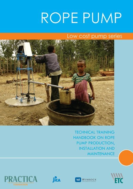
ROPE PUMP - Practica Foundation
ROPE PUMP - Practica Foundation
ROPE PUMP - Practica Foundation

You also want an ePaper? Increase the reach of your titles
YUMPU automatically turns print PDFs into web optimized ePapers that Google loves.
<strong>ROPE</strong> <strong>PUMP</strong>Low cost pump seriesTECHNICAL TRAININGHANDBOOK ON <strong>ROPE</strong><strong>PUMP</strong> PRODUCTION,INSTALLATION ANDMAINTENANCE
Rope pump manualTECHNICAL TRAINING HANDBOOK ON<strong>ROPE</strong> <strong>PUMP</strong> PRODUCTION,INSTALLATION AND MAINTENANCEPublished by the PRACTICA <strong>Foundation</strong>Authors – Jan Nederstigt, Arjen van der WalTechnical drawings – Erik den Toom, Rob DeddenPhotos – PRACTICA <strong>Foundation</strong>Illustrations – Ron Offerman / TekenteamLayout – Marijke Kreikamp / 4colour designFirst edition – March 2006Second edition – January 2010; drawing updateThird edition – August 2011PRACTICA <strong>Foundation</strong> develops and disseminates low-cost appropriate technology in water and renewable energy indeveloping countries. We focus on technology that responds to local cultural contexts, can be locally produced andmaintained, and supports existing markets.PRACTICA <strong>Foundation</strong>Oosteind 47 - NL-3356 AB Papendrecht - The Netherlands(t) +31(0)786150125info@practica.orgwww.practicaPRACTICA <strong>Foundation</strong> - <strong>ROPE</strong> <strong>PUMP</strong> Manual
Table of contentsModule 1THE <strong>ROPE</strong> <strong>PUMP</strong>Module 2INSTALLATION ANDMAINTENANCE1. The rope pump as a low-cost familyhandpump2. What organizations must know3. Getting started / the rope pump as abusinessThis module creates awareness on the technologyand applicability of the rope pump as a family waterpump and provides a road-map for implementation. Itis meant for NGO’s, governments and implementingorganisations considering the implementation of a ropepump production and installation project.1. What installer must know2. How to install a rope pump3. How to maintain your pumpModule 2 describes the installation and maintenanceprocedures of the rope pump. This module is a step-bystepexplanation that makes use of cartoons to illustratethe process. It is designed to be used by technical staffresponsible for installation of the pump and training ofthe users in operation and maintenance of the pump.257101427Module 31. Parts and materials list2. Workshop equipment and tools3. Steps of production4. Rope pump production drawings5. Welding jigs production drawings282930PRODUCTIONModule 3 describes the detailed steps of productionof the rope pump including illustrations of production.The production steps refer to the production drawings,making use of the appropriate welding jigs, of which thedrawings are included. This module is designed to beused by rope pump production enterprises as well as aguide for production training courses.PRACTICA <strong>Foundation</strong> - <strong>ROPE</strong> <strong>PUMP</strong> Manual
PRACTICA <strong>Foundation</strong> - <strong>ROPE</strong> <strong>PUMP</strong> Manual
<strong>ROPE</strong> <strong>PUMP</strong>Module 1THE <strong>ROPE</strong> <strong>PUMP</strong>
<strong>ROPE</strong> <strong>PUMP</strong> - Module 1 - The <strong>ROPE</strong> <strong>PUMP</strong>1. THE <strong>ROPE</strong> <strong>PUMP</strong> AS A LOW-COST FAMILY HAND<strong>PUMP</strong><strong>PUMP</strong>ING WATER BY HANDDrinking water handpumps are devices that use manualpower to pump groundwater to the surface. There is a fullrange of different pumps available on the market, varyingin pumping mechanism, depth range, price, quality, etc.For selection of the best handpump for a specific situation,major selection criteria are:- Water table; distinguishing between suction handpumps(0m to 7m) and lift handpumps (7m – 80m) with the typeof lift pump again depending on the actual water table;- Type of water source; pumping from a dug well, a tubewell / bore hole or from surface water;- Number of pump users; community handpumps versusfamily pumps;- Local standards and norms;- Desired system of operation and maintenanceand convenient for both female and male users ofdifferent ages;- Easy maintenance; regular maintenance only involvesweekly lubrication of the rotating parts and tensioningof the rope, which does not require specific skills;- Simple repairs; most repairs on the pump can be doneby the users themselves or by a village level mechanic;- Local production; the pump is designed in such a waythat it can be produced by small workshops with basicskills in metal works, avoiding difficult importation ofpumps or spare parts;Other characteristics of the rope pump make it less suitablefor use in specific situation. Those include:- Open structure; at the discharge and return tube, thepump is open to the air and contamination of the ropeis possible via contact by hand;- Free outflow; due to the design of the rope pump, it isnot possible to build up pressure on the delivery side,which makes the pump unsuitable to pump water tooverhead tanks;- No foot valve; each time when starting to pump, theraising main needs to be filled with water before waterstarts to flow. Especially for deeper wells, this takesextra effort;The summarized performance figures of the rope pump areas follows:CHARACTERISTICS OF THE <strong>ROPE</strong> <strong>PUMP</strong>The rope pump or rope and washer pump is a lift handpumpthat combines a number of characteristics that makes thepump very suitable for fetching drinking water for smallgroups of users (family level) for water depths up to 35m.Those characteristics include:- Low cost; due to the simple design and choice ofmaterials and production methods, the productioncosts of the rope pump are low compared to otherhandpumps;- Understandable technology; all parts of the pump arevisible and the operation of the pump can be easilyunderstood by producers, technicians and users;- User-friendly; pumping by turning a handle is a simpleDischarge @10m 35 l/min@20m@35mMaximum depthInput powerOutput levelBorehole diameterminimumApplicationCosts20 l/min10 l/min35 m50W approx.1 m above ground level75mm (or 3*)1-10 houselholds(up to to 50 users total)€50 – € 150 approximately(based on model and country ofproduction)*based on an input power of 50W, which is the humanpower output that women and children can deliver for longerperiods of time.2PRACTICA <strong>Foundation</strong> - <strong>ROPE</strong> <strong>PUMP</strong> Manual
<strong>ROPE</strong> <strong>PUMP</strong> - Module 1 - The <strong>ROPE</strong> <strong>PUMP</strong>HOW THE <strong>PUMP</strong> WORKSThe Rope pump consists of a wheel and an endless ropewith small pistons, made of polyethylene or rubber that areattached to the rope at intervals of 1 meter. The pistons fitin the PVC pipe (called ‘rising main’) with a clearance of1mm. The rope and pistons move freely down into the well.At the bottom, the rope is guided by a turning point (called‘guide box’) into the rising main. The wheel and handle areattached to a rotating shaft mounted on a support structureon top of the well. The rope and pistons are moved byturning the wheel. The water is lifted by the pistons anddischarged at the surface.The Rope pump is a pump with a constant output, unlike thepulsating flow of piston pumps. The weight of the watercolumn is equally carried by all pistons in the rising main,reducing the forces on the pistons. The maximum force onthe rope is determined by the volume of the water columnin the rising main, which depends on the water level anddiameter of the raising main. The continuous flow not onlyreduces peak forces on the rope, but also maximizes theeffective flow of water through a given tube diameter.Finally, the absence of peak forces and the gradual fillingof the raising main contribute to good human ergonomics.THE DIFFERENT <strong>ROPE</strong> <strong>PUMP</strong> MODELSThe manually operated rope pumpFor the manually operated rope pump, a range of differentdesigns is available. The designs have evolved from workon optimization, introduction and production in a largenumber of different countries, where the rope pump designhas been modified to meet the specific conditions in thosecountries. The three commonly used models are:- The pole model (or ultra low-cost model or PI model)- The short-leg model (or dug well model, high framemodel, earlier also referred to as AH model)- The long-leg model (or borehole model, high framemodel, earlier also referred to as AB model)The most ergonomic pose and the optimal strength of thearm muscles is created when the axle of the pump is situatedat elbow (belly button) height. As the cover of most existinghand dug wells is constructed higher than ground level andmost of the borehole casings (tube wells) are cut off justabove the ground, two different frame lengths of ropepumps are used.The Pole model is constructed on wooden poles, which aresometimes already installed besides the hand dug well, andcan be used on single household level. Although the Polemodel is cheaper than the framed models, the constructionis less stable which may result in reduced durability. It is forthis reason that in this manual only the recommended longleg and short leg models are included.Note: Although PRACTICA sees the need for locallyappropriated rope pump designs, there are a number ofcritical parts in the rope pump of which the dimensions areoptimized for durability, ease of production and cost price.It is strongly recommended not to alter any structurally ormechanically stressed parts or prescribed materials in thedesign as presented in this manual to avoid early failures ofrope pumps in the field.PRACTICA <strong>Foundation</strong> - <strong>ROPE</strong> <strong>PUMP</strong> Manual 3
<strong>ROPE</strong> <strong>PUMP</strong> - Module 1 - The <strong>ROPE</strong> <strong>PUMP</strong>Other rope pump modelsFor higher yields, which is specifically required for smallscale irrigation purposes, special rope pump models havebeen developed, including rope pumps powered by pedals,electric motors, gasoline and diesel engines, animal tractionand wind mills. Although some of those models show greatpotential for cost-effective irrigation from water depths upto 30m, large scales successes are not documented to date.4PRACTICA <strong>Foundation</strong> - <strong>ROPE</strong> <strong>PUMP</strong> Manual
<strong>ROPE</strong> <strong>PUMP</strong> - Module 1 - The <strong>ROPE</strong> <strong>PUMP</strong>2. WHAT ORGANIZATIONS MUST KNOWTHE CONTEXT IN WHICH THE <strong>ROPE</strong> <strong>PUMP</strong>CAN BE A SUCCESSThe rope pump is an affordable option for pumping waterwith, as all other handpumps, a specific area of application.Success or failure of the introduction of the rope pumpheavily depends on the context in which the pump is goingto be used and if the pump is going to meet the requirementsfor water pumping of its intended users.The rope pump as a family pumpAs a result of the simple and low-cost design, the ropepump is a pump that requires special care in operationand maintenance (see also module 2; installation &maintenance). It is for this reason that the rope pump isvery suitable for water supply at family level and notrecommended for use at communal wells.Having a pump at family level is only relevant if familieshave access to water in the form of a hand dug well or(low-cost) bore hole. Especially in those areas wherepeople have the tradition of digging their own familywell, or in situations where people have access to lowcost(manual) drilling or digging, the costs of having a welland pump at family level can be within the reach of the(extended) family.As the rope pump can also be used productively (animalhusbandry, small scale irrigation), simultaneous focus onavailability of (micro) credit can further help to make therope pump affordable and increase the family income.Local productionThe rope pump is designed in such a way that it can beproduced by local artisans. At the same time, installationand repair of the rope pump relies on local availability ofparts and expertise, which is available at the place wherethe pump is produced. Rather than aiming for centralizedproduction in the capital, localized production in regionaltowns guarantees availability of parts and services at thislevel.Decentralized production by a number of differentproducers also helps to establish a healthy competitionbetween producers, keeping the prices down. Negativeeffects of decentralized production are the challengeswith quality control to make sure all producers meet thequality standards.Market mechanismsTo guarantee continued availability of the rope pump onthe local market, the use of traditional market mechanismswhere supply, demand and price levels are matched, isthe recommended approach; The rope pump has to beintroduced as a ‘self supply option’ that people can purchaseto improve their own water supply. Once a critical mass hasbeen reached and the rope pump is accepted as a usefultool by families for drinking water supply or by farmers forsmall scale irrigation, demand will continue to exist. Withthe supply chain of local producers, retailers, and installersin place, the pump can be a commercial success which initself is a guarantee for sustainability.Key in the process of using traditional market mechanismsis to avoid free handouts of the pump or subsidized sales,as this will disturb demand as well as the image of the ropepump. For those potential users who lack access to cash,offering (micro) financing options at fair conditions canovercome cash problems, especially when productive useof the rope pump is promoted.SAFE WATER AND SANITATIONWhen introducing the rope pump as a family pump, thehygiene aspects of installation and use are often notbeing taken care of; especially when making use of thelocal private sector, training of this sector should includetraining on hygienic installation practice. A good practiceof installation of a rope pump should include:- A sealed well with the sides higher than the surroundingsto avoid run-off of pump water and rainwater into thewell- A concrete slab around the well where water can easilyrun offPRACTICA <strong>Foundation</strong> - <strong>ROPE</strong> <strong>PUMP</strong> Manual 5
<strong>ROPE</strong> <strong>PUMP</strong> - Module 1 - The <strong>ROPE</strong> <strong>PUMP</strong>- A soak pit filled with gravel where water can infiltrateback into the ground at least 2m away from the wellA JOINT VENTURE OF DIFFERENT ACTORSIntroduction of the rope pump as a family pump is ofteninduces by non-governmental organizations (NGO’s)with a focus on self-supply in drinking water or increasingincome through agricultural production or other incomegenerating activities which require water as an input. Dueto the nature of the rope pump, additional focus needs tobe a private sector development and promotion of smallscale and low-cost technologies.The implementing organization needs to play a key role inlinking actors.pumps. Ideally, the rope pump production is set up as aprofit making business so producers have the incentive tocontinue producing the rope pump after program fundingis pulled out.Retailers are the outlets where customers can buy a ropepump. In some cases, the producers are selling directly toend users whereas in other cases retailers buy in bulk fromthe producers. Retailers should be easily accessible for theend users and also sell spare parts.Installers can be the producers, the retailers or independentpump mechanics who are trained in the installation (andrepairs) of rope pumps.(Micro) finance institution can play an important role inthose situations where pumps are being used for productivepurposes and where the cash to purchase a pump is notdirectly available. The implementing organization can helpfinance institutions to draft the terms and conditions forloans for rope pumps.A quality control body often needs to be in place tocheck regularly on the quality of the rope pumps that arebeing produced by the different producers, as sales of substandardrope pump can easily give the rope pump a badreputation.The (local) government can have regulations andstandards in place for handpump. When introducing anew type of pump, it has to meet these regulations andstandards. This may imply that the government needs to beinvolved to alter the standards allow for low-cost familypumps like the rope pump.The roles of the different actorsFor implementing a rope pump program, a number ofdifferent actors play key roles, all with specific roles andresponsibilities:The implementing organization is the organizationnoticing the need and demand for the rope pump in thefield and mobilizing the other actors to start an introductionprogram. These are typically NGO’s working on drinkingwater supply and/or income generating activities with astrong local presence in the implementation area.A technical support partner with experience on ropepump programs like PRACTICA foundation can help todesign the program and assist with the hands-on technicaltraining courses for producers, installers and qualitycontrollers.Local producers can be small or medium sized metalworkshops, vocational training centres or otherorganizations with the technical capacity to produce rope6PRACTICA <strong>Foundation</strong> - <strong>ROPE</strong> <strong>PUMP</strong> Manual
<strong>ROPE</strong> <strong>PUMP</strong> - Module 1 - The <strong>ROPE</strong> <strong>PUMP</strong>3. GETTING STARTED / THE <strong>ROPE</strong> <strong>PUMP</strong> AS A BUSINESSWhen considering the introduction of rope pumps in aspecific country or region, the following steps can functionas a lead for implementing organizations.BEFORE CONSIDERING IMPLEMENTATIONExploring the current water situation in the regionThe rope pump as a low cost family pump requires specifichydrologic conditions to be successful, with the major oneis access to water at family level. The first questions thatneed to be answered before considering introduction ofthe rope pump in a region are:- Do people already have access to hand dug wells orboreholes at family level or can they afford to make awell in the near future?- Does the groundwater that is easily accessible meet thelocal standards for drinking water?- Does the water table in the region fit the operatingconditions of the rope pump?Exploring the marketThe rope pump is primarily a ‘self supply option’ thatshould be purchased by the potential users. To be able tointroduce the rope pump sustainably, potential users shouldnot only have the financial means to pay for the pump, butshould also see the added value of improved access towater through a hand pump. An exploration of the marketis essential to check the demand for the product as well asthe ability and willingness to pay for the pump. Questionsthat need to be answered are:- Is there an existing market for handpumps for familyuse?- What are the expected production costs and the salesprice?- What is the potential group of customers to target(rural or urban families, socio-economic status, etc.)andhow much can those customers afford?- What are the local (micro) financing options?- What sales numbers can be expected?Exploring opportunities for production, sales andmaintenanceThe rope pump relies on local production and localavailability of spare parts and service providers likemechanics. When considering introduction of the ropepump in a specific area, the following questions need tobe answered:- Is there potential for local production like qualifiedmetal workshops?- Are the materials needed for production, installation,maintenance and repairs locally available or are thereexisting import channels that can be used?- Are there qualified mechanics who can service andrepair pumps at site?PRODUCTION TRAININGThe option of production by local metal workshops is oneof the advantages of the rope pump, however, it doesrequire extensive training and follow-up before local metalworkshops are able to produce the quality standard that isrequired. Module 3 of this manual provides a step-by-stepmanual for the production of rope pumps together with thetechnical drawings and material specifications, which hasproven to be a useful tool in training workshops on ropepump production. As the technical educational backgroundof many of the rope pump producers is very limited, handsontraining is essential to guarantee the production of highquality rope pumps.PRACTICA usually works with a four week training coursewith groups of up to 16 students from different workshops,of which three weeks is a production course and one weekinstallation course. A follow-up training is organized afterthe production of the first 10-20 pump or after 6 months,which takes place within the workshop of the producer.Working with a number of different producers in oneregion introduces competition between the workshops,keeping the prices down. It also offers the opportunityto disqualify producers who deliver sub-standard qualitywithout endangering the program.INSTALLATION TRAININGInstallation of the rope pump on the well or boreholeneeds to be done by trained persons. This can be the stafffrom the trained production workshops or independentrope pump installers. In all cases, rope pump installers needto follow a training course to be able to install the pumpscorrectly. Poor installation of the pump can reduce the lifespan of the pump and can give additional problems duringoperation.OPERATION AND MAINTENANCE TRAININGOnce in use, the rope pump requires careful operationand regular maintenance to continue working. Training ofthe users in operation and maintenance is essential in this.Responsibility for training in operation and maintenanceis best handed over to the rope pump installers, who arein direct contact with the users and can use the newlyinstalled pump as the object of training. In case privatePRACTICA <strong>Foundation</strong> - <strong>ROPE</strong> <strong>PUMP</strong> Manual 7
<strong>ROPE</strong> <strong>PUMP</strong> - Module 1 - The <strong>ROPE</strong> <strong>PUMP</strong>enterprises are used for rope pump installation, a qualitycontrol mechanism needs to be in place to check on bothinstallation quality as well as quality of the operation andmaintenance training.MARKETING AND ADVERTISEMENTAs the Rope pump is fairly unknown by most people at firstintroduction, it is recommended to bring the pump under theattention of the public and establish a connection betweenthe potential buyers and the producing workshops. Provenmeans for marketing are: advertisements on radio, TV,newspaper and in magazines, distribution of flyers andplacing demonstration models at strategic locations.Branding and pricingTo be able to promote the rope pump in a nationalcampaign, a uniform and recognized brand name for therope pump can help, as well as calculating a standard pricefor the different rope pump models. The brand and priceshould be used by the trained and certified manufacturers.Note that the manufactures need profit to continueproduction, but be aware that the price will need to staylow enough to fit the budget of the potential buyers. Byannouncing the price during marketing campaigns, misuseof the monopoly position of the workshops in their regionis avoided.As a lot of potential users don’t speak English, it is advisedto choose a name in local language for the Rope pump.Demonstration modelsSeeing and trying is believing! Especially when peoplehave little money to spend, they will not invest in a pumpif they are not fully sure about the benefits as well as thequality. Also an attractive and sturdy appearance of thepump will help to convince potential customers.Until a ‘critical mass’ is reached and the Rope pump fullyaccepted by the public, extensive promotion of the ropepump will be necessary. A high concentration of ropepumps in one area has proven to work more effectivelythan the same number of pumps in a large area.Note that putting out demonstration models in publicplaces will only work if the pumps are maintained and keptin a perfectly working condition. Non-functional pumps inpublic places will easily harm the image of the pump.Responsibility for marketingWhen responsibility for production is with the local privatesector, the costs for marketing can often not be coveredby the small and medium enterprises. Especially in theearly phases of introduction of the new technology, it isrecommended to support the producers in the marketing.When a critical mass is reached, responsibility for marketingshould shift to the producers.MONITORING AND QUALITY CONTROLPart of effective quality control is monitoring of the pumpsthat are produced, sold and installed. This will make itpossible to detect problems in time and to act accordingly.An effective system for monitoring is to work with certifiedproducers and equip those producers with special tags forserial numbers as well as a logbook for administration oran internet-based administration tool. The data that can berecorded could include:- Pump number- Production date and sales date- Name and address of the buyer- Model- Sales price- Etc.After the initial production period (6 months or 30 pumps),it is strongly recommended to evaluate the encounteredproblems with the producers and users of the pumps andconduct a follow-up training by an experienced trainer.Using field visit as a base, the rope pump producers can betrained in correcting occurring problems at existing pumpsand future production.8PRACTICA <strong>Foundation</strong> - <strong>ROPE</strong> <strong>PUMP</strong> Manual
<strong>ROPE</strong> <strong>PUMP</strong>Module 2INSTALLATION & MAINTENANCE
<strong>ROPE</strong> <strong>PUMP</strong> - Module 2 - Installation and maintenance1. WHAT INSTALLERS MUST KNOWThis second module of the Rope pump handbook teaches entrepreneurs and technical trainers how to install and maintain aRope pump on a hand dug well or tube well.BEFORE YOU INSTALL A <strong>ROPE</strong> <strong>PUMP</strong>Before you install a rope pump, there are some importantthings you need to know; What materials do you need,what preparations do you need to take, how to purchaseparts and how to install a pump for safe drinking water?This first chapter will help you in all the preparations youneed to take before you install a rope pump.MATERIALSTip!The size of the PVC rising main depends on the depth ofthe water level in the well and NOT on the total depth ofthe well.Why different sizes? If the water level in the well is high,the weight of the water column is low (short distance tobring the water up to the surface). In this case it is easy forthe user to turn the wheel around. If the water level in thewell is low, the weight of the entire water column is highand therefore pumping takes more effort. In this case it isdifficult for the user to turn the wheel. To reduce the weightof the water column at greater depths, smaller PVC risingmains are used.Static head(meter)PVC outerdiameter* (mm)PVC outerdiameter*(inch)5-10 32 1” (33,4 mm)10-20 25 ¾” (26,7 mm)20-35 20 ½” (21,3 mm)* PVC outer diameters may be different in each country orfactory. PVC diameters are normally measured in mm, butsometimes only inch measures are given. The diameters in thistable are indicative.Size of the raising mainThe size of the PVC raising main depends on the statichead. The static head is the water column which has to bepumped up. This water column is the distance between thewater level in the well and the point where the water isdischarged at the surface.Buying the pipesPVC pipes from different factories are often slightly differentin size. The ‘same looking’ and coded pipes, reducers andT-pieces produced in one factory do not always fit pipesof other factories. Combining pipes from different originmay result in: breakage or disconnection of raising main,reducer and T-piece or, too much or too little clearancebetween the PE pistons and the rising main resulting in flowloss or pistons getting stuck in the raising main.Tip!Determine the most available sizes of PVC pipes at allplaces where pumps will be produced. Take this size as astandard for future piston production.10PRACTICA <strong>Foundation</strong> - <strong>ROPE</strong> <strong>PUMP</strong> Manual
<strong>ROPE</strong> <strong>PUMP</strong> - Module 2 - Installation and maintenanceOther PVC parts: discharge pointThe water is lifted by the rope and pistons which fit in theraising main. The raising main ends in a ‘reducer’, increasingthe inner diameter with one or two ‘pipe sizes’. The‘reducer’ fits into a bigger T-piece, with a outlet and a toppipe attached to it. The water is carried up until the pistonsarrive in the bigger top pipe, where the water can easilypass between the pistons and the pipe wall. The water isdischarged through the outlet. To guide the flow of waterin a jar or bucket an elbow can be attached.PE pistonsPE piston mould and extruderPistonsPistons are made out of Poly Ethylene or rubber. Bestoption is to use the cone shaped Poly Ethylene (PE) pistons,which need to be produced by injection moulding. PEpistons give less friction in the pipes during operation ofthe pump, making it more attractive for users. But before PEpiston production is present, rubber pistons can be used asan alternative.Pistons should be made out of Poly Ethylene (PE) plastic.Other plastics will break or deform during operation. PEcan be obtained as pellets (imported by a factory) oras recycled plastic. Pistons should be produced with aclearance between 0.5 and 1 mm between piston and pipe.Tip!Always take the pistons with you when you purchase PVCpipes to make sure that the pistons fit the inner diameter ofthe pipes.Rubber pistons made of car tireRope and pistonsRope made of Poly Propylene (PP) gives the best results.This rope doesn’t slip and doesn’t stretch too much. Thealternative is a rope made of Nylon, but this tends to slipand stretch more. The rope diameter should be 4 mm forthe smallest piston size and 6 mm for the other two.The pistons are strung on the rope and placed betweentwo knots, which are roughly 8 cm apart. The distancebetween two pistons is 1 meter (not closer, because morepistons on the rope will create slipping of the pistons onthe wheel).PRACTICA <strong>Foundation</strong> - <strong>ROPE</strong> <strong>PUMP</strong> Manual 11
<strong>ROPE</strong> <strong>PUMP</strong> - Module 2 - Installation and maintenancePE piston on a ropeRubber piston on a ropeAll pistons have to point in the same direction. A PE pistonalways enters the PVC pipe first with the top the cone.ERGONOMICSThe only difference between the ‘hand dug well’ and ‘tubewell’ Rope pump is the length of the frame. Most hand dugwells are finished with concrete rings above the groundlevel while most of the tube wells (drilled bore holes) arecut off just above the ground.The most ergonomic pose for operation of the pump iswhen the axle of the pump is at the same height as theelbow of the user.Tip!In some cases hand dug wells are too high. In this case youcan place a concrete step in front of the pump to reach theoptimal pumping position.12PRACTICA <strong>Foundation</strong> - <strong>ROPE</strong> <strong>PUMP</strong> Manual
<strong>ROPE</strong> <strong>PUMP</strong> - Module 2 - Installation and maintenanceHYGIENEThe surrounding of a well is often wet. Contamination (dirtfrom the street and latrines) is carried to the well by usersunnoticed and the well surrounding will become a breedingplace for bacteria, algae and mosquitoes. To prevent thatthis contamination flows back into the well (with rain orpumped water), the top of the well has to be higher thanthe well surroundings. To protect the water in the well frombeing contaminated you can place a concrete well coveron top of the well.Sunlight will disinfect the well surrounding as it dries up. Tomake drying of the well surrounding possible it is advisedto construct a concrete apron around the well. A drainchannel is dug to drain the water away from the well whereit can infiltrate the soil in a so called soak pit.NOTEThese are a few guidelines to help you during the installationof the rope pump. You can find more information ongroundwater, hygiene, concrete apron and soak pit in themanual; ‘Understanding Groundwater and Wells in manualdrilling’.WHAT TO BRINGMaterials:• Rising main (PVC pipes, length depending on depth ofthe well)• T-piece (1)• Reducer (1)• Elbow (1)• PVC tubing for outlet and top pipe (1,5m)• PVC glue (1)• Guide box (1)• Pump (1)• Rope with pistons (1).• Concrete well cover (1)Tools:• 2 Spanners size 17 (for M10 bolds and nuts)• Knife• Pliers• Hack saw• Sandpaper• Measuring tape• Flaring tool (bottle)• Thin rope• Cigarette lighter• Socket toolThe socket tool is a piece of wood, or PVC that is used tomake sockets onthe PVC pipes (see photo). The use of thesocket tool is further explained in chapter 2 of this module.PRACTICA <strong>Foundation</strong> - <strong>ROPE</strong> <strong>PUMP</strong> Manual 13
<strong>ROPE</strong> <strong>PUMP</strong> - Module 2 - Installation and maintenance2. HOW TO INSTALL A <strong>ROPE</strong> <strong>PUMP</strong>ON A HAND DUG WELL OR TUBE WELLSTEP 1 GETTING STARTEDMeasure the depth of the wellMeasure the exact depth of the hand dug well or tubewell and the water level in the well. This will give youinformation on the total length and diameter of PCV pipes(raising main) needed.The total length of the raising main is equal to the depth ofthe well + one extra meter.Tip!For measuring use a long ropeor measuring tape with a smallweight attached. Measuringwith a rope can best be donewhen you make small knots atevery meter.STEP 2 PREPARING THE PVC RAISING MAINMake sockets on thePVC pipeMake sockets on the end ofeach PVC pipe to connectthe pipes;Heat the end of a PVC pipe.Hold it just above a small fire orcharcoal to make it soft. Do nothold the pipe in the fire, as this willburn the PVC.Tip!Rotate the end of the pipe toheat it equally on all sites.14PRACTICA <strong>Foundation</strong> - <strong>ROPE</strong> <strong>PUMP</strong> Manual
<strong>ROPE</strong> <strong>PUMP</strong> - Module 2 - Installation and maintenancePush the ‘socket tool’ in the heated pipe.Cool the pipe with water while you rotatethe ‘socket tool’ in the pipe.Remove the ‘socket tool’ from the socket.Connect the PVC pipesConnect the PVC pipes to make the raising main. The totallength of the raising main is equal to the depth of the well+ one extra meter. Connect the PVC pipes with PVC glue;Sand(paper) the inside of the socket (female part) and theoutside of the other PVC pipe (male part).PRACTICA <strong>Foundation</strong> - <strong>ROPE</strong> <strong>PUMP</strong> Manual 15
<strong>ROPE</strong> <strong>PUMP</strong> - Module 2 - Installation and maintenancePut sufficient PVC glue on the PVC pipe (only on the malepart).Tip!Do NOT put any glue on the inside of thesocket (female part). Otherwise the malepart will push the glue further inside thesocket, creating a rim on the inside of thePVC pipe. This will block the pistons.Push the end of the PCV pipe (male part) firmly in thesocket. The pipes are now connected.Connect the guide boxMake flares, place them in the guide box and glue theguide box to the raising main;Heat the end of a PVC pipe.16PRACTICA <strong>Foundation</strong> - <strong>ROPE</strong> <strong>PUMP</strong> Manual
<strong>ROPE</strong> <strong>PUMP</strong> - Module 2 - Installation and maintenancePush a bottle or a mould in the heated end of the pipeto make a flare (trumpet) and make the flare wider withyour fingers.Tip!Cool the PVC with water once the flareis shaped.Place the flares in the guide boxGlue the guide box to the raising main.Tip!When you glue the PVC pipes of theraising main and guide box together itis important that all the sockets (femaleparts) are pointing downwards in thewell. All the male parts have to pointupwards. Doing so, the up moving pistonswill not get stuck behind the end (rim) ofthe male part inside the pipe.PRACTICA <strong>Foundation</strong> - <strong>ROPE</strong> <strong>PUMP</strong> Manual 17
<strong>ROPE</strong> <strong>PUMP</strong> - Module 2 - Installation and maintenanceSTEP 3 PREPARING FOR INSTALLATIONPull the rope through the raising mainAttach a piece of re-bar to a thin 2mm rope and put the rebarin the top end of the raising main.Hold the PVC pipe up and shake the re-bar through thePVC pipe, while adding more of the thin rope in the top endof the raising main. Shake the re-bar all the way throughthe pipe until it comes out of the bottom end (guide box)of the raising main.18PRACTICA <strong>Foundation</strong> - <strong>ROPE</strong> <strong>PUMP</strong> Manual
<strong>ROPE</strong> <strong>PUMP</strong> - Module 2 - Installation and maintenanceDisconnect the re-bar and tie the rope with the pistons tothe thin rope.Tip!Make sure that the pistons are pointing inthe right direction.Pull the thin rope back on the top end of the raising mainuntil the rope with the pistons has gone through.Tip!Tie both ends of the rope with thepistons to each other (temporarily)to prevent it from dropping in thewell during installation.PRACTICA <strong>Foundation</strong> - <strong>ROPE</strong> <strong>PUMP</strong> Manual 19
<strong>ROPE</strong> <strong>PUMP</strong> - Module 2 - Installation and maintenanceMark the raising mainPlace marks on one side of the raising main about everythree meters. Place the marks on the same side as where therope catcher pipe of the guide box is situated.The marks are needed to prevent the rope from windingaround the raising main during installation and to align theguide box and the pump after installation.STEP 4 INSTALLING THE RAISING MAINInstall the raising main in the wellLower the guide box and the raising main in the hand dugwell or tube well;1. Lift up the raising main with several people.2. Make a large bend in the raising main during installationto avoid cracks in the PVC pipes.3. Keep the rope on one side of the raising main (watchfor the marks on the pipe). Do not turn the raising mainaround to prevent the rope from winding around theraising main.20PRACTICA <strong>Foundation</strong> - <strong>ROPE</strong> <strong>PUMP</strong> Manual
<strong>ROPE</strong> <strong>PUMP</strong> - Module 2 - Installation and maintenanceTip!Lift up the raising main for 10-50 cmwhen the guide box has reached thebottom. Do not install the guide boxat the bottom of the well to avoidsediment (sand) from being pumped.Install the concrete well coverPlace the well cover on top of the hand dug well or overthe tube well and lead the raising main trough the wellcover.Tip!Tie both ends of the ropewith the pistons to each other(temporarily) to prevent it fromdropping in the well duringinstallation.PRACTICA <strong>Foundation</strong> - <strong>ROPE</strong> <strong>PUMP</strong> Manual 21
<strong>ROPE</strong> <strong>PUMP</strong> - Module 2 - Installation and maintenanceSTEP 5 INSTALLING THE <strong>PUMP</strong>Install the pumpPlace the pump on top of the concrete well cover andsecure the pump with nuts.Cut the raising mainTake a hacksaw and cut the raising main to the right length;1. Hold the bottom end of the raising main to prevent itfrom dropping in the well.2. Cut the raising main to the right length;- for hand dug wells 10 cm above the concrete slab.- for tube wells 50 cm above the concrete slab.Make sure that a bucket or jerry can will fit under thedischarge point.Tip!Be very careful not to cut therope. Hold the rope on oneside of the raising main, whilecutting the other side with ahacksaw. Do this all aroundthe raising main.22PRACTICA <strong>Foundation</strong> - <strong>ROPE</strong> <strong>PUMP</strong> Manual
<strong>ROPE</strong> <strong>PUMP</strong> - Module 2 - Installation and maintenanceInstall the discharge pointGlue the parts of the discharge point together and gluethe discharge point on top of the raising main.Align the top pipe with the wheel (the rope may not touchthe sides of the top pipe!) and tie the raising main holderwith a bold.Connect the ropeConnect the two ends of the rope together;Put the rope that comes out of the raising main over thewheel and take the rope that comes out of the well.PRACTICA <strong>Foundation</strong> - <strong>ROPE</strong> <strong>PUMP</strong> Manual 23
<strong>ROPE</strong> <strong>PUMP</strong> - Module 2 - Installation and maintenanceMake a loop;Take one of the rope ends andthread the rope three times backthrough its own base.Then pull the other rope end through the loop and make asecond loop to connect the two rope ends.Tip!When you use nyloninstead of PP rope, youhave to seam the end ofthe loop to avoid the loopfrom getting loose (nylontends to slip).Tip!Make sure that the totallength of both loops is30 cm or less to preventslipping of the rope on thewheel.24PRACTICA <strong>Foundation</strong> - <strong>ROPE</strong> <strong>PUMP</strong> Manual
<strong>ROPE</strong> <strong>PUMP</strong> - Module 2 - Installation and maintenance3. HOW TO MAINTAIN YOUR <strong>PUMP</strong>MaintenanceDo regular maintenance to keep the pump in good shapeand guarantee a long life time.RopeCheck the rope play every week and adjust when needed;Take the rope between two fingers. Then turn your hand.If the turn can be completed between 90 and 180 degrees,the rope play is ok. When the rope is too tight, the pistonswill get stuck in the guide box.Tip!Do not use old oil or cooking oil as this contains dirt, thiswill reach the opposite effect.When you use nylon instead of PP rope, you have to seamthe end of the loop to avoid the loop from getting loose(nylon tends to slip).BushingsLubricate the bushings every week or when the bushingsare running dry. If the bushings start to make a shriekingnoise the need for oil is urgent. Add a few drops of newmotor oil;Potential repairsRopeWhen the rope shows a lot of wear, the rope has to bechanged before it breaks. Tie the new rope (with pistons)to the old rope (make sure that pistons are running in theright direction) and pull the new rope through the PVCpipe. When you do so, it is not needed to take out the PVCpipes. A rope usually last for 6-12 months.PistonsWhen a well contains fine sand, the sand will wear out thepistons. When you notice a reduction of the output (lesswater, the pistons are leaking) you have to change thepistons. Pistons usually last for 2 years on average.PaintTo avoid corrosion you need to paint parts again whenthey start rusting. Clean the parts with a steel brush androughen it with sand paper. Then apply a primer paint.When the primer has dried, finish with regular paint. Allowthe paint to dry in the shade, not in the sun.BushingsIf bushings are worn out, dismantle and replace them.PVC pipesWhen a pump is placed in the sun, the sunlight will age thePVC parts causing cracks. Replace the PVC pipes when yousee cracks.26PRACTICA <strong>Foundation</strong> - <strong>ROPE</strong> <strong>PUMP</strong> Manual
<strong>ROPE</strong> <strong>PUMP</strong>Module 3PRODUCTION
<strong>ROPE</strong> <strong>PUMP</strong> - Module 3 - Production1. Parts and material listThis third module of the Rope pump handbook gives adetailed description of the production of the rope pump,including a parts and materials list, the illustrated productionsteps of the pump parts, the technical production drawingsof the pump and the technical production drawings of thewelding jigs needed to produce the rope pump.Parts and materials listAll the materials needed for the production of the ropepump are listed in the table below. Where needed,distinction is made between the long leg and the short legversion of the pump.For the steel profiles, the total lengths of the differentmaterials are given, not taking into account any losses dueto cutting the materials. The same table can be used forcost price calculations of the rope pump.item size quality numbersmall itemsrivet 3mm stainless steel or alluminium 4washer M6 Gl 8bolt M6x30 Gl 4nut M6 Gl 4bolt M10x20 Gl 8nut M10 Gl 8car tire 14” used, sides still in good order 1sheet metalsheet metal 1000 x 240 mm GI, 0,6 – 1mm thickness -steel profiles2” GI pipe 120mm GI, wall thickness 3,5 - 4mm -1½ ” GI pipe 150mm GI, wall thickness 3 – 3,5mm -1” GI pipe 420mm GI, wall thickness 3 – 3,5mm -¾” GI pipe 1210mm GI, wall thickness 3 – 3,5mm -½” GI pipe 4660mm (long leg)GI, wall thickness 2,5 – 3,5mm -3060mm (short leg)pipe Ø 16X2mm 40mm GI or steel -Ø 10mm reinforcement bar 3094mm steel -Ø 6mm reinforcement bar 120mm steel -strip 25x3mm 312mm steel -strip 30x3mm 310mm steel -angle iron 40x40x2,5mm 320mm steel -angle iron 30x30x2,5mm 210mm steel -angle iron 20x20x3mm 1260mm steel -PVCØ 32mm PVC 250mm -Ø 50mm PVC 250mm -28PRACTICA <strong>Foundation</strong> - <strong>ROPE</strong> <strong>PUMP</strong> Manual
<strong>ROPE</strong> <strong>PUMP</strong> - Module 3 - Production2. Workshop equipment and toolsFor the production of the rope pump, the followingworkshop equipment and tools are recommended:Power tools:- Electric welding machine- Electric grinding machine, bench model- Angle grinder- Drilling machine, bench model- Hand drilling machineHand tools:- Hand pop riveter for 3 mm rivets- 2 Spanners 17 (For M10 bolts)- Hack saw and blades- Sheet cutter for sheet up to 1 mm- Flat file- Round file- Pliers- Set drill bits 3 mm to 12 mm- Steel brush- Hammers (normal, heavy and welding hammer)- Workbench with vice- Centre punchMeasuring tools:- Measuring tape- Tri-square- Ruler- Compass- ScriberConsumables- Welding electrodes 2,5mm- Paint (anti rust primer + gloss)- Sandpaper- Paint brush- Painting tape- Grease (to protect bolt threads during welding)PRACTICA <strong>Foundation</strong> - <strong>ROPE</strong> <strong>PUMP</strong> Manual 29
<strong>ROPE</strong> <strong>PUMP</strong> - Module 3 - Production3. Steps of productionThis section describes the production steps of the rope pump part by part. Part numbers relate to the numbers of the productiondrawings, which are included in the next section.Part 1200; the wheelThe wheel moves the rope and pistons making use of a V-shape formed by two side pieces of a car tire. The wheel forms onesub-assembly with the two side pieces of the car tire.1. Drawing the cutting line on the car tire - drawing 1201- Mark a line on the side pieces of the tire using the compass2. Cutting the car tire - drawing 1201- Use a sharp knife or a hacksaw blade to cut out the twoside pieces from the tire3. The spokes – drawing 1202 and 1203- Weld the spokes on the clamps- Paint the inside and outside of the clamps with antirustprimer4. The hub – drawing 1204- Drill the holes in the hub- Weld the nuts to the hub (see drawing 1200 detail B)Tip!To protect the thread, cover the threadwith grease and insert a bolt in the nutbefore welding the nut to the hub30PRACTICA <strong>Foundation</strong> - <strong>ROPE</strong> <strong>PUMP</strong> Manual
<strong>ROPE</strong> <strong>PUMP</strong> - Module 3 - Production5. The assembly – drawing 1200- Insert hub, spokes and tire in the jig- Align the nuts of the hub between two spokes- Tag-weld spokes to the hub on two sides- Remove the wheel from the jig- Finalize welding of the spokes to the hub6. Fixing the tire side pieces in the clamps- To clamp the tire side pieces together, place one clampon the vice or anvil and use a hammer to adjust the sizeof the clamp to the width of the two tire side pieces- Adjust the other 5 clamps likewisePRACTICA <strong>Foundation</strong> - <strong>ROPE</strong> <strong>PUMP</strong> Manual 31
<strong>ROPE</strong> <strong>PUMP</strong> - Module 3 - ProductionPart 1300; the bushing (sleeve bearing)The bushing, sleeve bearing or slide bearing is the bearing that supports the axle and wheel. A thin oil film functions aslubricant. The oil is applied through the lubrication hole on the side of the bearing.To make the sleeve bearing function properly and reduce wear to a minimum, following points are essential:1. Sharp edges, seam and burr have to be filed until the inside and edge of the bushing show a smooth surface;2. The bushing has to fit exactly round the axle with a maximum space of 0,5mm to keep the oil film present inside the bearingand reduce wear.3. Wall thickness of the bearing needs to be a minimum of 3,0mm;4. The two bearings on the pump need to be exactly in-line. When poorly aligned, the bushings will cut into the axle, resultingin a broken axle. The use of the welding jig is essential for the production of the bearing.1. Preparation of the bushing - drawing 1302- Remove all seams and burrs from the inside of thebushings using a file or a lathe machine.- Bevel the edges of the bushing as indicated on the drawing2. Welding bushing parts- Place the bushing (part 1302) and base (part 1301) inthe bearing welding jig and fix the base in the jig using4 M10 bolts. Position the lubrication hole in the bushingat a 45° angle from the top- Position the welding support (filler material – part 1303)and weld the bushings to the base32PRACTICA <strong>Foundation</strong> - <strong>ROPE</strong> <strong>PUMP</strong> Manual
<strong>ROPE</strong> <strong>PUMP</strong> - Module 3 - ProductionPart 1400; the crankThe crank transfers the human power to the wheel. Due to the changing forces, the crank can break easily when poorly madeor when inferior materials are used.Production of the crank can be done by bending the GI pipe in the desired shape. This can only be done with a bendingtool. The production process as described in this manual is creating sharp bends by removing material, bending the pipe andwelding to close the joints.1. Making the cuts for bending- Make the bending cuts in the pipe as indicated on drawing1401. Make sure the cuts are positioned at a 180°angle to one another.2. Bending and positioning the handle- Bend the handle in the right form. Make sure that thebearing side and the handle side are parrallel by drawingparrallel lines on a workbench.Tip!For large scale production, make ajig for the handle to make sure theparts are parrallel3. Welding- Weld the cuts together. Make sure the cuts are totallyclosed and take special care of this weld as it is aknown weak point of the pump when the welds are notmade well.4. Fix stopper rings- Place the two stopper rings on the handle and weldthem in place on the places indicated in drawing 1400. 2to 4 tag wells will be enough to keep the rings in place.Only tag-weld on one side of the ring as indicated indrawing 1400.5. Make stopper cuts on the ends of the handle- Make the stopper cuts on both sides of crank as indicatedin drawing 1401. Pay special attention to the directionof the cuts on the handle side of the crank (seedetail C in drawing 1401)PRACTICA <strong>Foundation</strong> - <strong>ROPE</strong> <strong>PUMP</strong> Manual 33
<strong>ROPE</strong> <strong>PUMP</strong> - Module 3 - ProductionPart 2100; the frameThe frame can either be a long frame (drawing 2100-l) for installation of the rope pump on ground level or a short frame(drawing 2100-s) for installation on top of concrete rings of a hand dug well. The production steps of the two different modelsare the same and where different parts are used, these are indicated in the drawings with the addition of an l (long) or s(short).The frame is made from Galvanized Iron (GI) pipes to reduce corrosion. The materials of the frame are thin and sensitiveto deformation during welding, which causes a poor fit of the bushings on the pump and of pump on the well. Always use awelding jig and make short welds at the time to prevent deforming.1. Positioning the parts- Place parts 2103 and 2106 (pipes) in the frame weldingjig and fix the parts in the jig.- Tag-weld the parts in place.2. Fixing the parts- Remove the frame from the jig.- Finalize the welds on the frame.TIP!Make short welds at a time to avoid deformation due tooverheating of a welding spot3. The base supports - drawing 2101 and 2102- Place the 4 base supports in the base welding jig and fixthe parts in the jig- Place the frame on the base supports and weld in place.- Weld the structural supports (parts 2104 and 2105) inplace on the base supports and on the frame (all weldingaccording to drawing 2100)34PRACTICA <strong>Foundation</strong> - <strong>ROPE</strong> <strong>PUMP</strong> Manual
<strong>ROPE</strong> <strong>PUMP</strong> - Module 3 - Production4. Bearing support – drawing 2107- Bolt the bearing supports under the bearing jig with 4M10 bolts.- Place the jig on the frame.- Weld the bearing supports to the frame (see drawing2100 detail A).5. Rising main support houlder - drav main supporthoulder.- Weld the rising main support houlder to the frame asindicated in drawing 2100, detail B.6. Cover support - drawing 2108- Make the cover support according to the drawing,making a cut in the angle irons and bending those intoshape.- Close the cuts by welding and grind away excess welds.- Weld the cover support to the bushing supports on theframe.7. Rising main support - drawing 2200- Weld a M10 nut to the rising main support- Assemble the rising main support8. Pump lock - drawing 2300- Assemble the pump lock with hinge.- Weld the pump lock with the hinge to the frame as indicatedin drawing 2000, detail B. Make sure the pumplock is fixed on the correct side of the pump.PRACTICA <strong>Foundation</strong> - <strong>ROPE</strong> <strong>PUMP</strong> Manual 35
<strong>ROPE</strong> <strong>PUMP</strong> - Module 3 - ProductionPart 1100; the coverThe cover prevents a water splash from the rope and also protects the rope from direct sunlight as the lifespan of rope willbe reduced when exposed to direct sunlight.As the cover is made of thin sheet metal, take special care of removing sharp edges.1. Drawing cutting and folding lines- Measure and draw outside dimensions of the flat sheet,the cutting and folding lines and the cutting hole drillmarks as indicated in drawing 1100-flat on the sheet metal.TIP!Draw multiple covers on the sheet before cutting toavoid wasting sheet metal.2. Cutting the cover- Cut the cover(s) form the sheet.3. Drilling cutting holes and making the cuts- Drill the 4 cutting holes in the flat cover on the indicatedpoints. The holes prevent forming of sharp edgesafter folding. Now make the 4 folding cuts in the flatcover.4. Folding edges- Fold the small edges of the cover in a full 180° fold(flat).Tip!For folding long edges, use an angle iron to obtain straightfolding lines.Make a 90° fold first and hammer flat (180°).36PRACTICA <strong>Foundation</strong> - <strong>ROPE</strong> <strong>PUMP</strong> Manual
<strong>ROPE</strong> <strong>PUMP</strong> - Module 3 - Production5. Folding sides- Fold the sides in a 90° angle.6. finalizing cover- Bring the cover in shape, using the set distance betweenthe two sides.- Drill the 4 holes (indicated in drawing 1100) and fix thecover with 4 rivets.PRACTICA <strong>Foundation</strong> - <strong>ROPE</strong> <strong>PUMP</strong> Manual 37
<strong>ROPE</strong> <strong>PUMP</strong> - Module 3 - ProductionPart 3000; the guide boxThe guide box guides the rope at the bottom of the well, where the rope and pistons make a turn aroun a metal pipe. Theguidebox also holds a catcher pipe to cacht the rope coming down into the well and is fixed to the rising main where the ropeand pistons move up again.The roundbar at the bottom of the guidebox prevents the rope getting stuck at the bottom of the well.When installing the rope pump in a tube well, make sure to test if the guidebox will fit in the PVC casing of the tube well.Refer to Module 2 for selection of the correct diameter of the rising main support (part 3002) and installation of catcher pipeand rising main in the guidebox.1. Assembly- Assebmle the parts as indicated in drawing 300038PRACTICA <strong>Foundation</strong> - <strong>ROPE</strong> <strong>PUMP</strong> Manual
<strong>ROPE</strong> <strong>PUMP</strong> - Module 3 - ProductionAssembly of the rope pump (drawing 0000)1. Preparing the top assembly (drawing 1000)- Slide the PVC handle (part 1403) over the handle sideof the crank (part 1401)- Slide over one stopper ring (part 1402)- Bend the stopper lock on the handle side slightly openso it locks the stopper ring in place- Slide bushing (part 1300), wheel (part 1200), bushing(part 1300) and stopper ring (part 1402) over the shaftside of the handle- Bend the stopper lock on the shaft side slightly open soit locks the stopper ring in place- Bolt the wheel to the shaft in the middle between thetwo bushings2. Fixing the top assembly (drawing 0000)- Bolt the two bushings of the top assemly to the buwhingsupports using 4 M10 bolts- Tentatively, tag- weld the 4 M10 nuts to the bottom ofthe bushing support to prevent theft of the nuts3. Installing the cover on the frame- Install the cover on the frame and clamp the cover inplace on the cover support- Mark the positions of the fixing holes in the cover supporton the cover.- Drill the 4 fixing holes in the cover.- Bolt the cover to the cover support with 4 M6 boltsPRACTICA <strong>Foundation</strong> - <strong>ROPE</strong> <strong>PUMP</strong> Manual 39
<strong>ROPE</strong> <strong>PUMP</strong> - Module 3 - Production<strong>ROPE</strong> <strong>PUMP</strong>Module 3WELDING <strong>ROPE</strong> <strong>PUMP</strong> JIGS PRODUCTION DRAWINGS40PRACTICA <strong>Foundation</strong> - <strong>ROPE</strong> <strong>PUMP</strong> Manual
1 2 34ABCDEFPROJECT:Rope pumpBASE MATERIAL:TITLE:Part specificRope pumpDRAWN BY:Erik den ToomDATE:VERSION:31-7-2011 <strong>Practica</strong> model - v1.0DWG NO.0000SCALE:1:10FORMAT:A4PAGE NO.1
1 2 34A1100BAC1000BDETAIL ASCALE 1 : 220004000CDETAIL BSCALE 1 : 2D3000EFNO. DESCRIPTION QTY.rivet 3mm 4washer M6 8bolt M6 x 30 4nut M6 4bolt M10 x 20 41000 Topside 11100 Pump cover 12000 Frame 13000 Guide box 14000 Piping 1DRAWN BY:DATE:PROJECT:VERSION:DETAIL CSCALE 1 : 2Pump cover: drill holes to match cover support,bolt together with M6 bolts and nuts.Rivet cover together with 3mm rivets.Bolt topside to structure with M10 bolts.Rope pumpBASE MATERIAL:DWG NO.Rope pumpErik den Toom 31-7-2011 <strong>Practica</strong> model - v1.01:10TITLE:Part specific0000-BOMSCALE:1:10FORMAT:A4PAGE NO.2
1 2 34A1100A1000CBDETAIL ASCALE 1 : 2B2000-sC4000DETAIL BSCALE 1 : 2D3000DETAIL CSCALE 1 : 2EFNO. DESCRIPTION QTY.rivet 3mm 4washer M6 8bolt M6 x 30 4nut M6 4bolt M10 x 20 41000 Topside 11100 Pump cover 12000-s Frame short 13000 Guide box 14000 Piping 1DRAWN BY:DATE:PROJECT:VERSION:Pump cover: drill holes to match cover support,bolt together with M6 bolts and nuts.Rivet cover together with 3mm rivets.Bolt topside to structure with M10 bolts.Rope pumpBASE MATERIAL:TITLE:DWG NO.Part specificRope pumpErik den Toom 31-7-2011 <strong>Practica</strong> model - v1.01:100000-sSCALE:1:10FORMAT:A4PAGE NO.3
1 2 34ADETAIL ASCALE 1 : 2A1x12001400B1300CNO. DESCRIPTION QTY.1200 Wheel 11300 Bushing 21400 Crank assembly 1BASE MATERIAL:Part specificAfter assembly, bend shaft end to fix axle.TITLE:DWG NO.Topside1000SCALE:1:20D1204BCnut M10bolt M10x20DETAIL BSCALE 1 : 21x1205EF1201NO. DESCRIPTION QTY.nut M10 2bolt M10 x 20 21201 Tire rim 21204 Hub 11205 Spoke and Clamp 6DRAWN BY:Rob DeddenDATE:31-7-2011PROJECT:Rope pumpVERSION:<strong>Practica</strong> model - v1.0DETAIL CSCALE 1 : 2BASE MATERIAL:TITLE:DWG NO.Part specificWheel1200SCALE:1:5Use appropriatejig for welding!Weld two M10nuts to the hub.FORMAT:A4PAGE NO.4
1 2 34350A1515drill and fix with 3mmrivet during assembly (4x)1x6010120Drill holes (6, 4x) before cutting.325Bend flat (180, 6x)325407015B625CTITLE:Pump coverBASE MATERIAL:GI sheet metal 1000 x 240 x 0,6-1mmDWG NO.1100SCALE:1:5DBend (90 , 6x)2405E1000Bend flat (180, 2x)BASE MATERIAL:GI sheet metal 1000 x 240 x 0,6-1mmFPROJECT:Rope pumpTITLE:Pump cover - flatDRAWN BY:Erik den ToomDATE:31-7-2011VERSION:<strong>Practica</strong> model - v1.0DWG NO.1100 - flatSCALE:1:7FORMAT:A4PAGE NO.5
1 2 34AA2xBSECTION A-ASCALE 1 : 5CA350450TITLE:Make from 14" car tire.Cut tread away soonly the side walls remain.Tire rimBASE MATERIAL:Modified 14” car tire, Ø 350 x 450mmDWG NO.1201SCALE:1:1D801x11 (2x)E3 - 3,53415 (2x)BASE MATERIAL:GI pipe 1" x 80mmFPROJECT:Rope pumpTITLE:HubDRAWN BY:Rob DeddenDATE:31-7-2011VERSION:<strong>Practica</strong> model - v1.0DWG NO.SCALE:1204 1:1FORMAT:A4PAGE NO.6
1 2 34A6xB10154CTITLE:SpokeBASE MATERIAL:Reinforcement bar 10 x 154mmDWG NO.1203SCALE:1:2Bend tight around tire during assemblyD66xER 105325BASE MATERIAL:Fe36 strip 52 x 25 x 3mmFPROJECT:Rope pumpTITLE:ClampDRAWN BY:Rob DeddenDATE:10-7-2011VERSION:<strong>Practica</strong> model - v1.0DWG NO.1202SCALE:2:1FORMAT:A4PAGE NO.7
1 2 34A2x130213032xB2x1301Use appropriate jig for welding!Weld bushing with lubrication holeslightly turned to the sideCNO. DESCRIPTION QTY.1301 Base 11302 Bushing 11303 Welding support 2BASE MATERIAL:Part specificTITLE:DWG NO.Bushing1300SCALE:1:215D10,510512,5 (2x)2xE303BASE MATERIAL:Fe36 strip 105 x 30 x 3mmFPROJECT:Rope pumpTITLE:BaseDRAWN BY:Erik den ToomDATE:11-7-2011VERSION:<strong>Practica</strong> model - v1.0DWG NO.1301SCALE:1:2FORMAT:A4PAGE NO.8
1 2 3420A62xB3,54034CFile away sharp edge on both sidesTITLE:BushingBASE MATERIAL:GI pipe 1" x 40mm, 3-3,5mm wallDWG NO.1302SCALE:1:1D4xE630BASE MATERIAL:Reinforcement bar Ø6 x 30mmFPROJECT:Rope pumpTITLE:Welding supportDRAWN BY:DATE:Erik den Toom 31-7-2011VERSION:<strong>Practica</strong> model - v1.0DWG NO.1303SCALE:2:1FORMAT:A4PAGE NO.9
1 2 34A1x14021401B14031402C1402Weld inner spacers on sideopposite to bushings and handle1402325D275EFNO. DESCRIPTION QTY.1401 Crank 11403 Grip 11402 Spacer 4DRAWN BY:Rob DeddenDATE:31-7-2011PROJECT:Rope pumpVERSION:<strong>Practica</strong> model - v1.0BASE MATERIAL:TITLE:DWG NO.Part specificCrank assembly1400SCALE:1:5FORMAT:A4PAGE NO.1 0
1 2 34A15DETAIL ASCALE 1 : 2Cut until ~3/4of diameter,bend and weld.BA550415C250B320DETAIL BSCALE 1 : 2DCNote direction of lock on handle side710ESCALE 1 : 1FDETAIL CSCALE 1 : 1PROJECT:Rope pumpBASE MATERIAL:TITLE:GI pipe 3/4” (3-3,5mm wall) 1000mmCrankDRAWN BY:Rob DeddenDATE:VERSION:31-7-2011 <strong>Practica</strong> model - v1.0DWG NO.1401SCALE:1:10FORMAT:A4PAGE NO.1 1
1 2 34A4xB2,915C33,4TITLE:SpacerBASE MATERIAL:GI pipe 1" x 15mm (XS)DWG NO.1402SCALE:2:1D1x1,8E25032BASE MATERIAL:PVC Ø32 x 250mmFPROJECT:Rope pumpTITLE:GripDRAWN BY:Rob DeddenDATE:10-7-2011VERSION:<strong>Practica</strong> model - v1.0DWG NO.1403SCALE:1:2FORMAT:A4PAGE NO.1 2
1 2 34A2300BCDETAIL ASCALE 2 : 52200AB13040DDETAIL BSCALE 1 : 5E2100FNO. DESCRIPTION QTY.2100Frame long orshot12200Rising mainsupport12300 Pump lock 1PROJECT:Rope pumpBASE MATERIAL:TITLE:Part specificFrameDRAWN BY:Erik den ToomDATE:VERSION:11-7-2011 <strong>Practica</strong> model - v1.0DWG NO.2000SCALE:1:1FORMAT:A4PAGE NO.1 3
1 2 34295AB300C990295D415EDimensions are indicative.use appropriate jig for welding!FPROJECT:Rope pumpBASE MATERIAL:TITLE:Part specificFrame longDRAWN BY:Erik den ToomDATE:VERSION:10-7-2011 <strong>Practica</strong> model - v1.0DWG NO.2100-dimsSCALE:1:10FORMAT:A4PAGE NO.1 4
1 2 34AWeld 2 M10 nuts tobottom of bushing supportUse appropriate jig for welding!DETAIL ASCALE 1 : 52108BNut M10bolt M10A2106BCDETAIL BSCALE 1 : 5Weld nut to risingmain support holder210921052104D2101 2102EFNO. DESCRIPTION QTY.nut M10 5bolt M10 x 20 12101 Base support 1 22102 Base support 2 22103 Main tube 42104Structural supportshort22105Structural supportlong22106 Cross tube 22107 Bearing support 22108 Cover support 22109Rising mainsupport holder1DRAWN BY:Erik den ToomDATE:PROJECT:Rope pumpVERSION:31-7-2011 <strong>Practica</strong> model - v1.02107BASE MATERIAL:TITLE:DWG NO.Part specificFrame long2100SCALE:1:1FORMAT:A4PAGE NO.1 5
1 2 34A2x2,540B228010,520C40TITLE:Base support 1BASE MATERIAL:Fe35 angle iron 80 x 40 x 40 x 2,5mmDWG NO.2101SCALE:1:2D2,5402x8022EHole positions are different betweensupports 1 and 2.20BASE MATERIAL:Fe36 angle iron 80 x 40 x 40 x 2,5mmF40PROJECT:Rope pumpTITLE:Base support 2DRAWN BY:Erik den ToomDATE:10-7-2011VERSION:<strong>Practica</strong> model - v1.0DWG NO.2102SCALE:1:2FORMAT:A4PAGE NO.1 6
1 2 34A4xBmin. 2,8100021,3CTITLE:Main tubeBASE MATERIAL:GI pipe 1/2" 1000mmDWG NO.2103SCALE:1:1D2xEmin. 2,821,3280BASE MATERIAL:GI pipe 1/2" 280mmFPROJECT:Rope pumpTITLE:Cross tubeDRAWN BY:Erik den ToomDATE:11-7-2011VERSION:<strong>Practica</strong> model - v1.0DWG NO.2106SCALE:1:1FORMAT:A4PAGE NO.1 7
1 2 34A2xB10340CBASE MATERIAL:Reinforcement bar Ø 10 x 340mmTITLE:DWG NO.Structural supportshort2104SCALE:1:1D2xE10415FPROJECT:Rope pumpBASE MATERIAL:TITLE:Reinforcement bar Ø 10 x 415mmStructural supportlongDRAWN BY:Erik den ToomDATE:11-7-2011VERSION:<strong>Practica</strong> model - v1.0DWG NO.2105SCALE:1:1FORMAT:A4PAGE NO.1 8
1 2 34Pick inner diameter large enough so rising main support slider fits insideA2,4119015BBASE MATERIAL:GI pipe 3/4" 90mm26,7TITLE:DWG NO.Rising mainsupport holder2109SCALE:1:2CD2103-s582EThe short frame is exactly the same as the long frame, unlessotherwise specified.Use appropriate jig for welding!BASE MATERIAL:Part specificFPROJECT:Rope pumpTITLE:Frame shortDRAWN BY:Erik den ToomDATE:11-7-2011VERSION:<strong>Practica</strong> model - v1.0DWG NO.2100-sSCALE:1:10FORMAT:A4PAGE NO.2 0
1 2 34A2,84xB21,3600CTITLE:Main tube shortBASE MATERIAL:GI pipe 1/2" 600mmDWG NO.2103-sSCALE:1:1D22011x2202EPVC adapter shim 40-32mmFNO. DESCRIPTION QTY.nut M10 1bolt M10 x 20 1PVC adapter shim40-32mm12201 Slider 12202 Holder 1DRAWN BY:Erik den ToomDATE:20-9-2011PROJECT:Rope pumpVERSION:<strong>Practica</strong> model - v1.0BASE MATERIAL:TITLE:DWG NO.Weld nut to holderPart specificRising mainsupport holder2200SCALE:1:2FORMAT:A4PAGE NO.2 1
1 2 34A1x2,8B21,3100CTITLE:SliderBASE MATERIAL:GI pipe 1/2" 100mmDWG NO.2201SCALE:1:211D15301x48,3E4,1BASE MATERIAL:GI pipe 1 1/2" x 30mmFPROJECT:Rope pumpTITLE:HolderDRAWN BY:Erik den ToomDATE:11-7-2011VERSION:<strong>Practica</strong> model - v1.0DWG NO.SCALE:2202 1:122021:1FORMAT:A4PAGE NO.2 2
1 2 34A23012302 23031xBWeld lock end stop to lock after assemblyCNO. DESCRIPTION QTY.2301 Hinge 12302 Lock 12303 Lock end stop 1BASE MATERIAL:part specificTITLE:DWG NO.Pump lock2300SCALE:1:2D1xmin. 2E1240BASE MATERIAL:Fe/GI pipe 16 x 40mmFPROJECT:Rope pumpTITLE:HingeDRAWN BY:Rob DeddenDATE:11-7-2011VERSION:<strong>Practica</strong> model - v1.0DWG NO.2301SCALE:2:1FORMAT:A4PAGE NO.2 3
1 2 34R25A40101xR585BC150°TITLE:LockBASE MATERIAL:Reinforcement bar 10 x 240DWG NO.2302SCALE:1:2D1xE1020BASE MATERIAL:Reinforcement bar Ø 10 x 20mmFDRAWN BY:Rob DeddenDATE:11-7-2011PROJECT:Rope pumpVERSION:<strong>Practica</strong> model - v1.0TITLE:DWG NO.Lock end stop2303SCALE:2:1FORMAT:A4PAGE NO.2 4
1 2 34ABCCut rising main catcher soit snaps and locks into place30033001Heat and deformafter assembly30073005D300230063004EFNO.3001DESCRIPTIONBase support3003Rope catchersupport3002Rising main catchersupport3004Rope protectionbase3005 Rope protection3006Rising main catcherpipe3007 Rope catcher pipeDRAWN BY:DATE:PROJECT:Rope pumpVERSION:BASE MATERIAL:TITLE:DWG NO.part specificGuide boxRob Dedden 31-7-2011 <strong>Practica</strong> model - v1.01:53000SCALE:1:5FORMAT:A4PAGE NO.2 5
1 2 34A1001x30B3CTITLE:Base supportBASE MATERIAL:Fe36 strip 100 x 30 x 3mmDWG NO.3001SCALE:1:2DChoose pipe diameter according to selectedrising main diameter.1xE120FPROJECT:Rope pumpBASE MATERIAL:TITLE:GI pipe, Ø variable x 120mmRising maincatcher supportDRAWN BY:Rob DeddenDATE:31-7-2011VERSION:<strong>Practica</strong> model - v1.0DWG NO.SCALE:3002 1:2 FORMAT: PAGE NO.A42 6
1 2 344,3A60,31xB3,9120CBASE MATERIAL:GI pipe 2" x 120mmTITLE:DWG NO.Rope catchersupport3003SCALE:1:2D1xE3480FPROJECT:Rope pumpBASE MATERIAL:TITLE:GI pipe 1" 80mmRope protectionbaseDRAWN BY:Rob DeddenDATE:20-9-2011VERSION:<strong>Practica</strong> model - v1.0DWG NO.SCALE:3004 1:1FORMAT:A4PAGE NO.2 7
1 2 34AR 5 (2x)1x1080B150CTITLE:Rope protectionBASE MATERIAL:Reinforcement bar Ø 10 x 400mmDWG NO.3005SCALE:1:23006Risingmaincatcher3007RopecatcherD501xEHeat PVC to form conical end.Rising main catcher: variable x 200mmRope catcher: 50 x 200mmFCut awayPROJECT:Rope pumpBASE MATERIAL:TITLE:PVC, sizes part specificRising main catcherRope catcherDRAWN BY:Rob DeddenDATE:31-7-2011VERSION:<strong>Practica</strong> model - v1.0DWG NO.3006/7SCALE:1:2FORMAT:A4PAGE NO.2 8
1 2 34SABBMLB116M9514135AACSECTION B-BSCALE 2 : 1L126CCD116S161061918E839413SECTION A-ASCALE 2 : 1SECTION C-CSCALE 2 : 1Note: Outer diameters are variable anddepend on rising main holder size!FNO. DESCRIPTION4006 Piston Large4007 Piston Medium4008 Piston SmallDRAWN BY:Rob DeddenDATE:PROJECT:Rope pumpVERSION:11-7-2011 <strong>Practica</strong> 1 model - v1.0BASE MATERIAL:TITLE:DWG NO.Poly Ethylene (PE)Pistons4006/-7/-8SCALE:1:1FORMAT:A4PAGE NO.2 9
<strong>ROPE</strong> <strong>PUMP</strong> - Module 3 - Production<strong>ROPE</strong> <strong>PUMP</strong>Module 3WELDING JIGS PRODUCTION DRAWINGSPRACTICA <strong>Foundation</strong> - <strong>ROPE</strong> <strong>PUMP</strong> Manual 41
1 2 34ABearing jigBFrame jigCDBase jigFrame jig(long)Frame jig(short)EWheel jigBASE MATERIAL:Part specificFDRAWN BY:Rob DeddenDATE:PROJECT:Rope pump - JigsVERSION:31-7-2011 <strong>Practica</strong> model - v1.0TITLE:DWG NO.Jigs Rope pump<strong>Practica</strong> model0000SCALE:1:10FORMAT:A4PAGE NO.1
1 2 3460°A121260°1xB1215 12131215 121182342CD2,52,5EDETAIL ASCALE 2 : 5DETAIL BSCALE 2 : 5FNO. DESCRIPTION QTY.1200 Wheel 11211 Base plate 11212 Hub support 11213 Spoke support 1 61215Spokealignment24DRAWN BY:Rob DeddenDATE:PROJECT:Rope pump - JigsVERSION:BASE MATERIAL: Part specificTITLE:DWG NO.Wheel jigSCALE:1210 1:5A415-7-2011 <strong>Practica</strong> model - v1.01:5FORMAT:PAGE NO.2
1 2 34A1xB350 5CTITLE:Base plateBASE MATERIAL:Fe36 sheetmetal Ø350 x 5mmDWG NO.1211SCALE:1:5D6x35E1305BASE MATERIAL:Fe36 strip 130 x 35 x 5mmFTITLE:PROJECT:Rope pump - JigsSpoke support 1DRAWN BY:Rob DeddenDATE:15-7-2011VERSION:<strong>Practica</strong> model - v1.0DWG NO.1213SCALE:1:2FORMAT:A4PAGE NO.3
1 2 34A1xB2780CTITLE:Hub supportBASE MATERIAL:Fe36 roundbar Ø27 x 80mmDWG NO.1212SCALE:1:2DR1024x20E36020BASE MATERIAL:Fe36 angle iron 60 x 20 x 20 x 3mmFPROJECT:Rope pump - JigsTITLE:Spoke alignmentDRAWN BY:Rob DeddenDATE:15-7-2011VERSION:<strong>Practica</strong> model - v1.0DWG NO. SCALE:FORMAT: PAGE NO.1215 1:1A44
1 2 34AB1x13111314C1312 1313D40E37,5FNO. DESCRIPTION QTY.1311 Base slab 11312 Alignment shim 11313 Main pipe 11314 Top alignment 11300 Bushing 2PROJECT:Rope pump - JigsBASE MATERIAL:TITLE:Part specificBearing jigDRAWN BY:Rob DeddenDATE:VERSION:31-7-2011 Niger model - v1.0DWG NO.1310SCALE:1:2FORMAT:A4PAGE NO.5
1 2 34331A10580 1012,51xB3011510,5 (4x)CTITLE:Base slabBASE MATERIAL:Steel plate 331 x 105 x 10mmDWG NO.1311SCALE:1:5D31x30E250BASE MATERIAL:Fe36 strip 250 x 30 x 3mmFPROJECT:Rope pump - JigsTITLE:Alignment shimDRAWN BY:Rob DeddenDATE:15-7-2011VERSION:<strong>Practica</strong> model - v1.0DWG NO.1312SCALE:1:5FORMAT:A4PAGE NO.6
1 2 34A1xB34 251CTITLE:Main pipeBASE MATERIAL:GI pipe Ø34 x 251mmDWG NO.1313SCALE:1:1D1x30E3033331FPROJECT:Rope pump - JigsBASE MATERIAL:TITLE:Fe36 angle iron 331 x 30 x 30 x 3mmTop alignmentDRAWN BY:Rob DeddenDATE:15-7-2011VERSION:<strong>Practica</strong> model - v1.0DWG NO.1314SCALE:1:5FORMAT:A4PAGE NO.7
1 2 34AB21231xC212221242121DEFNO. DESCRIPTION QTY.2121Main tubealignment42122Cross tubealignment22123Cross tubealignment fixture42124 Top reinforcement 22125Lateralreinforcement22126Longitudinalreinforcement2DRAWN BY:2125DATE:PROJECT:Rope pump - JigsVERSION:Erik den Toom 31-7-2011 <strong>Practica</strong> model - v1.0BASE MATERIAL:Part specificTITLE:DWG NO.Part specific SCALE:FORMAT: PAGE NO.Frame jig212021261:5A48
1 2 34ABDETAIL ASCALE 2 : 5DETAIL BSCALE 2 : 548,71xC50A632Dapprox.E23B277,4334,4approx. 405FPROJECT:Rope pump - JigsBASE MATERIAL:TITLE:Part specificFrame jigDRAWN BY:DATE:VERSION:DWG NO.Erik den Toom 31-7-2011 <strong>Practica</strong> model - v1.01:52120SCALE:1:5FORMAT:A4PAGE NO.9
1 2 34A4x20B617CBASE MATERIAL:TITLE:DWG NO.Main tubealignment2121SCALE:1:2D2x20203Fe36 angle iron 20 x 20 x 3 x 617E320180BASE MATERIAL:Angle iron 20 x 20 x 3 x 180mmFPROJECT:Rope pump - JigsTITLE:Cross tube alignmentDRAWN BY:DATE:15-7-2011VERSION:<strong>Practica</strong> model - v1.0DWG NO.SCALE:2122 1:2FORMAT:A4PAGE NO.1 0
1 2 34A4xB32020120CBASE MATERIAL:Fe36 angle iron 20 x 20 x 3 x 120mmTITLE:DWG NO.Cross tubealignment fixture2123SCALE:1:2D2xE10111,5BASE MATERIAL:Reinforcement bar Ø10 x 111,5mmFPROJECT:Rope pump - JigsTITLE:Top reinforcementDRAWN BY:DATE:Erik den Toom 15-7-2011VERSION:<strong>Practica</strong> model - v1.0DWG NO.SCALE:2124 1:221241:2FORMAT:A4PAGE NO.1 1
1 2 34A2xB10277,4CBASE MATERIAL:Reinforcement bar Ø10 x 277,4mmTITLE:DWG NO.Lateralreinforcement2125SCALE:1:2D2,52xE4040405FDRAWN BY:DATE:31-7-2011PROJECT:Rope pump - JigsVERSION:<strong>Practica</strong> model - v1.0BASE MATERIAL:TITLE:DWG NO.Fe36 angle iron 40 x 40 x 2,5 x 405LongitudinalreinforcementSCALE:2126 1:221261:2FORMAT:A4PAGE NO.1 2
1 2 34A1xB212221232124-sCD2121-s2125 2126-sEFNO. DESCRIPTION QTY.2121-sMain tubealignment short42122Cross tubealignment22123Cross tubealignment fixture 4Top2124-s reinforcementshort22125Lateralreinforcement22126-sLongitudinalreinforcement2DRAWN BY:Erik den ToomDATE:PROJECT:Rope pump - JigsVERSION:31-7-2011 <strong>Practica</strong> model - v1.0BASE MATERIAL:TITLE:DWG NO.Part specificFrame jig short2120-sSCALE:1:10FORMAT:A4PAGE NO.1 3
1 2 34A48,750approx. 261,62B277,4326approx. 402,26CSee drawings 2120 for alignment details.TITLE:Frame jig shortBASE MATERIAL:Part specificDWG NO.2120-sSCALE:1:5D4x2020E3207,4FPROJECT:Rope pump - JigsBASE MATERIAL:TITLE:Fe36 angle iron 20 x 20 x 3 x 207,5Main tubeallignment shortDRAWN BY:DATE:Erik den Toom 15-7-2011VERSION:<strong>Practica</strong> model - v1.0DWG NO.2121-sSCALE:1:2FORMAT:A4PAGE NO.1 4
1 2 34A2xB10195CBASE MATERIAL:Reinforcement bar Ø10 x 195mmTITLE:DWG NO.Top reinforcementshort2124-sSCALE:1:2D2,52x40E40403BASE MATERIAL:Fe36 angle iron 40 x 40 x 2,5 x 403FDRAWN BY:Erik den ToomDATE:31-7-2011PROJECT:Rope pump - JigsVERSION:<strong>Practica</strong> model - v1.0TITLE:DWG NO.Longitudinalreinforcement2126-sSCALE:1:2FORMAT:A4PAGE NO.1 5
1 2 34A22211xBbolt M10 x 202222CNO. DESCRIPTION QTY.2221Longitudinalsupport22222 Lateral support 2bolt M10 x 20 4BASE MATERIAL:Part specificADo not weld on the inside corners (near bolts)!TITLE:DWG NO.Base jig2220SCALE:1:529525540DE1840331A60SECTION A-ABASE MATERIAL:Part specificTITLE:FPROJECT:Rope pump - JigsDRAWN BY:Erik den ToomDATE:31-7-2011VERSION:<strong>Practica</strong> model - v1.0DWG NO.SCALE:2220 1:5FORMAT:A4PAGE NO.1 6
1 2 34A2xB40585840202,510,5 (2x)411CBASE MATERIAL:Fe36 angle iron 40 x 40 x 2,5 x 411TITLE:DWG NO.Longitudinalsupport2221SCALE:1:2D2,52x40E40415BASE MATERIAL:Fe36 angle iron 40 x 40 x 2,5 x 415FPROJECT:Rope pump - JigsTITLE:Lateral supportDRAWN BY:Erik den ToomDATE:15-7-2011VERSION:<strong>Practica</strong> model - v1.0DWG NO.2222SCALE:1:2FORMAT:A4PAGE NO.1 7