Position Control System Products - PW Romex
Position Control System Products - PW Romex
Position Control System Products - PW Romex

Create successful ePaper yourself
Turn your PDF publications into a flip-book with our unique Google optimized e-Paper software.
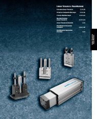
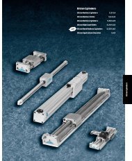
<strong>Position</strong> <strong>Control</strong> <strong>System</strong><strong>Products</strong><strong>Position</strong> Feedback Cylinders 7.3-7.9<strong>Position</strong> Feedback CylinderRodLock 7.10-7.11<strong>Position</strong> Feedback CylinderAccessories 7.12-7.15<strong>Position</strong> Feedback Pneu-Turn 7.16-7.24<strong>Position</strong> <strong>Control</strong> <strong>System</strong> 7.25-7.36Digital Panel Meter 7.37-7.42Electronic <strong>Control</strong>ler 7.43-7.45PFC/PCS Application Checklist 7.46-7.48<strong>Position</strong> <strong>Control</strong>
Bimba <strong>Position</strong> Feedback CylindersThe Bimba <strong>Position</strong> Feedback Cylinder provides continuousposition sensing in alightweight, small-bore air cylinder.Ideal for applications where magnetic position sensing is impractical, where variations in cylinderspeed or stroke are needed, or where an operation requires constant monitoring of cylinder position.Hard chrome-platedcarbon steel piston rodwith blackened threadsand wrench flatsSintered bronzerod bushingAdvantages• Highly accurate: infinite resolution,linearity of ±1percent of full stroke,±0.001” mechanical repeatability.• Less than 0.75” longer than conventionalmagnetic piston cylinders.• Reduces weight and size.• Repairable.• Internally-lubricated seals.Internallylubricated piston sealand rod wiper304 stainless steelcylinder body• Standard wipers and piston bearingstrips for long cylinder life.• Optional bumpers.• Choice of standard 6"lead wire or3-pin connector.• Electronic controllers available fordual set point and scalable analogoutput applications.• Rear head cap can be rotated foroptimal positioning of lead orconnector.Anodized aluminumalloy end caps<strong>Position</strong> <strong>Control</strong>Standard 6"lead oroptional 3-pin connector7.2
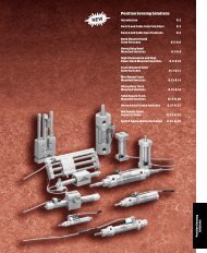
Bimba<strong>Position</strong> Feedback CylindersThis section contains Bimba’s <strong>Position</strong> Feedback <strong>Products</strong>. These products are ideal forapplications that require increased flexibility and adaptability. They are perfect forautomated assembly processes that require quick changeovers or for mass customizedproduct assembly.The <strong>Position</strong> Feedback Cylinder (Model PFC) is alinear pneumatic actuator that containsan internal LRT (Linear Resistive Transducer). The PFC can be used for measuring andgauging, positioning, and "on-the-fly" applications. Combine the PFC with the BimbaPneumatic <strong>Control</strong> <strong>System</strong> Model PCS, Digital Panel Meter Model DPM, or the Electronic<strong>Control</strong>ler described below to maximize performance.The PneuTurn rotary actuator with position feedback (Model PTF) is arotary rack andpinion actuator that has arotary potentiometric feedback transducer attached to theoutput shaft. The PTF can be combined with Bimba’s Pneumatic <strong>Control</strong> <strong>System</strong> ModelPCS described below for closed loop rotary positioning.The Pneumatic <strong>Control</strong> <strong>System</strong> (PCS) is aclosed loop pneumatic motion control systemthat controls the position of the PFC rod orthe PTF shaft. The system includes thecontrol electronics and valves necessary to accurately control any Bimba positionfeedback actuator.The Digital Panel Meter (Model DPM) is adigital panel meter that has a16bit A/Dconverter and built in microprocessor. When combined with the PFC, the repeatability is0.001 inch per inch of stroke. The DPM is great for accurate measuring and gaugingapplications. It is easily calibrated to indicate actual displacement and includes multipleprogrammable set point outputs. Recommended applications include Go/No Go inprocessquality control verification, part identification, and dimensional verification.The Electronic <strong>Control</strong>lers can be used for applications that require accuracy larger than+\- 0.030". It has 10 VDC transducer excitation and fast responding scalable analogoutput capability. Itisgood for applications that use controllers that do not have therequired PFC input impedance of 1Mohm.<strong>Position</strong> FeedbackCylinders<strong>Position</strong> FeedbackCylinder Rod Lock<strong>Position</strong> FeedbackCylinder Accessories<strong>Position</strong> FeedbackPneu-Turn<strong>Position</strong><strong>Control</strong> <strong>System</strong> Digital Panel Meter Electronic <strong>Control</strong>lerPFC/PCSApplication Checklist7.3 ForTechnical Assistance: 800-442-4622
Bimba<strong>Position</strong> Feedback CylindersApplications<strong>Position</strong>ingDispensingDivertingInspectionMeasuringMAXMINTOTWebGuideVerificationProcess AcceptanceStacker7.4
Bimba<strong>Position</strong> Feedback CylindersHowitWorks<strong>Position</strong> FeedbackCylinders<strong>Position</strong> FeedbackCylinder Rod Lock<strong>Position</strong> FeedbackCylinder AccessoriesThe Bimba <strong>Position</strong> Feedback Cylindercontains aLinear Resistive Transducer (LRT) orpotentiometer mounted in the cylinder rearhead. The LRT probe, which has aresistiveelement on one side and acollector strip on theother, isinside the cylinder rod. Awiperassembly is installed in the piston. As the pistonmoves, an electrical circuit is created betweenthe resistive element and collector strip. Avariable resistance (approximately 1KΩ per inchof stroke) proportional to piston position in thecylinder is produced by the cylinder. Consultwww.bimba.com/techctr/techcenter.htm for atable of nominal resistance values at full extendand full retract for various strokes and options.The cylinder can be easily setup to produce ananalog signal compatible with 0-10 VDC PLCanalog inputs.The accuracy of an LRT isdetermined by threefactors: resolution, linearity and repeatability.Resolution refers to the smallest change thatcan be detected on the LRT. The Bimba LRThas infinite resolution, and can be divided intoas many parts as the electronics allow. Forexample, with a12-bit, 4096-part controller,the stroke could be divided into 4096 parts.When 10 VDC are placed on a10" cylinder, thesmallest detectable increment would be 10VDC ÷4096 =2.4 millivolts or 0.0024". Resolutionis stroke sensitive, i.e., the longer thestroke, the less resolution.Linearity refers to the maximum deviation ofthe output voltage to astraight line. The BimbaLRT's linearity is ±1percent of stroke.Repeatability is the ability of the LRT toprovide the same output voltage relative to aunique cylinder position each time the cylinderis cycled. Mechanical repeatability of theBimba <strong>Position</strong> Feedback Cylinder is ±0.001".<strong>Position</strong> FeedbackPneu-Turn<strong>Position</strong><strong>Control</strong> <strong>System</strong> Digital Panel Meter Electronic <strong>Control</strong>lerPFC/PCSApplication Checklist7.5 ForTechnical Assistance: 800-442-4622
Bimba<strong>Position</strong> Feedback CylindersHowtoOrderThe model number of all <strong>Position</strong> Feedback Cylindersconsists of three alphanumeric clusters. These designateproduct type, bore size and stroke length, andmounting style and options. Please refer to the chartsbelow for an example of model number PFC-0912-BFP. This is an 1-1/16" bore, 12" stroke <strong>Position</strong>Feedback Cylinder with block front mounting and aplug connector.PFC-0912-BFPBORE SIZE09 - 1-1/16"17 - 1-1/2"31 - 2"50 - 2-1/2"70 - 3"STANDARD STROKE LENGTHS1 = 1"1.25 = 1.25"Standard Strokes:1", 2", 4", 6", 8", 12", 18" and 24"MOUNTINGBlank - Front noseBF - Block frontX - Universal mountOPTIONSB - BumpersEE - 0.375 -3/8"extra rodextension, etc.L - Low friction 1P - Plug connector1 Low friction optionincludes special sealsand lubrication. RodWiper is omitted.Approximate Power Factors1-1/16" = 0.91-1/2" = 1.72" = 3.12-1/2" = 5.03" = 7.0For example, aPFC-0912-BFP will exertaforce of 0.9 times the air line pressure;aPFC-506-XB will exert aforce of 5.0times the air line pressure, etc.7.6
Bimba<strong>Position</strong> Feedback CylindersBoreBaseStrokeAdder(per inch)MountingBFBlock FrontList PricesXUniversalBBumpersOptionsL*LowFrictionP**PlugConnectors1-1/16" (09) $269.30 $14.70 $17.00 $4.70 $4.20 $2.70 $12.50 $39.201-1/2" (17) 282.10 17.60 18.30 5.50 5.10 6.70 12.50 39.202" (31) 304.90 20.40 22.20 6.90 6.60 8.90 12.50 39.202-1/2" (50) 327.70 23.30 26.80 8.70 8.30 11.50 12.50 39.203" (70) 351.90 26.30 34.40 11.50 12.50 11.50 12.50 39.20*Specify Option Lfor motion <strong>Control</strong> Applications with the PCS <strong>Control</strong> <strong>System</strong>.AccessoriesEEExtraExtension(per inch)Bore Mounting Nut Mounting Bracket Rod Clevis Pivot Bracket1-1/16" (09) D-2545 D-8316 D-8310-A D-8322-A1-1/2" (17) D-8484 D-8318 D-8311-A D-8324-A2" (31) D-508 D-8319 D-8313-A D-8325-A2-1/2" (50) D-2540 D-8320 D-8314-A D-8326-A3" (70) D-5379 D-19127 D-8314-A D-8326-ASee Original Line section for Accessory Prices.<strong>Position</strong> FeedbackCylinders<strong>Position</strong> FeedbackCylinder Rod Lock<strong>Position</strong> FeedbackCylinder Accessories<strong>Position</strong> FeedbackPneu-TurnModel<strong>Control</strong> UnitsPrice120AC4-20MA $243.15120AC0-10DC 243.1512/24DC4-20MA 277.8512/24DC0-10DC 277.85DPM 474.70DPMA 573.05DPMS 555.70DPM-485 81.10DPM-232 81.10DPM-DNET 196.85DPM-A 127.40DPM-R 81.10**Cables (required for plug connector -Poption)Model Description PriceC4-S Straight Female Shielded Cordset IP67, 2m $26.70C4X-S Straight Female Shielded Cordset IP67, 5m 41.40C5 Right Angle Female Shielded Cordset IP67, 2m 26.70C5X Right Angle Female Shielded Cordset IP67, 5m 41.40<strong>Position</strong><strong>Control</strong> <strong>System</strong> Digital Panel Meter Electronic <strong>Control</strong>lerPFC/PCSApplication ChecklistAll prices are F.O.B. Monee, Illinois and are subject to change without notice.7.7 ForTechnical Assistance: 800-442-4622
Bimba<strong>Position</strong> Feedback CylindersNose MountCGEFHA+STROKEPONDBIJKLMM6" LEADS FROMLRT PROBERUniversal Mount (for stud or pivot). Includes bushing.CGEFHU+STROKET+STROKEA+STROKEPONHSDQBIJKLML M K6" LEADS FROMLRT PROBEVRBlock MountA+STROKECYGBBAAZ4HOLES FOR CC S.H.C.S.DD DIA. C’BORE xEEDP.PONXDBXIJ M W MR6" LEADS FROMLRT PROBENote: Mounting holes farthest from rod end are omitted for -L option for 11⁄16" bore.7.8
Bimba<strong>Position</strong> Feedback Cylinders1-1/16" Bore(09)1-1/2" Bore(17)2" Bore(31)2-1/2" Bore(50)3" Bore(70)A 4.59 4.88 5.72 6.41 6.78B Ø0.38 Ø0.50 Ø0.63 Ø0.75 Ø0.75C 0.63 0.88 1.00 1.25 1.25D Ø1.31 Ø1.58 Ø2.09 Ø2.58 Ø3.13E1.75Option L1.521.72 2.10 2.28 2.53F 1.06 1.13 1.38 1.50 1.69G 0.31 0.31 0.38 0.44 0.44H 0.08 0.09 0.11 0.13 0.13I 3/8-24 UNF 7/16-20 UNF 1/2-20 UNF 5/8-18 UNF 5/8-18 UNFJ 0.31 0.44 0.50 0.63 0.63K 7/8-14 UNF 1-1/8-12 UNF 1-1/4-12 UNF 1-3/8-12 UNF 1-1/2-12 UNFL Ø0.87 Ø1.12 Ø1.25 Ø1.37 Ø1.62M 1/8 NPT 1/4 NPT 1/4 NPT 3/8 NPT 3/8 NPTN 0.36 0.36 0.42 0.48 0.55O 0.44 0.44 0.50 0.56 0.63P 0.84 0.81 0.88 1.12 1.88Q 0.62 0.74 0.86 0.99 0.99R Ø1.09 Ø1.36 Ø1.67 Ø2.06 Ø2.44S 0.47 0.56 0.66 0.75 0.81T 5.06 5.44 6.38 7.16 7.60U 5.44 5.91 6.88 7.78 8.22V Ø0.31 Ø0.38 Ø0.44 Ø0.50 Ø0.50W 0.88 1.25 1.44 1.88 2.25X 1.38 1.75 2.25 2.75 3.25Y 0.75 0.69 0.75 0.88 0.94Z 0.88 0.75 1.00 1.25 1.38AA 1.63 Option L1.521.68 1.75 2.13 2.31BB 2.03 2.00 2.41 2.72 2.91CC #10 1/4 3/8 7/16 1/2DD Ø0.33 Ø0.41 Ø0.58 Ø0.67 Ø0.77EE 0.20 0.25 0.39 0.45 0.52Bumper Length Adder: 0.25”Dimensions (in.)<strong>Position</strong> FeedbackCylinders<strong>Position</strong> FeedbackCylinder Rod Lock<strong>Position</strong> FeedbackCylinder Accessories<strong>Position</strong> FeedbackPneu-Turn<strong>Position</strong><strong>Control</strong> <strong>System</strong> Digital Panel Meter Electronic <strong>Control</strong>lerPFC/PCSApplication Checklist7.9 ForTechnical Assistance: 800-442-4622
Bimba<strong>Position</strong> Feedback Cylinder Rod LockHowtoOrderThe model number for all <strong>Position</strong> Feedback Cylinder RodLock actuators consists of three alphanumeric clusters.These designate product type, bore size and strokelength, and mounting style and options.Please refer to the charts below for an example of modelnumber PFCL-0912-XP.This is a1-1/16" bore by 12 inchstroke with an Optional Plug Connector and Low Frictionseals.Bore Size09 - 1-1/16"17 - 1-1/2"31 - 2"50 - 2-1/2"70 - 3"Description<strong>Position</strong> Feedback Cylinderwith Integral Rod LockStandard Stroke Lengths1=1"1.25 =1.25"Standard Strokes:1", 2", 4", 6", 8", 12", 18" and 24"PFCL -0912-XPBEEPOptions- Bumper- Extra Extention- Plug ConnectorMounting StyleBlank - Block FrontX - Universal MountNotes: Low Friction seals on the piston are standard on the PFCL.Rod Wiper is included on PFCL to keep out any contaminates.Only available in Block Front Mounting on the Rod Guide.ListPricesBore1-1/16" (09)1-1/2" (17)2" (31)2-1/2" (50)3" (70)Base$347.80374.40420.80500.60570.70Stroke Adder(per inch)$14.7017.6020.4023.3026.30MountingXUniversal$4.705.506.908.7011.50Refer to page 7.7 for accessory,control units, and cable pricing.BBumpers$4.205.106.608.3012.50OptionsEEExtra Extension(per inch)$2.706.708.9011.5011.50PPlug Connector$39.2039.2039.2039.2039.20Dimensions*Bore W Y Z AA BB FF GG HH JJ KK LL MM OAL Increase Adder1-1/16" (09) 1.06 .62 1.95 2.66 2.91 2.62 .16 #10-32 2.78 1.38 .90 1/8 NPT 1.081-1/2" (17) 1.25 .64 2.75 3.36 3.68 3.13 .25 1/8 NPT 3.38 1.75 1.14 1/4 NPT 1.682" (31) 1.62 .82 3.13 3.97 4.34 4.20 .38 1/8 NPT 4.45 2 .25 1.26 1/4 NPT 1.942-1/2" (50) 1.88 .87 3.62 4.62 5.05 5.34 .33 1/4 NPT 3.67 2.75 1.31 3/8 NPT 2.333" (70) 2.25 .90 4.17 5.17 5.59 5.86 .50 1/4 NPT 6.28 3.25 1.35 3/8 NPT 2.69*All other dimensions are same as standard PFC.All prices are F.O.B. Monee, Illinois and are subject to change without notice.7.10
Bimba <strong>Position</strong> Feedback Cylinder Rod LockHowitWorksIt • Dowel pins ride in the cam groove.• When air pressure is present, piston actuates and dowel pins follow cam toopenposition, allowing piston rod to travel freely through clamp.• In absense of pressure, the spring actuates piston and dowels follow toclosed position, activating the rod clamp.PORT: 50 PSI MIN ACTIVATESPISTON TO RELEASECLAMPCAMROD LOCK PISTONPISTON CAPPISTON SEALSPRINGPISTONUNCLAMPEDCLAMPED<strong>Position</strong> FeedbackCylinders<strong>Position</strong> FeedbackCylinder Rod LockROD GUIDEDOWEL PINROD CLAMPFLATWASHERBUTTONHEAD CAP SCREWSEAL RETAINERDOWEL PINSCAM<strong>Position</strong> FeedbackCylinder AccessoriesROD WIPERROD BUSHING*PFC specifications are on page 7.15.Rod Lock Holding ForcesBoreHolding Force(Pounds)3/4" (04) 401-1/16" (09) 901-1/2 " (17) 1702" (31) 3102-1/2" (50) 5003" (70) 700RODSEALEngineering Specifications*Operating Medium:Operating Pressure:Temperature Range:Lubrication:Cylinder B ody:Rod Guide:Cap:Piston and Rod Seal:Rod and Pivot Bushing:Piston Rod:Expected Service Life:Air50psi minimum (to actuate lock piston)125psi maximum-20 to +200 degrees FHT-99304 stainless steelAluminumAnodized aluminumBuna-NSintered bronzeHard chrome plated carbon steel5million cylinder actuations1million lock actuationsROD CLAMPOperatingGuidelines/Product Precautions• The Rod Lock is not asafety device.• Do not use for intermediatestopping; the cylinder is designedto prevent drift from astationary position.• Load weight must not exceed the stated holding force for thecylinder.• Do not release rod lock if full pressure is present on eitherextend or retract. Uncontrolledmotion will result that coulddamage internal components or cause personal harm.<strong>Position</strong> FeedbackPneu-Turn<strong>Position</strong><strong>Control</strong> <strong>System</strong> Digital Panel Meter Electronic <strong>Control</strong>lerPFC/PCSApplication Checklist7.11 ForTechnical Assistance: 800-442-4622
Bimba<strong>Position</strong> Feedback Cylinder AccessoriesOptions3-pin ConnectorWire ColorsWIRES 6" LEADS PLUGInput Red BlueGround Black BlackOutput White BrownDimensions (in.)BoreN09 0.2517 0.2531 0.3150700.380.44Straight-Models C4-S (2m), C4X-S (5m).Right Angle-Models C5 (2m), C5X (5m)Cable: 24 AWG PVC insulated, fine stranded copper conductors, with Gray PVC jacket7.12
Bimba<strong>Position</strong> Feedback Cylinder AccessoriesMounting NutsABAccessories (in.)AB<strong>Position</strong> FeedbackCylindersCModel D-2540DEBore Model A B C D E1-1/16" (09) D-2545 1.31 0.48 7/8-14 UNF-2B N/A N/A1-1/2" (17) D-8484 1.69 0.61 1-1/8-12 UNF-2B N/A N/A2" (31) D-508 1.88 0.50 1-1/4-12 UNF-2B 1.81 0.032-1/2" (50) D-2540 1.88 0.50 1-3/8-12 UNF-2B 1.81 0.033" (70) D-5379 2.25 0.50 1-1/2-12 UNF-2B 2.25 0.02CModels D-2545D-8484D-508D-5379<strong>Position</strong> FeedbackCylinder Rod Lock<strong>Position</strong> FeedbackCylinder Accessories<strong>Position</strong> FeedbackPneu-TurnMounting BracketEDHIBGCFFKAJBore Model A B C D E F G H I J1-1/16" (09) D-8316 1.75 2.12 1.16 0.875 0.28 0.78 0.66 1.00 0.16 0.321-1/2" (17) D-8318 2.19 2.75 1.44 1.125 0.34 1.06 0.81 1.25 0.19 0.382" (31) D-8319 2.44 3.00 1.59 1.25 0.34 1.19 0.91 1.38 0.22 0.442-1/2" (50) D-8320 2.81 3.75 1.88 1.312 0.41 1.50 1.06 1.62 0.25 0.503" (70) D-19127 3.14 4.38 1.62 1.625 0.34 1.75 1.00 1.89 0.25 0.89<strong>Position</strong><strong>Control</strong> <strong>System</strong> Digital Panel Meter Electronic <strong>Control</strong>lerPFC/PCSApplication Checklist7.13 ForTechnical Assistance: 800-442-4622
Bimba<strong>Position</strong> Feedback Cylinder AccessoriesAccessories (in.)Rod ClevisIAHBJGCFEDKBore Model A B C D E F G H I J K1-1/16" (09) D-8310-A 0.62 1.69 0.88 0.312 0.31 0.62 0.94 1.38 3/8-24 THD 0.22 3/8-24 HEX NUT1-1/2" (17) D-8311-A 0.75 2.00 1.03 0.375 0.38 0.75 1.12 1.62 7/16-20 THD 0.25 7/16-20 HEX NUT2" (31) D-8313-A 0.88 2.31 1.14 0.438 0.44 0.88 1.31 1.88 1/2-20 THD 0.31 1/2-20 HEX NUT2-1/2" (50)&3"(70)D-8314-A 1.00 2.75 1.38 0.50 0.50 1.00 1.50 2.25 5/8-18 THD 0.38 5/8-18 HEX NUTPivot BracketBore Model A B C D E F G H I J K L M1-1/16" (09) D-8322-A 1.31 2.38 1.31 0.312 0.31 1.00 0.25 0.81 0.62 0.16 0.31 1.75 0.281-1/2" (17) D-8324-A 1.62 3.00 1.62 0.375 0.38 1.25 0.31 1.00 0.75 0.19 0.44 2.13 0.342" (31) D-8325-A 1.81 3.25 1.81 0.438 0.44 1.38 0.31 1.19 0.88 0.25 0.44 2.38 0.342-1/2" (50)&3"(70)D-8326-A 2.12 4.00 2.12 0.50 0.50 1.62 0.38 1.38 1.00 0.25 0.62 2.75 0.417.14
Bimba<strong>Position</strong> Feedback Cylinder AccessoriesRepair PartsRepeatability: ±0.001"Cylinder Only.Refer to specifications in the following sections for positioning ormeasuring repeatability. Power supply ripple and A/D error may reducerepeatability when PFC is utilized with industrial control systems.Nonlinearity: ±1percent of full strokeResolution: InfiniteSignal Input: 1 0VDC typicalInput Impedance Required: 1 MOhmSignal Output: > 0to slightly less than FS signal input(The internal electrical stroke is slightly larger than themechanical stroke of cylinder)Maximum speed: 25 in./sec.Rated Life of LRT Wiper: 1,000 1 miles of travelRated Life of Probe: 10 million cycles 1Air Requirements: Filtered to 5micron with 0degree dewpoint recommended.Moisture inside cylinder will cause output signal fluctuation.Pressure Rating: 150 psiTemperature Rating: 0° to200°F 2Interface: 6" standard leads or optional 8mm DIN connectorCylinder Body: 304 stainless steelPiston Rod: Hard chrome plated carbon steel with blackenedthreads and wrench flatsRod Bushing: Sintered bronzeEnd Caps: Anodized Aluminum alloyPiston Seal: Internally lubricated urethane (standard)Internally lubricated Buna (L option)Rod Wiper: Internally lubricated Buna N(omitted on Loption)Rod Seal: Internally lubricated Buna N(N/A on standard model)1Higher velocities increase wear rate.2Special low temperature lubrication is required for positioning applications using option Lseals below 35°F.PARTRPFC-Bore Stroke-Options*RD-53129-Stroke-Options**Engineering SpecificationsESTIMATED CYLINDER WEIGHTS (LBS)1-1/16" 1-1/2" 2 2-1/2" 3PFC- 0.44 0.88 2.02 2.78 3.62PFC-X 0.49 0.96 2.14 2.96 3.85PFC-BF 0.54 1.07 2.28 3.02 4.08ADDER WT/IN 0.06 0.10 0.15 0.20 0.29DESCRIPTIONReplacement CylinderReplacement Probe* Only options required are BF, B,and LasRear Cap is not included.** Only option required for replacement probe is Option P.How to OrderAdd the bore size, stroke and options needed to the basicmodel number shown above for areplacement cylinder.Add the stroke length to the basic model number shownabove for areplacement probe. For example, areplacementprobe for a6"stroke <strong>Position</strong> Feedback Cylinder would beordered as aRD-53129-6.LRT CIRCUIT DIAGRAMSTROKE =0;OUTPUT VOLTAGE =0VOLTSSTROKE =FULL; OUTPUT VOLTAGE =10VOLOUTPUT(WHITE)GROUND(BLACK)+10(RED)<strong>Position</strong> FeedbackCylinders<strong>Position</strong> FeedbackCylinder Rod Lock<strong>Position</strong> FeedbackCylinder Accessories<strong>Position</strong> FeedbackPneu-Turn<strong>Position</strong><strong>Control</strong> <strong>System</strong> Digital Panel Meter Electronic <strong>Control</strong>lerPFC/PCSApplication Checklist7.15 ForTechnical Assistance: 800-442-4622
Bimba<strong>Position</strong> Feedback Pneu-TurnHowitWorksPneu-Turn ® <strong>Position</strong> Feedback Rotary Actuator -Model PTFThe Bimba Pneu-Turn ® position feedback rotary actuator (PTF )providescontinuous shaft position sensing. Standard features include shaft ballbearings and the elimination of mid-rotational backlash. Use the BimbaPTF in conjunction with Bimba’s Pneumatic <strong>Control</strong> <strong>System</strong> (PCS )toachieve rotary shaft positioning accuracy within ±0.5°.POTENTIOMETERANTI-BACKLASHPOTENTIOMETER COUPLER8MM DINCONNECTORANTI-BACKLASH RACKPRECISION BALL BEARINGS7.16
Bimba<strong>Position</strong> Feedback Pneu-TurnThe model number of the Pneu-Turn rotary actuatorwith shaft position feedback capabilities consist ofthree alphanumeric clusters. These designateproduct type, series, angle of rotation, and specialoptions. Please refer to the charts below for anHowtoOrderexample of model number PTF-098180-A1H1. Thisis a1-1/2" bore, single rack, 180° angle of rotationactuator with angle adjustment on both sides andthe plug connector located on the clockwise side.PTF-098 180 - A1H1<strong>Position</strong> FeedbackCylinders<strong>Position</strong> FeedbackCylinder Rod LockSERIES -TORQUE FACTOR098 -1-1/2" Bore, Single Rack196 -1-1/2" Bore, Double Rack247 -2"Bore, Single Rack494 -2"Bore, Double RackPTF base units include ballbearing and anti-backlashoptions.To determine theoretical outputtorque (in-lbs.), place adecimalpoint between the first andsecond digits of the seriesnumber. Then multiply thatnumber by the air line pressurefor the approximate torqueproduced.For example, aPT-098 willproduce an output torque of .98times the air line pressure.STANDARD ANGLEOF ROTATION045 - 45°090 - 90°180 - 180°325 - 325°Larger rotational anglesare available. Contact yourBimba distributor.OPTIONSA1 - Angle adjustment, both sidesA2 - Angle adjustment, counterclockwise rotationA3 - Angle adjustment, clockwise rotationB1 - Bumpers, both sidesB2 - Bumpers, counterclockwise rotationB3 - Bumpers, clockwise rotationC1 - Cushion, both sides 1C2 - Cushion, counterclockwise rotation 1C3 - Cushion, clockwise rotation 1G - Magnalube ® GlubricationH1 - Plug connector, clockwise sideH2 - Plug connector, back of plateH3 - Plug connector, bottom of plateK - Square keyM - MRS ® magnetic position sensingS - Seals, oil service 2V - High temperature option (0°F to 250°F) 31 Cushions will reduce positioning accuracy.2 Oil service not recommended for applications atpressures less than 40 psi.3 Ball bearing units with high temperature option is0°F to 250°F.®Magnalube is aregistered trademark of CarletonStuart Corporation.<strong>Position</strong> FeedbackCylinder Accessories<strong>Position</strong> FeedbackPneu-Turn<strong>Position</strong><strong>Control</strong> <strong>System</strong> Digital Panel Meter Electronic <strong>Control</strong>lerPFC/PCSApplication Checklist7.17 ForTechnical Assistance: 800-442-4622
Bimba<strong>Position</strong> Feedback Pneu-TurnOption Combination AvailabilityDue to design or compatibility restrictions, the following options maynot be ordered in combination. For example, C(Cushions) and B(Bumpers) are not available in combination.O p t i o nS e r i e s1- 1 / 2 " ( 0 9 8 ) N/A1- 1 / 2 " ( 1 9 6 ) N/A2"( 2 4 7 ) N/A2"( 4 9 4 ) N/AA B C K M S VC,SC,SC,SC,SB,SB,SB,SB,SN/A V B,CN/A V B,CN/A V B,CN/A V B,CNote: Temperature range of ball bearing units with high temperature option is 0ºFto +250ºF.MMMMB o r e S i z e a n d T y p eS i n g l e( 0 9 8 )ListPrices1 - 1 / 2 "2 "D o u b l e S i n g l e( 1 9 6 )( 2 4 7 )D o u b l e( 4 9 4 )B a s e P r ic e$546.70 $686.30 $648.00 $849.10A d d e r p e r 4 5 ° R o t a t io n8.30 16.50 13.90 27.70A n g le A d ju s t m e n t( A 1 , A 2 , A 3 )$11.90 per end $14.70 per endB u m p e r ( B 1 , B 2 , B 3 )5.20 per end 5.90 per endC u s h io n ( C 1 , C 2 , C 3 )12.10 per end 15.10 per endS q u a r e K e y ( K )2.10 3.10M R S ( M )13.90 25.50O il S e r v ic e S e a ls ( S )18.70 21.40H ig h T e m p e r a t u r e O p t io n( V ) S in g le R a c kH ig h T e m p e r a t u r e O p t io n( V ) D o u b le R a c k12.50 13.9024.90 27.70A V C o m b in a t io n 1.20 per end plus Aand Vadders 1.50 per end plus Aand VaddersB V C o m b in a t io n .80 per end pllus Band Vadders 1.20 per end plus Band VaddersC V C o m b in a t io n 1.40 per end plus Cand Vadders 1.70 per end plus Cand VaddersS V C o m b in a t io n 19.90 per end plus Sand Vadders 22.70 per end plus Sand VaddersNo charge options -G,H1, H2, H3.CablesModel Description PriceC4-S Straight Female Shielded Cordset IP67, 2m $26.70C4X-S Straight Female Shielded Cordset IP67, 5m 41.40C5 Right Angle Female Shielded Cordset IP67, 2m 26.70C5X Right Angle Female Shielded Cordset IP67, 5m 41.40All prices are F.O.B. Monee, Illinois and are subject to change without notice.7.18
Bimba<strong>Position</strong> Feedback Pneu-TurnELM8 CONNECTORY1.322X UxVDOPlug connector shown in standard position.The H1 option dimensionally positions theconnector on the clockwise rotation side.MXSingle Rack Models (in.)NTWQSAXIALLOADL12X DR THRU FORFSCH CAP SCRCABL2SIDE 1 SIDE 2"A"RWDF KEYSHOWN @CENTEROF ROTATIONØH"B"+.000-.0012X JBODYSHAFT+.000ØG -.001 ID PILOT xPD2X KPORT<strong>Position</strong> FeedbackCylinders<strong>Position</strong> FeedbackCylinder Rod Lock<strong>Position</strong> FeedbackCylinder AccessoriesZ Y Z<strong>Position</strong> FeedbackPneu-TurnBACKB o r e A B C E FLG ( B a l l B e a r i n gI . D .P i l o t)H J K L M1 - 1 / 2 " ( 0 9 8 ) 2 . 3 8 1 . 8 1 0 . 9 0 2 . 8 4 5 / 1 6 " S . H . C . S . 1 . 3 7 5 0 . 6 2 5 1 . 5 6 1 / 8 N P T 1 . 4 4 9 2 . 2 52 " ( 2 4 7 ) 3 . 0 0 2 . 3 8 1 . 1 9 3 . 7 5 5 / 1 6 " S . H . C . S . 1 . 8 7 5 0 . 8 7 5 2 . 0 8 1 / 4 N P T 1 . 9 1 8 2 . 5 6B o r e N O P Q R S T U V W X Y Z1 - 1 / 2 " ( 0 9 8 ) 1 . 3 8 1 . 1 2 0 . 0 9 0 . 6 2 # 4 0 5 2 . 0 9 1 . 1 5 5 / 1 6 - 1 8 0 . 6 2 0 . 3 1 1 . 6 2 0 . 4 5 1 . 1 92 " ( 2 4 7 ) 2 . 0 0 1 . 2 8 0 . 1 0 0 . 7 5 # 6 0 6 2 . 5 6 1 . 2 8 5 / 1 6 - 1 8 0 . 6 2 0 . 2 8 2 . 0 0 0 . 4 5 1 . 5 0<strong>Position</strong><strong>Control</strong> <strong>System</strong> Digital Panel Meter Electronic <strong>Control</strong>lerPFC/PCSApplication Checklist7.19 ForTechnical Assistance: 800-442-4622
Bimba<strong>Position</strong> Feedback Pneu-TurnDouble Rack Models (in.)Plug connector shown in standard position.The H1 option dimensionally positions theconnector on the clockwise rotation side.H2 OptionH3 OptionB o r e A B C D E FG ( B a l l B e a r i n gI . D . P i l o t )H J K L M1- 1 / 2 " ( 1 9 6 ) 2. 3 8 1. 8 1 0. 9 0 1. 8 8 4 . 1 92"( 4 9 4 ) 3. 0 0 2. 3 8 1. 1 9 2. 5 6 5 . 1 35 / 1 6 "S . H . C . S .5 / 1 6 "S . H . C . S .1. 3 7 5 0. 6 2 5 1. 5 6 1/ 8 N P T 1. 4 4 9 2 . 2 51. 8 7 5 0. 8 7 5 2. 0 8 1/ 4 N P T 1. 9 1 8 2 . 5 6B o r e N O P Q R S T U V W X Y Z1 - 1 / 2 " ( 1 9 6 ) 1 . 3 8 1 . 1 2 0 . 0 9 0 . 6 2 # 4 0 5 2 . 0 9 1 . 1 5 5 / 1 6 - 1 8 0 . 6 2 0 . 3 1 1 . 6 2 0 . 4 5 1 . 1 92 " ( 4 9 4 ) 2 . 0 0 1 . 2 8 0 . 1 0 0 . 7 5 # 6 0 6 2 . 5 6 1 . 2 8 5 / 1 6 - 1 8 0 . 6 2 0 . 2 8 2 . 0 0 0 . 4 5 1 . 5 07.20
Bimba<strong>Position</strong> Feedback Pneu-TurnSingle Rack Options (in.)(Dimensional variations from standard as shown)A d d e r p e r D e g r e e o fR o t a t io n1 - 1 / 2 " ( 0 9 8 ) 2 " ( 2 4 7 )L 1 L 2 L 1 L 20 . 0 0 9 7 0 . 0 0 9 7 0 . 0 1 3 7 0 . 0 1 3 7B a s e U n it ( N o O p t io n s ) 2 . 3 4 2 . 3 4 2 . 8 4 2 . 8 4B u m p e r B o t h S id e s ( B 1 ) 2 . 4 9 2 . 4 9 3 . 0 4 3 . 0 4B u m p e r C C W S id e ( B 2 ) 2 . 3 4 2 . 4 9 2 . 8 4 3 . 0 4B u m p e r C W S id e ( B 3 ) 2 . 4 9 2 . 3 4 3 . 0 4 2 . 8 4C u s h io n B o t h S id e s ( C 1 ) 2 . 9 8 2 . 9 8 3 . 6 5 3 . 6 5C u s h io n C C W S id e ( C 2 ) 2 . 3 4 2 . 9 8 2 . 8 4 3 . 6 5C u s h io n C W S id e ( C 3 ) 2 . 9 8 2 . 3 4 3 . 6 5 2 . 8 4O il S e r v ic e S e a ls ( S ) 2 . 7 7 2 . 7 7 3 . 3 8 3 . 3 8O il S e r v ic e w it h A n g leA d ju s t m e n t ( A S )3 . 4 1 3 . 4 1 4 . 1 9 4 . 1 9<strong>Position</strong> FeedbackCylinders<strong>Position</strong> FeedbackCylinder Rod Lock<strong>Position</strong> FeedbackCylinder AccessoriesDouble Rack Options (in.)(Dimensional variations from standard as shown)<strong>Position</strong> FeedbackPneu-Turn“CCW Side” –refers to the extreme rotation of the shaft in thecounter-clockwise direction as viewed from themounting pilot side of the actuator.The location of the optional feature chosen willbe on tube Bfor single rack models and tube Cfor double rack models.A d d e r p e r D e g r e e o fR o t a t io n1 - 1 / 2 " ( 0 9 8 ) 2 " ( 2 4 7 )L 1 L 2 L 1 L 20 . 0 0 9 7 0 . 0 0 9 7 0 . 0 1 3 7 0 . 0 1 3 7B a s e U n it ( N o O p t io n s ) 2 . 3 4 2 . 3 9 2 . 8 4 2 . 8 9B u m p e r B o t h S id e s ( B 1 ) 2 . 4 9 2 . 3 9 3 . 0 4 2 . 8 9B u m p e r C C W S id e ( B 2 ) 2 . 4 9 2 . 3 9 3 . 0 4 2 . 8 9B u m p e r C W S id e ( B 3 ) 2 . 4 9 2 . 3 9 3 . 0 4 2 . 8 9C u s h io n B o t h S id e s ( C 1 ) 2 . 9 8 2 . 3 9 3 . 6 5 2 . 8 9C u s h io n C C W S id e ( C 2 ) 2 . 9 8 2 . 3 9 3 . 6 5 2 . 8 9C u s h io n C W S id e ( C 3 ) 2 . 9 8 2 . 3 9 3 . 6 5 2 . 8 9O il S e r v ic e S e a ls ( S ) 2 . 7 7 2 . 3 9 3 . 3 8 2 . 8 9O il S e r v ic e w it h A n g leA d ju s t m e n t ( A S )3 . 4 1 2 . 3 9 4 . 1 9 2 . 8 9“CW Side” –refers to the extreme rotation of the shaft in theclockwise direction as viewed from themounting pilot side of the actuator.The location of the optional feature chosen willbe on tube Afor both single and double rackmodels.<strong>Position</strong><strong>Control</strong> <strong>System</strong> Digital Panel Meter Electronic <strong>Control</strong>lerPFC/PCSApplication Checklist7.21 ForTechnical Assistance: 800-442-4622
Bimba<strong>Position</strong> Feedback Pneu-TurnOptionsMRS ® Magnetic <strong>Position</strong> SensingMagnetic pistons are located on the Aand Btubes of both the single and double rack rotary actuators,guaranteeing switch operation at any point in the rotation.L1 +MRS LENGTH ADDITIONAMAGNETICPISTONL2 +MRS LENGTH ADDITIONMAGNETICPISTONBL1 +MRS LENGTH ADDITIONACL1MAGNETICPISTONL2 +MRS LENGTH ADDITIONL2DMAGNETICPISTONBMRS ® Length Adder (in.)D e g r e e s 0 9 8 / 1 9 6 2 4 7 / 4 9 44 5 ° 0 . 7 5 0 . 7 59 0 ° 0 . 5 3 0 . 4 41 8 0 ° 0 . 0 9 0 . 0 03 2 5 ° 0 . 0 0 0 . 0 0SIDE 1 SIDE 2SIDE 1 SIDE 2Woodruff Key (in.)Square Key (in.)K e yN o .W i d t hH e i g h t4 0 5 0 . 1 2 5 0 0 . 0 6 36 0 6 0 . 1 8 7 5 0 . 0 9 4Cushion(C Option) (in.)Option DimensionsB o r eS i ze1 - 1 / 2 "( 0 9 8 / 1 9 6 )2 "( 2 4 7 / 4 9 4 )L e n g t hW i d t hH e i g h tH0 . 7 9 7 0 . 1 8 8 0 . 1 8 8 0 . 0 9 41 . 7 8 1 0 . 2 5 0 0 . 2 5 0 0 . 1 2 5Angle Adjustment with Oil Service Seals(AS Option) (in.)Angle Adjustment with Cushion(AC Option) (in.)Angle Adjustment(A Option) (in.)B o r e A B C D E F G H J1 - 1 / 2 "0 9 8 a n d 1 9 62 "2 4 7 a n d 4 9 41 . 5 6 0 . 7 7 0 . 2 7 0 . 3 3 0 . 4 2 0 . 3 4 1 / 8 N P T 0 . 6 7 0 . 6 72 . 0 8 0 . 8 7 0 . 3 1 0 . 4 9 0 . 5 3 0 . 4 1 1 / 4 N P T 0 . 9 7 0 . 9 77.22
Bimba<strong>Position</strong> Feedback Pneu-TurnBASingle Rack ModelRepair Parts1BABBall Bearing ® OptionK-P-PTF(Potentiometer Kit)(Includes K-G-PTF Kit)<strong>Position</strong> FeedbackCylindersCCADouble Rack Model813 6 7 14SECTION A-A114611818CD15AB1617 136 710SECTION C-CK-C-PTF(Connector Kit)(Includes K-G-PTF Kit)4320192SECTION B-BK-G-PTF(Gasket Kit)15<strong>Position</strong> FeedbackCylinder Rod Lock<strong>Position</strong> FeedbackCylinder AccessoriesRepair KitsRepair Parts2 2" bore requires 8or16.Q u a n t i t y R e q u i r e dB e a r i n g K i t ( K - A - P T - R )N o . P a r t D e s c r i p t i o nS i n g l e D o u b l eF r o n t S h a f t B a llP T - 3 - R1P T - 1 - R A c t u a t o r B o d y1 1B e a r in gP T F - 2 S h a f t / P in io n A s s e m b ly1 1R e a r S h a f t B a llP T - 4 - RB e a r in gP T - 3 - R F r o n t S h a f t B a ll B e a r in g1 11P T - 4 - R R e a r S h a f t B a ll B e a r in g1 1S h a f t K i t ( K - S - P T F )P T - 5 S h a f t K e y1 1S h a f t / P in io nP T F - 2P T - 7 - X R a c k S u p p o r t1 2A s s e m b ly1P T F - 81P is t o n S e a l2 4P T - 5 S h a f t K e y 1P T - 9P is t o n W e a r R in g( R e q u ir e d f o r O il S e r v ic e o n ly )2 2S e a l K i t ( K - L - P T F )P T - 1 0 M a g n e t2 2PT F - 8 Pis t o n S e a ls2P T - 1 1 B u m p e r2 2C y lin d e r B o d y A s s e m b lyG a s k e t K i t ( K - G - P T F )P T - 1 3 ( I n c lu d e s B o d y , E n d C a p , a n d 2 4Ga s k e t1R e t a in e r R in g )C y lin d e r B o d y R e t a in e r C a pP T - 1 426 1 2C o n n e c t o r K i t ( K - C - P T F )S c r e wP T - 1 5 C y lin d e r B o d y T h r e a d S e a l 2 2Co n n e c t o r A s s y . 1P T - 1 6C y lin d e r B o d y T h r e a d S e a lGa s k e t22 2R in gP T - 1 7 C y lin d e r B o d y J a m N u t2 2P o t e n t i o m e t e r K i t ( K - P - P T F )P T - 1 8 A n g le A d ju s t m e n t S c r e w2 2PinH e a d e r1P T - 1 9 R e t a in in g R in g2 2P o t e n t io m e t e rP T - 2 0 S h im P a c k a g e1 1A s s y .11 Double Rack Models require two repair kits per rotary actuator. OilC o u p le rP o t e n t io m e t e r1Service Option: Single Rack models require four oil service seals or twooil service seal kits. Double Rack models require four oil service seals andtwo standard seals or two oil service seal kits and one standard seal kit.Ga s k e t2<strong>Position</strong> FeedbackPneu-Turn<strong>Position</strong><strong>Control</strong> <strong>System</strong> Digital Panel Meter Electronic <strong>Control</strong>lerPFC/PCSApplication Checklist7.23 ForTechnical Assistance: 800-442-4622
Bimba<strong>Position</strong> Feedback Pneu-TurnEngineering SpecificationsRepeatability: ±0.01° (of potentiometer itself)Nonlinearity: ±.88° (± 0.25% of 340±4°)Resolution: InfiniteSignal Input: 1 0VDC typicalInput Impedance Required: 100 KohmSignal Output: 0to 10 VDC FS (depends onFS mechanical rotation)Rated Life of Potentiometer: 10 million cyclesTemperature Coefficient: ±600 ppm/°CElectrical Rotation: 340° ±4°General SpecificationsRotary action of the Pneu-Turn rotary actuator isachieved through the use of arack and pinionassembly. Just as with any hydraulic or pneumaticcylinder, the speed of rotation may be controlledthrough the use of flow controls. The PTF may alsobe controlled with Bimba’s Pneumatic <strong>Control</strong><strong>System</strong>, Model PCS.Care should be taken to insure that the inertial forcedoes not exceed the published torque capacity.Port <strong>Position</strong>ingPorts on the PTF may be repositioned toaccommodate any air line configuration byloosening the three body retainer screws. Oncedesired port positions are obtained, screws must betightened to specified torque values in the tablebelow.LubricationThe PTF is prelubricated at the factory forextensive, maintenance free operation. The life ofthe rotary actuator can be lengthened by providingadditional lubrication with an air line mist lubricatoror direct introduction of the oil to the actuator every500 hours of operation. Recommended oils forBuna Nseals are medium to heavy inhibitedhydraulic or general purpose oil.The rack and pinion gear and ball bearings areprelubricated at the factory for extensivemaintenance free operation. Ifadditional lubricationis required, use ahigh grade bearing grease.Woodruff Key LocationThe standard position of the woodruff key is 12o’clock at the center of rotation.RatingsPressure Rating: 150 psi air or oil with SOptionRotation Tolerance:1-1/16" -2"bore is-0° to+10°. The AngleAdjustment Option allows 45° of adjustability. Ifcushions are ordered in conjunction with the angleadjustment option, adjustability will be 10°.Temperature Range: Standard Seals: -20° to200°F; VOption High Temp seals: 0° to250°.Note: If used for positioning applications, it isrecommended to use low temperature lubricant fortemperatures less than 35°F.Backlash: Both single and double rack modelshave zero mid-rotational and end of rotationbacklash.Breakaway: Less than 3psi.SeriesTheoretical Torque Capacity(in-lbs/PSI)7.241-1/2" 2"(098) (196) (247) (494)0.982 1.963 2.468 4.935Bearing Load (Axial lbs) 110 110 130 130Bearing Load (Radial lbs) 425 425 740 740Distance between bearingmidpoints (in)Maximum rate of rotation(@ 100 PSI with no load)1.71 1.71 1.82 1.821500 deg/sec 1500 deg/sec 1000 deg/sec 1000 deg/secWeight (approximate oz) 47 88 103 150Body Retainer cap screw recommendedtightening torque (in-lbs)20 20 20 20
Bimba <strong>Position</strong> <strong>Control</strong><strong>System</strong>The Bimba Pneumatic <strong>Control</strong> <strong>System</strong> (ModelPCS) is designed to control any pneumatic Bimbaposition feedback actuator. This includes the<strong>Position</strong> Feedback Cylinder (PFC) for linear motionand the <strong>Position</strong> Feedback Pneu-Turn (PTF) forrotary motion. The system is aclosed-loopelectronic controller with pneumatic valves that canaccurately position the actuator rod orshaft andhold it in position with ahigh degree of accuracyand force. The system accomplishes the long termgoal of using pneumatic technology to accuratelystop and hold the rod orshaft at any desiredposition.The standard PCS accepts a0-10 VDC, 0-20 mAor 4-20 mA analog command signal. Thecommand signal is used as areference to move toand hold aspecific position. For example, if theapplication has astroke of 10 inches (i.e., theelectrical zero and span is set for a10inch stroke),then a1volt change in the command voltage isequal to a1inch movement. Similarly, achange incommand signal of 0.005 ofavolt equals aposition change of 0.005 ofaninch for the same10 inch stroke application. If the application has astroke of 5inches, achange of 1volt in thecommand signal represents a1/2" inch movement.For rotary applications, the convention is similar. Ifthe application has arotation of 180 degrees, thena1volt change in the command signal is equal to18 degrees of rotation.HowItWorksBimba Pneumatic <strong>Control</strong> <strong>System</strong> Model PCSThe system utilizes the feedback from the actuatorto close the control loop. The control loopcompares the system’s command signal (the 0-10VDC, 0-20mA, or 4-20mA input command signal)to the feedback signal from the actuator. Thedifference between the command and feedback isreferred to as the error term. When the error termis zero, all valves close, trapping air on both sidesof the actuator piston. (The error term isconsidered to be zero when it is within thedeadband range. The deadband range is anadjustable range that determines the finalrepeatability of the system. The Application Sizingchart located later in this section showsrecommended deadband ranges for givenapplication parameters.) This holds the rod orshaft at it’s commanded position. If some force orweight attempts to move the rod orshaft out of thecommanded position, the system will react byincreasing the restoring force eventually to fullsupply pressure, if necessary. Likewise, if thecommand signal changes, the system will respondto make the feedback equal the command signal.There are four adjustments on the PCS system,adjustable via four trim pots. They include theZero, Span, Decel, and Deadband adjustments.The Zero and Span adjustments allow you to setthe zero and full scale position of the actuator tomatch the input (command) signal. The Decel andDeadband adjustments are used to optimize theperformance of the system based on applicationparameters. These adjustments are described indetail in the Operating Manual, which is includedwith each system.The actual accuracy/repeatability of themovements will depend on many factors, includingsignal noise, load, velocity, supply pressure, supplyvoltage, and application friction. Refer to theApplication Sizing charts found later in this sectionfor detailed information regarding sizing andsuggestions for your application.<strong>Position</strong> FeedbackCylinders<strong>Position</strong> FeedbackCylinder Rod Lock<strong>Position</strong> FeedbackCylinder Accessories<strong>Position</strong> FeedbackPneu-Turn<strong>Position</strong><strong>Control</strong> <strong>System</strong> Digital Panel Meter Electronic <strong>Control</strong>lerPFC/PCSApplication Checklist7.25 ForTechnical Assistance: 800-442-4622
Bimba <strong>Position</strong> <strong>Control</strong><strong>System</strong>The model number for all Pneumatic <strong>Control</strong><strong>System</strong>s consist of three alpha numeric clusters.These designate product type, flow size, andoptions. Please refer to the charts below for anHowtoOrderPCS-1-Qexample of model number PCS-1-Q. This is asystem with aCvof0.02 and the Quick Connectconnector option.PNEUMATIC CONTROL SYSTEMFLOW TYPE1-Cv =0.022-Cv =0.043-Cv =0.085-Cv =0.107-CV =0.118-CV =0.25OPTIONSBlank - Nocables or connectorsN - No enclosureQ - Quick connect receptacles(cables sold separately)This initial offering covers 1-1/16" (09) through 2"(31) bore size <strong>Position</strong> Feedback Cylinders. Largerflow PCS <strong>System</strong>s are available for the larger boresizes Refer to TRD <strong>Position</strong> <strong>Control</strong> <strong>System</strong>Product Catalog or contact Bimba for furtherdetails. Refer to the <strong>Position</strong> Feedback Cylindersection (page 7.6) and the <strong>Position</strong> FeedbackPneu-Turn section (page 7.17) for orderinginformation regarding either actuator. Ensure thatthe <strong>Position</strong> Feedback Cylinder -L option isspecified for motion control applications.*The Cv values are approximated. The velocities for the different systems are shown in the sizing recommendations table.Note: All PCS units can accept 0-10 VDC, 0-20 mA, or 4-20 mA signals.M o d e lP C S - 1P C S - 2P C S - 3P C S - 5PCS-7PCS-8List PricesB a s e$661.50661.50661.50661.50661.50661.50O p t i o n sN$82.7082.7082.7082.7082.7082.70Q$220.50220.50220.50220.50220.50220.50P a r tN u m b e rPC S - C B L - P W RPC S - C B L - P W R - XPC S - C B L - C M DPC S - C B L - C M D - XPC S - C B L - F B KPC S - C B L - F B K - XAccessoriesD e s c r i p t i o n2 m e t e r P o w e r C a b le f o r Q u ic k C o n n e c t O p t ion5 m e t e r P o w e r C a b le f o r Q u ic k C o n n e c t O p t io n2 m e t e r C o m m a n d S ig n a l C a b le f o r Q u ic k C o n n e c t O p t io n5 m e t e r C o m m a n d S ig n a l C a b le f o r Q u c k C o n n e c t O p t io n2 m e t e r F e e d b a c k C a b le f o r Q u ic k C o n n e c t O p t io n5 m e t e r F e e d b a c k C a b le f o r Q u ic k C o n n e c t O p t io nP r i c e$30.1546.3548.7069.5057.9581.10One power, command and feedback cable required if option Qispurchased.All prices are F.O.B. Monee, Illinois and are subject to change without notice.7.26
Bimba <strong>Position</strong> <strong>Control</strong><strong>System</strong>DimensionsShown in inches (millimeters)Enclosure<strong>Position</strong> FeedbackCylinders.06(1.5)3.06(77.7)1.75(44.5).64(16.3)4.56(115.9)4.28(108.7)3.40(86.4).44(11.2).14(3.5)5x1/8 NPT(G 1/8METRICPORT)1.4336.3<strong>Position</strong> FeedbackCylinder Rod Lock1.25(31.8)1.25(31.8)2.50(63.5)MODEL #6.16(156.5).678xEXHAUSTHOLES(4 EACH SIDE)4xØ5/16 THRU(Ø 8.0 THRU)3xSTRAIN RELIEFCABLE COLLETS7.50(190.5)6.80(172.7).35(8.9)2.45(62.2).65(16.5).65(16.5).65(16.5).65(16.5)<strong>Position</strong> FeedbackCylinder Accessories<strong>Position</strong> FeedbackPneu-Turn.06(1.5)1.25(31.8)1.25(31.8)2.50(63.5)3.06(77.7)1.75(44.5)MODEL #6.16(156.5).67.70(17.8)Option Q(Quick Connect Receptacal)4.56(115.9)4.28(108.7)3.40(86.4).44(11.2).14(3.5)7.50(190.5)6.80(172.7)5x1/8 NPT(G 1/8METRICPORT)1.4336.32.45(62.2).65(16.5).65(16.5).65(16.5).65(16.5)<strong>Position</strong><strong>Control</strong> <strong>System</strong> Digital Panel Meter Electronic <strong>Control</strong>ler8xEXHAUSTHOLES(4 EACH SIDE)4xØ5/16 THRU(Ø 8.0 THRU).35(8.9)POWER, COMMAND &FEEDBACKQUICK CONNECT CABLE ASSEMBLIESPFC/PCSApplication Checklist7.27 ForTechnical Assistance: 800-442-4622
Bimba <strong>Position</strong> <strong>Control</strong><strong>System</strong>PCS-CBL-<strong>PW</strong>RSPECIFICATIONS5CONDUCTORS OF 22 AWG LEADS RATEDTO 250 VAT4AMPSSHIELDED78.74(2 M)1.70(43.2)1.00(25.4)Ø.55(Ø14.0)DimensionsShown in inches (millimeters)432Quick Connect Cables51(M12 x1)PCS-CBL-<strong>PW</strong>R-XSPECIFICATIONS5CONDUCTORS OF 22 AWG LEADS RATEDTO 250 VAT4AMPSSHIELDED196.85(5 M)1.70(43.2)1.00(25.4)Ø.55(Ø14.0)453 12(M12 x1)PCS-CBL-<strong>PW</strong>R Wire Color CodesC o l o rP i nD e s c r i p t i o nB r o w n 1 P o s it iv eW h it e 2 N / CB lu e 3 N e g a t iv eB la c k 4 N / CGreen/Yellow5 N / CPCS-CBL-CMD Wire Color CodesC o l o rP i nD e s c r i p t i o nB r o w n 1 I n p u tW h it e 2 @ P o s it io nB lu e 3 G r o u n dB la c k 4 C u r r e n t P o s it io nG r ey 5 N / CP in k 6 N / CPCS-CBL-CMDSPECIFICATIONS6CONDUCTORS OF 24 AWG LEADS RATEDTO EITHER 30 VAC OR 36 VDC AT 4AMPSSHIELDED78.74(2 M)PCS-CBL-CMD-XSPECIFICATIONS6CONDUCTORS OF 24 AWG LEADS RATEDTO EITHER 30 VAC OR 36 VDC AT 4AMPSSHIELDED196.85(5 M)1.65(41.9)32Ø.56(Ø14.2)451.65(41.9)32Ø.56(Ø14.2)4516(M12 x1)16(M12 x1)PCS-CBL-FBKPCS-CBL-FBK-XSPECIFICATIONS3CONDUCTORS OF 24 AWG LEADS RATEDTO 120 VAT4AMPSSHIELDED1.38(9.6)1.37(34.8)78.74(2 M)1.73(43.9)Ø.55(Ø14.0)41SPECIFICATIONS3CONDUCTORS OF 24 AWG LEADS RATEDTO 120 VAT4AMPSSHIELDED1.38(9.6)1.37(34.8)196.85(5 M)1.73(43.9)Ø.55(Ø14.0)41(M8 x1) 4 33 2(M12 x1)(M8 x1) 4 33 2(M12 x1)7.28
Bimba <strong>Position</strong> <strong>Control</strong><strong>System</strong>DimensionsShown in inches (millimeters)Option N(No Enclosure)PCS –1,2,3<strong>Position</strong> FeedbackCylinders+24VDCGNDTB1PC Board5.60(142.2)3214-15.60(142.2)Snap Track.66(16.8)<strong>Position</strong> FeedbackCylinder Rod LockABCSHIELDPOWERTB2SENSORTB4INPUTCUR POS@POSGNDTB3TP3TP2REDGREENDECELDEADBANDZEROSPAN4.00(101.6)4.15(105.4)<strong>Position</strong> FeedbackCylinder AccessoriesSHIELDSIGNALGROUND.85(21.6)2.57(65.3)1.92(48.8).62(15.7).94(23.9)Valve/Manifold.14(3.6)3.90(99.0)1.67(42.4)1.42(36.0).19(4.8)5x1/8 NPT(G 1/8 METRICPORT).75(19.0).38(9.65).65(16.5).65(16.5).65(16.5).65(16.5).84(21.3)2xØ.21(2 xØ5.3)4.28(108.7)Valve Cable25'(6.35 M)PCS –4,5,6,71.30(33.0).62(15.2).98(24.9)<strong>Position</strong> FeedbackPneu-Turn<strong>Position</strong><strong>Control</strong> <strong>System</strong> Digital Panel Meter Electronic <strong>Control</strong>lerPFC/PCSApplication Checklist7.29 ForTechnical Assistance: 800-442-4622
Bimba <strong>Position</strong> <strong>Control</strong><strong>System</strong>SpecificationsD e s c r i p t i o nZ e r o A d ju s t m e n tS p a n A d ju s t m e n tS p e c i f i c a t i o n5 0 % o f t o t a l f u ll s c a le o u t p u t b e t w e e nb o t h a d ju s t m e n t sDE C E LD e a d b a n dA d ju s t m e n tA d ju s t m e n t@ P o s it io nC u r r e n t P o s it io nOp e r a t io nI n p u ta t P o w e r L o s sS u p p ly V o lt a g eOp e r a t in gA irP r e s s u r eR e q u ir e m e n tA p p r o x im a t e ly 0 . 5 t o 1 3 . 5 v o lt sA p p r o x im a t e ly 0 . 0 0 5 t o 0 . 5 0 0 v o lt sD is c r e t e o u t p u t t h a t s in k s t o g r o u n d w h e n w it h ind e a d b a n d z o n e . 2 0 m A M a x i m u m0 t o 1 0 V D C s ig n a l, 1 M o h m in p u t im p e d e n c e r e q u ir e df o r in p u t d e v ic e . S c a le d w it h z e r o a n d s p a n a d ju s t m e n t sA ll v a lv e s c lo s e a t p o w e r lo s s2 3 . 5 t o 2 4 . 5 V D C , 1 a m p7 0 t o 8 0 p s igR e g u la t e d a n d f ilt e r e d t o 5 m ic r o nO p e r a t io n a l T e m p e r a t u r e R a n g e0 t o 1 0 0 d e g r e e s F ( E le c t r o n ic s \ P C B o a r d )R e v e r s e P o la r it y P r o t e c t e dO v e r v o lt a g e P r o t e c t e dApplication Sizing and “Rules of Thumb”PFC Cylinder/PCS Valve <strong>System</strong> Matching and Sizing Recommendations 1Bore Size PCS ModelStrokeRangeMaximumPayload @AverageVelocity(lbs.)MaximumAverageVelocitywithoutovershoot(in/sec)MaximumExternalFriction(lbs.)Zero FrictionDeadbandWidth perinch of stroke1/2MaximumFrictionDeadbandW idth perinch ofstrokeMaximumFrictionDeadbandW idth perinch ofstrokeMinimumStep (in.)1-1/16" (PFC-09) PCS-1 2" to 7" 1 2.75 0 0.005" N/A N/A 0.081-1/16" (PFC-09) PCS-1 8" to 24" 30 4.00 5 0.004" 0.008" 0.016" 0.2-0.391-1/2" (PFC-17) PCS-1 1" to 3" 2 2.50 0 0.0025" N/A N/A 0.041-1/2" (PFC-17) PCS-2 4" to 24" 50 5.50 10 0.002" 0.004" 0.008"2timesdeadband2" (PFC-31) PCS-2 1" to 2" 4 2.75 0 0.005" N/A N/A2timesdeadband2" (PFC-31) PCS-3 3" to 24" 90 6.50 20 0.0015" 0.003" 0.006"2timesdeadband2times2-1/2" (PFC-50) PCS-5 3" to 24" 120 2.00 35 0.009" 0.006" 0.006" deadband3" (PFC-70) PCS-7 3" to 24" 200 2.00 50 0.004" 0.004" 0.006"2timesdeadband3-1/4"PCS-7 5" to 24" 235 2.00 60 0.004" 0.004" 0.006"2timesdeadband4" PCS-7 3" to 4" 360 2.00 90 0.008" N/A N/A2timesdeadband4" PCS-8 5" to 25" 360 2.00 90 0.004" 0.004" 0.006"2timesdeadband1 If your application requires lower velocities or payloads, you may be able to reduce the minimum recommended deadbandsetting, or if your deadband requirements can accommodate alarge range, you may be able to increase your payload higherthan the recommended values.7.30
Bimba <strong>Position</strong> <strong>Control</strong><strong>System</strong>Application Sizing Cont.Assumptions used for Sizing Values recommendations:•Values shown in sizing table are with no overshoot. If overshoot is acceptable for your application, thedeadband may possibly be less than specified. However, besure your system cannot go unstable.•PFC cylinder with Option Lisused. (Option Lhas very low friction seals. The standard PFC utilizes arodwiper which increases friction significantly, which will have adverse effects on positioning capabilities).•80psi air supply.•Minimum of 23.5 VDC provided to the PCS.•Clean Command Signal for Main <strong>Control</strong>. (
Bimba <strong>Position</strong> <strong>Control</strong><strong>System</strong>Application SizingPTF Cylinder and PCS Valve <strong>System</strong> Matching and Sizing RecommendationsSingle Rack ModelB o r eV a lv eP T F S i n g l e R a c k M o d e l sV a l v eS i z i n g R e c o m m e n d a t i o nsR o t a t io nM in im a lD e a d b a n dM a x im u mT o r q u eA v e r a g eV e lo c it y1 - 1 / 2 " P C S - 1 4 5 ° - 3 2 5 ° 2 8 m V 2 7 in . - lb . 1 5 0 ° p e r s e c .2 " P C S - 2 4 5 ° - 3 2 5 ° 2 8 m V 7 0 in . - lb s . 1 5 0 ° p e r s e c .M in im u mS t e p2 t im e sd e a d b a n d2 t im e sd e a d b a n dDouble Rack ModelB o r eV a lv eP T F D o u b l e R a c k M o d e l sV a l v eS i z i n g R e c o m m e n d a t i o nsR o t a t io nM in im a lD e a d b a n dM a x im u mT o r q u eA v e r a g eV e lo c it y1 - 1 / 2 " P C S - 2 4 5 ° - 3 2 5 ° 2 8 m V 5 5 in . - lb . 1 5 0 ° p e r s e c .2 " P C S - 3 4 5 ° - 3 2 5 ° 2 8 m V 1 3 5 in . - lb s . 1 5 0 ° p e r s e c .M in im u mS t e p2 t im e sd e a d b a n d2 t im e sd e a d b a n dIf your application requires lower velocities or payloads, you may be able to reduce theminimum recommended deadband setting, or if your deadband requirements canaccommodate alarge range, you may be able to increase your payload higher than therecommended values.**Testing was performed with an offset load in avertical direction. Performance will improvewith abalanced payload and the plane of motion is horizontal.Deadband voltage conversion to shaft displacement•The following formula can be used to convert the deadband voltage to displacement:w=1/10V *t,where w=deadband width, V=voltage reading from the PCS, t=full scaletravel of the actuator (Note: for PTF rotary actuators with total rotation less than 180°always make t=180)Example: If the deadband is set for 30mV (0.03 ofavolt) for a180° actuator, the width ofthe deadband zone will be 1/10 *.028 *180 =±0.50°.•PTF Feedback signal 0to 10 VDC only.Specification Comments•Bearing Loads -Maximum Axial and Radial loads are identical to the standard Pneu-Turnwith the ball bearing option.•Maximum Allowable Kinetic Energy is identical to the standard Pneu-Turn with Cushions.•Refer to the PCS New Product Bulletin for additional PTF performance information.7.32
Bimba <strong>Position</strong> <strong>Control</strong><strong>System</strong>ApplicationExampleThe following section will review two examples, one example shows aPFC application, and the secondexample shows aPTF rotary example.PFC ExampleLet’s say we have just finished the installation procedure for aBimba PFC Cylinder with 10 inches ofstroke, and are using a0-10 VDC input command signal. There isaretracted hard stop at 1.5 inches ofcylinder stroke and an extended hard stop at the 9.0 inches of cylinder stroke.Therefore:•After adjusting the Span setting, 10 volts is equivalent to 9.0 inches of cylinder rod extension.•After adjusting the Zero setting, 1.5 inches of cylinder rod extension will equal 0volts.Therefore, 0to 10 volts covers the 7.5 inch (9.0" -1.5") range of motion .Using the following formula:The command signal can be translated into actuator displacement with the following formula:where:CS =d*R/t+ZCS = the command signal required to achieve adesired positiond = the displacement the desired position is from the zero positionR = the full range of the command signalt = full scale travel of the actuator (Note: for PTF rotary actuators with total rotationless than 180° always make t=180)Z = the command signal for the zero position<strong>Position</strong> FeedbackCylinders<strong>Position</strong> FeedbackCylinder Rod Lock<strong>Position</strong> FeedbackCylinder Accessories<strong>Position</strong> FeedbackPneu-Turn<strong>Position</strong><strong>Control</strong> <strong>System</strong> Digital Panel Meter Electronic <strong>Control</strong>lerPFC/PCSApplication Checklist7.33 ForTechnical Assistance: 800-442-4622
Bimba <strong>Position</strong> <strong>Control</strong><strong>System</strong>ApplicationTo command the PFC to go to aposition that is 2.0 inches extended from the retracted hard stop, the commandsignal would be calculated as follows:CS =2x10/7.5 +0=2.667 VDC Command Input SignalIf a4-20 mA signal is used, the command input signal would be calculated as follows:CS =2x16/7.5 +4=8.267 mA Command Input SignalNote: The positional repeatability of the system will be determined by the Deadband adjustment. If the deadband was adjusted to +\–20mV in this example, the system would position to the 2inch position within +\– 0.015" (w =0.1 (V) *t).PTF ExampleLet’s say we have just finished the installation procedure for aBimba PTF Rotary actuator with 200 degrees ofrotation, and a0-10 VDC command input signal. There isazero rotational hard stop at 10 degrees of rotationand afull scale rotational hard stop at 190 degrees of rotation.Therefore:•After adjusting the Span setting, 10 volts is equivalent to 190 degrees of rotation.•After adjusting the Zero setting, 10 degrees of rotation will equal 0volts.Therefore, 0to 10 volts covers 180 degrees (190 -10) ofmotion .To command the actuator shaft to rotate to aposition that is 45 degrees rotated from the zero hard stop, thecommand voltage would be calculated as follows:CS =45x10/180 +0=2.50 VDC Input Command SignalIf a4-20 mA input command signal is used, the command input would be calculated as follows:CS =45x16/180 +4=8mACommand Input SignalNote: The positional repeatability of the system will be determined by the Deadband adjustment. If the deadband was adjusted to +\–20mV in this example, the system would position to the 45 degree position within +\– 0.36 degrees (w =0.1 (V) *t).7.34
Bimba <strong>Position</strong> <strong>Control</strong><strong>System</strong>PCS Repair Parts BreakdownRD-82635: GRN/BLK Electronic Wire HarnessRD-82636: RED/BLK Electronic Wire Harness<strong>Position</strong> FeedbackCylindersRD-77795: PCS-1 thru PCS-3 PC BoardRD-80669: PCS-4 thru PCS-8 PC Board<strong>Position</strong> FeedbackCylinder Rod LockRD-82480: PCS-1 Valve Manifold AssyRD-82481: PCS-2 Valve Manifold AssyRD-82482: PCS-3 Valve Manifold Assy<strong>Position</strong> FeedbackCylinder Accessories<strong>Position</strong> FeedbackPneu-TurnRD-78913: PCS-1 Std ValveRD-78915: PCS-2 Std ValveRD-78917: PDCS Std ValveRD-78914: PCS-1 DIN ValveRD-78916: PCS-2 DIN ValveRD-78918: PDCS DIN ValveRD-80670: PCS-4 Thru PCS-8 Std.Valve AssyNote: The PCS-4 thru PCS-8 systemsuse the same valve, the differenceis the orifice sizes in the manifold.<strong>Position</strong><strong>Control</strong> <strong>System</strong> Digital Panel Meter Electronic <strong>Control</strong>lerPFC/PCSApplication Checklist7.35 ForTechnical Assistance: 800-442-4622
Bimba <strong>Position</strong> <strong>Control</strong><strong>System</strong>Repair Parts$521.50527.35521.501.2517.4038.254.404.4086.85104.2586.85104.2586.85104.2586.85347.30347.30347.30420.30420.30420.30435.30452.70140.15140.15140.15140.15140.15140.15140.15140.15140.15140.15*Includes four valve mounted on the manifold** Includes one manifold and no valvesAll prices are F.O.B. Monee, Illinois and are subject to change without notice.7.36
Bimba DigitalPanel MeterExample OneThe DPM is used in conjunction with aPFCcylinder to verify part specifications during anassembly process, ensuring quality of parts. RS-485 communications are used to monitor the PFCdisplacement remotely from the DPM. (The RS-485protocol allows up to 32 devices to be connectedto one port, and is less susceptible to signal noisesince the analog to digital conversion is done in theDPM controller, utilizing the same power supplyand ground planes as the PFC.) This informationwill be read by aPLC. The PLC determines whatshould be done to the part based on thedisplacement values read. (i.e., Send part on to thenext process, or divert to rework station.) Use theDPM/PFC combination to verify if nuts are presentand tightened correctly by checking the height ofthe nut. Calibrate the DPM using four calibrationpoints-zero, LCL (lower control limit), UCL (uppercontrol limit), and full scale. Refer to the Quick StartGuide, or the DPM manual shipped with eachExample TwoRead the programmable alarm outputs of the DPMfrom aPLC input card. The DPM outputs can beused to determine if apart measures to the propertolerance or not. Alarm output one can beprogrammed to turn onatthe upper control limit(UCL) of the part specification, and alarm outputtwo can be programmed to turn onatthe lowercontrol limit (LCL) of the part specification. Whenthe PFC is extended to measure the part, the PLCcan read the DPM setpoint alarm outputs toDPM Series ApplicationBimba Digital Panel Meter Model DPMApplication ExampleThe DPM controller is ideal for measuring and gaugingapplications. The measurement repeatability, when combinedwith the PFC, is 0.001 inch per inch of stroke. The DPMsupplies the PFC with avery accurate excitation voltage andhas a16bit A/D converter. The DPM/PFC combination can beused as aGo/No Go gauge for in process quality control,among other things. Atypical application follows:Desired Result: In line process control verification todetermine if parts meet required specifications.MAXMINTOTcontrol unit for instructions. Configure the PLCwith an RS-485 communication port. Program thePLC ladder logic according to your particularapplication. The ladder logic can be written toaccommodate different sets of specifications fordifferent product lines, making set up for thedifferent products much easier and less timeconsuming.determine if the part conforms to the properspecifications. After the PFC is extended againstthe part, the PLC reads the DPM outputs. If nosetpoint alarm turns on, this means that the PFCdisplacement is above the UCL, and the part istoo big. If setpoint alarm one is on, this meansthat the part is in the good tolerance zone. If bothsetpoint alarms are on, this means that the part iseither too small, or the part is not present.<strong>Position</strong> FeedbackCylinders<strong>Position</strong> FeedbackCylinder Rod Lock<strong>Position</strong> FeedbackCylinder Accessories<strong>Position</strong> FeedbackPneu-Turn<strong>Position</strong><strong>Control</strong> <strong>System</strong> Digital Panel Meter Electronic <strong>Control</strong>lerPFC/PCSApplication Checklist7.37 ForTechnical Assistance: 800-442-4622
Bimba DigitalPanel MeterModel DPM -1/8 DIN Universal DC Input Panel MeterBimba Model DPM Digital Set Point <strong>Control</strong>lerThe Bimba DPM may be used with the <strong>Position</strong> Feedback Cylinder. The controller provides adigital LEDreadout that may be calibrated to indicate the position of the cylinder in desired units. The PFC/DPMcombination is ideal for measuring and gauging applications. The controller includes the following features:• PFC Compatible Excitation andInput Impedance•120 VAC Input Voltage•16Point Calibration Feature forIncreased PFC Linearity•Max and Min Reading Memory•5Digit Display•Programmable Function Keys•Optional Serial Communication,Including RS-232, RS-485 andDeviceNet ®•Optional Analog Card with 16 bitResolution•NEMA 4X/IP65 Sealed Front Bezel•CECompliant• Fast Input and Output Rates-ProgrammableGeneral DescriptionThe DPM embodies many features and performance capabilities tosuit awide range of indication requirements. The meter employsadvanced technology for stable, drift free readout, whileincorporating features that provide flexibility now and in the futurewith Plug-in option cards. The option cards afford the opportunityto easily configure the meter for the needs of the present whileproviding an upward migration path as control and indication needsevolve.The DPM provides aprecision excitation compatible for Bimba’sPFC. 16-point input scaling feature improves PFC linearity ifnecessary. The meter provides aMax and Min reading memorywith programmable capture time. The capture time is used toprevent detection of false max and min readings which may occurduring start-up or unusual process events.The signal totalizer (integrator) can be used to compute atimeinputproduct. This can be used to provide areadout of totalizedflow, calculate service intervals of motors and pumps, etc. Thetotalizer can also accumulate batch weighing operations.The DPM comes standard with four sourcing setpoint outputs. Thesetpoint alarms can be configured in modes to suit avariety ofcontrol and alarm requirements.•High and low absolute, high and low deviation and band acting•Balanced or unbalanced hysteresis•Onand off delay timers•Auto reset or latching modes•Reverse phase output and/or panel indicator•Selection of alternate list of setpoint valuesOptional accessory cards also facilitate bus communications.These include RS232, RS485 and DeviceNet. Readout values andsetpoint alarm values can be controlled through the bus.Additionally, the meter has features that allow aremote computerto directly control the outputs of the meter. This is useful duringcommissioning phases and diagnostic use. With acommunicationcard installed, set-up software allows configuration from aPC. Theconfiguration data can be saved to afile for later recall. ContactBimba for information if required.Once the meter has been initially configured, the parameter list maybe locked out from further modification in it’s entirety or only thesetpoint values can be made accessible.The meter has been specifically designed for harsh industrial environments.With NEMA4 X/IP65 sealed bezel and extensive testingof noise effects to CE requirements, the meter provides atough andreliable local readout.CAUTION: Readcomplete instructionsprior toinstallation andoperation of the unit.CAUTION: Risk ofelectric shock.Dimensions “In Inches (mm)”PANEL CUT-OUTNote: Recommended minimum clearance (behind the panel) for mounting clip installation is 2.1” (53.4) Hx5.5” (140) W.7.38
Bimba DigitalPanel Meter1. DISPLAY :5digit, 0.56” red LED, (-19999 to 99999)2. POWER: 85to250 VAC, 50/60 Hz, 15 VAIsolation: 2300 Vrms for 1min. to all inputs and outputs.3. ANNUNCIATORS:MAX -max readout selectedMIN -min. readout selectedTOT -totalizer readout selected, flashes when total overflowsSP1 -setpoint alarm 1isactiveSP2 -setpoint alarm 2isactiveSP3 -setpoint alarm 3isactiveSP4 -setpoint alarm 4isactiveUnits Label -software controlled units label backlight4. KEYPAD: 3programmable function keys, 5keys total5. A/D CONVERTER: 16bit resolution6. UPDATE RATES:A/D conversion rate: 20/readings secStep response: 200 msec. max. to within 99% of final readoutvalue (digital filter and internal zero correction disabled)700 msec. max. (digital filter disabled, internal zero correctionenabled).The meter periodically (every 12 seconds) imposes a500 msecdelay to compensate for internal zero drift. If the delay affectsapplications where step response is critical, it can be defeated.Set the display update to 20/sec to disable. In this case, add azero error of 0.1% FS over the 0to 50°C range.Display update rate: 1to20updates/secSetpoint output on/off delay time: 0to 3275 secAnalog output update rate: 0to 10 secMax./Min. capture delay time: 0to 3275 sec7. RANGE OVERLOAD RESPONSE:Display flashes [OLOL] at approximately 105% above rangeDisplay flashes [ULUL] at approximately -5% below range8. DPM PFC INPUT:Accuracy*(18 to 28C)0.03% ofreading +3 mV*After 20 minute warm-up. Accuracy is specified in two ways:Accuracy over an 18 to 28°C and 10 to 75% RH environment; andaccuracy over a0to 50°C and 0to 85%RH (non-condensingenvironment). Accuracy over the 0to 50°C range includes thetemperature coefficient effect of the meter.9. EXCITATION POWER:9V ±4% initial value regulated, 130 mA max.10 LOW FREQUENCY NOISE REJECTION:Normal Mode: >60dB @50or 60 Hz ±1%, digital filter offCommon Mode: >100 dB, DC to 120 Hz11. USER INPUTS (Logic Level): Three software defined userinputs, jumper selectable for sink/source logicMax. Continuous Input: 30VDCINPUT STATEActiveInactiveAccuracy*(0 to 50C)SINKING INPUTS (DEFAULT)22 K Ω pull-up to +5 VV IN 2.5 VDCImpedance/ComplianceIsolation To Sensor Input Common: Not isolated12. TOTALIZER:Time Base: second, minute, hour, ordayTime Accuracy: 0.01% typicalDecimal Point: 0to 0.0000Scale Factor :0.001 to65.000Low Signal Cut-out: -19,999 to 99,999Resolution0.12% of1.066 Mohm 300 V 1mVreading +4mVDPM SpecificationsMaxContinuousOverloadSOURCING INPUTS22 K Ω pull-downV IN >2.5 VDCV IN
Optional Quad Relay Card:(Optional Accessory Card DPM-R):QUAD RELAYOUTPUT FIELDTERMINALS202122232425RLY1COMMRLY2RLY3COMMRLY4Bimba DigitalPanel MeterDPM Specifications Cont.Type: Four FORM-A relaysIsolation To Sensor &User InputCommons: 2300 Vrms for 1min.Contact Rating: One Relay Energized:3amps @250 VAC or30VDC (resistiveload), 1/10 HP @120 VAC, inductiveload. Total current with all four relaysenergized not to exceed 4ampsLife Expectancy: 100K cycles min. atfull load rating. External RC snubberextends relay life for operation withinductive loads.17. ENVIRONMENTAL CONDITIONS:Operating Temperature Range: 0to 50°C (0 to 45°C with allthree plug-in cards installed)Storage Temperature Range: -40 to 60°COperating and Storage Humidity: 0to 85% max. noncondensingAltitude: Upto2000 meters18. CERTIFICATIONS AND COMPLIANCES:ELECTROMAGNETIC COMPATIBILITYNotes:1. Self-recoverable loss of performance during EMI disturbance at10 V/m: Measurement error less than 2% of full scale.For operation without loss of performance:Mount unit in ametal enclosure (Buckeye SM7013-0 or equivalent)Route power and I/O cables in metal conduit connected to earthground.Refer to the Application Guide for additional EMC information.Immunity to EN 50082-2electrostaticfast transients (burst)RF conducted interferencesimulation of cordless telephonesEmissions to EN 50081-2RF interferencedischargeelectromagnetic RF fieldsEN 61000-4-2EN 61000-4-3EN 61000-4-4EN 61000-4-6ENV 50204EN 55011level 3; 8Kvairlevel 3; 10 V/m 180 MHz -1GHzlevel 4; 2KvI/Olevel 3; 2Kvpowerlevel 3; 10 V/rms150 KHz -80MHzlevel 3; 10 V/m900 MHz ±5 MHz200 Hz, 50% duty cycleenclosure class Apower mains class A19. CONNECTIONS: High compression cage-clamp terminal blockWire Strip Length: 0.35" (9 mm)Wire Gauge Capacity: One 14 AWG solid or Two18AWG20. CONSTRUCTION: This unit is rated for NEMA 4X/IP65 indooruse. IP20 Touch safe. Installation Category II, Pollution Degree2. One piece bezel/case. Flame resistant. Synthetic rubberkeypad. Panel gasket and mounting clip included.21. WEIGHT: 10.4 oz. (295 g)Safety SummaryAll safety related regulations, local codes andinstructions that appear in the manual or onequipment must be observed to ensure personalsafety and to prevent damage to either theinstrument or equipment connected to it. Ifequipment is used in amanner not specified bythe manufacturer, the protection provided by theequipment may be impaired.Do not use this unit to directly command motors,valves, or other actuators not equipped withsafeguards. To do so can be potentially harmfulto persons or equipment in the event of afault tothe unit.Jumper Link FunctionsUSER INPUT LOGIC SELECTSOURCESINKFRONTUser Input Source or Sink SelectDisplayReadoutLegendsMAXMINTOTFront Panel8.8.8.8.8.SP1 SP2 SP3 SP4DSP PAR F1▲ F2▼RSTVCustomUnitsOverlaySetpointAlarmAnnunciatorsKEY DISPLAY MODE OPERATIONDSP Index display through max/min/total/input readoutsPAR Access parameter listF1▲ Function key #1; hold for 3seconds for Second Function #1F2▼ Function key #2; hold for 3seconds for Second Function #2RST Reset (function key)PROGRAMMING MODE OPERATIONQuit programming and return todisplay modeStore selected parameter and index to next parameterIncrement selected parameter valueDecrement selected parameter valueHold with F1▲ ,F2 ▼ to scroll value by x10007.40
Bimba DigitalPanel MeterAC1ACSIGNALN/A2 3 4GROUNDPFC POWER(INPUT)5 6PFCNote: Option cardfield connectionsare supplied withthe card.Custom Units OverlayThe meter has abacklighted units indicator that can becustomized to the application. The backlight is turned on byprogramming the “ b-LIt” parameter. Overlays are available in theUnits Label Kit. To install an overlay, remove the unit from thecase. Select the label and apply it to the label frame, noting thatthe label must be aligned accurately. Install the label frame to thedisplay board inthe alignment holes located on the right side ofthe display.Plug-In CardsThe meter has three plug-in card slots. Each slot is dedicated to aspecific function. These functions are:•Setpoint Outputs •Analog Outputs •CommunicationOptionThe plug-in cards can be used in any combination, however, itisonly possible to use one type of card from each category. Cardscan be installed initially, oratalater date as system needs arise.Devicenet Plug-In CardADeviceNet communication port can be added to themeter. DeviceNet is ahigh level bus protocol based uponthe CAN specification. The protocol allows the integrationof devices of different types and manufacturers within acommon communication framework.Analog Output Plug-In CardThe analog output is available as aPlug-in card. Either the20 mA or the 10 Voutput can be used. The output can bescaled independent of the input range. Reverse actingoutput is possible by reversing the scaling point positions.Other features are selectable update rate and output sourceselection.RS485 Plug-In CardAn RS485 communication port can be added with aPlug-incard. RS485 offers multi-drop bus communications. Alldevices connect in parallel on a485 bus. Only one device ispermitted to transmit at any one time, while all otherdevices are inreceive mode.The meter controls the buswhen it transmits data, otherwise the meter is in the receivemode.RS232 Plug-In CardAn RS232 communication port can be installed with aPlugincard. RS232 is intended to allow only 2devices tocommunicate to each other (i.e., printer or computer). Formore information, See DPM Serial Application Guide.Basic ConnectionsInputsVoltage InputsThe Bimba PFC uses the ±20V range (default).ScalingThe meter has been factory calibrated on all ranges as abasicmultimeter (voltmeter/ammeter/ohmmeter). The basic meterreadout can then be post scaled to read out in the process units(level, flow, temperature, etc.). The meter provides two ways inwhich to scale the display:Key-in: Key in the input and display scaling points using knowndata.Apply: Apply the actual input value and key in the correspondingdisplay value. The meter records the input value applied.For processes that require linearity compensation, up to 16 scalingpoints can be used for correction. The scaling range is extendedup to five digits of resolution with selectable display roundingfactors.Input FeaturesWire ColorsWires 6" Leads PlugInput Red BlueGround Black BlackOutput White BrownAunique adaptive input filter is used. Whenever the differencebetween one reading and the next is less than the filter bandvalue, the input is filtered. When the difference exceeds the filterband value, the input is not filtered. This avoids the usualcompromise between using arelative high time constant for goodnoise rejection and using alow time constant filter for quick stepresponse.The readout can be corrected for process zero errors with an offsetvalue. Atare function zeros the readout via afunction operation.Function Keys and User InputsThe Function Keys and User inputs can be programmed toperform specific meter control operations. Function Keys #1 and#2 each have two types of functions, primary and secondary. Theprimary function is executed the instant the key is pressed.Holding the key for three seconds executes the second function. Ifthe key is not held for 3seconds, the second function is notexecuted. To implement ahidden key, program no function for theprimary and program the desired function for the second.The three user inputs can be selected for sinking or sourcing logic.Max and Min Reading DetectionThe meter records the maximum (max) and minimum (min) processinputs. Conditions such as valve activation, sudden change inmaterial flow rate, etc., can result in false peaks which are notreflective of the true maximum and minimum of the process. In thiscase, Max and Min capture delay times can be used to prevent thedetection of false maximums and minimums.<strong>Position</strong> FeedbackCylinders<strong>Position</strong> FeedbackCylinder Rod Lock<strong>Position</strong> FeedbackCylinder Accessories<strong>Position</strong> FeedbackPneu-Turn<strong>Position</strong><strong>Control</strong> <strong>System</strong> Digital Panel Meter Electronic <strong>Control</strong>lerPFC/PCSApplication Checklist7.41 ForTechnical Assistance: 800-442-4622
Bimba DigitalPanel MeterBasic ConnectionsParameter Lock ModeAuser input can be used to lock the parameterlist.When the user input is active, the meter is in theprotected parameter mode, where itisonly possibleto access the setpoint values and the security code.It is possible to lock the parameter list without using auser input as aprogram lock function. In this case, setthe security code to anon-zero value. With anonzerosecurity value set, press the PARKey to view theprogrammed setpoint values. The security coderequires a“key” value to gain access to the fullparameter list.InstallationThe DPM meets NEMA 4X/IP65 requirements for indoor use when properly installed. The unit is intended to bemounted into an enclosed panel. Prepare the panel cutout to the dimensions shown in the Dimensions drawing.Remove the panel latch and cardboard sleeve from the unit and discard the cardboard sleeve. Slide the panelgasket over the rear of the unit to the back of the bezel. The unit should be installed fully assembled. Insert theunit into the panel cutout. While holding the unit in place, push the panel latch over the rear of the unit so thatthe tabs of the panel latch engage in the slots on the case. The panel latch should be engaged in the farthestforward slot possible. To achieve aproper seal, tighten the latch screws evenly until the unit is snug in the panel(Torque to approximately 7in-lbs [79N-cm]). Do not over-tighten the screws.Ordering InformationModel Number Description List PricesDPM Base Unit -Includes Excitation, Quad Solid State Outputs $474.70DPMA Base Unit with Analog Card 573.05DPMS Base Unit with RS-485 Serial Output 555.70DPM-485 RS-485 Plug-In Accessory Card 81.10DPM-232 RS-232 Plug-In Accessory Card 81.10DPM-DNET DeviceNet Plug-In Accessory Card 196.85DPM-A Analog Plug-In Accessory Card 127.40DPM-R Quad Form A120 VAC Relay Plug-In Accessory Card 81.10All prices are F.O.B. Monee, Illinois and are subject to change without notice.7.42
Bimba Electronic<strong>Control</strong>lerElectronic <strong>Control</strong>lerThe Bimba Electronic <strong>Control</strong>lers provide 10 VDC regulated power to the <strong>Position</strong> Feedback Cylinder.Four models are available for AC or DC input and voltage or current output. Each controller offers bothdual set point and scaled analog output functions. The controllers are strictly analog in nature and arenot closed loop motion controllers.The Bimba electronic controller is ideal for applications where:• The main system controller being used tointerface with the PFC does not have therequired 1Mohm input impedance.• The application requires afast respondingscalable analog output signal.• Accuracy is not akey consideration (±0.030" orhigher).• The customer desires to cycle betweentwo variable set points without needing tostop and hold aposition.Typical applications include web tensioning or dancer arm control. The Bimba electroniccontroller would be used as an interface between the PFC cylinder and the customers webtensioning or dancer arm controller.<strong>Position</strong> FeedbackCylinders<strong>Position</strong> FeedbackCylinder Rod Lock<strong>Position</strong> FeedbackCylinder AccessoriesModel Input Power Scalable Output120AC4-20mA 120 VAC 4-20mA120AC0-10DC 120 VAC 0-10VDC12/24DC4-20mA 12-24 DC 4-20mA12/24DC0-10DC 12-24 DC 0-10 VDCList PricesModel Price120AC4-20MA $243.15120AC0-10DC 243.1512/24DC4-20MA 277.8512/24DC0-10DC 277.85<strong>Position</strong> FeedbackPneu-Turn<strong>Position</strong><strong>Control</strong> <strong>System</strong> Digital Panel Meter Electronic <strong>Control</strong>lerPFC/PCSApplication ChecklistAll prices are F.O.B. Monee, Illinois and are subject to change without notice.7.43 ForTechnical Assistance: 800-442-4622
Bimba Electronic<strong>Control</strong>lerDimensions5.50Ø0.195.004.503.251 2 3 4 5 6 7 8 9 10 11 12 131.31Electronic<strong>Control</strong>ler SpecificationsAuxiliary Power Requirement:AC Models ................................................ 100 to 135 VAC(115VAC Input)200 to 270 VAC(230 VACInput)DC Models ............................................. 11.8 to 26 VDC (12/24 VDC Input)Power Requirement:AC Models ............................................... 5VAmaximum (120 to 230 VAC)DC Models ......................................................... 1.2 VA maximum (12 VDC)2.4 VA Max (24 VDC)Frequency Range ............................................................................. 50/60 HZTransducer Excitation Voltage ............................................ 10 VDC (Nominal)Electrical Connections ........................... 13 position Euro Style terminal blockDielectric Strength:AC Models ........................................... 2000 VAC(All Inputs to all Outputs)2000 VAC(Terminals to case)DC Models ....................................... 2000 VAC(All Inputs to relay Outputs)2000 VAC(terminals to Case)Note: The Negative power supply connection is common to the analogsignal output.Transient Protection ............ All inputs and outputs are designed to withstandtransient energy levels normally associated with Category III service locationsas defined by IEC 644. Industrial installations that are typical of thisenvironment would include most distribution, feeder or branch circuitconnections that are not located at the immediate service entrance.Shipping Weight ........................................................................ Approx. 12 oz.Operating Temperature Range ..................... (-30 ° Cto+70 ° C) -22° Fto160 ° F(0 ° Cto+70 ° C) 32° Fto160 ° Ffor 12 VDC OperationStorageTemperature Range ........................ (-40 ° Cto+85° C) -40 ° Fto185° FEnclosure Dimensions .........................................1.31" Hx5.50" Wx3.25" D7.44
Bimba Electronic<strong>Control</strong>lerElectronic <strong>Control</strong>ler Specifications<strong>Position</strong> Feedback <strong>Control</strong> ModuleUnless noted otherwise:Ambient Temperature = (25° C) 77° FNominalAux Power (AC Models) = 120 VAC, 60 HZAux Power (DC Models) = 24VDCRelay Outputs<strong>Control</strong> Limit Set Point Range ................. 2independent adjustments settablefrom 0to 100% ofcylinder strokeTemperature Influence on <strong>Control</strong> Limits ............................± 0.01% stroke /° C(-30 ° Cto+70 ° C)Output Contact Ratings .............5A,250 VAC, 0.8 power factor (general use)5A,30VDC (resistive)360 VA,240V, 0.4 power factor (Pilot Duty)Output Contact Configuration................. 2independent form C(SPDT) relaysEach relay has acorresponding control limit set point adjustmentResponse Time (Excluding Bounce)Operate Time = 8 mS TYP/12 mS maximumRelease Time = 4mS TYP/6 mS maximumMechanical Life ............................................ 20,000,000 operations minimumAnalog OutputsOutput Load Specifications .......................... 0to 10 VDC @10mA maximum4to20mA @500 Ω maximum loop resistance350 Ω for 12 VDC inputZero Offset Adjustment Range ....................................... ± 5V (10 VDC output)± 8mA (4 to 20 mA output)Gain Adjustment Range .............................. From 0.5 to 2.0 times input signalOutput Limits ........................................................ 13v typical (10 VDC output)25mA typical (4 to 20 mA output)Temperature Influence on Analog Output ....... < ± 0.02% Full Scale Output /° C(-30 ° Cto+70 ° C)Output Ripple ........................................................
Bimba PFC/PCSApplication Checklist<strong>Position</strong> Feedback Cylinder (PFC)And Pneumatic <strong>Control</strong> <strong>System</strong> (PCS)Application ChecklistNote: Use the separate Checklist for the <strong>Position</strong> Feedback Pneu-Turn (PTF)Step 1. Photocopy the sketch and checklist sheetStep 2. Complete the sketch and checklistStep 3. Mail or fax the sketch and checklist to your local stocking distributorName:______________________________________Date______________Company name:_______________________________________________Address:______________________________________________________Phone:__________________________ Fax:_________________________Request PFC model number recommended by engineering:Yes_____ No_____If no, what is the PFC model to be used in your application?:_____________________Operational temperature range:_____ o Fto_____ o FUsed in awash down environment?: Yes_____ No_____If yes, what chemicals are present?:_______________________________________________FILL OUT THIS SECTION FOR PFC MEASURING APPLICATIONSMeasurement repeatability required:____________________________________in.Stroke needed (1” minimum, 24” maximum)_______________________________in.Output signal preference: Analog 0to 10 VDC_____Analog 4to20mA_____Quad souring open collector (PNP)_____Relay(s): Yes_____ Number of relays:_____Contact rating: 0to 250 VAC_____0to 30 VDC_____Digital:RS232_____RS485_____Device net_____FILL OUT THIS SECTION FOR POSITION APPLICATIONS UTILIZING THE PCSPNEUMATIC MOTION CONTROL SYSTEMDescribe application: _______________________________________________________________________________________________________________________________________________________________________________________________________________________________________________________________________________________________________________________________________________________________________________________________________________________<strong>Position</strong> repeatability:_________________________7.46
Bimba PFC/PCSApplication ChecklistPayload Mass:______________________________Estimated Coef. of friction:______________________Velocity required:___________________________Timing required:______________________________Air pressure available:_______Application orientation: Vertical_____Horizontal_____Weight and material of load: Material____________Weight_____lb._____oz.Stroke needed (1” minimum, 24” maximum)_____________________Is there any External Friction in the application? Yes_____ No_____Application Sketch<strong>Position</strong> FeedbackCylinders<strong>Position</strong> FeedbackCylinder Rod Lock<strong>Position</strong> FeedbackCylinder Accessories<strong>Position</strong> FeedbackPneu-Turn<strong>Position</strong><strong>Control</strong> <strong>System</strong> Digital Panel Meter Electronic <strong>Control</strong>lerPFC/PCSApplication Checklist7.47 ForTechnical Assistance: 800-442-4622
Bimba PFC/PCSApplication ChecklistPneu-Turn <strong>Position</strong> Feedback Application ChecklistThis checklist makes sizing and selecting Bimba actuators easier.Bimba's Engineering Department will assist you by providing adetailed analysis of your application and, based on theinformation in the application checklist, will help you choose theactuators best suited to your needs.Step 1.Step 2 .Step 3 .Date:Your Name:Company:Address:Phone:Fax:Fig. 1 Fig. 2RPhotocopy the sketch and checklist sheets.Complete the sketch and checklist.Mail or fax the sketch and checklist to yourlocal stocking distributor.Thin Disc(mounted on side through center)Fig. 3 Fig. 4A 1A 1Request Pneu-Turn model number recommended byEngineering? YesNoIf no, Pneu-Turn model number to be used in yourapplication:Air psi Repeatablity Required DegreesTorque Required:0–15in-lbs. 75 –100 in-lbs.15 –35in-lbs. 200 –500 in-lbs.35 –75in-lbs. other:Application closest to (circle one):Fig. 1 Fig. 2 Fig. 3 Fig. 4 Fig. 5 Fig. 6 Fig. 7Dimensions applicable to your lever arm:Radius in. A1 in.A2 in. B in.Weight and material of lever arm and attachments:lbs. oz. material:Load to be moved by the lever arm:lbs.oz.Distance from the center of the load to the center ofthe shaft:in.Shaft Mounted: (shaft, cylinders)Thin Rectangular Plate(centered &mounted on side)Fig. 5 Fig. 6(horiz., vert.) (horiz., horiz.) (vert. (up), horiz.) (vert. (down) horiz.)Axial loading? YesNoIf yes, direction with reference to pushing or pulling thestandard shaft:Rotation of lever arm:degreesFig. 7Time needed to move load in one direction:secs. Opposite direction secs.7.48
Notes7.49ForTechnical Assistance: 800-442-4622
Notes7.50