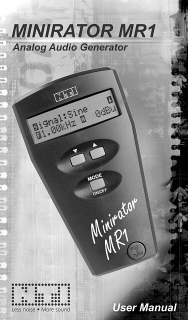
MINIRATOR MR1
MINIRATOR MR1
MINIRATOR MR1

Create successful ePaper yourself
Turn your PDF publications into a flip-book with our unique Google optimized e-Paper software.
<strong>MINIRATOR</strong> <strong>MR1</strong><br />
Analog Audio Generator<br />
User Manual
NTI CONTACT<br />
NTI AG<br />
Im alten Riet 102<br />
9494 Schaan<br />
Liechtenstein, Europe<br />
Tel. +423 - 239 6060<br />
Fax +423 - 239 6089<br />
E-mail info@nt-instruments.com<br />
Home www.nt-instruments.com<br />
© NTI AG<br />
All rights reserved.<br />
Subject to change without notice.<br />
Release 2.01 / Aug 2005<br />
Minirator & Minstruments are registered trademarks of NTI.<br />
2
TABLE OF CONTENT<br />
1. Introduction 4<br />
CE Declaration of Conformity 4<br />
International Warranty & Repair 5<br />
Warnings 6<br />
Overview 7<br />
Test Certificate 7<br />
Battery Replacement 8<br />
2. Basic Operation 9<br />
Getting Started 10<br />
Power On/Off, Low Battery 10<br />
Choose Waveform 12<br />
Change Frequency 13<br />
Change RMS Level 13<br />
Setup Display 14<br />
Connections 15<br />
3. TECHNICAL SPECIFICATION 18<br />
3
Introduction<br />
1. INTRODUCTION<br />
Congratulations and thank you for buying NTI’s Minirator<br />
<strong>MR1</strong>, a product specially suited for professional audio applications.<br />
We are convinced you will enjoy using it!<br />
NTI products are manufactured in compliance with the highest<br />
quality standards and marked with the CE sign.<br />
In order to avoid any damage to the unit, we strongly recommend<br />
to read the entire manual before you start using<br />
the instrument.<br />
CE Declaration of Conformity<br />
We, the manufacturer<br />
NTI AG<br />
Im alten Riet 102<br />
9494 Schaan<br />
Liechtenstein, Europe<br />
hereby declare that the product Minirator <strong>MR1</strong>, released in<br />
1998, conforms to the following standards or other normative<br />
documents:<br />
EMC-Directives: 89/336, 92/31, 93/68<br />
Harmonized Standards: EN55103-1, EN55103-2<br />
This declaration becomes void in case of any changes on<br />
the product without written authorization by NTI.<br />
Date: 1.4.2000<br />
Signature:<br />
Position of Signatory: CEO<br />
4
Introduction<br />
International Warranty & Repair<br />
International Warranty<br />
NTI guarantees the Minirator and its components against<br />
defects in material or workmanship for a period of one year<br />
from the date of original purchase, and agrees to repair or<br />
to replace at its discretion any defective unit at no cost for<br />
either parts or labor during this period.<br />
Restrictions<br />
This warranty does not cover damages caused through accidents,<br />
misuse, lack of care, the attachment or installation<br />
of any components that were not provided with the product,<br />
loss of parts, connecting the instrument to a power supply,<br />
input signal voltage or connector type other than specified, or<br />
wrongly polarized batteries. In particular, no responsibility is<br />
granted for special, incidental or consequential damages.<br />
This warranty becomes void if servicing or repairs of the<br />
product are performed by any party other than an authorized<br />
NTI service center or if the instrument has been opened in<br />
a manner other than specified in this manual.<br />
No other warranty, written or verbal, is authorized by NTI.<br />
Except as otherwise stated in this warranty, NTI makes no<br />
representation or warranty of any kind, expressed or implied<br />
in law or in fact, including, without limitation, merchandising<br />
or fitting for any particular purpose and assumes no<br />
liability, either in tort, strict liability, contract or warranty for<br />
products.<br />
Repair of your Minirator <strong>MR1</strong><br />
In case of malfunction, take - or ship prepaid - your NTI<br />
Minirator, packed in the original box, to the authorized NTI<br />
representative in your country. For contact-details please see<br />
the NTI web page www.nt-instruments.com.<br />
Be sure to include a copy of your sales invoice as prove of<br />
purchase date. Transit damages are not covered by this<br />
warranty.<br />
5
Warnings<br />
Introduction<br />
In order to avoid any problems and damages, follow the<br />
rules listed below:<br />
• Read this manual thoroughly before you operate the<br />
instrument for the first time.<br />
• Use the instrument for the intended purpose only.<br />
• Never connect the instrument to a voltage output such<br />
as a power amplifier, mains power plug, etc.<br />
• Do not disassemble the instrument.<br />
• Never use the instrument in a damp environment.<br />
• Remove the batteries as soon as they are flat or if<br />
the instrument is not intended to be used for a longer<br />
period of time.<br />
• Before you connect the Minirator to an input, verify<br />
that level and frequency are in an acceptable range<br />
for the device. Line signals such as guitar inputs may<br />
only be operated to a max. level of 500 mV (-6 dBV),<br />
suitable frequency for a first test is around 1 kHz.<br />
• If you have headphones or loudspeakers connected,<br />
make sure that the volume control is set to a very low<br />
level to avoid damages to speakers or ears.<br />
• Microphone inputs require low levels of approx.<br />
1 mV only. Make sure that the level is set accordingly<br />
before you connect the Minirator to such inputs.<br />
• Very low and very high frequency signals at high<br />
levels may cause damages to the input of the device<br />
under test.<br />
• High sound pressure levels can cause permanent<br />
damages to your hearing system. Make sure that all<br />
faders of the mixing console are set to minimum to<br />
avoid overloading inputs or giving very loud levels.<br />
6
Overview<br />
Introduction<br />
The Minirator <strong>MR1</strong> is the first member of a family of<br />
miniaturized battery powered audio instruments, called<br />
Minstruments. It is a professional, multifunctional analog<br />
audio signal generator that fits in the palm of your hand.<br />
It covers most of the typical test signals used in a professional<br />
audio environment:<br />
• Sinusoidal Signal, 20 Hz - 20 kHz,<br />
• Frequency Sweep, 20 Hz - 20 kHz<br />
• Square Signal, 20 Hz - 5 kHz<br />
• White Noise<br />
• Pink Noise<br />
• Polarity Test Signal<br />
Over the entire audio band the output level ranges from<br />
the lowest microphone levels in the microvolts range up to<br />
studio reference levels.<br />
The user interface is simple and intuitive with three buttons<br />
only. A short instruction of the Minirator control can also be<br />
found on the rear side of the instrument.<br />
Test Certificate<br />
The Minirator <strong>MR1</strong> is fully tested to the manufacturer's<br />
specifications. We recommend to calibrate and adjust the<br />
Minirator <strong>MR1</strong> in one (1) yearly intervals.<br />
7
Introduction<br />
Battery Replacement<br />
After unpacking, insert<br />
two batteries into the<br />
battery compartment.<br />
• Hinge out the XLR<br />
connector by pressing<br />
the thumb on the<br />
release button. Turn<br />
out the gripped plug<br />
until it locks in the<br />
open position.<br />
8<br />
Fig 1 Insertion of batteries<br />
• Open the battery compartment flap with your fingernails<br />
or any appropriate tool.<br />
• Insert two 1.5 V AA size alkaline batteries as shown in<br />
Fig 1. The direction is labeled on the rear side of the<br />
instrument.<br />
• Close the battery compartment flap.<br />
Notes • We do not recommend to use NiCd or NiMh<br />
rechargeable batteries.<br />
• Do not insert batteries of different types.<br />
• Note the correct polarities of the inserted<br />
batteries. Wrongly polarized batteries may<br />
cause permanent damages to the electronics<br />
inside!<br />
• Remove the batteries as soon as they are<br />
flat.
Basic Operation<br />
2. BASIC OPERATION<br />
LC Display<br />
Down-<br />
button for<br />
parameter<br />
settings<br />
Retractable XLR output<br />
connector, balanced.<br />
Push the release button<br />
and turn to fold out. Push<br />
and turn to retract.<br />
9<br />
RCA (Cinch)<br />
output, unbalanced<br />
Up-button<br />
for<br />
parameter<br />
settings<br />
MODE button, push<br />
once to switch on. Press<br />
to toggle to the next parameter.<br />
Press and hold for<br />
2 sec to switch off.<br />
Fig 2 Instrument overview
Getting Started<br />
Basic Operation<br />
For better understanding, the words MODE, UP and DOWN<br />
refer to the three corresponding keys, whilst the dot matrix<br />
type icons (e.g. (Signal), (Frequency), (Amplitude, Level),<br />
...) refer to the selectable parameters in the display.<br />
Power On/Off, Low Battery<br />
The MODE-key provides<br />
the on/off functions.<br />
• Press the MODE-key<br />
Fig 3 Power-up screen<br />
to switch on.<br />
• The start-up screen appears shortly after showing the<br />
serial number of your Minirator <strong>MR1</strong>, see Fig 3.<br />
• Hold the MODE-key pressed for about two seconds to<br />
switch the device off again.<br />
Furthermore Minirator features an Auto Power OFF function<br />
that automatically switches off the instrument after a<br />
selectable duration of inactivity. Refer to 2.8.a Define the<br />
Auto Power Off Time.<br />
Notes • Minirator reverts all values to the last active<br />
status when powered on.<br />
• If exposed to very high electrostatic<br />
discharges, the instrument might loose<br />
control (e.g. no display). In such a case,<br />
switch the instrument off and on again.<br />
The Minirator features a low battery status indicator,<br />
displaying the end of the battery lifetime, see below Fig 4.<br />
A pulsing vertical block<br />
becomes visible at the<br />
right top corner of the<br />
display, reminding to<br />
replace the batteries.<br />
Fig 4 Low battery indicator<br />
10
Display<br />
Basic Operation<br />
The display shows either<br />
the signal parameter<br />
screen, Fig 5, or the setup<br />
screen, Fig 6.<br />
Fig 5 Default values<br />
In the parameter screen<br />
the waveform, frequency<br />
and level may be altered.<br />
The setup screen allows Fig 6 Setup display<br />
the change of setup parameters.<br />
By selecting the arrow-symbol in the right top corner<br />
and pressing the corresponding arrow-key you may switch<br />
from one to the other screen.<br />
After initialization, the instrument will re-enter the last active<br />
status prior switching off the last time.<br />
To re-enter factory settings, as shown in Fig 5 and Fig 6<br />
switch the Minirator <strong>MR1</strong> on with pressing the UP- and<br />
MODE-key simultaneously.<br />
Keypad<br />
The Minirator has only<br />
two basic rules:<br />
• Each time you press the MODE-key you will move to<br />
the next selectable item. The currently selected item is<br />
indicated by a flashing, inverted first character. In Fig 7<br />
the letter is selected, represented graphically by gray<br />
color.<br />
• To alter the parameter use the UP- and DOWN-keys.<br />
The changed parameter becomes immediately effective.<br />
The signal setting cycles through the available values<br />
while amplitude and frequency stop at their maximum<br />
and minimum values.<br />
MODE-, UP- and DOWN-key provide a repeat function if<br />
you keep them pressed.<br />
11<br />
Fig 7 Selectable items
Choose Waveform<br />
Select the -sign with the MODE-key and toggle through<br />
the available waveforms using the UP- or DOWN-key. The<br />
available waveforms are listed in below Table 1.<br />
Waveform Frequency Description<br />
Sine 20 Hz -<br />
20 kHz<br />
Pure, low distortion sinusoidal<br />
waveform defined by frequency and<br />
level (RMS) in the display. This is the<br />
most common waveform in the audio<br />
world for measurements of frequency<br />
response, distortion, etc.<br />
Sweep The output signal is sequentially<br />
stepped through all the available<br />
frequencies. Step duration can<br />
be adjusted. Actual frequency is<br />
displayed. Sweep starts automatically<br />
indicated by the rotating bar .<br />
W. Noise White noise signal with 20 kHz bandwidth.<br />
Use this signal in conjunction<br />
with a spectrum analyzer (FFT<br />
analyzer).<br />
P. Noise Pink Noise signal with 20kHz<br />
bandwidth. Signal level decreases<br />
with 10 dB/decade (3 dB/octave).<br />
Use this waveform in conjunction with<br />
swept narrow band filters for auditive<br />
(aural) testing.<br />
Square 20 Hz -<br />
5 kHz<br />
Basic Operation<br />
Square wave signal with 50% duty<br />
cycle and no DC offset.<br />
Pol Test 20 Hz Proprietary polarity test fix frequency<br />
of 20Hz.<br />
12
Change Frequency<br />
Basic Operation<br />
The frequency range of the instrument covers the entire<br />
audio range from 20Hz to 20kHz in 31 1/3 rd octave steps.<br />
20 Hz 25 Hz 30 Hz 40 Hz 50 Hz 65 Hz 80 Hz 100 Hz<br />
125 Hz 160 Hz 200 Hz 250 Hz 315 Hz 400 Hz 500 Hz 630 Hz<br />
800 Hz 1 kHz 1.25 kHz 1.60 kHz 2.00 kHz 2.5 kHz 3.15 kHz 4.00 kHz<br />
5.00 kHz 6.30 kHz 8.00 kHz 10.0 kHz 12.5 kHz 16.0 kHz 20.0 kHz<br />
Select the -sign with the MODE-key and toggle through<br />
the frequencies using the UP- or DOWN-key.<br />
Note • The frequency may not be altered in<br />
waveforms Sweep, Pink Noise, White Noise<br />
and PolTest.<br />
Change RMS Level<br />
To change the level of the generated signal, toggle with the<br />
MODE-key, until the -character is flashing and increase<br />
or decrease the level with the UP- or DOWN-key.<br />
Waveform Unit Range Increment<br />
Sine, Square,<br />
White Noise,<br />
Sweep<br />
Table 2 Frequency table for sinusoidal signals<br />
dBu<br />
dBV<br />
Volts<br />
Pol Test dBu<br />
dBV<br />
Volts<br />
Pink Noise dBu<br />
dBV<br />
Volts<br />
-76 dBu - +6 dBu<br />
-78 dBV - +4 dBV<br />
0.13 mV - 1.6 V<br />
-76 dBu - +4 dBu<br />
-78 dBV - +2 dBV<br />
0.13 mV - 1.25 V<br />
-56 dBu - -4 dBu<br />
-58 dBV - -6 dBV<br />
1.25 mV - 500 mV<br />
13<br />
2 dBu<br />
2 dBV<br />
~±23%<br />
2 dBu<br />
2 dBV<br />
~±23%<br />
2 dBu<br />
2 dBV<br />
~±23%<br />
Table 3 Level ranges and increments for signals and units
Setup Display<br />
• Select the -sign.<br />
• Press the DOWN-key<br />
to reach the setup<br />
screen.<br />
Basic Operation<br />
• To revert to the signal parameter screen, select the -<br />
sign and press the UP-key.<br />
a. Define the Auto Power Off Time<br />
Minirator features an auto power off function, switching the<br />
instrument off after a certain period of no key-press. The<br />
default setting is 10 minutes. To alter the auto power off<br />
time select with the MODE-key the -sign, Pwrsave. The<br />
power off time may be decreased by using the DOWN-key or<br />
increased with the UP-key and is immediately active.<br />
Available settings:<br />
10 minutes [10min], 30 minutes [30min],<br />
60 minutes [60min] and OFF [Off]<br />
In the OFF mode, the instrument remains active until the<br />
batteries are flat by not switching off the <strong>MR1</strong> manually.<br />
b. Change Level Units<br />
Select the -sign with the MODE-key and toggle through<br />
the available units using the UP- or DOWN-key. The new<br />
unit is immediately active. The default unit is dBu.<br />
Available settings:<br />
Volts [V], logarithmic level dB Volts [dBV],<br />
logarithmic level dB unit [dBu]<br />
14<br />
Fig 8 Setup display
Basic Operation<br />
c. Change Sweep Speed<br />
In the sweep mode the <strong>MR1</strong> automatically sweeps through<br />
the audio band by stepping through all the available 1/3<br />
octave frequencies as per Table 2. The user may define the<br />
sweep speed by setting the duration of each frequency. To<br />
alter the sweep speed select the -sign with the MODE-key<br />
and toggle through the available settings using the UP- or<br />
DOWN-key.<br />
Available sweep increment settings:<br />
50 milliseconds [50m], 500 milliseconds [.5s],<br />
1 second [1s], 2, 3, 4 and 5 seconds<br />
The new sweep speed is immediately active. At the beginning<br />
of each cycle, a 1kHz start tone remains active twice<br />
as long as the step duration defined. A running sweep is<br />
indicated by a rotating bar in top right corner of the signal<br />
parameter screen.<br />
Connections<br />
Minirator features two output connectors, an unbalanced<br />
RCA (Cinch or Phono plug) output and a balanced, groundfree<br />
XLR connector. The RCA output is permanently active,<br />
whilst the XLR pins are only connected in the folded out<br />
position.<br />
Note • Never connect both outputs simultaneously,<br />
it may cause short circuits.<br />
a. Balanced / Unbalanced Connections<br />
Use balanced connections via the retractable XLR output<br />
pins whenever a balanced input is available, especially for<br />
low level input signals such as microphone inputs and for<br />
longer cables. Balanced connections have the advantage of<br />
a far better noise and hum immunity.<br />
Unbalanced connections are advised if the input of the<br />
device is unbalanced such as inputs of HiFi amplifiers and<br />
low cost mixers.<br />
15
Basic Operation<br />
b. RCA Output<br />
The RCA, also called phono connector<br />
or cinch connector, is located<br />
on the top of the instrument, see Fig<br />
9. It provides the selected output<br />
signal in an unbalanced mode with<br />
a nominal output impedance of<br />
200 ohm. The center pin carries<br />
the signal (hot), and the screen<br />
is the ground. The RCA output is<br />
always active regardless of the XLR<br />
connectors position.<br />
c. XLR Output<br />
The XLR output is a balanced signal output with nominal<br />
200 ohm output impedance, see Fig 10. The XLR pins are<br />
retractable in order to protect the pins from inadvertent connections<br />
and short circuits. To flip the connector out, push the<br />
release button and turn the XLR output whilst pressing. For<br />
example press a finger into the notch on the rotator, see Fig<br />
11. To retract the pins, simply press again the release button<br />
and turn the pins back.<br />
16<br />
Fig 9 RCA output<br />
Fig 10 XLR output Fig 11 Open the XLR output
The XLR pin<br />
assignment,<br />
see Fig 12, is<br />
internationally<br />
standardized.<br />
Basic Operation<br />
17<br />
Pin 1 (silver)<br />
Fig 12 Pin assignment<br />
Pin 2 (gold)<br />
Pin 3 (gold)<br />
• Pin 1 (silver plated, left hand side) is connected to the<br />
cable screen only and is the reference for pin 2 and pin<br />
3 with balanced loads.<br />
• Pin 2 (gold plated, right hand side) provides the signal<br />
with positive polarity.<br />
• Pin 3 (gold plated, center) provides the signal with negative<br />
polarity.<br />
The difference of the signals (pin2-pin3) results in the balanced<br />
signal of doubled amplitude, see below Fig 13. Each<br />
of the semi outputs has a source impedance of 100 ohm,<br />
corresponding to 200 ohm in balanced mode.<br />
Fig 13 Balanced output diagram
Technical Specification<br />
3. TECHNICAL SPECIFICATION<br />
Outputs Balanced XLR, unbalanced RCA,<br />
phantom power resistant<br />
Waveforms Sinusoidal, Square, White Noise,<br />
Pink Noise, Polarity<br />
Frequency Range 20 Hz - 20 kHz in 31 steps (Sine)<br />
20 Hz - 5 kHz in 25 steps (Square)<br />
Frequency Sweep 20 Hz ... 20 kHz with sinusoidal signals<br />
Sweep Speed 0.05, 0.5, 1, 2, 3, 4, 5 sec. per step<br />
Units dBu, dBV, V selectable<br />
Level Ranges Waveform Range Inc<br />
Sine, Square -76 dBu to +6 dBu 2 dBu<br />
White Noise -78 dBV to +4 dBV 2 dBV<br />
Sweep 0.13 mV to 1.6 V ±23%<br />
Pol Test -76 dBu to +4 dBu 2 dBu<br />
-78 dBV to +2 dBV 2 dBV<br />
0.13 mV to 1.25 V ±23%<br />
Pink Noise -56 dBu to -4 dBu 2 dBu<br />
-58 dBV to -6 dBV 2 dBV<br />
1.25 mV to 0.5 V ±23%<br />
Flatness ±0.5 dB<br />
Accuracy ±0.5 dB<br />
THD+N
Quick Guide<br />
Minirator <strong>MR1</strong><br />
F<br />
MODE<br />
On / Off (2 sec)<br />
Select with Select with<br />
MODE