NATURAL GAS CONVERSION KIT - Char-Broil Grills
NATURAL GAS CONVERSION KIT - Char-Broil Grills
NATURAL GAS CONVERSION KIT - Char-Broil Grills

You also want an ePaper? Increase the reach of your titles
YUMPU automatically turns print PDFs into web optimized ePapers that Google loves.
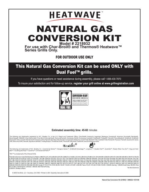
<strong>NATURAL</strong> <strong>GAS</strong><strong>CONVERSION</strong> <strong>KIT</strong>Model # 2218932For use with <strong>Char</strong>-<strong>Broil</strong>® and Thermos® HeatwaveSeries <strong>Grills</strong> Only.FOR OUTDOOR USE ONLYThis Natural Gas Conversion Kit can be used ONLY withDual Fuel grills.If you have questions or need assistance during assembly, please call 1-888-430-7870To insure your satisfaction and for follow-up service, register your grill online at www.grillregistration.comEstimated assembly time: 45-60 minutesThe following are trademarks registered by W.C. Bradley Co. in the U.S. Patent and Trademark Office: <strong>Char</strong>-<strong>Broil</strong>®; America's Legendary Barbeque Company®; American Gourmet®; Bandera®;BrushHawg®; CB940®; <strong>Char</strong>-Diamonds®; <strong>Char</strong>-<strong>Broil</strong> <strong>Char</strong>coal/Gas®; DiamondFlame®; Everybody <strong>Grills</strong>®; Everybody Outside®; FastStart®; Fireball®; Firenzy®; FlavorMaster®; Grill2Go®; Grill2Go®Express®; Grill Lovers®; H20 Smoker®; Keepers of the Flame®; New Braunfels Smoker Company®; Oklahoma Joe's®; Patio Bistro®; Patio Caddie®; Patio Kitchen®; Precision Flame®; Quantum®; SantaFe®; Sear and Grill®; Sierra®; Signature Series®; The Big Easy®; The Minute Grill®; Trentino®; Wild West Tradition®; and the following marks:The following are trademarks of W.C. Bradley Co.: Commercial Series; Designer Series; Grill2Go® Advantage; Longhorn; Double Chef; QuickSet; Ready When You Are; Hog and YardBird; You Bring the Party; SureFire; Universal Grill PartsTEC is a trademark of Tec Infrared <strong>Grills</strong>.® ®Protected under one or more of the following U.S. Patents: 4,989,579; 5,421,319; 5,458,309; 5,579,755; 5,996,573; 6,114,666; 6,135,104; 6,209,533; 6,279,566; 6,331,108; 6,484,900; 6,526,876; 6,595,197; 6,640,799; 6,640,803; 6,729,873; 6,739,473;6,749,424; 6,863,100; 6,935,327; 6,951,213; 6792,935; 7,047,590; D364,535; D372,637; D373,701; D377,735; D383,035; D397,910; D405,643; D406,005; D406,009 ; D413,043; D413,229; D414,982; D415,388; D416,164; D416,441; D417,587;D417,588; D422,516; D423,876; D428,303; D430,772; D435,396; D436,004; D438,059; D438,060; D438,427; D439,110; D442,505; D443,179; D443,354; D443,464; D447,384; D447,385; D447,909; D448,610; D448,614; D448,615; D448,616;D448,975; D449,492; D450,544; D451,759; D454,028; D454,031; D455,205; D455,206; D456,202; D456,222; D456,223; D457,789; D458,520; D458,760; D458,802; D459,088; D459,148 D459,149; D459,161; D459,163; D459,586; D459,943;D460,312; D460,313; D460,318; D461,359; D465,123; D465,693; D466,307; D466,439; D466,752; D473,414; D474,371; D477,498; D477,501; D477,504; D477,506; D477,746; D478,471; D478,472; D480,914; D491,410; D494,009; D494,413;D498,523; D500,359; D504,048; D530,098; D535,000; Canada: 87,743; 87,744; 97,504; 99,355; 102,037; 104,200; 2,315,567; 2,336,036; France: 010,231; 010,422; 010,590; 010,849; 1,089,646; Germany: 1,089,646; South Korea: 384,565; China:99,127,066.5; United Kingdom: 2,099,402; 1,089,646. Other Patents Pending.© 2008 W.C. Bradley CompanyTM REVISION 00© 2008 <strong>Char</strong>-<strong>Broil</strong>, LLC • Columbus, GA 31902 • Printed in USA • Assembly Instructions © 2008Natural Gas Conversion Kit 2218932 • 3499222 •10/31/08
TABLE OF CONTENTSFor Your Safety . . . . . . . . . . . . . . . . . . . . . . . . . . . . . . . . . . . . . . 2Safety Symbols. . . . . . . . . . . . . . . . . . . . . . . . . . . . . . . . . . . . . . 2Installation Safety Precautions . . . . . . . . . . . . . . . . . . . . . . . . . . 3Food Safety . . . . . . . . . . . . . . . . . . . . . . . . . . . . . . . . . . . . . . . . 3Use and Care. . . . . . . . . . . . . . . . . . . . . . . . . . . . . . . . . . . . . 4-11Parts List/ Parts Diagram . . . . . . . . . . . . . . . . . . . . . . . . . . . . . 12Main Burner Assembly. . . . . . . . . . . . . . . . . . . . . . . . . . . . . 13-18Natural Gas Hose Conversion. . . . . . . . . . . . . . . . . . . . . . . . . .19Sideburner Conversion. . . . . . . . . . . . . . . . . . . . . . . . . . . . . 20-27Troubleshooting. . . . . . . . . . . . . . . . . . . . . . . . . . . . . . . . . . . . . 28Call Grill Service Center for Help and Parts• To order non-warranty replacement parts or accessoriesplease visit us on the web at www.charbroil.com or call1-800-888-7870 and one of our friendly and knowledgeableagents will be glad to assist you.Safety SymbolsThe symbols and boxes shown below explain what each headingmeans. Read and follow all of the messages found throughoutthe manual.WARNINGWARNING: Indicates an potentially hazardous situationwhich, if not avoided, could result in death or serious injury.CAUTIONCAUTION: Indicates a potentially hazardous situation orunsafe practice which, if not avoided, may result in minoror moderate injury.2DANGERDANGER: Indicates an imminently hazardous situationwhich, if not avoided, will result in death or serious injury.USE AND CARENatural Gas Connections and Service RegulatorsAbove 1/2 psi.Prior to 1998, all residual gas service regulators wereset with an outlet pressure of 7 inches water column.In the 1998 edition of NFPA 54, the National Fuel GasCode, a change was made allowing service regulatorsof 2 and 5 psi.With this change it was also required that an in lineregulator be connected between the service regulatorand the appliance regulator if the 2 or 5 psi system isused. This additional regulator is not supplied with theproduct.It is possible for a consumer, making the connectionthemselves, or a plumber, not checking, to tap into a 2or 5 psi line. If a pressure of 2 psi or greater is suppliedto the appliance regulator on certain grills it will shutdown and not deliver any gas to the grill. Otherconcerns are the quick disconnect socket and hosewhich are only rated to 1/2 psi.If the quick disconnect socket, hose, and grill areproperly connected and still not getting gas, deliverypressure needs to be verified. If pressure is greaterthan 1/2 psi, make sure that an in line regulator ispresent.Once the grill has been over-pressured, the regulatormay or may not have been damaged. The best practiceis to replace the regulator.CAUTION:Read and follow all safety statements, assemblyinstructions, and use and care directions before attemptingto assemble and cook.INSTALLER/ASSEMBLER:Leave this manual with consumer.CONSUMER:Keep this manual for future reference.WARNING:Failure to follow all manufacturer’s instructions could resultin serious personal injury and/or property damage.CAUTION:Some parts may contain sharp edges – especially as notedin the manual! Wear protective gloves if necessary.
WARNINGCALIFORNIA PROPOSITION 651. Combustion by-products produced when usingthis product contain chemicals known to the State ofCalifornia to cause cancer, birth defects, and otherreproductive harm.2. This product contains chemicals, including leadand lead compounds, known to the State ofCalifornia to cause cancer, birth defects or otherreproductive harm.Wash your hands after handling this product.Installation Safety Precautions• Use grill, as purchased, only with LP (propane) gas and theregulator/valve assembly supplied. A conversion kit must bepurchased for use with natural gas.• Grill installation must conform with local codes, or in theirabsence of local codes, with either the National Fuel GasCode, ANSI Z223.1/ NFPA 54, Natural Gas and PropaneInstallation Code, CSA B149.1, or Propane Storage andHandling Code, B149.2, or the Standard for RecreationalVehicles, ANSI A 119.2/NFPA 1192, and CSA Z240 RV Series,Recreational Vehicle Code, as applicable.• All electrical accessories (such as rotisserie) must beelectrically grounded in accordance with local codes, orNational Electrical Code, ANSI / NFPA 70 or CanadianElectrical Code, CSA C22.1. Keep any electrical cords and/orfuel supply hoses away from any hot surfaces.• This grill is safety certified for use in the United States and/orCanada only. Do not modify for use in any other location.Modification will result in a safety hazard.DANGERIf you smell gas:1. Shut off gas to the appliance.2. Extinguish any open flame.3. Open lid.4. If odor continues, keep away from theappliance and immediately call your gassupplier or your fire department.CAUTIONFor residential use only. Do not use for commercialcooking.WARNINGDo not attempt to repair or alter thehose/valve/regulator for any “assumed” defect. Anymodification to this assembly will void your warrantyand create the risk of a gas leak and fire. Use onlyauthorized replacement parts supplied bymanufacturer.Food SafetyFood safety is a very important part of enjoying the outdoorcooking experience. To keep food safe from harmful bacteria,follow these four basic steps:Clean: Wash hands, utensils, and surfaces with hot soapy waterbefore and after handling raw meat and poultry.Separate: Seperate raw meats and poultry from ready-to-eatfoods to avoid cross contamination. Use a clean platter andutensils when removing cooked foods.Cook: Cook meat and poultry thoroughly to kill bacteria. Use athermometer to ensure proper internal food temperatures.Chill: Refrigerate prepared foods and leftovers promptly.For more information call: USDA Meat and Poultry Hotlineat 1-800-535-4555 in Washington, DC (202) 720-3333,10:00 am-4:00 pm .CAUTIONUsing pots larger than 6 quarts in capacity couldexceed weight limit of theside burner shelf,resulting in failureof grill cartcomponents.WARNING1. Do not store or use gasoline or otherflammable liquids or vapors in the vicinity ofthis or any other appliance.2. An LP cylinder not connected for use shall notbe stored in the vicinity of this or any otherappliance.3
USE AND CAREDANGERNEVER store a spare cylinder under or near the applienceor in an enclosed area.Never fill a cylinder beyond 80% full.LP CylinderThe LP cylinder used with your grill must meet the followingrequirements:1. Use LP cylinders only with these required measurements: 12”(30.5cm) (diameter) x 18” (45.7cm) (tall) with 20 lb. (9kg) capacitymaximum.2. LP cylinders must be constructed and marked in accordance withspecifications for LP cylinders of thr U.S. Department ofTransportation (DOT) or for Canada, CAN/CSA-B339, cylinders,spheres and tubes for transportation of dangerous goods.Transport Canada (TC). See cylinder collar for marking.3. LP cylinder valve must have:-Type 1 outlet compatable withregulator or grill.-Safety relief valve.-UL listed Overfill ProtectionOPD Hand WheelDevice (OPD). This OPD safetyfeature is identified by a unique triangular hand wheel. Use onlyLP cylinders equipped with this type of valve.4. LP cylinder must be arranged for vapor withdrawal and includecollar to protect LP cylinder valve. Always keep LP cylinder inupright position during use, transit or storage.An over filled or improperly stored cylinder is a hazard dueto possible gas release from the safety relief valve.f you see, smell or hear gas escaping, immediately getaway from the LP cylinder/appliance and call your firedepartment.This could cause an intense fire with risk of propertydamage, seriouse injury or death.LP Cylinder Removal, Transport and Storage1. Turn OFF all control knobs and LP cylinder valve. Turncoupling nut counterclockwise by hand only - do not use toolsto disconnect. Loosen cylinder screw beneath bottom shelf,then lift LP cylinder up and out of cart. Install safety cap ontoLP cylinder valve. Always use cap and strap supplied withvalve. Failure to use safety cap as directed may result inserious personal injury and/or property damage.2. A disconnected LP cylinder instorage or beingLP Cylinder Valvetransported must have a safety capinstalled (as shown). Do not store an LPcylinder in enclosed spaces such as acarport, garage, porch, covered patio orother building. Never leave an LP cylinderinside a vehicle which may become overheatedby the sun.SafetyCapRetainer Strap3. Do not store an LP cylinder in an area where children play.LP cylinder in upright position for vapor withdrawalLP (liquefied Petroleum Gas)LP gas is nontoxic, odorless and colorless when produced. ForYour Safety, LP gas has been given an odor (similar to rottencabbage) so that it can be smelled.LP gas is highly flammable and may ignite unexpectedly whenmixed with air.LP Cylinder FillingUse only licensed and experienced dealers.LP dealer must purge new cylinder before filling.Dealer should NEVER fill LP cylinder more than 80% of LPcylinder volume. Volume of propane in cylinder will vary bytemperature.A frosty regulator indicates gas overfill. Immediately close LPcylinder valve and call local LP gas dealer for assistance.Do not release liquid propane (LP) gas into the atmosphere.This is a hazardous practice.To remove gas from LP cylinder, contact an LP dealer or call alocal fire department for assistance. Check the telephonedirectory under “Gas Companies” for nearest certified LPdealers.4
LP Cylinder ExchangeMany retailers that sell grills offer you the option of replacingyour empty LP cylinder through an exchange service. Use onlythose reputable exchange companies that inspect, precision fill,test and certify their cylinders. Exchange your cylinder onlyfor an OPD safety feature-equipped cylinder as described inthe “LP Cylinder” section of this manual.Always keep new and exchanged LP cylinders in upright positionduring use, transit or storage.Leak test new and exchanged LP cylinders BEFOREconnecting to grill.LP Cylinder Leak TestFor your safetyLeak test must be repeated each time LP cylinder is exchangedor refilled.Do not smoke during leak test.Do not use an open flame to check for gas leaks.Grill must be leak tested outdoors in a well-ventilated area, awayfrom ignition sources such as gas fired or electrical appliances.During leak test, keep grill away from open flames or sparks.Use a clean paintbrush and a 50/50 mild soap and watersolution. Brush soapy solution onto areas indicated by arrows infigure below.Do not use household cleaning agents. Damage to gas traincomponents can result.Connecting Regulator to the LP Cylinder1. LP cylinder must be properly secured onto grill. (Refer toassembly section of your grill manual).2. Turn all control knobs to the OFF position.3. Turn LP cylinder OFF by turning hand wheel clockwise to aFull Stop.4. Remove the protective cap from LP cylinder valve. Always usecap and strap supplied with valve.Safety Relief ValveOffClockwiseStrap and CapOPD Hand WheelType 1 outlet withthread on outsideDo not use a POL transportplug (plastic part with externalthreads)! It will defeat thesafety feature of the valve.5. Hold regulator and insert nipple into LPcylinder valve. Hand-tighten thecoupling nut, holding regulator in astraight line with LP cylinder valve soas not to cross-thread the connection.WARNINGNipple has to be centeredinto the LP cylinder valve.If “growing” bubbles appear do not use or move theLP cylinder. Contact an LP gas supplier or your firedepartment!5
StraightHold coupling nut and regulatoras shown for proper connectionto LP cylinder valve.Connecting Regulator to the LP Cylinder (Con’t.)6. Turn the coupling nut clockwise and tighten to a Full Stop.The regulator will seal on the back-check feature in the LPcylinder valve, resulting in some resistance. An additionalone-half to three-quarters turn is required to complete theconnection. Tighten by hand only - do not use tools.NOTE:If you cannot complete the connection, disconnect regulator andrepeat steps 5 and 6. If you are still unable to complete theconnection, do not use this regulator!Leak Testing Valves, Hoses and Regulator1. Turn all control knobs to the OFF position.2. Be sure regulator is tightly connected to LP cylinder.3. Completely open LP cylinder valve by turning hand wheelcounterclockwise. If you hear a rushing sound, turn gas offimmediately. There is a major leak at the connection. Correctbefore proceeding.4. Brush soapy solution onto areas circled below.Never remove threaded orificeat end of valve during leaktesting of valves.DANGERDo not insert any tool or foreign object into the valve outletor safety relief valve. You may damage the valve andcause a leak. Leaking propane may result in explosion,fire, severe personal injury, or death.WARNINGOutdoor gas appliance is not intended to be installed inor on a boat.Outdoor gas appliance is not intended to be installed inor on an RV.Never attempt to attach this grill to the self-contained LPgas system of a camper trailer or motor home.Do not use grill until leak-tested.If a leak is detected at any time, STOP and call the firedepartment.If you cannot stop a gas leak IMMEDIATELY close LPcylinder valve and call LP gas supplier or your firedepartment!5. If “growing” bubbles appear there is a leak. Close LP cylindervalve immediately and retighten connections. If leaks cannotbe stopped do not try to repair. Call for replacement parts.Order new parts by giving the serial, model number and nameand part number of items needed (see parts list) to the GrillService Center at 1-888-430-7870.6. Always close LP cylinder valve after performing leak test byturning hand wheel clockwise.6
WARNINGFor Safe Use of Your Grill and to Avoid SeriousInjury:-Do not let children operate or play near grill.-Keep grill area clear and free from materials that burn.-Do not block holes in sides or back of grill.-Check burner flames regularly.-Use grill only in well-ventilated space. NEVER use inenclosed space such as carport, garage, porch, coveredpatio, or under an overhead structure of ant kind.-Do not use charcoal or ceramic briquets in a gas grill.(Unless briquets are supplied with your grill)-Use grill at least 3 ft. from any wall or surface.Maintain 10ft. clearance to objects that can catch fir orsources of ignition such as pilot lights on water heaters,live electrical appliances, etc.Apartment Dwellers:Check with apartment management to learn therequirements and fire codes for using an LP gas grill inyour apartment complex. If allowed, use outside on theground floor with a three (3) foot clearance from walls orrails. Do not use on or under balconies.NEVER attempt to light burner with lid closed. Abuildup of non-ignited gas inside a closed grill ishazardous.Never operate grill with LP cylinder out of correctposition specified in assembly instructions.Always close LP cylinder valve and remove couplingnut before moving LP cylinder from specifiedoperation position.Safety Tips- Before opening LP cylinder valve, check the coupling nut fortightness.- When grill is not in use, turn off all control knobs and LP cylindervalve.- Never move grill while in operation or still hot.- Use long-handled barbecue utensils and oven mitts to avoidburns and splatters.- Maximum load for sideburner and side shelf is 10 lbs.- The grease tray must be inserted into grill and emptied aftereach use. Do not remove grease tray until grill has completelycooled.- Clean grill often, preferably after each cookout. If a bristle brushis used to clean any of the grill cooking surfaces, ensure noloose bristles remain on cooking surfaces prior to grilling. It isnot recommended to clean surfaces while grill is hot.- If you notice grease or other hot material dripping from grill ontovalve, hose or regulator, turn off gas supply at once. Determinethe cause, correct it, then clean and inspect valve, hose andregulator before continuing. Perform a leak test.- Keep ventilation openings in cylinder enclosure (grill Cart) freeand clean of debris.- Do not store objects or materials inside the grill cart enclosurethat could block the flow of combustion air to the underside ofeither the control panel or the firebox bowl.- The regulator may make a humming or whistling noise duringoperation. This will not affect safety or use of grill.- If you have a grill problem see the “Troubleshooting Section” ofyour grill manual.- If the regulator frosts, turn off grill and LP cylinder valveimmediately. This indicates a problem with the cylinder and itshould not be used on any product. Return to supplier!CAUTIONPutting out grease fires by closing the lid is not possible.<strong>Grills</strong> are well ventilated for safety reasons.Do not use water on a grease fire. Personal injury mayresult. If grease fire develops, turn knobs and LP cylinderoff.Do not leave grill unattended while preheating or burningoff food residue on Hi. If grill has not been regularlycleaned, a grease fire can occur that may damage theproduct.Main Burner Ignitor LightingDo not lean over grill while lighting.1. Turn OFF all Gas Burner Control Valves.2. Turn ON gas source or tank.3. Open lid during lighting.4. To ignite turn burner control valve to .5. Once burner has ignited (use flame viewing ports on front ofcontrol panel to verify ignition), turn knob to desired setting.6. If ignition does not occur in 5 seconds, turn the burner controlsOFF, wait 5 minutes, and repeat the lighting procedure.7. Ignite remaining burners by repeating steps 4 through 6 foreach burner.Lighting instructions continued on next page.7
8WARNINGTurn controls and gas source or tank OFF when notin use.CAUTIONIf ignition does NOT occur in 5 seconds, turn the burnercontrols OFF, wait 5 minutes and repeat the lightingprocedure. If the burner does not ignite with the valveopen, gas will continue to flow out of the burner and couldaccidently ignite with risk of injury.Main Burner Match-LightingDo not lean over grill while lighting.1. Open lid during lighting.2. Place match into match holder (hanging from side of cart).Light match, place into lighting hole on right or left side offirebox.3. Push in and turn far right or far left knob to position. Besure burner lights and stays lit.4. If ignition does not occur in 5 seconds, turn the burner controlknob OFF, wait 5 minutes, and repeat the lighting procedure.5. Light other burners by pushing knob in and turning toposition.Side Burner Ignitor LightingWarning:Top cover must be openwhen side burner(s) is inoperation.Do not lean over grill while lighting.1. Turn OFF all Gas Burner Control Valves.2. Turn ON gas source or tank.3. To ignite side burner, open side burner cover.4. Turn side burner knob to , to ignite burner.5. Once burner has ignited, turn knob to desired setting.6. If side burner does not light, turn knob to OFF, wait 5minutes, and repeat the lighting procedure.Side Burner Match-Lighting1. Open lid during lighting. Turn ongas at LP cylinder.2. Place lit match near burner.3. Turn side burner knob to .Burner Flame CheckRemove cooking grates and troughs. Light burners, rotate knobsfrom to . You should see a bigger flame inposition than seen on . Perform burner flame check on sideburner, also. Always check flame prior to each use. If only lowflame is seen refer to “Sudden drop or low flame” in theTroubleshooting Section of your grill manual.Turning Grill OffTurn all knobs to OFF position. Turn LP cylinder off byturning hand-wheel clockwise to a full stop.Ignitor CheckTurn Gas OFF at LP cylinder. Press and hold electronic ignitorbutton. “Click” should be heard and spark seen each timebetween collector box or burner and electrode. See“Troubleshooting” in your grill manual if no click or spark.Valve CheckIMPORTANT: Make sure gas is OFF at LP cylinder beforechecking valves. Knobs lock in OFF position. To check valves,first push in knobs and release, knobs should spring back. Ifknobs do not spring back, replace valve assembly before usinggrill. Turn knobs to LOW position then turn back to OFF position.Valves should turn smoothly.Hose CheckBefore each use, check to see if hoses are cut or worn. Replacedamaged hoses before using grill. Use only valve/hose/regulatorspecified by manufacturer.General Grill CleaningDo not mistake brown or black accumulation of grease andsmoke for paint. Interiors of gas grills are not painted at thefactory (and should never be painted). Apply a strong solutionof detergent and water or use a grill cleaner with scrub brush oninsides of grill lid and bottom. Rinse and allow to completely airdry. Do not apply a caustic grill/oven cleaner to paintedsurfaces.Plastic parts: Wash with warm soapy water and wipe dry. Donot use citrisol, abrasive cleaners, degreasers or a concentratedgrill cleaner on plastic parts. Damage to and failure of parts canresult.Porcelain surfaces: Because of glass-like composition, mostresidue can be wiped away with baking soda/water solution orspecially formulated cleaner. Use non-abrasive scouring powderof stubborn stains.Painted surfaces: Wash with mild detergent or non-abrasivecleaner and warm soapy water. Wipe dry with a soft nonabrasivecloth.Stainless steel surfaces: To maintain your grill’s high qualityappearance, wash with mild detergent and warm soapy waterand wipe dry with a soft cloth after each use. Baker-on greasedeposits may require the use of an abrasive plastic cleaning pad.Use only in direction of brushed finish to avoid damage. Do notuse abrasive pad on areas with graphics.Cooking surfaces: If a bristle brush is used to clean any of thegrill cooking surfaces, ensure no loose bristles remain oncooking surfaces prior to grilling. It is not recommended to cleancooking surfaces while grill is hot.
CAUTIONSPIDER ALERT!SPIDER AND WEBSINSIDE BURNER TUBECleaning the Burner AssemblyFollow these instructions to clean and/or replace parts of burnerassembly or if you have trouble igniting grill.1. Turn gas OFF at control knobs and LP cylinder.2. Remove cooking grates and flame tamers.3. Remove screws and carryover tubes from rear of burners.4. Remove screw and washers to disengage burner from bracketon firebox.5. Remove screws to detach electrode from burner. Electrodeshould remain in firebox.6. Carefully lift each burner up and away from valve openings.If you notice that your grill is getting hard to light or that theflame isn’t as strong as it should be, take the time to check andclean the venturi’s.CONTROL PANELWe suggest three ways to clean the burner tubes. Use the oneeasiest for you.A. Bend a stiff wire (a light weight coat hanger works well)into a small hook. Run the hook through each burnerseveral times.VALVESPIDER WEBSINSIDE VENTURIIn some areas of the country, spiders or small insects have beenknown to create “flashback” problems. The spiders spin webs, buildnests and lay eggs in the grill’s venturi tubes(s) obstructing the flow ofgas to the burner. The backed-up gas can ignite in the venturi behindthe control panel. This is known as a flashback and it can damageyour grill and even cause injury.To prevent flashbacks and ensure good performance the burner andventuri assembly should be removed from the grill and cleaned beforeuse whenever the grill has been idle for an extended period.Storing Your Grill-Clean cooking grates.-Store in a dry location.-When LP cylinder is connected to grill, store outdoors in awell-ventilated space and out of reach of children.-Cover grill if stored outdoors. Choose from a variety of grillcovers offered by manufacturer.-Store grill indoors ONLY if LP cylinder is turned off anddisconnected, removed from grill and stored outdoors.-When removing grill from storage, follow “Cleaning theBurner Assembly” instructions before starting grill.B. Use a narrow bottle brush with a flexible handle (do notuse a brass wire brush), run the brush through eachburner tube several times.C. Wear eye protection: Use an air hose to force air into theburner tube and out the burner ports. Check each port tomake sure air comes out each hole.7. Wire brush entire outer surface of burner to remove foodresidue and dirt.8. Clean any blocked ports with a stiff wire such as an open paperclip.9. Check burner for damage, due to normal wear and corrosionsome holes may become enlarged. If any large cracks or holesare found replace burner.VERY IMPORTANT: Burner tubes mustre-engage valve openings.See illustration at right.BurnerCorrectburner-to-valveengaement10. Attach electrode to burner.11. Carefully replace burners.12. Attach burners to brackets on firebox.13. Reposition carryover tubes and attach to burners. Replaceflame tamers and cooking grates.Electrode9
This unit should be hard plumbed using components thatmeet National Fuel Gas Code.WARNINGDo not use flexible gas hose supplied for Drop-in Models.Connecting Your Grill to the Natural Gas Source.4. When the quick disconnect socket and the gas hose are connected,a valve in the socket opens automatically to permit full gas flow.When the gas hose is disconnected, the valve in the socket instantlyand positively shuts off the flow of gas. Because the valve in thesocket positively shuts off the flow of gas, the grill can bedisconnected from the gas source by disconnecting the gas hosefrom the quick disconnect socket. The socket should be left attachedto the gas source (house piping). Figure C, below, shows properlyconnected hose and socket.1. A professionally-installed shut-off valve between the supply pipingand the socket is recommended, but not required, by the NationalFuel Gas Code. Socket connection must be made outdoors.2. Coat the gas supply pipe nipple with gas resistant pipe dope orapproved teflon tape. Screw socket onto gas supply pipe (house gassource) as shown in Figure A below, and wrench-tighten.CAUTIONThe quick disconnect socket should never be connectedto the grill. Direction of gas flow is indicated on thesocket.Quick disconnect socketHouse pipingFigure CWith proper assembly, the gas hose cannot be removed withoutpushing the quick disconnect sleeve back. To disconnect, pushsleeve back and pull plug out of sleeve (this automatically shuts offgas).Please Note: Hose and assembly are C.S.A. listed for natural gas,manufactured gas, mixed gas and for liquefied petroleum and forLP Gas-Air mixtures on basis of 0.64 specific gravity for 1000BTU’s per cubic foot of gas at 0.3 in. water column pressure drop.Only ANSI Z21.54 approved hoses should be used with this grill.Figure A3. Pull back the sleeve on the quick disconnect socket and insert theunattached end of the gas hose into the socket. Release the sleeveand continue pushing the hose into the socket until the sleeve snapsinto the locked position. See Figure B.The appliance and its individual shut off valve must bedisconnected from the gas supply piping system during anypressure testing on that system at test pressures in excess of 1/2psig (3.5kPa).The appliance must be isolated from the gas supply piping systemby closing its individual manual shutoff valve during any pressuretesting of the gas supply piping system at test pressures equal toor less than 1/2 psi (3.5kPa).Gas hoseSleeveFigure BWARNINGDo not use hard metal piping of any kind to connect thistype of grill to natural gas source. Use only hosespecified by manufacturer. Using hard metal piping orconvoluted metal tubing is an unsafe practice. Movementof the grill can cause breakage of metal pipe.10
Leak Testing1. Turn all grill control knobs to OFF.2. Be sure gas hose is tightly connected to gas source.3. Completely open gas source. If you hear a rushing sound, turngas off immediately. There is a major leak at the connection.Correct before proceeding.4. Brush soapy solution onto area circled below.CAUTIONCAUTION: Sideburner lid must be open when sideburneris in operation, if so equipped.Burner Flame Check• Remove cooking grates and flame tamers. Light burners,rotate knobs from HIGH to LOW. You should see a smallerflame in low position than seen on HIGH. Perform burner flamecheck on sideburner also. Always check flame prior to eachuse. If only low flame is seen refer to "Sudden drop or lowflame" in the Troubleshooting Section.HIGHLOW5. If “growing” bubbles appear, there is a leak. Close gassource immediately and tighten connection. If leaks cannotbe stopped do not try to repair. Call for replacement parts.Order new parts by giving the serial, model number and nameof items needed to the Grill Service Center at 1-800-241-7548(USA) or 1-800-387-6057 (Canada).6. Always close gas source after performing leak test.Safety TipssWhen grill is not in use, turn off all control knobs and gassource.Hose Check• Before each use, check to see if hoses are cut, worn or kinked.Replace damaged hoses before using grill. Use onlyvalve/hose/regulator specified by manufacturer.NormalHoseKinkedHoseTools required for assembly:Orifice Removal Tool - ProvidedAdjustable Wrench - Not providedStandard #2 Phillips Screwdriver - Not providedNOTE: Magnetic tip screwdrivers are recommended, but not required.Estimated assembly time: 45-60 minutes11
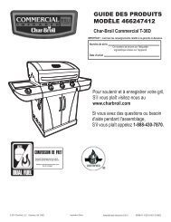
PARTS LIST/DIAGRAMNote: Illustrations are not to scale.Key Qty. Description Part No.A . . . . . 4 . . . . . Main Burner Natural Gas Bezel. . . . . . . . . . . . . . . . . . . . . . . . . . . . . . . . . . . . . . . . . . . . 80007876B . . . . . 1 . . . . . Sideburner Natural Gas Bezel. . . . . . . . . . . . . . . . . . . . . . . . . . . . . . . . . . . . . . . . . . . . . 80007877C . . . . . 1 . . . . . Orifice Driving Tool . . . . . . . . . . . . . . . . . . . . . . . . . . . . . . . . . . . . . . . . . . . . . . . . . . . . 80004378D . . . . . 1 . . . . . 10 ft., 3/8” Natural Gas Hose . . . . . . . . . . . . . . . . . . . . . . . . . . . . . . . . . . . 3496263E . . . . . 3 . . . . . Main Burner NG Orifice - 3 Burner Grill (Black Dot- #54) . . . . . . . . . . . . . . . . . . . . . 80007767F. . . . . 3 . . . . . Main Burner NG Orifice - 3 Burner Grill (No Color Dot- #56) . . . . . . . . . . . . . . . . . . 3499617G . . . . 1 . . . . . Sideburner/Griddle NG Orifice (Red Dot-1.45mm) . . . . . . . . . . . . . . . . . . . . . . . . . .80007768H . . . . 4 . . . . .#8 x3/8” Self-Tapping Screw . . . . . . . . . . . . . . . . . . . . . . . . . . . . . . HAB016038CPNBDA B CBlack DotNo Color DotRed DotDEFGH12
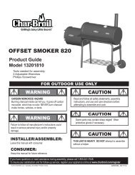
Main Burner Conversion1- First, make sure all control knobs are in the OFF position, LP tank valve is closed, and tank is disconnected from regulator andremoved from grill.- Next, open Lid and remove Warming Rack, Cooking Grates, and Troughs.Your Grill may differ from illustrations shown. This manual covers 3 & 4 burner grills, use picturesas reference only.Warming RackCooking Grates(3 or 4 depending on Unit purchased)TroughTroughNOTE: Grill lid is shownremoved for clarity. DO NOTremove the grill lid.2Remove Burners- Remove screws from each burner assembly. There are four (4) screws per burner assembly.- Lift each burner assembly up and out of the firebox.FireboxRemove BurnerAttachmentScrews(4 per burner)Burnersshown in place.(4 burner grill shown.)Lift andremoveburnerassemblyfromfirebox.13
Main Burner Conversion (Cont.)3Install Screws in Burner Venturi Tube- Locate the screw hole in the burner assembly venturi tube.- Install one #8x3/8” self-tapping screw into the venturi tube screw hole. Screw should be threaded completely into the hole.- Repeat for all burner assemblies.- Lay burner assemblies aside.Burner assemblyScrew HoleInstall #8x3/8”Self-TappingScrew intoscrew hole. Threadscrew COMPLETELYinto the screw hole.Burner Venturi Tube4Remove LP tank Heat Shield- Open the cabinet doors. Remove any stored items from the cabinet.- Using a #2 Phillips screwdriver, remove the two #8x3/8” screws that attach the LP Tank Heat Shield to the door brace. Note: The rear of theLP Tank Heat Shield is held in place with tabs and slots.- Holding the front of the LP Tank Heat Shield, rotate it down and pull it forward to disengage the rear tabs from the back panel.- Place the LP Tank Heat Shield on the bottom shelf for storage.Door BraceLP TankHeat Shield14Remove 2 #8x3/8”screws from LP TankHeat Shield.NOTE: Cabinet doors are shownremoved to enhance clarityDO NOT remove cabinet doorsLP TankHeat ShieldIn StoredPosition
Main Burner Conversion (Cont.)5Remove LP Orifices- DO NOT completely remove the orifices at this point.- Insert the Orifice Driving Tool provided with Kit into the Firebox Burner opening, engage the tool with the orifice, and loosen each orifice 1-2turns, counter-clockwise, from its orifice holder.FireboxFirebox BurnerOpeningOrifice Driving ToolOrificeTop view of 3 burner firebox withburner assemblies removed.Firebox BurnerOpening6Remove LP Orifices- Using your fingers in the area illustrated below, unscrew each orifice by hand.- Save the removed orifices for converting back to LP gas.OrificeUsing your fingers,turn the orificecounter-clockwiseto remove.OrificeHolderOrificeHolderBracket15
Main Burner Conversion (Cont.)7Install Natural Gas (NG) Orifices- Using your fingers, thread the Main Burner NG Orifices into each orifice holder 2-3 turns, clockwise. Do not fully tighten the orifices at this time.- If your grill is a 3 Burner Black & Gray lid grill use Main Burner NG Orifice - 3 Burner Grill (Black Dot- #54)- If your grill is a 3 Burner Stainless lid grill use Main Burner NG Orifice - 3 Burner Grill (No Color Dot- #56)OrificeUsing your fingers,thread the orifice intothe orifice holder twoturns. (Clockwise)OrificeHolder8Install Natural Gas (NG) Orifices- Insert the Orifice Driving Tool into the Firebox Burner opening, and engage the orifice with the tool.- Tighten each orifice securely, turning it clockwise. NOTE: Tighten the orifice sufficiently to prevent gas leakage. DO NOT over-tightenDo not use any tool other than the Orifice Driving Tool!FireboxFirebox BurnerOpeningOrifice Driving ToolOrificeTop view of 3 burner firebox withburner assemblies removed.Engage the OrificeDriving Tool withthe orifice16
Main Burner Conversion (Cont.)9Reinstall Burners- Place all burner assemblies into place in the firebox, align the burner assembly screw holes with the mating holes in the firebox.- Carefully insert the #8x3/8” screws through the burner assembly and into the firebox. Insert 4 screws per burner assembly.- Using a #2 Phillips screwdriver, not provided, barely tighten each screw. DO NOT over-tighten the burner attachment screws. These screwsare used to hold the burner in place. Overtightening will cause problems later when attempting to clean your grill.Install BurnerAttachmentScrews(4 per burner)FireboxNOTE:Do not over-tightenthe burnerattachmentscrews.Burners shown in place.10Replace Main Burner Bezels and Control KnobsNOTE: REPLACE ONE BEZEL AT A TIME. DO NOT REMOVE ALL THE BEZELS AT THE SAME TIME.- Pull the Tube Burner Control Knobs off of Valve Stems.- Remove screws and washers that secure each Bezel to the Control Panel. Save removed Bezels for converting back to LP Tank Gas.- Install new Natural Gas Bezels provided with Kit (see illustration below) in place of old Bezels onto Control Panel, and secure using previouslyremoved screws and washers. Assure proper alignment with control knob before fully tightening. Note: New bezels will change the rotationfor the control knob to properly control ignition and flames for your grill.- Press Control Knobs back onto Valve Stems. Make adjustments needed to Bezels for free movement of Control Knobs.ScrewsValveStemBezelsNatural Gas Bezel80007876NOTE: Replace only onebezel at a time!Main BurnerControl Knobs17
Main Burner Conversion (Cont.)11Reinstall LP Tank Heat Sheild- Insert tabs without screw holes(at rear of heat shield) into back panel slots.- Align the tabs with screw holes at the front of the heat shield to the cross brace.- Carefully insert the #8x3/8” screws through the tabs and into the cross brace.- Using a #2 Phillips screwdriver, not provided, tighten both screws. DO NOT over-tighten the screws.Tabs withoutscrewholes atrear of HeatShield.Tabs withscrewholes atfront of HeatShield.Insert screws through front tabsand into door brace,then tighten.Door brace.Insert Tabsinto Slots.LP Tank HeatShield in place.18
Natural Gas Hose Conversion12- Manifold connection is located on the right hand side and toward the front and inside of the cart.- Using a wrench, not provided, remove LP Regulator Hose Assembly from Manifold Connection. Save removed LP Manifold Connection forconverting back to LP Tank Gas.6ManifoldConnectionLP RegulatorHose AssemblyCabinet doors shown removedfor clarity. DO NOT removecabinet doors.13- Secure the Natural Gas Hose Assembly using a wrench, not provided, to Manifold Connection.ManifoldConnectionNatural GasHose AssemblyIf you have a model with a sideburnerproceed to “Sideburner Conversion”on page 2019
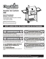
Sideburner ConversionNOTE: Your Grill will have one of the TWO sideburner styles shown in this manual. Check your grill to make sure youfollow the correct assembly steps. The assembly steps for the second style of sideburner begins on page 25.14- Open the sideburner cover. Remove the cooking grate. (Sideburner cover not shown for clarity.)6- Pull the sideburner control knob off the valve stem. Remove the existing bezel by removing the two screws securing bezel to shelf fascia. Savethe bezel for converting back to LP gas. Save screws for reuse.- Removing these screws will cause the gas valve to disengage from the back of the shelf fascia. This is normal.Griddle (If equipped)Cooking GrateScrewsBezelValveStemSideburnerControl KnobMain BurnerControl KnobShelf Fascia15- Remove the burner cap retainer clip. Pull down on clip from underneath the burner and pull it out through the center of the burner.- Remove the burner cap and wind diverter by lifting up from the burner.6STYLE 1 SideburnerBurner CapWind DiverterPull down on clipfrom underneathburnerRemove clipthrough center ofburnerBurnerBurner CapRetainer Clip20
Sideburner Conversion (Cont.)16- Remove the ignitor wire from the electrode. Shown in view “A”6- Remove the two burner mounting screws and washers from the side shelf pan. Shown in view “B”- Lift up the burner to disengage the stud from it’s locating hole and maneuver the burner out of the side shelf pan. Shown in view “C”NOTE: The convoluted gas tubing is flexible and will allow sufficient clearance to complete this conversion. DO NOT twist or crimp theConvoluted (flexible) Gas Tubing. To do so may result in gas leakageABLocating StudElectrode5mm SiliconeWasher#10 Lock Washer#10-24x3/8” ScrewsCRemove Ignitorwire fromElectrodeRemove Burnerfrom side burner pan17- Locate the Sideburner Venturi underneath the sideburner shelf. The Sideburner Venturi will be suspended by the convoluted gas tubing.Carefully position the Sideburner Venturi so that you can access the Orifice Holder Bracket screws- Using a Phillips Screwdriver, remove two #5-40 screws from the Orifice Holder Bracket. Save these screws for reassembly later.- After removing the #5-40 screws, CAREFULLY pull Orifice Holder Bracket away from the Sideburner Venturi as shown in detail #1.NOTE: The convoluted gas tubing is flexible and will allow sufficient clearance to complete this conversion. DO NOT twist or crimp theConvoluted (flexible) Gas Tubing. To do so may result in gas leakage.6SideburnerVenturiSideburnerVenturi#5-40ScrewsConvoluted (Flexible)Gas TubingOrificeHolderBracketOrificeSideburnerValveView from below sideburner shelf.Convoluted (Flexible)Gas TubingDetail #1OrificeHolderBracket21
Sideburner Conversion (Cont.)18- Using a Phillips Screwdriver, not provided, remove the 4 sideburner pan screws.- Remove the sideburner pan by lifting it straight up.- At this point the orifice holder will be loose and more convenient to work with.NOTE: DO NOT twist or crimp the Corrugated Gas Tubing. To do so may result in gas leakage.6Orifice HolderBracketView from back corner of side shelf19- Using an adjustable wrench, not provided, place the wrench securely on the Orifice Holder in the area shown below.- While holding the adjustable wrench firmly, use the Orifice Driving Tool to loosen and remove the Orifice by turning it counter-clockwise. 6- Thread the new Orifice, Sideburner NG Orifice (Red Dot- 1.45mm), into the Orifice Holder by hand.- While holding the adjustable wrench firmly on the Orifice Holder, Tighten the Orifice with the Orifice Driving Tool by turning it clockwise. Tightenthe orifice sufficiently to prevent gas leakage.DO NOT use any tool other than the Orifice Driving Tool to tighten the Orifice.Orifice HolderBracketOrifice HolderOrifice - turncounter-clockwiseto remove.Orifice DrivingToolPlace adjustable wrenchhere while removing Orifice.22
Sideburner Conversion (Cont.)20- With the new Orifice installed into the Orifice Holder, push the Orifice Holder Bracket onto the Sideburner Venturi.- Align the screw hole in the Orifice Holder Bracket and Sideburner Venturi, and using a Phillips Screwdriver, reinstall the #5-40 screw.NOTE: The convoluted Gas Tubing is flexible and will allow sufficient clearance to complete this conversion. DO NOT twist or crimp theCorrugated Gas Tubing. To do so may result in gas leakage.6SideburnerVenturi#5-40 ScrewOrificeCorrect orifice- to-venturiengagement.#5-40ScrewsOrificeHolderBracketConvolutedGas Tubing#5-40 ScrewOrificeHolderBracketSideburnerValveView from below sideburner shelf.21- Install the Sideburner pan with the 4 sheet metal screws removed previously. Tighten screws only enough to secure sideburner pan. Shown A.6- Carefully manuever the burner into position. Shown (B)NOTE: The convoluted Gas Tubing is flexible and will allow sufficient clearance to complete this step. DO NOT twist or crimp the CorrugatedGas Tubing. To do so may result in gas leakage.- Reinstall 2 #10-24X3/8” screws and washers through sideburner pan and into burner. Shown C.ABCReinstall theSideburner PanLocating Stud5mm Silicone Washer#10 Lock Washer#10-24x3/8” ScrewsReinstall Burnerto side burner pan23
Sideburner Conversion (Cont.)22- Place side burner wind diverter over side burner aligning cutout- Place burner cap onto side burner and attach side burner cap clip. Shown B.- Place sideburner cooking grate onto side burner shelf, aligning grate legs with holes in shelf shown A.6AGriddle (If equipped)Cooking GrateBLocked PositionBurner CapRetainer Clip24
Sideburner Conversion (Cont.)NOTE: Steps 23 through 26 apply to style 2 sideburner. Disregard these steps if you have a style 1 sideburner.23- Open the sideburner cover. Remove the cooking grate. (Sideburner cover not shown for clarity.)6- Pull the sideburner control knob off the valve stem. Remove the existing bezel by removing the two screws securing bezel to shelf fascia. Savethe bezel for converting back to LP gas. Save screws for reuse.- Removing these screws will cause the gas valve to disengage from the back of the shelf fascia. This is normal.Griddle (If equipped)Cooking GrateScrewsBezel ValveStemSideburnerControl KnobShelf FasciaMain BurnerControl Knob24- Remove the wingnut from the burner, Shown A.- Remove the Ignitor wire from the electrode, Shown B.- Remove the burner from the sideburner pan, Shown C.AC6SideburnerWingnutCBWingnutElectrodeSideburnerignitorWireNOTE: Sideburner lid not shown for clarity.25
Sideburner Conversion (Cont.)25- Locate the Sideburner Valve underneath the sideburner shelf. The Sideburner Valve will be attached to the Sideburner Fascia.- Using the supplied Orifice Driving Tool, remove the orifice from the sideburner valve as shown below.- This style Sideburner is designed to work with Natural Gas once Orifice is removed. Do not replace any Orifices when using Natural Gas.6BBOrificeOrifice DrivingToolSideburner ValveSideburner Fascia26- Reinstall the burner, Shown A.- Make sure the burner tube is properly aligned with the sideburner valve, Shown B.- Reinstall the wingnut to the burner stud. Attach the ignitor wire to the electrode. Shown C.6ASideburnerBBurner tubeValveBProper AlignmentCWingnutElectrodeSideburnerignitor wireNOTE: Sideburner lid not shown for clarity.26
Sideburner Conversion (Cont.)27- Place sideburner cooking grate onto side burner shelf, aligning grate legs with holes in shelf. Shown A.6Griddle (If equipped)ACooking Grate28 NOTE: Step 28 applies to both styles of sideburner. You must perform this step in order to complete your grill conversion.FOR SIDEBURNER UNITS: Use bezel part number 80007877.- While holding the sideburner valve from the back of the shelf fascia, align the screw holes in the bezel, shelf fascia and valve.- Install screws previously removed. Assure proper alignment with control knob before fully tightening the screws. Tighten screws with a #2 Phillipsscrewdriver.- Press the Control Knob back onto the valve stem.ScrewsBezel ValveStemSideburnerControl KnobSideburner Natural Gas Bezel80007877Shelf FasciaMain BurnerControl Knob27
EMERGENCIES: If a gas leak cannot be stopped, or a fire occurs due to gas leakage, call the fire department.EmergenciesGas leaking fromcracked/cut/burnedhose.Possible Cause• Damaged hose.Prevention/Solution• Turn off gas at at source. If anything but burned, replace parts. Ifburned, discontinue use of product until a plumber has investigatedcause and corrections are made.TroubleshootingProblemBurner(s) will not lightusing ignitor.Possible Cause<strong>GAS</strong> ISSUES:• No gas flow.Prevention/Solution• Make sure gas hose is properly connected to grill. If hose isproperly connected, make sure gas source is turned on.Burner(s) will notmatch light.• See “<strong>GAS</strong> ISSUES:” .• Match will not reach.• Improper method of match-lighting.• Use long-stem match (fireplace match).• See “Match-Lighting” section of Grill Use and Care.Flames blow out.• Natural gas valve not fully open.• Open Natural Gas Valve to full open position.• Inadequate gas pressure.• Call gas company.<strong>Char</strong>-<strong>Broil</strong>, LLC ® Columbus, GA 31902 Assembly Instructions © 2008 28