DGE Linear Actuators - Allied Automation, Inc.
DGE Linear Actuators - Allied Automation, Inc.
DGE Linear Actuators - Allied Automation, Inc.

Create successful ePaper yourself
Turn your PDF publications into a flip-book with our unique Google optimized e-Paper software.
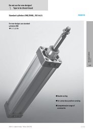
<strong>DGE</strong> <strong>Linear</strong> <strong>Actuators</strong>Belt and Ball Screw DrivenBelt Driven <strong>Linear</strong> <strong>Actuators</strong> Sizes: 8, 12, 18, 25, 40, 63 Stroke Lengths up to 5 m Maximum Speed: 10 m/s Repeatability of ±0.10 mm Axial force up to 1,500 NBall Screw Driven <strong>Linear</strong> <strong>Actuators</strong> Sizes: 18, 25, 40, 63 Stroke Lengths up to 2 m Maximum Speed: 1.2 m/s Repeatability of ±0.02 mm Axial force up to 1,600 NMulti-axis SystemsComponents and accessories to build: X/Y/Z Axis Systems Cantilever-type Handling Gantries <strong>Linear</strong> Gantries Planar Surface GantriesInfo 130 US
<strong>DGE</strong> Electrical <strong>Linear</strong> <strong>Actuators</strong>Features and BenefitsEnclosed Belt and Ball Screw <strong>Actuators</strong>To maximize uptime and reliabilityin production, <strong>DGE</strong> actuators aredesigned with the mechanical driveenclosed within the body of theactuator. This minimizes yourmaintenance costs by both protectingthe drive mechanism from externalcontamination while retaining anyfactory-installed drive lubricantwithin the actuator.Compact PerformanceThe recirculating ball linear guideused on <strong>DGE</strong> actuators features arugged, wide-track bearing designthat is up to three times widerthan standard linear guides.This wider, more rigid stancegives <strong>DGE</strong> actuators superior loadand moment carrying capability,and enables compact solutions toheavy duty applications.Multi-axis SystemsReduce engineering time and effortwhen designing and assemblingmulti-axis systems, with Festopre-engineered multi-axis connectingkits. Each kit comes complete withall the structural components, adapterplates and assembly hardware tobuild an almost endless array ofmulti-axis systems – each can becustom designed to meet yourspecific application needs.Furthermore, to simplify yourinstallation, Festo offers a completeline of passive guides, sensors,assembly hardware and motormounting kits to readily integratethe rugged and economical <strong>DGE</strong>actuator into your application.Festo...Your <strong>Automation</strong>Partner WorldwideAs a global leader in industrialautomation components andsystems, with over $1.8 billionsales worldwide, Festo hasthe resources and applicationexperience to be your longterm partner for cost-effectiveautomation solutions.• 55 independentsubsidiaries worldwide• Representation in180 countries• Worldwide networking forconsistent standards ofproducts, consultancy,sales and services.• Worldwide support providedby over 11,000 team membersFesto Quality Assurance,ISO 9001 CertificationFesto Corporationis committed toprovide Festoproducts andservices that willmeet or exceedour customers’requirements inproduct quality, delivery,customer service andsatisfaction.All Festo locations within the UnitedStates are registered to ISO 9001.Online LiteratureLiterature in PDF format isavailable for download at:www.festo.com/us/<strong>DGE</strong>
Actuator TechnologyAccessory OverviewTechnology Section 4 Page 125Multi-axis System Connecting Components Section 4.1 Page 129HMVThe multi-axis modular systemincludes different adapter kits forthe assembly of multi-axis systems. Adapter kits for sizes 18 to 63:The connecting components areadjustable to allow for stress-freeaxis alignment.These multi-axis systems can easilybe assembled. X/Y axis tables Cantilever-type handling gantries <strong>Linear</strong> gantries Planar surface gantriesPassive Guide Axes Section 4.2 Page 151, 171FDG-ZR, FDG-SPDriveless linear guide units with guideand freely movable slide. Designed toincrease load and moment capacities inmulti-axis applications.FDG-GA (Dust Proof Version)The guide and slide are protectedagainst particles from above andthesidebymeansofacover. Sizes: 18, 25, 32, 40, 50, 63 Stroke lengths of 1 …5,100 mm,depending on the version Load capacity to max. 14,050 Nor 1,820 Nm Precision, rigid guide, suitable for<strong>DGE</strong>-...-KF Sizes: 25, 32, 40 Stroke lengths of 1 …2,000 mm Load capacity to max. 7,300 N or 330 Nm Standard or extended slide Wide range of options for mountingon drive units System product for handling andassembly technology Optional with additional slide KL/KR Wide range of options for mountingon drive units System product for handling andassembly technology1FDG-RF (With Roller Guide)Precision, rigid guide, suitable for<strong>DGE</strong>-ZR-RF. Sizes: 25, 40, 63 Stroke lengths of 1 …5,000 mm Load capacity to max. 600 N or 600 Nm. Precision, rigid guide, suitable for<strong>DGE</strong>-...-RF Standard slide or extended slide System product for handling andassembly technologyCouplings and Connectors Section 4.3 Page 185Bellows Couplings, KSEThis one-piece coupling is suitablefor force-locked and backlash-freetranmission of low and medium torquebetween electric motors and actuators. Sizes: 15 and 19 mm System product forpositioning aplicationsZero Backlash Couplings, KSEThe three-part coupling is suitable forforce-locked and backlash-freetransmission of high torques betweenelectric motors and actuators.Connecting Shafts, KSKFor slip-free transmission of anidentical feed speed to a secondactuator. Sizes: 30, 40, 65 mm For <strong>DGE</strong> sizes: 25, 40, 63 For synchronization of beltdriven actuators System product forpositioning aplications For torsion-resistanttransmission of torquesMotor Flanges Section 4.4 Page 195MTR-FLTherightmotorflangeforeverymotor axis combination. Contact Festo for motor flangesthat fit your specific motorand application.Accessories and Sensors Section 4.5 Page 199For mounting actuators and theirspecific attachments. Sensors foruseasproximitysignalsandforsafety monitoring. Sensor brackets / Switching lugs Magnetic reed proximity sensors Magneto-resistive proximity sensors Inductive proximity sensors Foot mountings Central supports Emergency buffers Shock absorbers03/2006 – Subject to change – Info 130 USFesto Corporation5
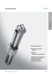
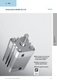
Belt Driven <strong>Linear</strong> <strong>Actuators</strong> For applications requiring positioning repeatability of 0.10 mm Suitable for high-speed applications Speeds of up to 10 m/s are possible Axial loads up to 1,500 N are allowable252.06174<strong>DGE</strong> linear actuatorsencapsulate their mechanicaldrives within the body ofthe actuator. This protectsthem from contamination andprevents premature failure.Wide range of optionsfor third-party motormounting kits.21 Toothed belt2 Drive shaft / trunnion3 Coupling housing4 Aluminum profile5 Drive6 Slide7 Sensors can be integrated3Multi-axis systems for sizes18 to 63 mm. Cantilever-typehandling gantries, lineargantries, planar surfacegantries and X/Y axis tablescan easily be configured.03/2006 – Subject to change – Info 130 USFesto Corporation7
Product OverviewBelt Driven <strong>Linear</strong> <strong>Actuators</strong>Technology Section 2<strong>Actuators</strong> Without Guide <strong>DGE</strong>-ZR Section 2.1 Page 9These actuators are ideal for moving light loads(up to 163 kg); they can be also combined with externallinear guides to move heavy loads or withstand highmoment loads. Sizes: 8, 12, 18, 25, 40, 63 Stroke lengths: 1 … 4,500 mm Max Speed: 5 m/s Repeatability: ±0.1 mm22.0<strong>Actuators</strong> With Recirculating Ball Bearing Guide <strong>DGE</strong>-ZR-KF Section 2.2 Page 25These actuators are used to carry a maximum load ormoment in a compact space. Loads up to 1,433 kg arepossible, as are moments up to 1,820 Nm in pitch and yawand up to 580 Nm in the roll direction.Dust Proof Version<strong>Actuators</strong> with recirculating ball bearing guide. Guide andslide are fitted with a cover to protect against the ingressof particles from above and the side. Sizes: 8, 12, 18, 25, 40, 63 Stroke lengths: 1 … 4,500 mm Max Speed: 3 m/s Repeatability: ±0.1 mm Extended slide available for increased load capacity<strong>DGE</strong>-ZR-KF-GA Sizes: 25, 40 Stroke lengths: 1 … 1,800 mm Max Speed: 3 m/s Repeatability: ±0.1 mm<strong>Actuators</strong> With Roller Guide <strong>DGE</strong>-ZR-RF Section 2.3 Page 45These actuators feature internal roller guides for maximumdynamic response with a minimum of noise. High cyclespeeds make these actuators fast and economical. Sizes: 25, 40, 63 Stroke lengths: 1 … 5,000 mm Max Speed: 10 m/s Repeatability: ±0.1 mm Extended slide available for increased load capacity Self lubricating, no additional lubrication required fo first 10,000 km<strong>Actuators</strong> With Heavy-duty Guide (Dual Ball Bearing Guide) <strong>DGE</strong>-ZR-HD Section 2.4 Page 57Used in applications where you need the lowest profilepossible to withstand high moment loads. Pitch and yawmoment loads up to 560 Nm are possible, as are rollmoment loads up to 375 Nm. Sizes: 18, 25, 40 Stroke lengths: 1 … 2,000 mm Max Speed: 3 m/s Repeatability: ±0.1 mm Highest roll moment capacityBoom Axes <strong>DGE</strong>A Section 2.5 Page 69Improved dynamics compared to belt driven actuator<strong>DGE</strong>-ZR in cantilever operation, as the motor, gear unitand drive head are securely mounted. Sizes: 18, 25, 40 Stroke lengths: 1 … 1,000 mm Max Speed: 3 m/s Repeatability: ±0.05 mm8 Festo CorporationInfo 130 US – Subject to change – 03/2006
<strong>DGE</strong>-ZR Belt Driven <strong>Linear</strong> <strong>Actuators</strong>22.1Stroke lengths from1 to 4,500 mmActuator without integralguide, for use with externallinear guideWide range of optionsfor third-party motormounting kitsComprehensive range ofmounting accessoriesfor multi-axis combinations03/2006 – Subject to change – Info 130 USFesto Corporation9
Technical Data<strong>DGE</strong>-ZR Belt Driven <strong>Linear</strong> <strong>Actuators</strong>Sizes: 8, 12, 18, 25, 40, 63Stroke Lengths: 1 … 4,500 mm22.1General Technical DataSize 8 12 18 25 40 63DesignElectromechanical actuator with toothed beltGuide– (Designed for use with external guide)Mounting positionAnyWorking stroke 1) [mm] 1 … 650 1 … 1,000 1 … 1,000 1 … 3,000 2) 1 … 4,000 2) 1 … 4,500 2)AppliedloadmSeegraphsonpage13Max. axial force F x [N] 15 30 60 260 610 1,500Max. input torque [Nm] 0.08 0.18 0.5 2.6 9.7 42Max. no-load running torque 3) [Nm] 0.05 0.08 0.2 0.5 1.0 4.5Max. speed [m/s] 1 1.5 2 5 5 5Repeatability [mm] ±0.08 ±0.11) Total stroke = working stroke + 2x stroke reserve (see page 11)2) Special lengths on request3) Measured at a speed of 0.2m/sOperating and Environmental ConditionsSize 8 12 18 25 40 63Ambient temperature [°C] –10 … +40Protection classIP40Weights [kg]Size 8 12 18 25 40 63Basic weight with 0 mm stroke 1) 0.237 0.31 0.862 1.89 6.05 23.2Additional weight per 100 mm stroke 0.05 0.08 0.16 0.32 0.51 1.81) <strong>Inc</strong>luding coupling housingMass Moment of InertiaSize 8 12 18 25 40 63J O [kg cm 2 ] 0.006 0.015 0.064 0.38 2.34 25.6J H per meter stroke [kg cm 2 /m] 0.003 0.009 0.021 0.078 0.45 3.6J L per kg applied load [kg cm 2 /kg] 0.259 0.365 0.685 1 2.53 7.85The total mass moment of inertia J A is calculated as follows: J A =J O +J H xworkingstroke[m]+J L xm applied load [kg]10 Festo CorporationInfo 130 US – Subject to change – 03/2006
Technical Data – Load Values<strong>DGE</strong>-ZR Belt Driven <strong>Linear</strong> <strong>Actuators</strong>Characteristic Load ValuesThe indicated forces and torquesrefer to the center line of the internaldiameter of the profile. They must notbe exceeded in the dynamic range.22.1If the actuator is subjected tomore than two of the indicatedforces and torques simultaneously,the following equations must besatisfied in addition to the indicatedmaximum loads.0.4 × Fz +Mx +My + 0.2 ×Mz ≤ 1Fz max. Mx max. My max. Mz max.FzFz max.≤ 1MzMz max.≤ 1Permissible Forces and TorquesSize 8 12 18 25 40 63Fy max. [N] – – – – – –Fz max. [N] 38 59 120 330 800 1,600Mx max. [Nm] 0.15 0.3 0.5 1 4 8My max. [Nm] 2 4 11 20 60 120Mz max. [Nm] 0.3 0.5 1 3 8 24Second Moment of AreaLyLxSize 8 12 18 25 40 63Lx [mm 4 ] 6.7 x 10 3 19.1 x 10 3 72.3 x 10 3 240 x 10 3 748 x 10 3 6031 x 10 3Ly [mm 4 ] 6.6 x 10 3 19.7 x 10 3 69.8 x 10 3 224 x 10 3 673 x 10 3 5688 x 10 3– Design tool– PtToolSelection and calculation softwarewww.festo.com/en/engineering12 Festo CorporationInfo 130 US – Subject to change – 03/2006
Technical Data – Maximum Acceleration<strong>DGE</strong>-ZR Belt Driven <strong>Linear</strong> <strong>Actuators</strong>Maximum Permissible Acceleration “a” as a Function of Applied Load “m”<strong>DGE</strong>-8<strong>DGE</strong>-12a[m/s 2 ]a[m/s 2 ]m[kg]m[kg]<strong>DGE</strong>-18<strong>DGE</strong>-252a[m/s 2 ]a[m/s 2 ]2.1m[kg]m[kg]<strong>DGE</strong>-40<strong>DGE</strong>-63a[m/s 2 ]a[m/s 2 ]m[kg]m[kg]verticalhorizontal03/2006 – Subject to change – Info 130 USFesto Corporation13
Technical Data – Maximum Support Span<strong>DGE</strong>-ZR Belt Driven <strong>Linear</strong> <strong>Actuators</strong>Maximum Permissible Support Span “l “as a Function of Force “F”The actuator may need to besupported with central supports MUPin order to restrict deflection withlong stroke lengths. The graphs onpage 15 serve to determine themaximum permissible support spanl as a function of the force actingupon the drive F.1 Force on the surface of the slideF xF xF x22 Force on the front of the slideF y F y F y2.114 Festo CorporationInfo 130 US – Subject to change – 03/2006
Technical Data – Maximum Support Span<strong>DGE</strong>-ZR Belt Driven <strong>Linear</strong> <strong>Actuators</strong>Maximum Permissible Support Span “l” (without central support) as a Function of Force “F”<strong>DGE</strong>-8<strong>DGE</strong>-12F[N]F[N]l [mm]l [mm]<strong>DGE</strong>-18<strong>DGE</strong>-2522.1F[N]F[N]l [mm]l [mm]Maximum Permissible Support Span “l” (without central support) as a Function of Force “F“<strong>DGE</strong>-40<strong>DGE</strong>-63F[N]F[N]l [mm]l [mm]1203/2006 – Subject to change – Info 130 USFesto Corporation15
Technical Data – Dimensions<strong>DGE</strong>-ZR Belt Driven <strong>Linear</strong> <strong>Actuators</strong>DimensionsSize 8 … 18<strong>DGE</strong>-8-... only22.1stroke length1 Coupling housing3 Centering hole for footmounting4 Coupling8 Slide in end position of theworking stroke (including L12)9 Stroke reserve, see page 11for descriptionaJ Internal mechanical stopProfileSize 8 Size 12 Size 182 Sensor slot for proximitysensoraJ Not suitable for proximitysensor16 Festo CorporationInfo 130 US – Subject to change – 03/2006
Technical Data – Dimensions<strong>DGE</strong>-ZR Belt Driven <strong>Linear</strong> <strong>Actuators</strong>Size B1 B3 B4 B5 B6 B11 B12 B13 B14 D1 D2 D3 D4 D5 D6 D7∅ ∅ ∅ ∅ ∅[mm] +0.2 ±0.1 g6 H11 H78 20.5 8 16 4 13 7.3 5 – 12 4 2 3.4 4 12 M3 M312 25 8 21 6 18.6 8.7 6.5 22.7 16.2 4 2 3.4 4 16 M3 M318 34 12 28 7 24 7.7 5.5 31.1 22 6 3 5.4 6 19 M5 M4Size D8 D9 D10 D12 H1 H2 H3 H4 H5 H6 H8 H9 H11 J2 L1 L2∅ ∅[mm]g78 17 28.7 3.4 M4 30 26.5 23.1 8 9.8 8.1 11 0 11 1.7 180 9012 19 30 3.4 M4 35.5 32 28.6 10.5 12.5 11.8 11 13.1 11 0.7 216 10818 25 44 5.5 M5 49.8 43.8 37.6 14 17 16.4 15.5 21.8 15.5 0.6 282 141Size L3 L4 L5 L6 L7 L11 L12 L13 L14 L15 L16 T1 T2 T3 T6 T72[mm] ±0.1 +4 ±0.1 ±0.18 30 21 15.5 52 15 4 27.5 27.5 5 9.7 3.2 7 1.1 3.4 0.7 18.812 33 24 17 64 15 4 36.5 29 5 11.3 4.8 7 1.1 3.4 0.8 2918 46 32 23.5 85 30 4 46.5 31.5 5 12.8 5.3 11 1.6 5.7 1.5 192.103/2006 – Subject to change – Info 130 USFesto Corporation17
Technical Data – Dimensions<strong>DGE</strong>-ZR Belt Driven <strong>Linear</strong> <strong>Actuators</strong>DimensionsSize 25 … 63Size 63 Size 25/4022.1stroke length1 Coupling housing3 Centering hole forfoot mounting HP4 Coupling8 Slide in end position of theworking stroke (including L12)9 Stroke reserve, see page 11for descriptionaJ Internal mechanical stopProfileSize 25 Size 40 Size 632 Sensor slot for proximitysensor6 Mounting slot for slot nut NST18 Festo CorporationInfo 130 US – Subject to change – 03/2006
Overview and Ordering Data<strong>DGE</strong>-ZR Belt Driven <strong>Linear</strong> <strong>Actuators</strong>Order CodeMandatory DataNote: See belowDrive shaftright22.1Drive shaftleftLK = No drive shaft on leftLV = Drive shaft on left, frontLH = Drive shaft on left, rearLB=Driveshaftonleft,front and rearRK = No drive shaft on rightRV = Drive shaft on right, frontRH = Drive shaft on right, rearRB=Driveshaftonright,front and rearNote:The insertion point for the proximitysensor is located on the right side ofthe <strong>DGE</strong>-ZR.O=topU=underneathR=rightL=leftV=frontH=rear20 Festo CorporationInfo 130 US – Subject to change – 03/2006
Overview and Ordering Data<strong>DGE</strong>-ZR Belt Driven <strong>Linear</strong> <strong>Actuators</strong>Order CodeOptionsKG = Coupling housingAdapter for mounting the motor on the actuatorKSE =CouplingConnecting element between actuator and motor(For third-party motor mounting kits, see page 196.)MTR-FL =FlangeConnecting element between coupling housing and motor(For third-party motor mounting kits, see page 196.)2B = Mounting slot cover / S = Sensor slot coverFor protection against the ingress of dirt2.1G/H/I/J/N =ProximitysensorsFor use as a proximity signal and for safety monitoringV = Plug socket with cableFor proximity sensorsY = Slot nutFor mounting attachmentsM =CentralsupportFor mounting the actuatorF = Foot mounting kitFor mounting the actuator03/2006 – Subject to change – Info 130 USFesto Corporation21
Ordering Data<strong>DGE</strong>-ZR Belt Driven <strong>Linear</strong> <strong>Actuators</strong>MMandatory DataOOptionsModule No. Design Size Stroke Drive function Drive shaft onleftDrive shaft onrightCouplinghousing193739193740193741193742193743193744<strong>DGE</strong> 812182540631 … 4,500 ZR LKLVLHLBRKRVRHRBKG2OrderingExample193742 <strong>DGE</strong> – 25 – 500 – ZR – LK – RV – KG2.1Ordering TableSize 8 12 18 25 40 63 Conditions Code For info,see pageM Module No. 193739 193740 193741 193742 193743 193744 –Design Electromechanical linear drive <strong>DGE</strong> <strong>DGE</strong>Size 8 12 18 25 40 63 -…Working stroke [mm] 1 … 650 1…1,000 1 … 3,000 1…4,000 1 … 4,500 1 -…10Drive function Electromechanical drive with toothed belt -ZR -ZRDrive shaft on left No drive shaft on left 2 -LKDrive shaft on left, front-LVDrive shaft on left, rear-LH20Drive shaft on left, front and rear-LBDrive shaft on right No drive shaft on right 3 -RKDrive shaft on right, front-RVDrive shaft on right, rear-RH20Drive shaft on right, front and rear-RBO Coupling housing Coupling housing -KG 21Entercode1 Special stroke lengths on request.2 Not available with RK (no drive shaft on right).3 Not available with LK (no drive shaft on left).22 Festo CorporationInfo 130 US – Subject to change – 03/2006
Ordering Data<strong>DGE</strong>-ZR Belt Driven <strong>Linear</strong> <strong>Actuators</strong>OOptionsAccessories Slot cover Slot nut Central support Foot mounting Proximity sensor Plug socketZUB…S…B…Y …M …F …G…H…I…J…N…VZUB – 2S–10Y– –F–2G–2V2Ordering tableSize 8 12 18 25 40 63 Conditions Code For info,see page Accessories Supplied separately ZUB- 199 ZUB-O Slot cover Sensor slot 1…10 …SMounting slot – – – – 1…10 …B205Slot nut for mounting slot – – 1…10 …Y 205Central support 1…10 …M 200Foot mounting (kit) 1…10 …F 200Proximity sensor with cable 2.5 m 1…10 …G(For actuator with plug 1…10 …Hprofile slot) contactless with cable 2.5 m 1…10 …I21, 210contactless, plug 1…10 …JNC contact with cable 2.5 m 1…10 …NPlug socket with cable 2.5 m 1…10 4 …VEntercode2.14 For use with proximity sensors H and J.03/2006 – Subject to change – Info 130 USFesto Corporation23
22.124 Festo CorporationInfo 130 US – Subject to change – 03/2006
<strong>DGE</strong>-ZR-KF Bel t D ri ven L inear <strong>Actuators</strong> wi th Reci rculat ing Ball Beari ng GuideGA: Dust Proof Version22.2GK: Standard SlideStroke lengths from1 to 4,500 mmGuides on these <strong>DGE</strong>s areup to three times widerthan standard width guides,providing superior load andmoment capabilityStandard or extended slideUse when moving mediumto heavy loadsDust proof version<strong>DGE</strong>-ZR-KF-GAWide range of optionsfor third-party motormounting kitsComprehensive range ofmounting accessoriesfor multi-axis combinations03/2006 – Subject to change – Info 130 USFesto Corporation25
Technical Data<strong>DGE</strong>-ZR-KF Belt Driven <strong>Linear</strong> <strong>Actuators</strong> with Recirculating Ball Bearing GuideSizes: 8, 12, 18, 25, 40, 63Stroke lengths: 1 … 4,500 mmGKGA22.2General Technical DataSize 8 12 18 25 40 63DesignElectromechanical actuator with toothed belt and recirculating ball bearing guideGuideRecirculating ball bearing guideMounting positionAnyWorking stroke 1) Standard Slide, GK [mm] 1…650 1 … 1,000 1 … 1,000 1 … 3,000 2) 1 … 4,000 2) 1 … 4,500 2)Extended Slide, GV [mm] – – 1…920 1 … 2,900 1 … 3,830 1 … 4,250Dust Proof Version, GA [mm] – – – 1 … 1,800 1 … 1,800 –Applied load See graphs on pages 30 and 32Max. axial force F x [N] 15 30 60 260 610 1,500Max. input torque [Nm] 0.08 0.18 0.5 2.6 9.7 42Max. no-load running torque 3) [Nm] 0.05 0.08 0.2 0.5 1.0 4.5Max. speed [m/s] 1 1.5 2 3 3 3Repeatability [mm] ±0.08 ±0.11) Total stroke = working stroke + 2x stroke reserve (see page 31)2) Special lengths on request3) Measured at a speed of 0.2 m/sOperating and Environmental ConditionsSize 8 12 18 25 40 63Ambient temperature [°C] –10 … +40Protection classIP40Weights [kg]Size 8 12 18 25 40 63Basic weight with 0 mm stroke 1) Standard Slide, GK 0.32 0.66 1.16 2.6 7.6 30.3Extended Slide, GV – – 1.62 3.52 9.52 40.2Dust Proof Version, GA – – – 3.51 9.67 –Additional weight per GK/GV 0.095 0.14 0.26 0.47 0.94 2.6100 mm stroke GA – – – 0.56 1.06 –Additional slide KL/KR – – 0.25 0.38 1.06 3.11) <strong>Inc</strong>luding coupling housing and slide26 Festo CorporationInfo 130 US – Subject to change – 03/2006
Technical Data<strong>DGE</strong>-ZR-KF Belt Driven <strong>Linear</strong> <strong>Actuators</strong> with Recirculating Ball Bearing GuideMass Moment of InertiaSize 8 12 18 25 40 63J O Standard Slide, GK [kg cm 2 ] 0.025 0.058 0.247 0.81 5.25 50.7Extended Slide, GV [kg cm 2 ] – – 0.355 1.08 7.14 70.9Dust Proof Version, GA [kg cm 2 ] – – – 1.37 8.71 –J H per meter stroke [kg cm 2 /m] 0.003 0.009 0.021 0.078 0.45 3.6J L per kg applied load [kg cm 2 /kg] 0.259 0.365 0.685 1 2.53 7.85The total mass moment of inertia J A is calculated as follows: J A =J O +J H xworkingstroke[m]+J L xm applied load [kg]Toothed BeltSize 8 12 18 25 40 63Tensile stress 1) [%] 0.04 0.1 0.2 0.11 0.1 0.15Pitch [mm] 2 2 2 3 5 8Effective diameter [mm] 10.18 12.09 16.55 20.05 31.83 56.02Feed constant [mm/rev.] 32 38 52 63 100 17621) At max. feed force2.2MaterialsSectional View1 2 3 4 56Actuator1 Return pulley housing Anodized aluminum2 Cover strip Corrosion resistant steel3 Toothed belt Polychloroprene with Glascord and nylon coating4 Profile Anodized aluminum5 Slide Anodized aluminum6 Drive housing Anodized aluminum03/2006 – Subject to change – Info 130 USFesto Corporation27
Technical Data – Load Values<strong>DGE</strong>-ZR-KF Belt Driven <strong>Linear</strong> <strong>Actuators</strong> with Recirculating Ball Bearing GuideCharacteristic Load Values for Actuator with Standard Slide GK or Protected Version GAThe indicated forces and torquesrefer to the center of the guide rail.They must not be exceeded in thedynamic range.22.2If the actuator is subjected tomore than two of the indicatedforces and torques simultaneously,the following equations must besatisfied in addition to the indicatedmaximum loads.Fy+Fz +Mx +My +Mz ≤ 1Fy max. Fz max. Mx max. My max. Mz max.Permissible Forces and TorquesSize 8 12 18 25 40 63Fy max. [N] 255 565 930 3,080 7,300 14,050Fz max. [N] 255 565 930 3,080 7,300 14,050Mx max. [Nm] 1 3 7 45 170 580My max. [Nm] 3.5 9 23 85 330 910Mz max. [Nm] 3.5 9 23 85 330 910Second Moment of AreaLyLxSize 8 12 18 25 40 63Lx [mm 4 ] 16.9 x 10 3 46 x 10 3 172 x 10 3 551 x 10 3 1908 x 10 3 13677 x 10 3Ly [mm 4 ] 7x10 3 21 x 10 3 73.7 x 10 3 250 x 10 3 875 x 10 3 6987 x 10 3– Design tool– PtToolSelection and calculation softwarewww.festo.com/en/engineering28 Festo CorporationInfo 130 US – Subject to change – 03/2006
Technical Data – Load Values<strong>DGE</strong>-ZR-KF Belt Driven <strong>Linear</strong> <strong>Actuators</strong> with Recirculating Ball Bearing GuideCharacteristic Load Values for Actuator with Extended Slide GVThe indicated forces and torquesrefer to the center of the guide rail.They must not be exceeded in thedynamic range.If the actuator is subjected toFy+Fz +Mx +My +Mz ≤ 1more than two of the indicated Fy max. Fz max. Mx max. My max. Mz max.2forces and torques simultaneously,the following equations must besatisfied in addition to the indicatedmaximum loads.2.2Permissible Forces and TorquesSize 8 12 18 25 40 63Fy max. [N] 255 565 930 3,080 7,300 14,050Fz max. [N] 255 565 930 3,080 7,300 14,050Mx max. [Nm] 1 3 7 45 170 580My max. [Nm] – – 45 170 660 1,820Mz max. [Nm] – – 45 170 660 1,820Second Moment of AreaLyLxSize 8 12 18 25 40 63Lx [mm 4 ] 16.9 x 10 3 46 x 10 3 172 x 10 3 551 x 10 3 1908 x 10 3 13677 x 10 303/2006 – Subject to change – Info 130 USFesto Corporation29
Technical Data – Bearing Guide Life vs. Applied Load<strong>DGE</strong>-ZR-KF Belt Driven <strong>Linear</strong> <strong>Actuators</strong> with Recirculating Ball Bearing GuideBearing Guide Life vs. Applied LoadNote: These graphs are based ontheoretical values, assuming thatthe load is centered directly abovethe carriage. Actual values areapplication dependent, and changesin direction, speed, acceleration,deceleration, external forces, andenvironmental conditions (dirt,temperature, etc.) will producedifferent results.<strong>DGE</strong>-8<strong>DGE</strong>-122505002004002Load [N]150100Load [N]300200501002.201x10 3 1x10 4 1x10 5 1x10 6 1x10 701x10 31x10 41x10 51x1061x107Travel Life [km]Travel Life [km]<strong>DGE</strong>-18<strong>DGE</strong>-25900300080070025006002000Load [N]500400300Load [N]1500100020010050001x10 3 1x10 4 1x10 5 1x10 6 1x10 7Travel Life [km]01x10 21x10 31x104Travel Life [km]1x10 5 1x10 6 1x10 7<strong>DGE</strong>-40<strong>DGE</strong>-63700014000600012000500010000Load [N]400030002000Load [N]8000600040001000200001x10 21x10 31x1041x10 5 1x10 6 1x10 701x10 21x10 31x1041x10 5 1x10 6 1x10 7Travel Life [km]Travel Life [km]30 Festo CorporationInfo 130 US – Subject to change – 03/2006
Technical Data – Stroke Length<strong>DGE</strong>-ZR-KF Belt Driven <strong>Linear</strong> <strong>Actuators</strong> with Recirculating Ball Bearing GuideStroke ReserveL12 The stroke reserve is arecommended safety distanceavailable on both sides of theactuator in addition to thestroke.L17 Slide lengthL11 Internal mechanical stop1 Working strokeExample:Type <strong>DGE</strong>-25-500-ZRWorking stroke = 500 mmStroke reserve =(2x 63 mm)= 126 mmTotal stroke = 500 mm + 126 mm= 626 mmSize 8 12 18 25 40 63L12 per end position [mm] 27.5 36.5 46.5 63 100 1722Working Stroke Reduction with Standard Slide GK or Extended Slide GV and Additional Slide KL/KR2.2L17 = Slide/additional slidelengthL18 = Distance between bothslides4 Additional slideForatoothedbeltactuatorwithadditional slide, the working strokeis reduced by the length of theadditional slide and the distancebetween both slides.Example:Type <strong>DGE</strong>-25-500-ZR-…-KF-GK-KLWorking stroke withoutadditional slide = 500 mmL18= 20 mmL17= 105 mmWorking stroke withadditional slide = 375 mm(500 mm – 20 mm – 105 mm)03/2006 – Subject to change – Info 130 USFesto Corporation31
Technical Data – Maximum Acceleration<strong>DGE</strong>-ZR-KF Belt Driven <strong>Linear</strong> <strong>Actuators</strong> with Recirculating Ball Bearing GuideMaximum Permissible Acceleration “a” as a Function of the Applied Load “m”<strong>DGE</strong>-8<strong>DGE</strong>-12a[m/s 2 ]a[m/s 2 ]m[kg]m[kg]2<strong>DGE</strong>-18<strong>DGE</strong>-252.2a[m/s 2 ]a[m/s 2 ]m[kg]m[kg]<strong>DGE</strong>-40<strong>DGE</strong>-63a[m/s 2 ]a[m/s 2 ]m[kg]m[kg]verticalhorizontal32 Festo CorporationInfo 130 US – Subject to change – 03/2006
Technical Data – Maximum Support Span<strong>DGE</strong>-ZR-KF Belt Driven <strong>Linear</strong> <strong>Actuators</strong> with Recirculating Ball Bearing GuideMaximum Permissible Support Span “l” as a Function of Force “F”The actuator may need to besupportedwithcentralsupportsMUP in order to restrict deflectionwith long stroke lengths.The following diagrams serve todetermine the maximum permissiblesupport span l as a function offorce F acting upon the axis.1 Force on the surface of the slideF zF zF z2 Force on the front of the slideF y Fy F y2Maximum Support Span “l” (without central support) as a Function of the Force “F“<strong>DGE</strong>-8<strong>DGE</strong>-122.2F[N]F[N]l [mm]l [mm]<strong>DGE</strong>-18<strong>DGE</strong>-25F[N]F[N]<strong>DGE</strong>-40l [mm]<strong>DGE</strong>-63l [mm]F[N]F[N]12l [mm]l [mm]03/2006 – Subject to change – Info 130 USFesto Corporation33
Technical Data – Dimensions<strong>DGE</strong>-ZR-KF Belt Driven <strong>Linear</strong> <strong>Actuators</strong> with Recirculating Ball Bearing GuideDimensionsStandard Slide GKSize 8 … 18stroke length5 Hole for centering pin ZBS-5Basic dimensions Seepage1622.2Additional Slide KL/KRSize 18stroke length5 Hole for centering pin ZBS-56 Additional slideExtended Slide GVSize 18stroke length2 Shock absorber retainer KYP3 Emergency buffer NPE5 Hole for centering pin ZBS-5ProfileSize 8 Size 12 Size 182 Sensor slot for proximity sensoraJ Not suitable for proximity sensorSize B7 B8 D11 D13 H7 H10 H12 L1 L13 L17 L18 L19 T4 T8[mm]max.8 21.5 32 M4 – 35.5 12 – 180 27.5 52 – – 7 –12 22 36.5 M4 – 43.5 14 – 216 29 64 – – 8.5 –18 32 50.5 M5 M4 57 17 4.3 282 31.5 85 20 78 10 934 Festo CorporationInfo 130 US – Subject to change – 03/2006
Technical Data – Dimensions<strong>DGE</strong>-ZR-KF Belt Driven <strong>Linear</strong> <strong>Actuators</strong> with Recirculating Ball Bearing GuideDimensionsStandard Slide GKSize 25 … 635 Hole for centering sleeve ZBH-96 Mounting slot for slot nut NSTL7 Hole for central mounting SLZZBasic dimensions Seepage18Size 40/635 Hole for centering sleeve ZBH-96 Mounting slot for slot nut NSTL22.2Size 25 … 634 Additional slide <strong>DGE</strong>-…-KL/KR5 Hole for centering sleeve ZBH-96 Mounting slot for slot nut NSTLSize B7 B8 B9 B10 B15 D10 D11 H7∅[mm] ±0.2 G725 48 67 32 – 23.5 M5 14 68.540 78.5 96.5 55 20 42 M5 25 90.563 121 142 90 40 71 M8 25 144.5Size H10 H11 L17 L18 1) L19 L20 T4 T8[mm] ±0.1 ±0.1 max.25 18.5 8.2 105 20 88 – 12.5 8.540 20 7 167 20 150 58 12.5 8.563 30 12.5 230 27 200 72 20.5 10.51) Recommended minimum distance for access to lubrication nipple.03/2006 – Subject to change – Info 130 USFesto Corporation35
Technical Data – Dimensions<strong>DGE</strong>-ZR-KF Belt Driven <strong>Linear</strong> <strong>Actuators</strong> with Recirculating Ball Bearing GuideDimensionsStandard Slide GK – ProfileSize 25 Size 40 Size 632 Sensor slot for proximitysensor6 Mounting slot for slot nut NST22.236 Festo CorporationInfo 130 US – Subject to change – 03/2006
Technical Data – Dimensions<strong>DGE</strong>-ZR-KF Belt Driven <strong>Linear</strong> <strong>Actuators</strong> with Recirculating Ball Bearing GuideDimensionsExtended Slide GVSize 25 … 63stroke length23 Emergency buffer NPE4 Shock absorber retainer KYP5 Hole for centering sleeve ZBH-96 Slot for slot nut NSTL7 Hole for central mounting SLZZ Basic dimensions Seepage182.2Size 255 Hole for centering sleeve ZBH-96 Slot for slot nut NSTLSize B7 B8 B9 B15 D10 D11 H7 H10 H11∅[mm] ±0.2 G725 48 67 32 23.5 M5 14 68.5 18.5 8.240 78.5 96.5 55 42 M5 25 90.5 20 763 121 142 90 71 M8 25 144.5 30 12.5Size L1 L2 L15 L16 L17 L19 L20 L21 T4 T8[mm] ±0.2 ±0.1 ±0.1 ±0.1 max.25 472 236 25 19 205 88 – – 12.5 8.540 739 369.5 40 32 337 150 58 40 12.5 8.563 1,132 566 60 44 480 200 72 120 20.5 10.503/2006 – Subject to change – Info 130 USFesto Corporation37
Technical Data – Dimensions<strong>DGE</strong>-ZR-KF Belt Driven <strong>Linear</strong> <strong>Actuators</strong> with Recirculating Ball Bearing GuideDimensionsExtended Slide GVSize 40/635 Hole for centering sleeve ZBH-96 Slot for slot nut NSTL22.2Size B10 L17 L19 L20 L21[mm] ±0.2 ±0.1 ±0.1 ±0.125 – 205 88 – –40 20 337 150 58 4063 40 480 200 72 12038 Festo CorporationInfo 130 US – Subject to change – 03/2006
Technical Data – Dimensions<strong>DGE</strong>-ZR-KF Belt Driven <strong>Linear</strong> <strong>Actuators</strong> with Recirculating Ball Bearing GuideDimensionsProtected Version GASize 25stroke length22.2Size 4003/2006 – Subject to change – Info 130 USFesto Corporation39
Overview and Ordering Data<strong>DGE</strong>-ZR-KF Belt Driven <strong>Linear</strong> <strong>Actuators</strong> with Recirculating Ball Bearing GuideOrder CodeMandatory DataStandard Slide GK Extended Slide GV Protected Version GA22.2Drive ShaftNote: See belowDrive shaftrightDrive shaftleftRK = No drive shaft on rightRV = Drive shaft on right, frontRH = Drive shaft on right, rearRB= Drive shaft on right,front and rearLK = No drive shaft on leftLV = Drive shaft on left, frontLH = Drive shaft on left, rearLB=Driveshaftonleft,front and rearO=topU=underneathR=rightL=leftV=frontH=rearNote:The insertion point forthe proximity sensor islocated on the right sideof the toothed bel t a xi s.40 Festo CorporationInfo 130 US – Subject to change – 03/2006
Overview and Ordering Data<strong>DGE</strong>-ZR-KF Belt Driven <strong>Linear</strong> <strong>Actuators</strong> with Recirculating Ball Bearing GuideOrder CodeOptionsA = Emergency Buffer with retainerFor avoiding damage at the end stop in the event of malfunctionC/E =ShockabsorberkitsFor avoiding damage at the end stop in the event of malfunctionX = Slot nut for slide, for mounting loads and attachments on the slideZ = Centering pins/sleeves, for centering loads and attachments on the slideKG = Coupling housingAdapter for mounting the motor on the actuator2KSE =CouplingConnecting element between actuator and motor(For third party motor mounting kits, see page 196.)2.2MTR-FL =FlangeConnecting element between coupling housing and motor(For third-party motor mounting kits, see page 196.)T = Sensor bracketAdapter for mounting the inductive proximity sensors on the actuatorL =SwitchingLugFor sensing the slide positionO/P/R/W = Inductive proximity sensorsFor use as a proximity signal and for safety monitoringB = Mounting slot cover / S = Sensor slot coverFor protection against the ingress of dirtG/H/I/J/N =ProximitysensorsFor use as a proximity signal and for safety monitoringV = Plug socket with cable, for proximity sensorsY = Slot nut, for mounting attachmentsM =CentralsupportFor mounting the actuatorF = Foot mounting kitFor mounting the actuator03/2006 – Subject to change – Info 130 USFesto Corporation41
Ordering Data<strong>DGE</strong>-ZR-KF Belt Driven <strong>Linear</strong> <strong>Actuators</strong> with Recirculating Ball Bearing GuideMMandatory DataOOptionsModule No. Design Size Stroke DrivefunctionDriveshaft onleftDriveshaft onrightCouplinghousingGuideSlide193739193740193741193742193743193744<strong>DGE</strong> 812182540631 … 4,500 ZR LKLVLHLBRKRVRHRBKG KF GKGVGA22.2OrderingExample193743 <strong>DGE</strong> – 40 – 800 – ZR – LK – RV – KG – KF – GKOrdering TableSize 8 12 18 25 40 63 Conditions Code For info,See pageM Module No. 193739 193740 193741 193742 193743 193744 –Design Electromechanical linear drive <strong>DGE</strong> 26 <strong>DGE</strong>Size 8 12 18 25 40 63 -…Working stroke [mm] 1 … 650 1…1,000 1 … 3,000 1 … 4,000 1 … 4,500 1 -…Drive function Electromechanical drive with toothed belt -ZR -ZRDrive shaft on left No drive shaft on left 2 -LK 40Drive shaft on left, front-LVDrive shaft on left, rear-LHDrive shaft on left, front and rear-LBDrive shaft on right No drive shaft on right 3 -RK 40Drive shaft on right, front-RVDrive shaft on right, rear-RHDrive shaft on right, front and rear-RBEntercodeO Coupling housing Coupling housing -KG 41Guide Recirculating ball bearing guide 4 -KF 26 -KFSlide Standard Slide Standard -GK 40Extended Slide Extended Slide -GV 40(maximum stroke for – – (920 mm) (2,900 mm) (3,830 mm) (4,500 mm)<strong>DGE</strong>-…-ZR-KF-GV)Dust proof version Dust proof version -GA 40(maximum stroke for – – – (1,800 mm) (1,800 mm) –<strong>DGE</strong>-…-ZR-KF-GA)1 Special stroke lengths on request.2 Not available with RK (no drive shaft on right).3 Not available with LK (no drive shaft on left).4 Only with slide GK, GV, GA.42 Festo CorporationInfo 130 US – Subject to change – 03/2006
Ordering Data<strong>DGE</strong>-ZR-KF Belt Driven <strong>Linear</strong> <strong>Actuators</strong> with Recirculating Ball Bearing GuideOOptionsAdditional SlideKLKR– KL –Ordering TableSize 8 12 18 25 40 63 Conditions Code For info,see page Additional Left Standard slide left 5 -KLO slide (effective stroke – – (85 mm) (105 mm) (167 mm) (230 mm)reduction)Right Standard slide right 5 -KR40(effective stroke – – (85 mm) (105 mm) (167 mm) (230 mm)reduction)Entercode22.25 Only with slide GK or GV.03/2006 – Subject to change – Info 130 USFesto Corporation43
Ordering Data<strong>DGE</strong>-ZR-KF Belt Driven <strong>Linear</strong> <strong>Actuators</strong> with Recirculating Ball Bearing GuideOOptionsSlotcoverSlotnutCentralsupportFootmountingEmergencybuffer andretainerShockabsorberAccessoriesCenteringsleeveProximitysensorPlugsocketSensorbracketSwitchinglugInductivesensorZUB…S…B…Y…X…M …F …A …C…E…Z…G…H…I…J…N…V …T …L …O…P…W…R22.2ZUB – 2S2B–10Y2X– –F– – – –2I– – – –Ordering TableSize 8 12 18 25 40 63 Conditions Code For info,see page Accessories Supplied separately ZUB- 199 ZUB-O Slot cover Sensor slot 1…10 …SMounting slot – – – – 1…10 …B205Slot nut for mounting slot – – 1…10 …Yfor slide – – – 1…10 …X205Central support 1…10 …M 201Foot mounting (kit) 1…10 …F 201Emergency buffer and retainer for KF – – 1…2 8 …A 204Shock absorber for KF-GK, KF-GV 1…2 9 …C 203and retainer for KF-GA – – – 1…2 – aJ …E 204Centering sleeve (pack of 10) 10, 20, 30, 40, 50, 60, 70, 80, 90 …Z 205Proximity with cable 2.5 m 1…10 …Gsensors with plug 1…10 …H(For actuator contactless with cable 2.5 m 1…10 …I 41, 210profile slot) contactless, plug 1…10 …JNC contact with cable 2.5 m 1…10 …NPlug socket with cable 2.5 m 1…10 aA …V 210Sensor bracket for inductive sensors – – 1…5 9 …T 208Switching lug – – 1 9 L 208Inductive NO contact, cable – – 1…5 9 …Osensor NC contact, cable – – 1…5 9 …PNO contact, plug – – 1…5 9 …W210NC contact, plug – – 1…5 9 …REntercode8 Only with slide GK. Mounted as standard for slide GV, GA.9 Not available with slide GA.aJ Only with slide GA.aA For use with proximity sensors H and J.44 Festo CorporationInfo 130 US – Subject to change – 03/2006
D GE-ZR-RF B el t D ri ven L i n ear A ct u ato rs wi t h Ro ll er Gu i de22.3Stroke lengths from1 to 5,000 mmUnique roller guide designprovides high speeds upto 10 m/sInternal, protectedroller guideStandard or extended slideFast and economicalWide range of optionsfor third-party motormounting kitsComprehensive range ofmounting accessories formulti-axis combinations03/2006 – Subject to change – Info 130 USFesto Corporation45
Technical Data<strong>DGE</strong>-ZR-RF Belt Driven <strong>Linear</strong> <strong>Actuators</strong> with Roller GuideSizes: 25, 40 63Stroke Lengths: 1 … 5,000 mm22.3General Technical DataSize 25 40 63DesignElectromechanical actuator with toothed belt and internal roller guideGuideInternal roller guideMounting positionAnyWorking stroke 1) 1 … 3,000 mm 2) 1 … 5,000 mm 2) 1 … 5,000 mm 2)AppliedloadmSeegraphsonpage49Max. axial force F x 260 N 610 N 1,500 NMax. input torque 3.7 Nm 12.1 Nm 55.3 NmMax. no-load running torque 3) 0.5 Nm 1.0 Nm 4.5 NmMax. speed10 m/sRepeatability±0.1 mm1) Total stroke = working stroke + 2x stroke reserve (see page 47)2) Special lengths on request3) Measured at a speed of 0.2 m/sOperating and Environmental ConditionsSize 25 40 63Ambient temperature0…+60°CProtection classIP40WeightsSize 25 40 63Slide Design Standard - GK Extended - GV Standard - GK Extended - GV Standard - GK Extended - GVBasic weight with 0 mm stroke 2.61 kg 3.15 kg 7.75 kg 9.32 kg 29.8 kg 34.9 kgAdditional weight per 100 mm stroke 0.3 kg 0.61 kg 1.44 kgMass Moment of InertiaSize 25 40 63Slide Design Standard - GK Extended - GV Standard - GK Extended - GV Standard - GK Extended - GVJ O 1.75 kg cm 2 2.75 kg cm 2 9.89 kg cm 2 15.37 kg cm 2 108.11 kg cm 2 156.71 kg cm 2J H per meter stroke 0.188 kg cm 2 /m 0.933 kg cm 2 /m 7.605 kg cm 2 /mJ L per kg applied load 2.052kg cm 2 /kg 3.958 kg cm 2 /m 13.634 kg cm 2 /mThe total mass moment of inertia J A is calculated as follows: J A =J O +J H xworkingstroke[m]+J L xm applied load [kg]46 Festo CorporationInfo 130 US – Subject to change – 03/2006
Technical Data<strong>DGE</strong>-ZR-RF Belt Driven <strong>Linear</strong> <strong>Actuators</strong> with Roller GuideToothed BeltSize 25 40 63Tensile stress 1) 0.16 % 0.11 % 0.15 %Pitch 3mm 5mm 8mmEffective diameter 28.65 mm 39.79 mm 73.85 mmFeed constant 90 mm 125 mm 232 mm1) At max. feed forceMaterialsSectional View1 2 3 4 5622.3Actuator1 Return pulley housing Anodized aluminum2 Toothed belt Polychloroprene with Glascord and nylon coating3 Clamping component Special steel casting4 Profile Anodized aluminum5 Slide Anodized aluminum6 Drive housing Anodized aluminumStroke ReserveL9 Thestrokereserveisarecommended safety distanceavailable on both sides ofthe actuator in addition tothe stroke.L6 Slide lengthL8 Stop element1 Working stroke1Example:Type <strong>DGE</strong>-25-500-ZR-RFWorking stroke = 500 mmStroke reserve = (2x 63 mm)= 126 mmTotal stroke = 500 mm + 126 mm= 626 mmSize 25 40 63L9 per end position 63 mm 100 mm 172 mm03/2006 – Subject to change – Info 130 USFesto Corporation47
Technical Data – Load Values<strong>DGE</strong>-ZR-RF Belt Driven <strong>Linear</strong> <strong>Actuators</strong> with Roller GuideCharacteristic Load ValuesThe indicated forces and torquesrefer to the center of the guide.They must not be exceeded in thedynamic range.aFzFyDistance a with:<strong>DGE</strong>-25: 30 mm<strong>DGE</strong>-40: 37 mm<strong>DGE</strong>-63: 44.6 mm22.3If the drive is subjected to morethan two of the indicated forcesand torques simultaneously, thefollowing equations must besatisfied in addition to the indicatedmaximum loads.Fy+Fz +Mx +My +Mz ≤ 1Fy max. Fz max. Mx max. My max. Mz max.Permissible Forces and TorquesSize 25 40 63Slide design Standard - GK Extended - GV Standard - GK Extended - GV Standard - GK Extended - GVFx max. 260 N 610 N 1,500 NFy max. 150 N 300 N 600 NFz max. 150 N 300 N 600 NMx max. 7Nm 18 Nm 65 NmMy max. 15 Nm 30Nm 60 Nm 120 Nm 170 Nm 340 NmMz max. 15 Nm 30 Nm 90 Nm 180 Nm 300 Nm 600 NmSecond Moment of AreaLyLxSize 25 40 63Lx 5.947 x 10 5 mm 4 2.479 x 10 6 mm 4 1.664 x 10 7 mm 4Ly 2.372 x 10 5 mm 4 9.463 x 10 5 mm 4 5.997 x 10 6 mm 4– Design tool– PtToolSelection and calculation softwarewww.festo.com/en/engineering48 Festo CorporationInfo 130 US – Subject to change – 03/2006
Technical Data –Maximum Acceleration and Support Span<strong>DGE</strong>-ZR-RF Belt Driven <strong>Linear</strong> <strong>Actuators</strong> with Roller GuideMaximum Acceleration “a” as a Function of Applied Load “m”<strong>DGE</strong>-25-RF <strong>DGE</strong>-40-RF <strong>DGE</strong>-63-RFa[m/s 2 ]a[m/s 2 ]a[m/s 2 ]m[kg]m[kg]m[kg]horizontalvertical2Maximum Permissible Support Span “l” as a Function of Force “F”The actuator may need to besupportedwithcentralsupportsMUP in order to restrict deflectionwith long stroke lengths.The following diagrams serve todetermine the maximum permissiblesupport span l as a function offorce F acting upon the axis.A distinction is made here betweenforces acting upon the surface of theslide and forces acting upon thefront of the slide.2.31 Force on the surface of the slideF z F z F z2 Force on the front of the slideF yF yF yMaximum Support Span “l” (without central support) as a Function of Force “F”<strong>DGE</strong>-25-RF <strong>DGE</strong>-40-RF <strong>DGE</strong>-63-RFF[N]100908070605040302010012F[N]250200150100500l [mm] l [mm] l [mm]F[N]1000900800700600500400300200100003/2006 – Subject to change – Info 130 USFesto Corporation49
Technical Data – Dimensions<strong>DGE</strong>-ZR-RF Belt Driven <strong>Linear</strong> <strong>Actuators</strong> with Roller GuideDimensions<strong>DGE</strong>-25/-40/-6321 Coupling housing3 Centering hole for foot mounting4 Coupling6 Flange7 Motor8 Slide in end position of theworking stroke (including L9)9 Stroke reserve, see page 47for description2.3stroke length<strong>DGE</strong>-25 <strong>DGE</strong>-40 <strong>DGE</strong>-632 Slot for slot nuts5 Hole for centering sleeve ZBH-9and mounting thread<strong>DGE</strong>-25-GK<strong>DGE</strong>-40-GK<strong>DGE</strong>-25-GV<strong>DGE</strong>-40-GV, <strong>DGE</strong>-63-GKaJ Hole for centering sleeve ZBH-950 Festo CorporationInfo 130 US – Subject to change – 03/2006
Technical Data – Dimensions<strong>DGE</strong>-ZR-RF Belt Driven <strong>Linear</strong> <strong>Actuators</strong> with Roller Guide<strong>DGE</strong>-63-GVSize B1 B4 B5 B6 B10 B11 B12 B14 D1 D2 D5 D6 D10 D12[mm] ±0.03 ∅ ∅ h625 GKGV40 GKGV63 GKGV45 39.1 18 32.5 – 15.6 11 31.8 15 3.33 +0.1 37 M4 M5 864 53 28 49 20 29.6 24.5 45.55 20 4.44 H13 37 M5 M5 15106 89 44 83 40 41.11 35.2 74.3 35 6.4 +0.1 80 M8 M8 252Size H2 H3 H4 H5 H6 H7 H8 J1 L1 L2 L3 L4 L5 L6 L7[mm]25 GKGV40 GKGV63 GKGV9.3 60.4 19.6 22.5 16 37 32 5.89.5 83.88 26.5 32 19.5 37 30 8.8810.5 129.3 44.5 52.8 27.5 80 49 10.11414 207509 254.5638 319778 3891,020 5101,250 62548 32 2467 54 34106 84 551902853004404606908858722.3Size L8 L9 L13 L21 n T1 T2 T3 T4 T5 T6 T8[mm] ±0.0325 GKGV40 GKGV63 GKGV1 63 40 – – 10 2 3 7 < 1.6 8 8.5–2 100 65 40240 22 172 9180 412 3 5 12 < 2.9 12 8.521 4 6.5 22 < 5.1 15 1203/2006 – Subject to change – Info 130 USFesto Corporation51
Overview and Ordering Data<strong>DGE</strong>-ZR-RF Belt Driven <strong>Linear</strong> <strong>Actuators</strong> with Roller GuideOrder CodeMandatory DataGK =StandardslideGV = Extended slide2Drive Shaft2.3Drive shaftrightRK =NodriveshaftonrightRV = Drive shaft on right, frontRH =Driveshaftonright,rearRB =Driveshaftonright,front and rearDrive shaftleftLK =NodriveshaftonleftLV =Driveshaftonleft,frontLH = Drive shaft on left, rearLB =Driveshaftonleft,front and rearO =topU = underneathR =rightL =leftV =frontH =rear52 Festo CorporationInfo 130 US – Subject to change – 03/2006
Overview and Ordering Data<strong>DGE</strong>-ZR-RF Belt Driven <strong>Linear</strong> <strong>Actuators</strong> with Roller GuideOrder CodeOptionsX = Slot nutZ = Centering SleeveKG = Coupling HousingKSE =Coupling(For third-party motor mounting kits, see page 196.)22.3MTR-FL =Flange(For third-party motor mounting kits, see page 196.)L =SwitchingLugT = Sensor BracketInductive Proximity SensorsO = NO contact with cableP = NC contact with cableW = NO contact with plugR = NC contact with plugB =SlotCoverY =SlotNutM =CentralSupportF = Foot Mounting Kit03/2006 – Subject to change – Info 130 USFesto Corporation53
Ordering Data<strong>DGE</strong>-ZR-RF Belt Driven <strong>Linear</strong> <strong>Actuators</strong> with Roller GuideMMandatory DataModule No. Design Size[mm]Stroke[mm]DriveFunctionGuideDrive Shafton LeftDrive Shafton RightSlide534391534392534393<strong>DGE</strong> 2540631 … 3,0001 … 5,0001 … 5,000ZR RF LKLVLHLBOrderingExample534391 <strong>DGE</strong> – 25 – 600 – ZR – RF – LK – RV – GKRKRVRHRBGKGV22.3Ordering TableSize 25 mm 40 mm 63 mm Conditions Code For info,see pageM Module No. 534391 534392 534393 –Design Electromechanical linear drive <strong>DGE</strong> <strong>DGE</strong>Size 25 40 63 -…Working stroke [mm] 1 … 3,000 1 … 5,000 1 … 5,000 -… 46Drive function Electromechanical drive with toothed belt -ZR -ZRGuide Roller guide -RF -RFDrive shaft on left No drive shaft on left -LKDrive shaft on left, front-LVDrive shaft on left, rear-LH52Drive shaft on left, front and rear-LBDrive shaft on right No drive shaft on right -RKDrive shaft on right, front-RVDrive shaft on right, rear-RH52Drive shaft on right, front and rear-RBSlide Standard slide -GK Extended slide 1 -GV52Entercode1 Maximum stroke: Size 25: 2,905 mmSize 40: 4,860 mmSize 63: 4,770 mm54 Festo CorporationInfo 130 US – Subject to change – 03/2006
Ordering Data<strong>DGE</strong>-ZR-RF Belt Driven <strong>Linear</strong> <strong>Actuators</strong> with Roller GuideOOptionsCoupling HousingAccessoriesKG…B , …Y, …X,…M, …F, …Z,…V, …T, L,…O, …P, …W, …R– KG + 2X2T2O2POrdering TableSize 25 mm 40 mm 63 mm Conditions Code For info,see pageO Coupling housing Coupling housing 2 -KG 53Accessories Supplied separately + 199 +Slot cover for mounting slot 1…10 …B 205Slot nut for profile slot 1…10 …Yfor slide 1…10 …X205Central support 1…10 …M 202Foot mounting (kit) 1…10 …F 202Centering sleeve (pack of 10) 10, 20, 30, 40, 50, 60, 70, 80, 90 …Z 205Plug socket with cable, 2.5 m 1…10 3 …V 210Sensor bracket for inductive sensors 1…5 …T 208Switching lug 1 L 208Inductive NO contact with cable 1…5 …Osensors NC contact with cable 1…5 …PNO contact with plug 1…5 …W53, 210NC contact with plug 1…5 …REntercode22.32 Mounted if only one drive shaft available, otherwise supplied loose.3 For use with inductive sensors W and R.03/2006 – Subject to change – Info 130 USFesto Corporation55
56 Festo Corporation Info 130 US – Subject to change – 03/2006
D GE-Z R -HD B el t D ri ven L i n ear A ct u ato rs wi t h Heav y-du t y Gu i de22.4Stroke lengths from1 to 2,000 mmHigh guide precisionand sturdy constructionfor moving heavy loadsWide range of optionsfor third-party motormounting kitsComprehensive range ofmounting accessories formulti-axis combinations03/2006 – Subject to change – Info 130 USFesto Corporation57
Technical Data<strong>DGE</strong>-ZR-HD Belt Driven <strong>Linear</strong> <strong>Actuators</strong> with Heavy-duty GuideSizes: 18, 25, 40Stroke lengths: 1 … 2,000 mmGeneral Technical DataSize 18-HD18 25-HD25 25-HD40 40-HD4022.4DesignElectromechanical actuator with heavy-duty guideGuideRecirculating ball bearing guideMounting positionAnyWorking stroke [mm] 1 … 1,000 1 … 2,000 1 … 2,000 1…2,000AppliedloadmSeegraphsonpage61Max. axial force F x [N] 60 260 260 610Max. input torque [Nm] 0.5 2.6 2.6 9.7Max. no-load running torque 1) [Nm] 0.2 0.5 0.5 1Max. speed [m/s] 3Repeatability [mm] ±0.08 ±0.11) Measured at a speed of 0.2 m/sOperating and Environmental ConditionsSize 18-HD18 25-HD25 25-HD40 40-HD40Ambient temperature [°C] –10 … +40Protection classIP40Weights [kg]Size 18-HD18 25-HD25 25-HD40 40-HD40Basic weight with 0 mm stroke 1) 3.812 5.63 14.33 17.75Additional weight per 100 mm stroke 0.883 1.51 2.1 2.421) <strong>Inc</strong>luding coupling housing and slideMass Moment of InertiaSize 18-HD18 25-HD25 25-HD40 40-HD40J O [kg cm 2 ] 0.372 2.32 4.23 12J H per meter stroke [kg cm 2 /m] 0.021 0.078 0.078 0.45J L per kg applied load [kg cm 2 /kg] 0.685 1 1 2.53The total mass moment of inertia J A is calculated as follows: J A =J O +J H xworkingstroke[m]+J L xm applied load [kg]58 Festo CorporationInfo 130 US – Subject to change – 03/2006
Technical Data<strong>DGE</strong>-ZR-HD Belt Driven <strong>Linear</strong> <strong>Actuators</strong> with Heavy-duty GuideToothed BeltSize 18-HD18 25-HD25 25-HD40 40-HD40Tensile stress 1) [%] 0.2 0.11 0.11 0.1Pitch [mm] 2 3 3 5Effective diameter [mm] 16.55 20.05 20.05 31.83Feed constant [mm] 52 63 63 1001) At max. feed forceMaterialsSectional View1 23 422.4Actuator1 End cap Anodized aluminum2 Guide Rolled steel3 Profile Anodized aluminum4 Slide Anodized aluminum03/2006 – Subject to change – Info 130 USFesto Corporation59
Technical Data – Load Values<strong>DGE</strong>-ZR-HD Belt Driven <strong>Linear</strong> <strong>Actuators</strong> with Heavy-duty GuideCharacteristic Load ValuesThe indicated forces and torquesrefer to the center of the heavy-dutyguide. They must not be exceeded inthe dynamic range.22.4If the actuator is subjected to morethan two of the indicated forcesand torques simultaneously, thefollowing equations must besatisfied in addition to theindicated maximum loads.Fy+Fz +Mx +My +Mz ≤ 1Fy max. Fz max. Mx max. My max. Mz max.Permissible Forces and TorquesSize 18-HD18 25-HD25 25-HD40 40-HD40Fy max. [N] 1,820 5,400 5,400 5,400Fz max. [N] 1,820 5,600 5,600 5,600Mx max. [Nm] 70 260 260 375My max. [Nm] 115 415 415 560Mz max. [Nm] 112 400 400 540– Design tool– PtToolSelection and calculation softwarewww.festo.com/en/engineering60 Festo CorporationInfo 130 US – Subject to change – 03/2006
Technical Data – Maximum Acceleration<strong>DGE</strong>-ZR-HD Belt Driven <strong>Linear</strong> <strong>Actuators</strong> with Heavy-duty GuideMaximum Permissible Acceleration “a” as a Function of Applied Load “m”<strong>DGE</strong>-18-…-ZR-HD18<strong>DGE</strong>-25-…-ZR-HD25a[m/s 2 ]a[m/s 2 ]m[kg]m[kg]<strong>DGE</strong>-25-…-ZR-HD40<strong>DGE</strong>-40-…-ZR-HD402a[m/s 2 ]a[m/s 2 ]2.4m[kg]m[kg]verticalhorizontal03/2006 – Subject to change – Info 130 USFesto Corporation61
Technical Data – Maximum Support Span<strong>DGE</strong>-ZR-HD Belt Driven <strong>Linear</strong> <strong>Actuators</strong> with Heavy-duty GuideMaximum Permissible Support Span “l” as a Function of Force “F”The actuator may need to besupported with central supportsMUP in order to restrict deflectionwith long stroke lengths.The following diagrams serve todetermine the maximum permissiblesupport span l as a function of force Facting upon the axis.Force on the surface of the slide2Maximum Permissible Support Span “l” (without central support) as a Function of Force “F”Deflection around the X-axisDeflection around the Y-axis2.4F[kN]F[kN]l [mm]l [mm]62 Festo CorporationInfo 130 US – Subject to change – 03/2006
Technical Data – Dimensions<strong>DGE</strong>-ZR-HD Belt Driven <strong>Linear</strong> <strong>Actuators</strong> with Heavy-duty GuideDimensionsstroke length22.41 Drive spigot2 Mounting slot for slot nut NST3 Sensor slot for proximity sensor4 Thread for shock absorber5 Thread for threaded pin6 Mounting slot for slot nut NSTH7 Hole for central mounting SLZZ8 Rubber buffer9 Dimension for motorconnection on one sideProfile2 Mounting slot for slot nut NST3 Sensor slot for proximity sensorSize B1 B2 B3 B4 D1 D2 D3 D4 H1 H2 H3 H4 H5 H6∅[mm] ±0.2 G718-HD-18 80 85 116 40 M5 M12x1 25 M6 70 12.8 19.5±0.1 14 42.3 5.925-HD-25 100 114 144 48 M8 M16x1 25 M8 93.5 18.5 25±0.2 21 52.8 925-HD-40 140 156 185 54 M8 M22x1.5 25 M8 124.5 21 48±0.2 35 82.8 5.540-HD-40 140 156 185 54 M8 M22x1.5 25 M8 124.5 21 48±0.2 35 82.8 5.5Size H7 H8 H9 H10 H11 L1 L2 L3 L4 L5 L6 L7 L8 T1[mm]18-HD-18 8.7 20x45° 68 0.8 24.9 240 120 – 15 25 70 59 160 3.525-HD-25 9.8 30x45° 90 2 28.9 310 155 – 15 35 80 61 210 3.525-HD-40 15.5 35x45° 120 2 54.9 354 177 – 15 32 82 63 260 440-HD-40 15.5 35x45° 120 2 42.5 354 177 15 15 32 109 82 260 403/2006 – Subject to change – Info 130 USFesto Corporation63
Overview and Ordering Data<strong>DGE</strong>-ZR-HD Belt Driven <strong>Linear</strong> <strong>Actuators</strong> with Heavy-duty GuideOrder CodeMandatory DataNote: See belowDrive shaftright2RK = No drive shaft on rightRV = Drive shaft on right, frontRH = Drive shaft on right, rearRB=Driveshaftonright,front and rear2.4Drive shaftleftLK = No drive shaft on leftLV = Drive shaft on left, frontLH = Drive shaft on left, rearLB=Driveshaftonleft,front and rearNoteThe insertion point for the proximitysensor is located on the right sideof the heavy-duty guide.O=topU=underneathR=rightL=leftV=frontH=rear64 Festo CorporationInfo 130 US – Subject to change – 03/2006
Overview and Ordering Data<strong>DGE</strong>-ZR-HD Belt Driven <strong>Linear</strong> <strong>Actuators</strong> with Heavy-duty GuideOrder CodeOptionsX = Slot nut for slideFor mounting loads and attachements on the slideQ = Central mountingFor centering loads and attachements on the slideD =ShockabsorberkitsFor avoiding damage at the end stop in the even of malfunctionKG = Coupling housingAdapter for mounting the motor on the actuatorKSE =CouplingConnecting element between actuator and motor(For third-party motor mounting kits, see page 196.)22.4MTR-FL =FlangeConnecting element between coupling housing and motor(For third party motor mounting kits, see page 196.)Y = Slot nut, for mounting attachmentsB = Mounting slot cover / S = Sensor slot coverFor protection against the ingress of dirtG/H/I/J/N =ProximitysensorsFor use as a proximity signal and for safety monitoringV = Plug socket with cableFor proximity sensorsY = Slot nut, for mounting attachmentsM =CentralsupportFor mounting the actuatorF = Foot mounting kitFor mounting the actuator03/2006 – Subject to change – Info 130 USFesto Corporation65
Ordering Data<strong>DGE</strong>-ZR-HD Belt Driven <strong>Linear</strong> <strong>Actuators</strong> with Heavy-duty GuideMMandatory DataOOptionsModule No. Design Size Stroke DrivefunctionDriveshaft onleftDriveshaft onrightCouplinghousingGuideSlide193741193742193743<strong>DGE</strong> 1825401 … 2,000 ZR LKLVLHLBRKRVRHRBKGHD18HD25HD40GK2OrderingExample193742 <strong>DGE</strong> – 25 – 800 – ZR – LK – RV – KG – HD40 – GK2.4Ordering TableSize 18 25 40 Conditions Code For info,see pageM Module No. 193741 193742 193743 –Design Electromechanical linear drive <strong>DGE</strong> <strong>DGE</strong>Size 18 25 40 -…Stroke [mm] 1 … 1,000 1 … 2,000 1 … 2,000 -…58Drive function Electromechanical drive with toothed belt -ZR -ZRDrive shaft on left No drive shaft on left 1 -LKDrive shaft on left, front-LVDrive shaft on left, rear-LH64Drive shaft on left, front and rear-LBDrive shaft on right No drive shaft on right 2 -RKDrive shaft on right, front-RVDrive shaft on right, rear-RH64Drive shaft on right, front and rear-RBO Coupling housing Coupling housing -KG 65Guide Heavy-duty guide HD18 – – -HD18 -HD…– Heavy-duty guide HD25 – -HD25 59– Heavy-duty guide HD40 Heavy-duty guide HD40 -HD40 Slide Standard -GK 59 -GKEntercode1 Not available with RK (drive shaft on right).2 Not available with LK (drive shaft on left).66 Festo CorporationInfo 130 US – Subject to change – 03/2006
Ordering Data<strong>DGE</strong>-ZR-HD Belt Driven <strong>Linear</strong> <strong>Actuators</strong> with Heavy-duty GuideOOptionsAccessories Slot cover Slot nut CentralsupportFootmountingShockabsorberCentralmountingProximitysensorPlug socketZUB…S…B…Y…X…U…M …F …D …Q …G…H…I…J…N…VZUB – 2S2B–10U– –F– –2Q–2H–2V2Ordering TableSize 18 25 40 Conditions Code For info,see pages Accessories Supplied separately ZUB- 199 ZUB-O Slot cover Sensor slot 1…10 …SMounting slot 1…10 …B205Slot nut for mounting slot 1…10 …Yfor slide 1…10 …X 205for HD underneath 1…10 …UCentral support 1…10 …M 202Foot mounting (kit) 1…10 …F 202Shock absorber kit for HD 1…2 …D 204Central mounting 1…10 …Q 205Proximity with cable 2.5 m 1…10 …Gsensor with plug 1…10 …Hcontactless with cable 2.5 m 1…10 …I 65, 210contactless, plug 1…10 …JNC contact with cable 2.5 m 1…10 …NPlug socket with cable 2.5 m 1…10 3 …V 210Entercode2.43 For use with proximity sensors H and J.03/2006 – Subject to change – Info 130 USFesto Corporation67
22.468 Festo CorporationInfo 130 US – Subject to change – 03/2006
<strong>DGE</strong>A Boom Axis22.5Stroke lengths from1 to 1,000 mmIdeal for vertical operationHigh quality guide for<strong>DGE</strong>-ZR-KF and <strong>DGE</strong>-SP-KFImproved dynamics comparedto belt driven actuator <strong>DGE</strong>-ZRin cantilever operationWide range of optionsfor third-party motormounting kitsMounting options adaptedto the new multi-axismodular system03/2006 – Subject to change – Info 130 USFesto Corporation69
Technical Data<strong>DGE</strong>A Boom AxisSizes: 18, 25, 40Stroke lengths: 100 … 1,000 mmGeneral Technical DataSize 18 25 4022.5DesignCantilever axis with toothed beltGuideRecirculating ball bearing guideFitting positionAnyWorking stroke 1) [mm] 1 … 800 1…900 1 … 1,000Max. applied load,[kg] 5 10 20independent of positionMax. applied load, vertical [kg] 7 18 27Max. axial force F x [N] 230 400 1,000Max. input torque [Nm] 3 5.2 19Max. no-load running torque 2) [Nm] 0.4 0.4 1Max. speed [m/s] 3Repeatability [mm] < ±0.051) Total stroke = working stroke + 2x stroke reserve (see page 71)2) Measured at a speed of 0.2m/sOperating and Environmental ConditionsSize 18 25 40Ambient temperature [°C] –10 … +60Protection classIP20Weights [kg]Size 18 25 40Basicweightat0mmstroke 1) 2.8 4.9 14.3Additional weight per 100 mm stroke 0.35 0.47 1With second drive headBasicweightat0mmstroke 1) 4.7 8.5 23.2Additional weight per 100 mm stroke 0.35 0.47 11) Without motor, coupling, coupling housing and accessoriesMass Moment of InertiaSize 18 25 40J O [kg cm 2 ] 2.87 4.45 28J O with second drive head [kg cm 2 ] 4.08 6.4 41.5J H per meter stroke [kg cm 2 /m] 0.6 0.8 3.65J L per kg applied load [kg cm 2 /kg] 1.66 1.66 3.65The total mass moment of inertia J A is calculated as follows: J A =J O +J H xworkingstroke[m]+J L xm applied load [kg]70 Festo CorporationInfo 130 US – Subject to change – 03/2006
Technical Data<strong>DGE</strong>A Boom AxisToothed BeltSize 18 25 40Tensile stress 1) [%] 0.037 0.053 0.056Pitch [mm] 3 3 5Effective diameter [mm] 25.78 25.78 38.2Feed constant [mm/rev.] 81 81 1201) At max. feed forceMaterialsSectional View1 5 2 4 322.5Axis1 Drive head slide Galvanized steel2 Drive head - Housing Anodized aluminum3 End cap Anodized aluminum4 Profile Anodized aluminum5 Guide rail Rolled steel, corrotec coatedStroke ReserveL2L8L9Drive head in the end position ofthe working strokeDistance between mechanicalstop and external dimension ofthe axisThestrokereserveisarecommended safety distanceavailable on both sides of theaxis in addition to the stroke.Example:Type <strong>DGE</strong>A-25-500-ZRWorking stroke = 500 mmStroke reserve = (2x 81 mm)= 162 mmTotal stroke = 500 mm + 126 mm= 662 mmSize 18 25 40L9 per end position [mm] 81 81 12003/2006 – Subject to change – Info 130 USFesto Corporation71
Technical Data – Load Values<strong>DGE</strong>A Boom AxisCharacteristic Load Values of the GuideThe forces and torques specified referto the center of the guide rails.They must not be exceeded duringdynamic operation. Special attentionmust be paid to the cushioning phase.If the boom axis is simultaneouslysubjected to several of the forces andtorques listed below, the followingequations must be satisfied in additionto the indicated maximum loads.Fy+Fz +Mx +My +Mz ≤ 1Fy max. Fz max. Mx max. My max. Mz max.22.5Permissible Forces and TorquesSize 18 25 40Fy max. [N] 2,000 3,080 7,300Fz max. [N] 2,000 3,080 7,300Mx max. [Nm] 19 28 133My max. [Nm] 94 230 665Mz max. [Nm] 65 160 460– Design tool– PtToolSelection and calculation softwarewww.festo.com/en/engineering72 Festo CorporationInfo 130 US – Subject to change – 03/2006
Technical Data – Deflection<strong>DGE</strong>A Boom AxisSecond Moment of Area 1)L yL zSize 18 25 40Ly max. [mm 4 ] 135 x 10 3 438 x 10 3 1894 x 10 3Lz max. [mm 4 ] 173 x 10 3 432 x 10 3 1759 x 10 31) After machining or replacing the end cap, the values become invalid.Deflection “f” of the Profile as a Function of Distance “L” and Applied Load “m”2m2.5<strong>DGE</strong>A-18<strong>DGE</strong>A-25f [mm]f [mm]L [mm]L [mm]<strong>DGE</strong>A-40f [mm]L [mm]03/2006 – Subject to change – Info 130 USFesto Corporation73
Technical Data – Dimensions<strong>DGE</strong>A Boom AxisDimensions<strong>DGE</strong>A-25/402<strong>DGE</strong>A-182.5stroke length<strong>DGE</strong>A-18Coupling Housing<strong>DGE</strong>A-40-...-LV/-LHWith Second Drive Head74 Festo CorporationInfo 130 US – Subject to change – 03/2006
Technical Data – Dimensions<strong>DGE</strong>A Boom AxisProfile BarrelSize 18 Size 25 Size 401 Coupling housing2 Coupling4 Mounting slot for slot nut NST5 Lubrication nipple6 Hole for centering sleeve ZBH-97 Slide in end position of theworking stroke8 Stroke reserve, see page 71for description9 Center of gravity of the movingintrinsic loadaJ Internal mechanical stopSize Variant B1 B2 B3 B4 B5 B6 B8 B9 B10 B11 D1 D2 D3∅ ∅[mm] ±0.1 h618 KV/KH 44 – 67 32 18 32.5 39.1 16 – 12 8 – –25 KV/KH 55 – 83 47 18 32.5 39.1 29.8 20 25 11 3 M440 KV/KHLV/LH80 40 111.8 72 28 49 53 30.1 40 25 15 4 M522.5Size Variant D4 D5 D6 D7 D8 D9 D10 H1 H2 H3 H4 H5 H7∅ ∅ ∅ ∅[mm] H7 H7 g718 KV/KH – M6 9 M4 32 28 44 99 45 18 50.8 19.55 2025 KV/KH M6 M6 9 M6 48 32 64 128 57.7 28.7 63.1 19.55 5040 KV/KHM6 4864M6 M6 940LV/LHM8 78118197 85 24 91.3 26.5 72Size Variant H8 H9 H10 H11 H12 H13 H14 H15 H16 H17 H18 H19[mm] ±0.118 KV/KH 8 30.5 52 77 – – 19 – 45 19.6 10 14.325 KV/KH 9.5 32.5 69 95 15 – 28 – 60 27.1 16 13.340 KV/KH– 28 –15.55 55.55 110 153 16LV/LH39 44.5 7460 42.8 21.5 18Size Variant L1 L2 L3 L5 L6 L7 L8 L9 L10 L11 L12 L13[mm]18 KV/KH 419.5 210 138 40 13 28 58 81 65 38 – 4025 KV/KH 487.5 244 202 40 15 71 60 81 65 56 – 6540 KV/KH65 56 – 65662 331 256 40 15 94 81 120LV/LH100 89 70 96Size Variant L14 L15 L16 L17 L18 T1 T2 T3 T4 T5 T6 T7[mm] min. min.18 KV/KH 3.2 –3.6 14.6 53 569.5 1.6 – – – 11 2.1 1025 KV/KH 4 2.2 22.8 65.6 697.5 2.3 2 10 11 11 2.1 1340 KV/KH 4 2.2 22.81390 926 2.8 3 10 11 11 2.1LV/LH 5 –0.9 35.91803/2006 – Subject to change – Info 130 USFesto Corporation75
Overview and Ordering Data<strong>DGE</strong>A Boom AxisOrder CodeMandatory Data/OptionsWH = Drive shaft, rearWV = Drive shaft, frontWB=DriveshaftatbothendsKV/LV = Coupling housing, frontKH/LH = Coupling housing, rearZWK = Additional drive head22.5O=topU = underneathR=rightL=leftV=frontH=rear1 Drive head2 Optional:Additional passive drive head(to increase the mechanical torque load)1 276 Festo CorporationInfo 130 US – Subject to change – 03/2006
Overview and Ordering Data<strong>DGE</strong>A Boom AxisOrder CodeOptionsX = Slot nut for drive head, to mount the boom axisB = Slot cover for drive head, to protect against the ingress of dirtZ = Centering sleeve, to center the boom axisC = Shock absorber with retainerPrevents damage to the axis in the event of a power failure(in vertical operation), if the axis is drawn into the endposition by the loadKV/KH = Coupling housing (front)LV/LH = Coupling housing (rear)2KSE =CouplingConnecting element between boom axis and motor(For third-party motor mounting kits, see page 196.)2.5MTR-FL = Motor flangeConnecting element between coupling housing and motor(For third-party motor mounting kits, see page 196.)L = Mounting plateAdapter for mounting the SIEN proximity sensor on the axisO/P/W/R =ProximitysensorsFor use as a signal or safety checkV = Plug socket with cableFor proximity sensorL =SwitchlugFor sensing the slide positionY = Slot nut for profile slotFor mounting attachmentsS = Slot cover for profile slotTo protect against the ingress of dirt03/2006 – Subject to change – Info 130 USFesto Corporation77
Ordering Data<strong>DGE</strong>A Boom AxisMMandatory DataOOptionsModule No. Design Size Stroke Drive function Drive head Couplinghousing195611195612195613<strong>DGE</strong>A 1825401 … 1,000 ZR WHWVWBKVKHLVLHAdditionaldrive headZWKOrderingExample195612 <strong>DGE</strong>A – 25 – 850 – ZR – WV – KV – –22.5Ordering TableSize 18 25 40 Conditions Code For info,see pageM Module No. 195611 195612 195613 –Design Cantilever axis with toothed belt <strong>DGE</strong>A <strong>DGE</strong>ASize 18 25 40 -… 70Working stroke [mm] 1 … 800 1 … 900 1 … 1,000 -…Drive function Electromechanical drive with toothed belt -ZR -ZRDrive head Drive shaft, rear -WHDrive shaft, front -WV 76Drive shaft at both ends-WBEntercodeO Coupling Standard Coupling housing standard for drive head, front – 1 -KVhousing Coupling housing standard for drive head, rear – 2 -KH77Large version – – For drive head, front 1 -LV(for high performance) – – For drive head, rear 2 -LHAdditional drive head Without drive shaft -ZWK 761 Only with drive head WV, WB.2 Only with drive head WH, WB.78 Festo CorporationInfo 130 US – Subject to change – 03/2006
Ordering Data<strong>DGE</strong>A Boom AxisOOptionsAccessories Slot cover Slot nut Shock absorberwith retainerZUB…S…B…Y…XCentering sleeveRetaining platefor proximitysensor…C …Z L …O…P…W…RInductiveproximitysensorPlug socketwith cable…VZUB – 2B 2C 10Z L 2P2W 2VOrdering TableSize 18 25 40 Conditions Code For info,see page Accessories Supplied separately ZUB- 199 ZUB-O Slot cover For profile slot 1…10 …SFor drive head 1…10 …B205Slot nut For profile slot 1…10 …YFor drive head 1…10 …X205Shock absorber with retainer 1…2 …C 203Centering sleeve 10, 20, 30, 40, 50, 60, 70, 80, 90 …Z 205Mounting kit for inductive1 Lproximity sensor, incl. 2 switch lugs207Inductive NO contact, cable 1…5 …Osensors NC contact, cable 1…5 …PNO contact, plug 1…5 …W77, 210NC contact, plug 1…5 …RPlug socket with cable 1…10 3 …V 210Entercode22.53 For use with proximity sensors W and R.Note:The <strong>DGE</strong>A boom axis offers the samemounting options (on the cover ofthe profile and drive head) as<strong>DGE</strong>-...-ZR-KF and <strong>DGE</strong>-...-SP-KFelectromechanical actuators.However there is no 1:1conformity with regard to size.Example:Profile dimension <strong>DGE</strong>A-18corresponds to <strong>DGE</strong>-25.03/2006 – Subject to change – Info 130 USFesto Corporation79
80 Festo Corporation Info 130 US – Subject to change – 03/2006
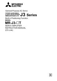
B a l l S c re w D r i v e n L i n e a r A c t u a t o rs For applications requiring positioning repeatability of 0.02 mm Speedsofupto1.2m/sarepossible Axial loads up to 1,600 N are allowable563174<strong>DGE</strong> linear actuatorsencapsulate their mechanicaldrives within the body ofthe actuator. This protectsthem from contamination andprevents premature failure.3.0321 Ball screw2 Drive shaft / trunnion3 Coupling housing4 Aluminum profile5 Drive6 Slide7 Sensors can be integratedWide range of optionsfor third-party motormounting kitsMulti-axis systems for sizes18 to 63 mm. Cantilever-typehandling gantries, lineargantries, planar surfacegantries and X/Y axis tablescan easily be made.03/2006 – Subject to change – Info 130 USFesto Corporation81
Ball Screw Driven <strong>Linear</strong> <strong>Actuators</strong>Product OverviewTechnology Section 3<strong>Actuators</strong> Without Guide <strong>DGE</strong>-SP Section 3.1 Page 83These actuators are ideal for moving light loads(up to 163 kg). They can also be combined with externallinear guides, to move heavy loads, or to withstandhigh moment loads. Sizes: 18, 25, 40, 63 Stroke lengths: 100 … 2,000 mm Max Speed: 1.2 m/s Repeatability: ±0.02 mm<strong>Actuators</strong> With Recirculating Ball Bearing Guide <strong>DGE</strong>-SP-KF Section 3.2 Page 95These actuators are used to carry a maximum load ormoment in a compact space. Loads up to 1,433 kg arepossible, as are moments up to 1,820 Nm in pitch and yawand up to 580 Nm in the roll direction. Sizes: 18, 25, 40, 63 Stroke lengths: 100 … 2,000 mm Max Speed: 1.2 m/s Repeatability: ±0.02 mm Extended slide available for increased load capacityDust Proof VersionGuide and slide are fitted with a cover to protect againstthe ingress of particles from above and the side.<strong>DGE</strong>-SP-KF-GA Sizes: 25, 40 Stroke lengths: 140 … 1,440 mm Max Speed: 1 m/s Repeatability: ±0.02 mm33.0<strong>Actuators</strong> With Heavy-duty Guide (Dual Ball Bearing Guide) <strong>DGE</strong>-SP-HD Section 3.3 Page 115Used in applications where you need the lowest profilepossible to withstand high moment loads. Pitch and yawmoment loads up to 560 Nm are possible, as are rollmoment loads up to 375 Nm. Sizes: 18, 25, 40 Stroke lengths: 100 … 1,500 mm Max Speed: 1 m/s Repeatability: ±0.02 mm Highest roll moment capacity82 Festo CorporationInfo 130 US – Subject to change – 03/2006
D G E - SP B a l l S c re w D r i v e n L i n e a r A c t u a t o rs33.1Stroke lengths from100 to 2,000 mmActuator without integralguide, for use with externallinear guidePrecision with flexibilityWide range of optionsfor third-party motormounting kitsComprehensive range ofmounting accessoriesfor multi-axis combinations03/2006 – Subject to change – Info 130 USFesto Corporation83
Technical Data<strong>DGE</strong>-SP Ball Screw Driven <strong>Linear</strong> <strong>Actuators</strong>Sizes: 18, 25, 40, 63Stroke length: 100 … 2,000 mmGeneral Technical DataSize 18 25 40 63DesignElectromechanical actuator with ball screw driveGuide –Mounting positionAnyWorking stroke 1) [mm] 100 … 500 100 … 1,000 200 … 1,500 300 … 2,000Max. applied load 2) [kg] 6 25 50 150Max. axial force F x [N] 140 250 600 1,600Max. input torque [Nm] 0.1 0.45 2.1 8.5Max. no-load running torque 3) [Nm] 0.05 0.15 0.5 1.4Max. speed 4) [m/s] 0.2 0.5 1 1.2Repeatability [mm] ±0.0231) Total stroke = working stroke + 2x stroke reserve (see page 85)2) This figure is at maximum speed and acceleration.3) Measured at a speed of 0.2 m/s4) The maximum speed is dependent on the stroke length (see graphs on page 87).Operating and Environmental ConditionsSize 18 25 40 633.1Ambient temperature [°C] 0…+60Protection classIP40Weights [kg]Size 18 25 40 63Basic weight with 0 mm stroke 1) 0.55 1.4 4.3 12.5Additional weight per 100 mm stroke 0.21 0.41 0.71 2.531) <strong>Inc</strong>luding coupling housingMass Moment of InertiaSize 18 25 40 63J O [kg cm 2 ] 0.007 0.029 0.364 3.15J H per meter stroke [kg cm 2 /m] 0.031 0.121 1 6.67J L per kg applied load [kg cm 2 /kg] 0.005 0.025 0.101 0.228The total mass moment of inertia J A is calculated as follows: J A =J O +J H xworkingstroke[m]+J L xm applied load [kg]84 Festo CorporationInfo 130 US – Subject to change – 03/2006
Technical Data<strong>DGE</strong>-SP Ball Screw Driven <strong>Linear</strong> <strong>Actuators</strong>Ball ScrewSize 18 25 40 63Diameter [mm] 8 12 20 32Lead [mm/rev.] 4 10 20 30MaterialsSectional View1 2 3 4 5Actuator1 End cap Anodized aluminum2 Ball Screw Rolled steel3 Drive Anodized aluminum4 Profile Anodized aluminum5 Cover strip Corrosion resistant steelStroke ReserveL12 The stroke reserve is arecommended safety distanceavailable on both sides ofthe actuator in addition tothe stroke.L11 Internal mechanical stop1 Working stroke33.1Example:Type <strong>DGE</strong>-25-500-SPWorking stroke = 500 mmStroke reserve = (2x 10 mm)=20mmTotal stroke = 500 mm +20 mm= 520 mmSize 18 25 40 63L12 per end position [mm] 6.5 10 20 3003/2006 – Subject to change – Info 130 USFesto Corporation85
Technical Data – Load Values<strong>DGE</strong>-SP Ball Screw Driven <strong>Linear</strong> <strong>Actuators</strong>Characteristic Load ValuesThe indicated forces and torquesrefer to the center line of the internaldiameter of the profile. They mustnot be exceeded in the dynamicrange.If the actuator is subjected tomore than two of the indicatedforces and torques simultaneously,the following equations must besatisfied in addition to the indicatedmaximum loads:Fz+My +Mz ≤ 1Fz max. My max. Mz max.MxMx max.≤ 133.1Permissible Forces and TorquesSize 18 25 40 63Fy max. [N] – – – –Fz max. [N] 1.8 2 15 106Mx max. [Nm] 0.5 1 4 8My max. [Nm] 0.8 1.5 4 18Mz max. [Nm] 0.8 1.5 4 18Second Moment of AreaLyLxSize 18 25 40 63Lx [mm 4 ] 72.3 x 10 3 240 x 10 3 748 x 10 3 6031 x 10 3Ly [mm 4 ] 69.8 x 10 3 224 x 10 3 673 x 10 3 5688 x 10 3– Design tool– PtToolSelection and calculation softwarewww.festo.com/en/engineering86 Festo CorporationInfo 130 US – Subject to change – 03/2006
Technical Data – Maximum Speed and Ball Screw Life<strong>DGE</strong>-SP Ball Screw Driven <strong>Linear</strong> <strong>Actuators</strong>Maximum Permissible Speed “v” or Drive rpm “n” as a Function of Stroke “l”<strong>DGE</strong>-18<strong>DGE</strong>-25v[m/s]n[rpm]v[m/s]n[rpm]l [mm]l [mm]<strong>DGE</strong>-40<strong>DGE</strong>-63v[m/s]n[rpm]v[m/s]n[rpm]l [mm]l [mm]3Ball Screw Life vs. Axial Force “F x ”This graph is based on theoreticalvalues. Actual values are applicationdependent, and changes in direction,speed, acceleration, deceleration,external forces, and environmentalconditions (dirt, temperature, etc.)will produce different results.3.116801000Force [N]10010<strong>DGE</strong>-63<strong>DGE</strong>-40<strong>DGE</strong>-25<strong>DGE</strong>-1811x10 4 1x10 5 1x10 6 1x10 7 1x10 8 1x10 9 1x10 10 1x10 11 1x10 12Travel Life [km]03/2006 – Subject to change – Info 130 US Festo Corporation87
Technical Data – Maximum Support Span<strong>DGE</strong>-SP Ball Screw Driven <strong>Linear</strong> <strong>Actuators</strong>Maximum Permissible Support Span “l” as a Function of Force “F”The actuator may need to besupported with central supports inorder to restrict deflection with longstroke lengths. The followingdiagrams serve to determine themaximum permissible support span las a function of force F acting uponthe actuator.1 Force on the surface of the driveF zF zF z2 Force on the front of the driveF y F y F yMaximum Permissible Support Span “l” (without central support) as a Function of Force “F“<strong>DGE</strong>-18<strong>DGE</strong>-253F[N]F[N]3.1l [mm]l [mm]<strong>DGE</strong>-40<strong>DGE</strong>-63F[N]F[N]l [mm]l [mm]1288 Festo CorporationInfo 130 US – Subject to change – 03/2006
Technical Data – Dimensions<strong>DGE</strong>-SP Ball Screw Driven <strong>Linear</strong> <strong>Actuators</strong>DimensionsSize 18stroke length1 Coupling housing3 Centering hole forfoot mounting HP4 Coupling8 Drive in end position ofthe working stroke9 Stroke reserve, see page 85for detailsaJ Internal mechanical stop3ProfileSize 182 Sensor slot forproximity sensor3.103/2006 – Subject to change – Info 130 USFesto Corporation89
Technical Data – Dimensions<strong>DGE</strong>-SP Ball Screw Driven <strong>Linear</strong> <strong>Actuators</strong>DimensionsSize 25 … 63stroke length33.11 Coupling housing3 Centering hole forfoot mounting HP4 Coupling8 Drive in end position of theworking stroke.ProfileSize 25 Size 40 Size 639 Stroke reserve, see page 85for detailsaJ Internal mechanical stop2 Sensor slot forproximity sensor6 Mounting slot for slot nut NSTSize B1 B3 B4 B5 B6 B11 B12 B13 B14 D1 D2 D3 D4 D5 D6 D7 D8 D9 H1 H2 H3∅ ∅ ∅ ∅ ∅ ∅[mm] +0.2 h6 +0.2 g7 g725 45 19 39.1 18 32.5 18.5 11 38 4 6 3.3 5.2 M5 32 M4 M4 32 44 63 57 52.840 64 21 53 28 49 22.5 12 38 5 12 4.4 6.5 M5 48 M5 M4 32 44 86 78 71.863 106 24 89 44 83 47.5 25 56 7 20 6.4 8.5 M8 72 M8 M6 48 64 131 122 115Size H4 H5 H9 J2 L1 L2 L3 L6 L7 L8 L9 L11 L12 L13 L14 L15 L16 1) T1 T2 T3[mm] ±0.1 ±0.1 ±0.125 19.6 26.5 19 4 213 101.5 25 109 30 – 50 6 10 43 2.5 14 3 13 2 7.540 26.5 37 19 5 315 153 31 171 70 130 40 7 20 46 3 14.5 3.5 13 3 10.563 44.5 61 28 8 410 200 63 234 110 190 70 9 30 83 4 23 –2 21 4 12.51) Negative dimension: Protrudes beyond coupling housing90 Festo CorporationInfo 130 US – Subject to change – 03/2006
Overview and Ordering Data<strong>DGE</strong>-SP Ball Screw Driven <strong>Linear</strong> <strong>Actuators</strong>Order CodeMandatory DataNote Note:The insertion point for the proximitysensor is located on the right-handside of the actuator <strong>DGE</strong>-…-SP.O=topU=underneathV=frontH=rearR=rightL=leftOrder CodeOptionsKG = Coupling housingAdapter for mounting the motor on the actuatorCouplingConnecting element between actuator and motor(For third- party motor mounting kits, see page 196.)FlangeConnecting element between coupling housing and motor(For third-party motor mounting kits, see page 196.)3B = Mounting slot cover / S = Sensor slot coverFor protection against the ingress of dirt3.1G/H/I/J/N =ProximitysensorsFor use as a proximity signal and for safety monitoringV = Plug socket with cableFor proximity sensorsY = Slot nutFor mounting attachmentsM =CentralsupportFor mounting the actuatorF = Foot mounting kitFor mounting the actuator03/2006 – Subject to change – Info 130 USFesto Corporation91
Ordering Data<strong>DGE</strong>-SP Ball Screw Driven <strong>Linear</strong> <strong>Actuators</strong>MMandatory DataOOptionsModule No. Design Size Stroke Drive function Coupling housing193745193746193747193748<strong>DGE</strong> 182540631 … 2,000 SP KGLGOrderingExample193747 <strong>DGE</strong> – 40 – 800 – SP – LG –3Ordering TableSize 18 25 40 63 Code For info,see pageM Module No. 193745 193746 193747 193748 –Design Electromechanical linear actuator <strong>DGE</strong> <strong>DGE</strong>Size 18 25 40 63 -…Working stroke [mm] 100, 200, 300,400, 500100, 200, 300,400, 500, 600,700, 800, 900,1,000200, 300, 400,500, 600, 800,1,000, 1,200,1,400, 1,500300, 400, 500,600, 800,1,000, 1,200,1,400, 1,500,1,800, 2,000– 1 … 1,000 1 … 1,500 1 … 2,000Drive function Electromechanical drive with ball screw -SP -SPO Coupling housing Coupling housing -KG 91Attached,-LG– ––large design-…84Entercode3.192 Festo CorporationInfo 130 US – Subject to change – 03/2006
Ordering Data<strong>DGE</strong>-SP Ball Screw Driven <strong>Linear</strong> <strong>Actuators</strong>OOptionsAccessories Slot cover Slot nut Central support Foot mounting Proximity sensor Plug socketZUB…S…B…Y …M …F …G…H…I…J…N…VZUB – 2S2B–10Y– –F–2G–Ordering TableSize 18 25 40 63 Conditions Code For info,see page Accessories Supplied separately ZUB- 199 ZUB-O Slot cover Sensor slot 1…10 …SMounting slot – – 1…10 …B205Slot nut for mounting slot 1…10 …Y 205Central support 1…10 …M 202Foot mounting (kit) 1…10 …F 202Proximity sensor with cable, 2.5 m 1…10 …Gwith plug 1…10 …Hcontactless withcable, 2.5 m1…10 …I91,210contactless, plug 1…10 …JNC contact with 1…10 …Ncable, 2.5 mPlug socket with cable, 2.5 m 1…10 1 …V 2101 For use with proximity sensors H and J.Entercode33.103/2006 – Subject to change – Info 130 USFesto Corporation93
94 Festo Corporation Info 130 US – Subject to change – 03/2006
<strong>DGE</strong>-SP-KF Ball Screw Driven <strong>Linear</strong> <strong>Actuators</strong> with Recirculating Ball Bearing GuideGA: Dust Proof VersionStroke lengths from100 to 2,000 mm3Standard or extended slideGuides on these <strong>DGE</strong>s areup to three times wider thanstandard width guides,providing superior loadand moment capacity3.2Use when medium to highloads need to be movedDust proof version<strong>DGE</strong>-SP-KF-GAWide range of optionsfor third-party motormounting kitsComprehensive range ofmounting accessoriesfor multi-axis combinationsGK: Standard Slide03/2006 – Subject to change – Info 130 USFesto Corporation95
Technical Data<strong>DGE</strong>-SP-KF Ball Screw Driven <strong>Linear</strong> <strong>Actuators</strong> with Recirculating Ball Bearing GuideSizes: 18, 25, 40, 63Stroke length: 100 … 2,000 mmGKGAGeneral Technical DataSize 18 25 40 63DesignElectromechanical actuator with ball screw and recirculating ball bearing guideGuideRecirculating ball bearing guideMounting positionAnyWorking stroke 1) Standard Version - GK [mm] 100 … 500 100 … 1,000 200 … 1,500 300 … 2,000Extended Slide - GV [mm] 110 … 410 170 … 870 170 … 1,270 150 … 1,650Dust Proof Version - GA [mm] – 170 … 970 140 … 1,440 –Max. applied load 2) [kg] 6 25 50 150Max. axial force F x [N] 140 250 600 1,600Max. input torque [Nm] 0.1 0.45 2.1 8.5Max. no-load running torque 3) [Nm] 0.05 0.15 0.5 1.4Max. speed 4) [m/s] 0.2 0.5 1 1.2Repeatability [mm] ±0.0231) Total stroke = working stroke + 2x stroke reserve (see page 101)2) This figure is at maximum speed and acceleration.3) Measured at a speed of 0.2m/s4) The maximum speed is dependent on the stroke length (see graphs on page 102).3.2Operating and Environmental ConditionsSize 18 25 40 63Ambient temperature [°C] 0…+60Protection classIP40Weights [kg]Size 18 25 40 63Basic weight with 0 mm stroke 1) Standard Version - GK 1 2.1 6.4 18.1Extended Slide - GV 1.52 3.26 10.04 32.2Dust Proof Version - GA – 3.1 8.97 –Additional weight per 100 mm Standard Version - GK 0.3 0.56 1.14 3.31stroke Extended Slide - GV 0.3 0.56 1.14 3.31Dust Proof Version - GA – 0.65 1.26 –Additional slide KL/KR 0.25 0.38 1.06 3.11) <strong>Inc</strong>luding coupling housing and slide96 Festo CorporationInfo 130 US – Subject to change – 03/2006
Technical Data<strong>DGE</strong>-SP-KF Ball Screw Driven <strong>Linear</strong> <strong>Actuators</strong> with Recirculating Ball Bearing GuideMass Moment of InertiaSize 18 25 40 63J O GK [kg cm 2 ] 0.008 0.04 0.48 3.88GV [kg cm 2 ] 0.0117 0.0617 0.782 6.77GA [kg cm 2 ] – 0.0573 0.678 –J H per meter stroke [kg cm 2 /m] 0.031 0.121 1 6.67J L per kg applied load [kg cm 2 /kg] 0.005 0.025 0.101 0.228J W for additional slide [kg cm 2 ] 0.001 0.0096 0.107 0.707The total mass moment of inertia J A is calculated as follows: J A =J O +J H xworkingstroke[m]+J L xm applied load [kg]Ball ScrewSize 18 25 40 63Diameter [mm] 8 12 20 32Lead [mm/rev.] 4 10 20 30MaterialsSectional View1 2 3 4 53Actuator3.21 End cap Anodized aluminum2 Ball Screw Rolled steel3 Slide Anodized aluminum4 Profile Anodized aluminum5 Cover strip Corrosion resistant steel03/2006 – Subject to change – Info 130 USFesto Corporation97
Technical Data – Load Values<strong>DGE</strong>-SP-KF Ball Screw Driven <strong>Linear</strong> <strong>Actuators</strong> with Recirculating Ball Bearing GuideCharacteristic Load Values for <strong>Actuators</strong> with Standard Slide GK or Dust Proof Version GAThe indicated forces and torquesrefer to the center of the guide rail.They must not be exceeded in thedynamic range.If the actuator is subjected tomore than two of the indicatedforces and torques simultaneously,the following equations must besatisfied in addition to the indicatedmaximum loads:Fy+Fz +Mx +My +Mz ≤ 1Fy max. Fz max. Mx max. My max. Mz max.3Permissible Forces and Torques GK/GASize 18 25 40 63Fy max. [N] 930 3,080 7,300 14,050Fz max. [N] 930 3,080 7,300 14,050Mx max. [Nm] 7 45 170 580My max. [Nm] 23 85 330 910Mz max. [Nm] 23 85 330 9103.2Second Moment of AreaLyLxSize 18 25 40 63Lx [mm 4 ] 172.3 x 10 3 551 x 10 3 1908 x 10 3 13677 x 10 3Ly [mm 4 ] 73.7 x 10 3 250 x 10 3 875 x 10 3 6987 x 10 3– Design tool– PtToolSelection and calculation softwarewww.festo.com/en/engineering98 Festo CorporationInfo 130 US – Subject to change – 03/2006
Technical Data – Load Values<strong>DGE</strong>-SP-KF Ball Screw Driven <strong>Linear</strong> <strong>Actuators</strong> with Recirculating Ball Bearing GuideCharacteristic Load Values for Actuator with Extended Slide GVThe indicated forces and torquesrefer to the center of the guide rail.They must not be exceeded in thedynamic range.If the drive is subjected to morethan two of the indicated forcesand torques simultaneously, thefollowing equations must besatisfied in addition to the indicatedmaximum loads:Fy+Fz +Mx +My +Mz ≤ 1Fy max. Fz max. Mx max. My max. Mz max.Permissible Forces and TorquesSize 18 25 40 63Fy max. [N] 930 3,080 7,300 14,050Fz max. [N] 930 3,080 7,300 14,050Ly [mm 73.7 250 x 875 x 6987 xMx max. [Nm] 7 45 170 5803My max. [Nm] 45 170 660 1,820Mz max. [Nm] 45 170 660 1,8203.2Second Moment of AreaLyLxSize 18 25 40 63Lx [mm 4 ] 172.3 x 10 3 551 x 10 3 1908 x 10 3 13677 x 10 303/2006 – Subject to change – Info 130 USFesto Corporation99
Technical Data – Bearing Guide Life vs. Applied Load<strong>DGE</strong>-SP-KF Ball Screw Driven <strong>Linear</strong> <strong>Actuators</strong> with Recirculating Ball Bearing GuideBearing Guide Life vs. Applied LoadNote: These graphs are based ontheoretical values, assuming thatthe load is centered directly abovethe carriage. Actual values areapplication dependent, and changesin direction, speed, acceleration,deceleration, external forces, andenvironmental conditions (dirt,temperature, etc.) will producedifferent results.<strong>DGE</strong>-18900800700600<strong>DGE</strong>-25300025002000Load [N]500400300Load [N]1500100020010050001x10 3 1x10 4 1x10 5 1x10 6 1x10 7Travel Life [km]01x10 21x10 31x104 1x10 5 1x10 6 1x10 7Travel Life [km]3<strong>DGE</strong>-40700060005000<strong>DGE</strong>-631400012000100003.2Load [N]40003000Load [N]80006000200040001000200001x10 21x10 31x1041x10 5 1x10 6 1x10 701x10 21x10 31x1041x10 5 1x10 6 1x10 7Travel Life [km]Travel Life [km]100 Festo CorporationInfo 130 US – Subject to change – 03/2006
Technical Data – Stroke Length<strong>DGE</strong>-SP-KF Ball Screw Driven <strong>Linear</strong> <strong>Actuators</strong> with Recirculating Ball Bearing GuideStroke ReserveL12 The stroke reserve is arecommended safety distanceavailable on both sides of theactuator in addition to thestroke.L17 Slide lengthL11 Internal mechanical stop1 Working strokeExample:Type <strong>DGE</strong>-25-500-SPWorking stroke = 500 mmStroke reserve =(2x 10 mm)=20mmTotal stroke = 500 mm +20 mm= 520 mmSize 18 25 40 63L12 per end position [mm] 6.5 10 20 30Working Stroke Reduction with Standard Slide GK or Extended Slide GV and Additional Slide KL/KRL17 = Slide/additionalslide lengthL18 = Distance betweenboth slides4 Additional slideForaballscrewactuatorwithadditional slide, the working strokeis reduced by the length of theadditional slide and the distancebetween both slides.Example:Type <strong>DGE</strong>-25-500-SP-…-KF-GK-KLWorking stroke withoutadditional slide = 500 mmL18 = 20 mmL17= 105 mmWorking stroke withadditional slide = 375 mm(500 mm – 20 mm – 105 mm)33.2Working Stroke reduction with Standard Slide GK with Optional Emergency Buffer2 Working stroke reduction3 Emergency buffer4 Shock absorber retainerL12 Stroke reserveFor a ball screw actuator withoptional emergency buffer, theworking stroke is reduced, as thestroke reserve is smaller thanthe overall dimensions of theemergency buffer and shockabsorber retainer. The workingstroke reduction varies dependingonthesizeoftheactuator.Size 18 25 40 63Working stroke reduction [mm] 10 30 60 10003/2006 – Subject to change – Info 130 USFesto Corporation101
Technical Data – Maximum Speed and Ball Screw Life<strong>DGE</strong>-SP-KF Ball Screw Driven <strong>Linear</strong> <strong>Actuators</strong> with Recirculating Ball Bearing GuideMaximum Permissible Speed “v” or Drive rpm “n” as a Function of Stroke “l”<strong>DGE</strong>-18<strong>DGE</strong>-25v[m/s]n[rpm]v[m/s]n[rpm]l [mm]l [mm]<strong>DGE</strong>-40<strong>DGE</strong>-63v[m/s]n[rpm]v[m/s]n[rpm]33.2Ball Screw Life vs. Axial Force “F x ”This graph is based on theoreticalvalues. Actual values are applicationdependent, and changes in direction,speed, acceleration, deceleration,l [mm]external forces, and environmentalconditions (dirt, temperature, etc.)will produce different results.l [mm]16801000Force [N]10010<strong>DGE</strong>-63<strong>DGE</strong>-40<strong>DGE</strong>-25<strong>DGE</strong>-1811x10 4 1x10 5 1x10 6 1x10 7 1x10 8 1x10 9 1x10 10 1x10 11 1x10 12Travel Life [km]102 Festo CorporationInfo 130 US – Subject to change – 03/2006
Technical Data – Maximum Support Span<strong>DGE</strong>-SP-KF Ball Screw Driven <strong>Linear</strong> <strong>Actuators</strong> with Recirculating Ball Bearing GuideMaximum Permissible Support Span “l” as a Function of Force “F”The actuator may need to besupportedwithcentralsupportsin order to restrict deflectionwith long stroke lengths.The following diagrams serve todetermine the maximum permissiblesu p p o r t sp a n l a s a f u n c t i o n o ffor ce F acti n g u pon the actu ator.1 Force on the surface of the slideF zF zF z2 Force on the front of the slideF y F y F yMaximum Permissible Support Span “l” (without central support) as a Function of Force “F”<strong>DGE</strong>-18<strong>DGE</strong>-25F[N]F[N]33.2l [mm]l [mm]<strong>DGE</strong>-40<strong>DGE</strong>-63F[N]F[N]l [mm]l [mm]1203/2006 – Subject to change – Info 130 USFesto Corporation103
Technical Data – Dimensions<strong>DGE</strong>-SP-KF Ball Screw Driven <strong>Linear</strong> <strong>Actuators</strong> with Recirculating Ball Bearing GuideDimensionsStandard Slide GKSize 18stroke length5 Hole for centering pin ZBS-5Basic dimensions Seepage89Additional Slide KL/KRSize 18stroke length5 Hole for centering pin ZBS-56 Additional slide<strong>DGE</strong>-18-…-KL/KR3Extended Slide GVSize 18stroke length2 Shock absorber retainer KYP3 Emergency buffer NPE5 Hole for centering pin ZBS-53.2ProfileSize 182 Sensor slot forproximity sensor104 Festo CorporationInfo 130 US – Subject to change – 03/2006
Technical Data – Dimensions<strong>DGE</strong>-SP-KF Ball Screw Driven <strong>Linear</strong> <strong>Actuators</strong> with Recirculating Ball Bearing GuideDimensionsStandard Slide GKSize 25 … 63stroke length5 Hole for centering sleeve ZBH-96 Mounting slot for slot nut NSTL7 Hole for central mounting SLZZBasic dimensions Seepage90Size 40/635 Hole for centering sleeve ZBH-96 Mounting slot for slot nut NSTL3Size 25 … 634 Additional slide<strong>DGE</strong>-…-…-KL/KR5 Hole for centering sleeve ZBH-96 Mounting slot for slot nut NSTL3.2Size B7 B8 B9 B10 B15 D10 D11 H7 H10[mm] ±0.2 ∅ G725 48 67 32 – 23.5 M5 14 68.5 18.540 78.5 96.5 55 20 42 M5 25 90.5 2063 121 142 90 40 71 M8 25 144.5 30Size H11 L1 L2 L17 L18 1) L19 L20 T4 T8[mm] ±0.1 ±0.1 max.25 8.2 213 101.5 105 20 88 – 12.5 8.540 7 315 153 167 20 150 58 12.5 8.563 12.5 410 200 230 27 200 72 20.5 10.51) Recommended minimum distance for access to lubrication nipple.03/2006 – Subject to change – Info 130 USFesto Corporation105
Technical Data – Dimensions<strong>DGE</strong>-SP-KF Ball Screw Driven <strong>Linear</strong> <strong>Actuators</strong> with Recirculating Ball Bearing GuideDimensionsStandard Slide GK – ProfileSize 25 Size 40 Size 632 Sensor slot for proximitysensor6 Mounting slot for slot nut NST33.2106 Festo CorporationInfo 130 US – Subject to change – 03/2006
Technical Data – Dimensions<strong>DGE</strong>-SP-KF Ball Screw Driven <strong>Linear</strong> <strong>Actuators</strong> with Recirculating Ball Bearing GuideDimensionsExtended Slide GVSize 25 … 63stroke length3 Emergency buffer NPE4 Shock absorber retainer KYP5 Hole for centering sleeve ZBH-96 Slot for slot nut NSTL7 Hole for central mounting SLZZ Basic dimensions Seepage90Size 255 Hole for centering sleeve ZBH-96 Mounting slot for slot nut NSTLSize 40/635 Hole for centering sleeve ZBH-96 Mounting slot for slot nut NSTL33.2Size B7 B8 B9 B10 B15 D10 D11 H7 H10 H11[mm] ±0.2 ∅ G725 48 67 32 – 23.5 M5 14 68.5 18.5 8.240 78.5 96.5 55 20 42 M5 25 90.5 20 763 121 142 90 40 71 M8 25 144.5 30 12.5Size L1 L2 L15 L16 L17 L19 L20 L21 T4 T8[mm] ±0.2 ±0.1 ±0.1 ±0.1 max.25 343 171.5 25 19 205 88 – – 12.5 8.540 545 271.5 40 32 337 150 58 40 12.5 8.563 760 380 60 44 480 200 72 120 20.5 10.503/2006 – Subject to change – Info 130 USFesto Corporation107
Technical Data – Dimensions<strong>DGE</strong>-SP-KF Ball Screw Driven <strong>Linear</strong> <strong>Actuators</strong> with Recirculating Ball Bearing GuideDimensionsDust Proof Version GASize 25stroke length33.2108 Festo CorporationInfo 130 US – Subject to change – 03/2006
Technical Data – Dimensions<strong>DGE</strong>-SP-KF Ball Screw Driven <strong>Linear</strong> <strong>Actuators</strong> with Recirculating Ball Bearing GuideDimensionsDust Proof Version GASize 40stroke length33.203/2006 – Subject to change – Info 130 USFesto Corporation109
Overview and Ordering Data<strong>DGE</strong>-SP-KF Ball Screw Driven <strong>Linear</strong> <strong>Actuators</strong> with Recirculating Ball Bearing GuideOrder CodeMandatory DataStandard Slide GKExtended Slide GVNote: See belowNote: See below33.2KF = Recirculating ball bearing guideKL = Additional slide at leftKR = Additional slide at rightSV = Slide at frontSH = Slide at rearNote:The insertion point for theproximity sensor is located onthe right-hand side of the actuator<strong>DGE</strong>- ...- SP- K F.U=underneathO=topR=rightL=leftV=frontH=rearDust Proof Version GA110 Festo CorporationInfo 130 US – Subject to change – 03/2006
Overview and Ordering Data<strong>DGE</strong>-SP-KF Ball Screw Driven <strong>Linear</strong> <strong>Actuators</strong> with Recirculating Ball Bearing GuideOrder CodeOptionsA = Emergency buffer with retainer, for avoiding damageat the end stop in the event of malfunctionC/E = Shock absorber kit, for avoiding damageat the end stop in the event of malfunctionL = Switching lug, for sensing the slide positionT = Sensor bracket, adapter for mounting theinductive proximity sensors on the actuatorO/P/W/R = Inductive proximity sensorFor use as a signal generator and for safety monitoringX = Slot nut for slide, for mounting loads and attachments on the slideZ = Centering pins/sleeves, for centering loads and attachments on the slideKG = Coupling housingAdapter for mounting the motor on the actuatorKSE =CouplingConnecting element between actuator and motor(For third-party motor mounting kits, see page 196.)3MTR-FL =FlangeConnecting element between coupling housing and motor(For third-party motor mounting kits, see page 196.)3.2B/S = Slot cover, for protection against the ingress of dirtG/H/I/J/N = Proximity sensors, For use as a signal or safety checkV = Plug socket with cable, for proximity sensorsY = Slot Nut, for mounting attachmentsM = Central support, for mounting the actuatorF = Foot mounting kitFor mounting the actuator03/2006 – Subject to change – Info 130 USFesto Corporation111
Ordering Data<strong>DGE</strong>-SP-KF Ball Screw Driven <strong>Linear</strong> <strong>Actuators</strong> with Recirculating Ball Bearing GuideMMandatory DataOOptionsModule No. Design Size Stroke Drive function CouplinghousingGuideSlide193745193746193747193748<strong>DGE</strong> 182540631 … 1,650 SP KGLGKFGKGVGAOrderingExample193745 <strong>DGE</strong> – 18 – 400 – SP – KG – KF – GVOrdering TableSize 18 25 40 63 Conditions Code For info,see pageEntercodeM Module No. 193745 193746 193747 193748 –33.2Design Electromechanical linear actuator <strong>DGE</strong> 96 <strong>DGE</strong>Size 18 25 40 63 -… 96Working Standard slide GK 100, 200, 300,stroke [mm]400, 500Extended slide GV 110, 210, 310,410Dust proof version GA100, 200, 300,400, 500, 600,700, 800, 900,1,000200, 300, 400,500, 600, 800,1,000, 1,200,1,400, 1,500300, 400, 500,600, 800,1,000, 1,200,1,400, 1,500,1,800, 2,000– 1 … 1000 1 … 1500 1 … 2000170, 270, 370,470, 570, 670,770, 870170, 270, 370,570, 770, 970,1,170, 1,270150, 250, 450,650, 850,1,050, 1,150,1,450, 1,650– 1 … 870 1 … 1,270 1 … 1,650–170, 270, 370,470, 570, 670,770, 870, 970140, 240, 340,440, 540, 740,940, 1,140,1,340, 1,440– 1 … 970 1 … 1,440 –Drive function Electromechanical drive with ball screw -SP 97 -SPO Coupling housing Coupling housing -KGAttached, large-LG 111– ––designGuide Recirculating ball bearing guide 1 -KF 96 -KFSlide Standard Standard 2 -GKExtended Extended 2 -GV 104 Dust proof – Dust proof version – 2 -GA–-…-…-…9696961 Only with slide GK, GV, GA.2 Only with slide attachment position SV, SH.112 Festo CorporationInfo 130 US – Subject to change – 03/2006
Ordering Data<strong>DGE</strong>-SP-KF Ball Screw Driven <strong>Linear</strong> <strong>Actuators</strong> with Recirculating Ball Bearing GuideOOptionsSlide attachment positionAdditional slideSVSHKLKR– SV – –Ordering TableSize 18 25 40 63 Conditions Code For info ,see pageEntercode Slide attachment position Slide at front -SV109OSlide at rear-SHAdditional left Standard slide at left 3 -KLslide (effective stroke reduction) (85 mm) (105 mm) (167 mm) (230 mm)109right Standard slide at right 3 -KR(effective stroke reduction) (85 mm) (105 mm) (167 mm) (230 mm)3 Not available with slide GA. 33.203/2006 – Subject to change – Info 130 USFesto Corporation113
Ordering Data<strong>DGE</strong>-SP-KF Ball Screw Driven <strong>Linear</strong> <strong>Actuators</strong> with Recirculating Ball Bearing GuideOOptionsAcc.SlotcoverSlotnutCentralsupportFootmountingEmergencybuffer andretainerShockabsorberCenteringpins/sleevesProximitysensorPlugsocketSensorbracketSwitchinglugInductivesensorZUB…S…B…Y…X…M …F …A …C…E…Z…G…H…I…J…N…V …T L …O…P…W…RZUB – 2S–10Y– –F– – – –2G– – – –33.2Ordering TableSize 18 25 40 63 Conditions Code For info,see page Accessories Supplied separately ZUB- 199 ZUB-O Slot cover Sensor slot 1…10 …SMounting slot – – 1…10 …B205Slot nut for mounting slot 1…10 …Yfor slide – 1…10 …X205Central support 1…10 …M 201Foot mounting (kit) 1…10 …F 202Emergency buffer 1…2 4 …Aand retainer for (effective stroke reductionwith emergency(10 mm) (30 mm) (60 mm) (100 mm)KF204buffer at both ends)Shock absorber and retainer for KF- 1…2 5 …CGK, KF-GV203for KF-GA – 1…2 – 6 …ECentring pins/sleeves (pack of 10) 10, 20, 30, 40, 50, 60, 70, 80, 90 …Z 205Proximity sensor with cable, 2.5 m 1…10 …G(For actuator with plug 1…10 …Hprofile slot) contactless with 1…10 …Icable, 2.5 m110, 210contactless, plug 1…10 …JNC contact with 1…10 …Ncable, 2.5 mPlug socket with cable, 2.5 m 1…10 7 …V 210Sensor bracket for inductive sensors 1…5 5 …T 208Switching lug 1 5 L 208Inductive sensor NO contact, cable 1…5 5 …ONC contact, cable 1…5 5 …PNO contact, plug 1…5 5 …W110, 210NC contact, plug 1…5 5 …REntercode4 Only with slide GK.5 Not available with slide GA.6 Only with slide GA.7 For use with proximity sensors H, J, W and R.114 Festo CorporationInfo 130 US – Subject to change – 03/2006
D GE-SP -HD B all Screw D ri ven L i near Act u ators wi t h Heavy-du t y Gu i de33.3Stroke lengths from100 to 1,500 mmHigh guide precisionand sturdy constructionfor moving heavy loadsWide range of optionsfor third-party motormounting kitsComprehensive range ofmounting accessoriesfor multi-axis combinations03/2006 – Subject to change – Info 130 USFesto Corporation115
Technical Data<strong>DGE</strong>-SP-HD Ball Screw Driven <strong>Linear</strong> <strong>Actuators</strong> with Heavy-duty GuideSizes: 18, 25, 40Stroke lengths: 100 … 1,500 mmGeneral Technical DataSize 18-HD18 25-HD25 25-HD40 40-HD40DesignElectromechanical actuator with heavy-duty guideGuideRecirculating ball bearing guideMounting positionAnyWorking stroke [mm] 100 … 400 100 … 900 100 … 900 200 … 1,500Max. applied load 1) [kg] 6 25 25 50Max. axial force F x [N] 140 250 250 600Max. input torque [Nm] 0.1 0.45 0.45 2.1No-load running torque 2) [Nm] 0.05 0.2 0.2 0.6Max. speed 3) [m/s] 0.2 0.5 0.5 1Repeatability [mm] ±0.0233.31) This figure is at maximum speed and acceleration.2) Measured at a speed of 0.2 m/s3) The maximum speed is dependent on the stroke length (see graphs on page 119).Operating and Environmental ConditionsSize 18-HD18 25-HD25 25-HD40 40-HD40Ambient temperature [°C] 0…+60Protection classIP40Weights [kg]Size 18-HD18 25-HD25 25-HD40 40-HD40Basic weight with 0 mm stroke 1) 4.31 7.04 16.13 19.02Additional weight per 100 mm stroke 0.32 1.6 2.19 2.621) <strong>Inc</strong>luding coupling housing and slideMass Moment of InertiaSize 18-HD18 25-HD25 25-HD40 40-HD40J O [kg cm 2 ] 0.013 0.086 0.375 0.698J H per meter stroke [kg cm 2 /m] 0.031 0.121 0.121 1J L per kg applied load [kg cm 2 /kg] 0.005 0.025 0.025 0.101The total mass moment of inertia J A is calculated as follows: J A =J O +J H xworkingstroke[m]+J L xm applied load [kg]116 Festo CorporationInfo 130 US – Subject to change – 03/2006
Technical Data<strong>DGE</strong>-SP-HD Ball Screw Driven <strong>Linear</strong> <strong>Actuators</strong> with Heavy-duty GuideBall ScrewSize 18-HD18 25-HD25 25-HD40 40-HD40Diameter [mm] 8 12 12 20Lead [mm/rev.] 4 10 10 20MaterialsSectional View1 23 4Actuator1 End cap Anodized aluminum2 Guide Rolled steel3 Profile Anodized aluminum4 Slide Anodized aluminum33.303/2006 – Subject to change – Info 130 USFesto Corporation117
Technical Data – Load Values<strong>DGE</strong>-SP-HD Ball Screw Driven <strong>Linear</strong> <strong>Actuators</strong> with Heavy-duty GuideCharacteristic Load ValuesThe indicated forces and torquesrefer to the center of the heavy-dutyguide. They must not be exceededin the dynamic range.If the drive is subjected to morethan two of the indicated forcesand torques simultaneously,the following equations must besatisfied in addition to the indicatedmaximum loads:Fy+Fz +Mx +My +Mz ≤ 1Fy max. Fz max. Mx max. My max. Mz max.33.3Permissible Forces and TorquesSize 18-HD18 25-HD25 25-HD40 40-HD40Fy max. [N] 1,820 5,400 5,400 5,400Fz max. [N] 1,820 5,600 5,600 5,600Mx max. [Nm] 70 260 375 375My max. [Nm] 115 415 560 560Mz max. [Nm] 112 400 540 540– Design tool– PtToolSelection and calculation softwarewww.festo.com/en/engineering118 Festo CorporationInfo 130 US – Subject to change – 03/2006
Technical Data – Maximum Speed and Maximum Support Span<strong>DGE</strong>-SP-HD Ball Screw Driven <strong>Linear</strong> <strong>Actuators</strong> with Heavy-duty GuideMaximum Permissible Speed “v” or Drive rpm “n” as a Function of Stroke “l”<strong>DGE</strong>-18-HD18<strong>DGE</strong>-25-HD25 and <strong>DGE</strong>-25-HD40v[m/s]n[rpm]v[m/s]n[rpm]l [mm]l [mm]<strong>DGE</strong>-40-HD40v[m/s]n[rpm]l [mm]Maximum Permissible Support Span “l” as a Function of Force “F”The drive may need to be supportedin order to restrict deflection withlong stroke lengths. The followingdiagrams serve to determine theForce on the surface of the slidemaximum permissible support span las a function of the force acting uponthe actuator F.33.3Maximum Permissible Support Span “l” (without central support) as a Function of the Force “F”Deflection around the X-axisDeflection around the Y-axisF[kN]F[kN]l [mm]l [mm]03/2006 – Subject to change – Info 130 US Festo Corporation119
Technical Data – Dimensions<strong>DGE</strong>-SP-HD Ball Screw Driven <strong>Linear</strong> <strong>Actuators</strong> with Heavy-duty GuideDimensionsstroke length1 Mounting slot for slot nut NSTH4 Hole for central mounting SLZZ5 Slot nut NSTH6 Thread for shock absorber7 Thread for threaded pin8 Rubber buffer9 Dimension for motor connectionon one sideProfile2 Mounting slot for slot nut NST3 Sensor slot for proximity sensor33.3Size B1 B2 B3 B4 D1 D2 D3 D4 D5 H1 H2 H3 H4∅[mm] ±0.2 G718-HD18 80±0.3 85 116 40 M5 M12x1 25 M6 M5 70 12.8 19.5±0.1 1425-HD-25 100±0.3 114 144 48 M8 M16x1 25 M8 G 93.5 18.5 25±0.2 2125-HD40 140±0.35 156 185 54 M8 M22x1.5 25 M8 G 124.5 21 48±0.2 3540-HD40 140±0.35 156 185 54 M8 M22x1.5 25 M8 G 124.5 21 48±0.2 35Size H5 H6 H7 H8 H9 H10 H11 L1 L2 L4 L5 L8 T1 X[mm]18-HD18 42.3 5.9 8.7 20x45° 68 0.8 30.3 240 120 15 25 160 3.5 4925-HD25 52.8 9 9.8 30x45° 90 2 37 310 155 15 35 210 3.5 325-HD40 82.8 5.5 15.5 35x45° 120 2 63 354 177 15 32 260 4 –40-HD40 82.8 5.5 15.5 35x45° 120 2 52.5 354 177 15 32 260 4 –7120 Festo CorporationInfo 130 US – Subject to change – 03/2006
Overview and Ordering Data<strong>DGE</strong>-SP-HD Ball Screw Driven <strong>Linear</strong> <strong>Actuators</strong> with Heavy-duty GuideOrder CodeMandatory Data and OptionsHeavy-duty Guide HDNote:The insertion point for the proximitysensor is located on the right-handside of the heavy-duty guideU=underneathO=topR=rightL=leftV=frontH=rearX = Slot nut for slideFor mounting loads and attachments on the slideQ = Centering disk, for centering loads and attachments on the slideD =ShockabsorberkitsFor avoiding damage at the end stop in the event of malfunctionKG = Coupling housingAdapter for mounting the motor on the actuator3KSE =CouplingConnecting element between actuator and motor(For third party motor mounting kits, see page 196.)3.3MTR-FL =FlangeConnecting element between coupling housing and motor(For third party motor mounting kits, see page 196.)Y= Slot nut, for mounting slot, for mounting attachmentsB = Mounting slot cover / S = Sensor slot coverFor protection against the ingress of dirtG/H/I/J/N =ProximitysensorsFor use as a proximity signal and for safety monitoringV = Plug socket with cable, for proximity sensorsU= Slot nut, for HD underneath, for mounting attachmentsM = Central support, for mounting the actuatorF = Foot mounting, for mounting the actuator03/2006 – Subject to change – Info 130 USFesto Corporation121
Ordering Data<strong>DGE</strong>-SP-HD Ball Screw Driven <strong>Linear</strong> <strong>Actuators</strong> with Heavy-duty GuideMMandatory DataOOptionsModule No. Design Size Stroke Drive function CouplinghousingGuideSlide193745193746193747<strong>DGE</strong> 1825401 … 1,500 SP KGLGHD18HD25HD40GKOrderingExample193747 <strong>DGE</strong> – 40 – 800 – SP – KG – HD40 – GKOrdering TableSize 18 25 40 Code For info,see pageEntercodeM Module No. 193745 193746 193747 –33.3Design Electromechanical linear actuator <strong>DGE</strong>Size 18 25 40 -…Working stroke [mm] 100, 200, 300, 400 100, 200, 300, 400, 500, 200, 300, 400, 500, 600, -…600, 700, 800, 900 800, 1,000, 1,200,1,400, 1,500– 1…900 1 … 1500Drive function Electromechanical drive with ball screw -SP 116 -SPO Coupling housing Coupling housing -KG– – Attached, large design -LG206Guide Heavy-duty guide HD18 – – -HD18 121 -HD…– Heavy-duty guide HD25 – -HD25– Heavy-duty guide HD40 Heavy-duty guide HD40 -HD40 Slide Standard -GK 117 -GK116116<strong>DGE</strong>122 Festo CorporationInfo 130 US – Subject to change – 03/2006
Ordering Data<strong>DGE</strong>-SP-HD Ball Screw Driven <strong>Linear</strong> <strong>Actuators</strong> with Heavy-duty GuideOOptionsAccessories Slot cover Slot nut CentralsupportFootmountingShockabsorberCentralmountingProximitysensorPlug socketZUB…S…B…Y…X…U…M …F …D …Q …G…H…I…J…N…VZUB – 2SB–10Y2X–M–F– –Q–2J–2VOrdering TableSize 18 25 40 Conditions Code For info,see page Accessories Supplied separately ZUB- 199 ZUB-O Slot cover Sensor slot 1…10 …SMounting slot 1…10 …B205Slot nut for mounting slot 1…10 …Yfor slide 1…10 …X 205for HD underneath 1…10 …UCentral support 1…10 …M 201Foot mounting (kit) 1…10 …F 200Shock absorber Kit for HD 1…2 …D 204Central mounting 1…10 …Q 205Proximity sensor with cable, 2.5 m 1…10 …G(For actuator with plug 1…10 …Hprofile slot) contactless withcable, 2.5 m1…10 …I121, 210contactless, plug 1…10 …JNC contact with 1…10 …Ncable, 2.5 mPlug socket with cable, 2.5 m 1…10 1 …V 210Entercode33.31 For use with proximity sensors H and J.03/2006 – Subject to change – Info 130 USFesto Corporation123
33.3124 Festo CorporationInfo 130 US – Subject to change – 03/2006
Mu l t i -axi s System Co mp onent sCompact, functional andflexible multi-axis systemconnectorsPassive guide axes for greatertorsional resistance, reducedvibrations with dynamicloads, and to increase loadand moment capacityCustomized motormounting kits44.0Motor flangesBellows couplings, internalgear couplings, connectingshafts03/2006 – Subject to change – Info 130 USFesto Corporation125
Product Range Overview and ContentsMulti-axis System ComponentsVersion Brief description Page Version Brief description PageAxis connecting kit HMVG-DLBasic component formounting an axis to abase, or for mounting alateral axis for (X-Y) gantryapplications.130Adjusting kit HMVJ-DL/DAComponent for adjustingaxes in combination withthe axis connecting kit132Reinforcing kit HMVV-DLComponent for reinforcingthe axis connecting kit134Cross connecting kit HMVK-DLComponent for combiningtwin axes via the slide, aswell as on the profile.136Twin axis connecting kit HMVT-DLComponent for parallelattachment andadjustment of twinDGP.../<strong>DGE</strong>... axes 138Twin axis support kit HMVS-DLComponent forconstruction of atwin axis gantry14044.0126 Festo CorporationInfo 130 US – Subject to change – 03/2006
Product Range Overview and ContentsMulti-axis System ComponentsVersion Brief description Page Version Brief description PageTwin axis cantilever kit HMVD-DLCantilever mounting kit HMVC-DLComponent for lateral attachmentof a DGP.../<strong>DGE</strong>.../<strong>DGE</strong>A... axis tothe slides of a twin axissystem142Component for mountinga vertically arranged axis(<strong>DGE</strong>A-/DGP.../<strong>DGE</strong>...) on ahorizontally arranged axis(<strong>DGE</strong>A-/DGP.../<strong>DGE</strong>...) incantilever operation144, 146Actuator adapter kit HMVA-DLPassive guide axis FDGComponent for interfacingwith HMT components148Driveless linear guide unitthat is installed parallel toa drive axis (DGP.../<strong>DGE</strong>...axis). 151Passive guide axis FDG-RFCouplings and Connectors for Electrical Positioning Systems, KSE / KSKDriveless linear guide unitthat is installed parallel toadriveaxis(<strong>DGE</strong>-RFaxis).Components forconnecting motors andelectrical linear actuators.17118544.003/2006 – Subject to change – Info 130 USFesto Corporation127
128 Festo Corporation Info 130 US – Subject to change – 03/2006
HMV...-D L /DA Mul ti -axi s System Connecti ng Comp onentsCompactFunctionalFlexible44.103/2006 – Subject to change – Info 130 USFesto Corporation129
HMVG Multi-axis System Connecting ComponentsTechnical DataAxis Connecting KitHMVGThis axis connecting kit is the basiccomponent for axis mounting.It is suitable for mounting anaxis to a base (base mounting),or for mounting an axis for gantryapplications.Mounting ExampleBasic mounting (mounting an axis to a base)Gantry applicationBasic axisGantry axisAdjusting kit HMVJ(not included in scope ofdelivery)Basic axisSelection MatrixThe following axis mountings and axiscombinations have been tested andapproved using this kit:4Basic mountingXXGantry applicationY4.1X1 11 Only in conjunction with adjusting kit Seepage132130 Festo CorporationInfo 130 US – Subject to change – 03/2006
HMVG Multi-axis System Connecting ComponentsTechnical DataDimensionsHMVG-DL18/25HMVG-DL18/25-DL18/25HMVG-DL25-DL40HMVG-DL32/40HMVG-DL50/63Type L1 L2±0.2L3±0.1L4H13L5 L6 L7 L8 L9 H1 H2 H3HMVG-DL32/40 131 111 12.5 5.5 80 20 10 61 109 111 103 16HMVG-DL50/63 230 206 26 9 184 60 15 94 194 159 147.5 23Type H4 H5 B1 B2 B3 B4 B5 B6 B7 B8 B9 D1∅H8HMVG-DL32/40 76 10 106 9 20 16 78 22 24 40 15 8HMVG-DL50/63 106 11.5 140 9 20 23 108.5 31 36.5 60 22 8Ordering DataBasic axis Gantry axis Material Temperature range Weight Part No. Type[°C][g]For Basic MountingDL-18 – Wrought aluminum –10 ... +60 500 196772 HMVG-DL18/25DL-25 –alloyDL-32 –Free of copper and 970 196775 HMVG-DL32/40DL-40 –TeflonDL-50 – 3,470 196776 HMVG-DL50/63DL-63 –44.1For Gantry ApplicationDL-18 DL-18 Wrought aluminum –10 ... +60 500 196773 HMVG-DL18/25-DL18/25/DL-25DL-25alloyDL-25DL-40Free of copper and 196774 HMVG-DL25-DL40DL-40DL-40Teflon 970 196775 HMVG-DL32/40DL-63 DL-63 3,470 196776 HMVG-DL50/6303/2006 – Subject to change – Info 130 USFesto Corporation131
HMVJ Multi-axis System Connecting ComponentsTechnical DataAdjusting KitHMVJThis adjusting kit is used to adjust thebasic axes in combination with theaxis connecting kit HMVG. The axescan thus be aligned such that they areparallel to the base, as well as to oneanother.Mounting ExampleBasic axisAxis connecting kit HMVG(not included, order separately)Selection MatrixThe following combinations have beentested and approved using this kit:XY44.1132 Festo CorporationInfo 130 US – Subject to change – 03/2006
HMVJ Multi-axis System Connecting ComponentsTechnical DataDimensionsHMVJ-DL18/25HMVJ-DL32/40HMVJ-DL63Ordering DataBasic axis Material Temperature range Weight Part No. Type[°C][g]DL-18 Wrought aluminum alloy –10 ... +60 150 196791 9 HMVJ-DL18/25DL-25DL-32Free of copper and Teflon300 196792 9 HMVJ-DL32/40DL-40DL-63 880 196793 HMVJ-DL6344.103/2006 – Subject to change – Info 130 USFesto Corporation133
HMVV Multi-axis System Connecting ComponentsTechnical DataReinforcing KitHMVVThis kit is used to reinforce the axisconnecting kit HMVG.The load capacity of the entire systemis increased significantly as a result.Mounting ExampleAxis connecting kit HMVG(not included, order separately)Selection MatrixThe following reinforcementshave been tested and approvedusing this reinforcing kit and theaxis connecting kit:XY*44.1* X basic mounting only134 Festo CorporationInfo 130 US – Subject to change – 03/2006
HMVV Multi-axis System Connecting ComponentsTechnical DataDimensionsType B1 B2 B3 B4 H1 H2H3H4L1 L2 L3 L4 L5W±0.5±0.5±0.5HMVV-DL18/25 66.5 20 7.5 57.5 83.5 74.5 20 2.5 100 12.5 84 5.5 40 33.35°HMVV-DL32/40 87.5 20 7.5 78 112.5 103 20 2.5 131 12.5 115 5.5 40 35.54°HMVV-DL50/63 124.5 30 7.5 108.5 163.5 147.5 30 5 230 12.5 214 5.5 40 34.6°Ordering DataAxis connecting kit Material Temperature range Weight Part No. Type[°C][g]HMVG-DL18/25 Steel –10 ... +60 180 196590 HMVV-DL18/25HMVG-DL32/40 Free of copper and Teflon 340 196591 HMVV-DL32/40HMVG-DL50/631,840 196592 HMVV-DL50/6344.103/2006 – Subject to change – Info 130 USFesto Corporation135
HMVK Multi-axis System Connecting ComponentsTechnical DataCross Connecting KitHMVK-DLThe cross connecting kit is used to setanother: X/Y Axis TableSlide of lower axis with profile ofupper axis Cantilever AxisSlide of lower axis with slide ofupper axisMounting ExampleSlide/Slide Mounting(Cantilever Axis)Slide/Profile Mounting(X/Y Axis Table)Selection Matrix4The following slide/slide and slide/profile connections have been testedand approved using this kit:XY4.1136 Festo CorporationInfo 130 US – Subject to change – 03/2006
HMVK Multi-axis System Connecting ComponentsTechnical DataDimensionsHMVK-DL18-.../HMVK-DL25-...HMVK-DL63-...HMVK-DL32/40-...Ordering DataMounting Material Temperature range Weight Part No. Type[°C][g]Slide SlideDL-25 DL-18 Wrought aluminum alloy –10 ... +60 230 196779 9 HMVK-DL25-DL18/25DL-25 DL-25 Free of copper and TeflonDL-32 DL-25600 196781 HMVK-DL32/40-DLA18-32DL-40 DA-18DL-40 DL-25DL-40 DA-25DL-40 DL-32DL-63 DA-25 2,080 196783 HMVK-DL63-DLA25/40DL-63 DL-40DL-63 DA-4044.1Slide ProfileDL-18 DL-18 Wrought aluminum alloy –10 ... +60 230 196780 HMVK-DL18/25-DL-18/25/DL-25 DL-25DL-32 DL-25 600 196782 HMVK-DL32/40-DL18-32DL-40 DL-25DL-40 DL-32 600 196781 HMVK-DL-32/40-DLA18-32DL-40 DL-4003/2006 – Subject to change – Info 130 USFesto Corporation137
HMVT Multi-axis System Connecting ComponentsTechnical DataTwin Axis Connecting KitHMVT-DLThe twin axis connecting kit is used toparallel connect and adjust twoDGP.../<strong>DGE</strong>... axes.Mounting ExampleTwin axis support kit HMVS-DL(not included, order separately)Twin axis cantilever kitHMVD-DL(not included, order separately)Parallel axes44.1Selection MatrixThe following twin axis gantryassemblies and axis combinationshave been tested and approvedusing this kit:XY138 Festo CorporationInfo 130 US – Subject to change – 03/2006
HMVT Multi-axis System Connecting ComponentsTechnical DataDimensionsType L1 L2 L3 L4 L5 L6 H1 H2 H3 H4 B1HMVT-DL25 70.5 10 55 48 30 60.5 62 10 15.5 5.5 4.5HMVT-DL32/40 51.5 37 72 32 51 44.5 72 33 7 7 5.5Ordering DataParallel axes Material Temperature range Weight Part No. Type[°C][g]DL-25 Wrought aluminum alloy –10 ... +60 1,360 196777 HMVT-DL25DL-32Free of copper and Teflon196778 HMVT-DL32/40DL-4044.103/2006 – Subject to change – Info 130 USFesto Corporation139
HMVS Multi-axis System Connecting ComponentsTechnical DataTwin Axis Support KitHMVSThiskitisusedtosetuptwoparallelaxes in combination with the twin axisconnecting kit. The complete setupis mounted on the basic axes of theplanar surface gantry.Mounting ExampleTwin axis connecting kit HMVT-DL(not included, order separately)Twin axis cantilever kitHMVD-DL(not included, order separately)Basic axisParallel axesSelection Matrix4The following twin axis setupshave been tested and approvedusing this kit:XY4.1140 Festo CorporationInfo 130 US – Subject to change – 03/2006
HMVS Multi-axis System Connecting ComponentsTechnical DataDimensionsType L1 L2 L3 L4L5L6L7L8L9L10 L11 L12 L13 H1 H2H3±0.2±0.2±0.2±0.2±0.2±0.2HMVS-DL32/40-DL25-40 415 126.5 37 402 281 85 90 55 47 15 275 170 95 96 60 10HMVS-DL63-DL40 468 179.5 37 455 334 138 128 90 – 19 272 167 92 96 60 10Type H4 H5 B1 B2 B3 B4 B5 B6 B7 B8 B9 D1∅D2∅D3∅D4∅D5∅HMVS-DL32/40-DL25-40 10 5 183 40 45 55 80 151 12.5 24 115 9 5.5 100 70 40HMVS-DL63-DL40 10 8 246 60 70 75 100 206 26 28 – 9 9 100 70 40Ordering DataBasic axis Parallel axis Material Temperature range Weight Part No. Type[°C][g]DL-32 DL-25 Steel –10 ... +60 3,650 196786 HMVS-DL32/40-DL25-40DL-40 DL-25 Free of copper andDL-40 DL-32 TeflonDL-40 DL-40DL-63 DL-40 6,390 196787 HMVS-DL63-DL4044.103/2006 – Subject to change – Info 130 USFesto Corporation141
HMVD Multi-axis System Connecting ComponentsTechnical DataTwin Axis Cantilever KitHMVDThe twin axis cantilever kit is used forthe lateral attachment of a DGP.../<strong>DGE</strong>... axis to the slide of the parallelaxes (double axis).Mounting exampleParallel axesAxis in cantileveroperationTwin axis connecting kit HMVT-DL(not included, order separately)Selection Matrix4The following axis combinations havebeen tested and approved as twincantilever axes using this kit:XY4.1142 Festo CorporationInfo 130 US – Subject to change – 03/2006
HMVD Multi-axis System Connecting ComponentsTechnical DataDimensionsHMVD-DL40-DA40HMVD-DL25-40-DLA18-404Ordering DataParallel Axis in Material Temperature range Weight Part No. Typeaxescantileveroperation[°C][g]4.1DL-25 DA-18 Wrought aluminum alloy –10 ... +60 2,100 196784 HMVD-DL25-40-DLA18-40DL-25Free of copper and TeflonDA-25DL-32DL-40DL-32DL-25DL-32DL-40DL-40DA-25DL-40DA-40 4,730 196785 HMVD-DL40-DA4003/2006 – Subject to change – Info 130 USFesto Corporation143
HMVC Multi-axis System Connecting ComponentsTechnical DataCantilever Mounting KitHMVCThis kit is used to mount verticallyarranged axes on the front side ofhorizontally arranged boom axis<strong>DGE</strong>A.For <strong>DGE</strong>... Seepage146Mounting Example<strong>DGE</strong>A or DGP.../<strong>DGE</strong>...<strong>DGE</strong>A orDGP.../<strong>DGE</strong>...HMVC-DA...<strong>DGE</strong>A<strong>DGE</strong>ASelection Matrix4The following axis mountings andaxis combinations have been testedand approved using this kit:Inthecaseofhybridcombinations,the approved axis mountings andcombinations correspond to theillustrated mounting positions.YZ4.1144 Festo CorporationInfo 130 US – Subject to change – 03/2006
HMVC Multi-axis System Connecting ComponentsTechnical DataDimensionsHMVC-DA25-DA18HMVC-DA40-DA25Ordering DataHorizontal axis Vertical axis Material Temperature range Weight Part No. Type[°C][g]DA-25 DA-18 Wrought aluminum alloy –10 ... +60 220 525945 HMVC-DA25-DA18DA-40DA-25470 525948 HMVC-DA40-DLA25/40DA-40DL-4044.103/2006 – Subject to change – Info 130 USFesto Corporation145
HMVC Multi-axis System Connecting ComponentsTechnical DataCantilever Mounting KitHMVCThis kit is used to mount verticallyarranged axes on the front side ofhorizontally arranged axesDGP.../<strong>DGE</strong>...Mounting Example<strong>DGE</strong>A or DGP.../<strong>DGE</strong>...<strong>DGE</strong>A orDGP.../<strong>DGE</strong>...HMVC-DL...DGP.../<strong>DGE</strong>...DGP.../<strong>DGE</strong>...Selection Matrix4The following axis mountings andaxis combinations have been testedand approved using this kit:Inthecaseofhybridcombinations,the approved axis mountings andcombinations correspond to theillustrated mounting positions.YZ4.1146 Festo CorporationInfo 130 US – Subject to change – 03/2006
HMVC Multi-axis System Connecting ComponentsTechnical DataDimensionsHMVC-DL25-DLA18/25HMVC-DL32-DL25HMVC-DL40-DLA25/40HMVC-DL63-DLA404Ordering DataHorizontal axis Vertical axis Material Temperature range Weight Part No. Type[°C][g]DL-25 DA-18 Wrought aluminum –10 ... +60 410 525944 HMVC-DL25-DLA18-25DL-25DL-25alloyDL-32DL-25620 525946 HMVC-DL32-DL25DL-40 DA-25 1,170 525947 HMVC-DL40-DLA25-40DL-40DL-32DL-40DL-40DL-63 DL-40 2,870 525949 9 HMVC-DL-63-DLA40DL-63DA-404.103/2006 – Subject to change – Info 130 USFesto Corporation147
HMVA Multi-axis System Connecting ComponentsTechnical DataActuator Adapter KitHMVAThe actuator adapter kit serves as aninterface to HMT components. The kitfacilitates the attachment of grippers,adjusting units, rotary actuators andsmall axes from the handling range tothe front of the cantilever axes.Mounting ExampleSelection MatrixThe following combinations have beentested and approved using this kit:Y1 2 2X41 with rotary actuator DRQD2 with gripper4.1148 Festo CorporationInfo 130 US – Subject to change – 03/2006
HMVA Multi-axis System Connecting ComponentsTechnical DataDimensionsTypeD1∅H7D2D3∅D4∅H1H2±0.2L1 L2 L3±0.2T1T2HMVA-DL18/25 9 M4 8 4.5 50 32.5 50 36 32.5 2.1 9.1HMVA-DL32 9 M4 10 5.5 60 40 54 36 40 2.1 10.2HMVA-DLA40 9 M4 10 5.5 60 49 74 60 49 2.1 10.2Ordering DataAxis in Material Temperature range Weight Part No. Typecantilever[°C][g]operationDA-18 Wrought aluminum alloy –10 ... +60 75 196788 HMVA-DLA18/25DL-25Free of copper and TeflonDA-25DL-32 130 196789 HMVA-DL32DL-40 180 196790 9 HMVA-DLA40DA-4044.103/2006 – Subject to change – Info 130 USFesto Corporation149
Ordering DataMulti-axis System ComponentsHMV G — DL 25 — DL 40SeriesHMVBasic versionKey featuresGJVKTSDCABasic componentAdjusting componentReinforcementCross connectorTwin axis componentTwin axis supportTwin axis cantileverCantilever mountingActuator adapterDrive/axis 1DL Corresponds to:<strong>DGE</strong>-KF Electrical actuatorDGPL Pneumatic actuatorDGPIL Pneumatic actuator withdisplacement encoderFDG Passive guide axisDA <strong>DGE</strong>A Boom axisSize [mm]Drive/axis 2DLCorresponds to:<strong>DGE</strong>-KF Electrical actuatorDGPL Pneumatic actuatorDGPIL Pneumatic actuatorwith displacement encoderFDG Passive guide axisDA <strong>DGE</strong>A Boom axisDLA Corresponds to: DL or DA4Size [mm]4.1150 Festo CorporationInfo 130 US – Subject to change – 03/2006
F D G Passi ve Gu i de A xi s W i t hou t D ri veStroke lengthsfrom 1 to 5,100 mmTo increase load andmoment capacity44.2Greater torsional resistanceReduced vibrations withdynamic loads03/2006 – Subject to change – Info 130 USFesto Corporation151
Technical DataFDG Passive Guide Axis Without DriveSizes: 18, 25, 40, 63Stroke lengths: 100 … 5,100 mmGeneral Technical DataSize 18 25 40 63Max. stroke FDG-ZR [mm] 1 … 1,000 1 … 5,100 1 … 4,900 1 … 4,700FDG-SP [mm] 1 … 500 1 … 1,000 1 … 1,500 1 … 2,000DesignDriveless linear guide unit with slideGuideExternal recirculating ball bearing guideMounting positionAnyType of mountingProfile mountingFoot mountingDirect mounting<strong>Inc</strong>rease in no-load for <strong>DGE</strong>-...-ZR by [Nm] 0.005 0.02 0.03 0.085running torque for <strong>DGE</strong>-...-SP by [Nm] 0.04 0.1 0.15 0.45Thrust 1) [N] 5 10 9 16Ambient temperature [°C] –10 … +601) Measured at FDG-18 = 0.05 m/s; FDG-25… 63 = 0.2m/sWeights [kg]Size 18 25 40 6344.2FDG-ZRBasicweightat0mmstroke GK - Standard Slide 0.879 2.022 6.055 21.493GV - Extended Slide 1.341 2.927 7.939 31.464GA - Dust Proof Version – 2.931 8.128 –Additional weight per GK - Standard Slide 0.274 0.479 0.968 2.423100 mm stroke GV - Extended Slide 0.274 0.479 0.968 2.423GA - Dust Proof Version – 0.570 1.092 –FDG-SPBasicweightat0mmstroke GK - Standard Slide 0.743 1.482 4.296 13.454GV - Extended Slide 1.232 2.530 7.678 25.847GA - Dust Proof Version – 2.459 6.798 –Additional weight per GK - Standard Slide 0.274 0.479 0.968 2.423100 mm stroke GV - Extended Slide 0.274 0.479 0.968 2.423GA - Dust Proof Version – 0.570 1.092 –152 Festo CorporationInfo 130 US – Subject to change – 03/2006
Technical DataFDG Passive Guide Axis Without DriveMaterialsSectional View1 2 3 4Axis1 End cap Anodized aluminum2 Profile Anodized aluminum3 Guide rail ∅ 18 Hardened steel∅ 25 … 63 Hardened steel with corrosion resistant coating4 Slide Anodized aluminumNote on materialFree of copper and TeflonCharacteristic Load ValuesTheforcesandtorquesspecifiedreferto the center of the guide rails.They must not be exceeded duringdynamic operation.Iftheaxisissimultaneouslysubjected to several of the forcesand torques listed below, thefollowing equations must besatisfied in addition to theindicated maximum loads.Fy+Fz +Mx +My +Mz ≤ 1Fy max. Fz max. Mx max. My max. Mz max.Permissible Forces and TorquesSize 18 25 40 63GK/GA – Standard Slide/Dust Proof VersionFy max. [N] 930 3,080 7,300 14,050Fz max. [N] 930 3,080 7,300 14,05044.2Mx max. [Nm] 7 45 170 580My max. [Nm] 23 85 330 910Mz max. [Nm] 23 85 330 910GV – Extended SlideFy max. [N] 930 3,080 7,300 14,050Fz max. [N] 930 3,080 7,300 14,050Mx max. [Nm] 7 45 170 580My max. [Nm] 45 170 660 1,820Mz max. [Nm] 45 170 660 1,82003/2006 – Subject to change – Info 130 USFesto Corporation153
Technical Data – Maximum Support Span and Bearing Guide Life vs. Applied LoadFDG Passive Guide Axis Without DriveMaximum Permissible Support Span “l” as a Function of Force “F”Force on the surface of the slideThe axis may need to be supported with central supports MUP in order to limitdeflection in the case of large strokes. The following diagrams serve to determinethe maximum permissible support span l as a function of the force F.Maximum Permissible Support Span “l” (without central support) as a Function of Force “F”Size 18…40 Size 63F[N]F[N]l [mm]l [mm]Bearing Guide Life vs. Applied LoadNote: These graphs are theoretical,assuming that the load is centered<strong>DGE</strong>-18above the carriage. Actual values areapplication dependent, and changesin direction, speed, acceleration,deceleration, external forces, and<strong>DGE</strong>-25conditions (dirt, temperature, etc.)will produce different results.Load [N]900800700600500400300Load [N]30002500200015001000420010001x10 3 1x10⁴ 1x10 5 1x10 6 1x10 7Travel Life [km]50001x10 21x10 3 1x10 4Travel Life [km]1x10 5 1x10 6 1x10 74.2<strong>DGE</strong>-40700060005000<strong>DGE</strong>-63140001200010000Load [N]40003000Load [N]80006000200040001000200001x10 2 1x10 3 1x10 4 1x10 5Travel Life [km]1x10 61x10701x10 2 1x10 3 1x10 4Travel Life [km]1x10 5 1x10 6 1x10 7154 Festo CorporationInfo 130 US – Subject to change – 03/2006
Technical Data – DimensionsFDG Passive Guide Axis Without DriveDimensionsStandard Slide GKSize 18-…3 Mounting hole for foot mounting HP5 Hole for centering ZBS-5stroke lengthExtended Slide GVSize 18-ZR-/-SP8 Shock absorber retainer KYP9 Emergency buffer NPEstroke lengthSize L1 L2[mm] GK GV GK GVFDG-18-…-ZR-… 221 301 110.5 150.5FDG-18-…-SP-… 171 261 92 13244.203/2006 – Subject to change – Info 130 USFesto Corporation155
Technical Data – DimensionsFDG Passive Guide Axis Without DriveDimensionsStandard Slide GKSize 25-…stroke length3 Mounting hole for footmounting HP5 Hole for centering sleeve ZBH-96 Mounting slot for slot nut NSTL7 Drilled hole for centralmounting SLZZExtended Slide GVSize 25-ZR/-SP4stroke length8 Shock absorber retainer KYP9 Emergency buffer NPE4.2156 Festo CorporationInfo 130 US – Subject to change – 03/2006
Technical Data – DimensionsFDG Passive Guide Axis Without DriveDimensionsDust Proof Version GASize 25-…GAstroke lengthSize L1 L2[mm] GK GV GA GK GV GAFDG-25-…-ZR-… 326 426 326 163 213 163FDG-25-…-SP-… 213 343 243 101.5 171.5 121.544.203/2006 – Subject to change – Info 130 USFesto Corporation157
Technical Data – DimensionsFDG Passive Guide Axis Without DriveDimensionsStandard Slide GKSize 40…63-…3 Mounting hole for foot mounting HP5 Hole for centering sleeve ZBH-96 Mounting slot for slot nut NSTL7 Drilled hole for central mounting SLZZstroke lengthExtended Slide GVSize 40/63-ZR/-SP4stroke length8 Shock absorber retainer KYP9 Emergency buffer NPE4.2158 Festo CorporationInfo 130 US – Subject to change – 03/2006
Technical Data – DimensionsFDG Passive Guide Axis Without DriveDimensionsDust Proof VersionSize 40-…GAstroke lengthProfile BarrelSize 40 Size 636 Mounting slot for slot nut NSTSize L1 L2[mm] GK GV GA GK GV GAFDG-40-…-P-…- 300 470 300 150 235 150FDG-63-…-P-…- 400 650 – 200 325 –FDG-40-…-ZR-…- 497 667 497 248.5 333.5 248.5FDG-63-…-ZR-…- 738 988 – 369 494 –FDG-40-…-SP-…- 315 545 375 153 271.5 186.5FDG-63-…-SP-…- 406 756 – 198 378 –4Size B1 B2 B3 B4 B5 B6 B7 B8 B9 B10 D2 D3 D6 H1 H2 H3 H4 H5[mm] ±0.2 ∅40 64 137.6 7 53 28 49 78.5 96.5 55 20 4.3 M5 M5 86 78 71.8 26.5 3263 106 – – 89 44 83 121 142 90 40 6.3 – M8 131 122 115 44.5 534.2Size H5 H7 H8 H9 H10 H11 L3 L4 L5 L9 L10 L17 L18 L19 L20 L21 T1 T2 T4[mm] ±0.2 ±0.03 ±0.03 ±0.140 32 90.5 106.6 54 79.6 23.1 40 32 31 150 58 167 40 40 337 40 13.2 4 12.563 53 144.5 – – – – 63 44 34 – – 230 40 40 480 120 21.2 6 20.503/2006 – Subject to change – Info 130 USFesto Corporation159
Overview and Ordering DataFDG Passive Guide Axis Without DriveOrder CodeMandatory Data/OptionsStandard Slide GKStandard Slide Plus Additional Slide GK-KL/-KRExtended Slide GVExtended Slide Plus Additional Slide GK-KL/-KRDust Proof Version GA4Note:O=topR=rightU=underneathL=left4.2160 Festo CorporationInfo 130 US – Subject to change – 03/2006
Overview and Ordering DataFDG Passive Guide Axis Without DriveOrder CodeOptionsA = Emergency Buffer with retainer, for avoidingdamage at the end stop in the event of malfunctionC/E = Shock absorber kits, for avoiding damageat the end stop in the event of malfunctionL = Switching Lug, for sensing the slide positionT = Sensor bracket, adapter for mounting theinductive proximity sensors on the actuatorO/P/R/W = Inductive proximity sensorsFor use as a proximity signal and for safety monitoringV = Plug socket with cable, for proximity sensorsX = Slot nut for slide, for mountingloads and attachments on the slideZ = Centering pins/sleeves, for centeringloads and attachments on the slideB = Mounting slot cover / S = Sensor slot coverFor protection against the ingress of dirtY = Slot nut, for mounting attachmentsM = Central supportFor mounting the actuatorF = Foot mounting kitFor mounting the actuator44.203/2006 – Subject to change – Info 130 USFesto Corporation161
Ordering DataFDG Passive Guide Axis Without DriveMMandatory DataOOptionsModule No. Drive function Size Stroke Passive guideaxisGuide Slide Additional slide192850192851192853192855FDG 182540631 … 5,100 ZRSPKFGKGVGAKLKROrderingExample192853 FDG – 40 – 500 – ZR – KF – GK –Ordering TableSize 18 25 40 63 Conditions Code For info,see pageEnter codeM Module No. 192850 192851 192853 192855 –Drive function Guide unit without drive FDG – FDGSize 18 25 40 63 -… 152Working stroke with ZR 1 … 1,000 1 … 5,100 1 … 4,900 1 … 4,700 -…for actuators152with SP 1…500 1 … 1,000 1 … 1,500 1 … 2,000[mm]Passive guide axis for <strong>DGE</strong>-ZR <strong>DGE</strong>-ZR <strong>DGE</strong>-ZR <strong>DGE</strong>-ZR -ZRfor <strong>DGE</strong>-SP <strong>DGE</strong>-SP <strong>DGE</strong>-SP <strong>DGE</strong>-SP -SP 152Guide Recirculating ball bearing guide -KF – -KFSlide Standard -GK 155–158Extended-GVMaximum stroke [mm]with ZR (920) (5,000) (4,730) (4,450)155–158with SP (410) (870) (1,270) (1,650)– Dust Proof Version – 1 -GAMaximum stroke [mm]with ZR – (1,800) (1,800) – 157–159with SP – (970) (1,440) –4O Additional slide Standard slide left 2 -KL Standard slide right 2 -KR1604.21 Not with accessories T, L, O, P, W, R.2 Only with slide GK or GV.162 Festo CorporationInfo 130 US – Subject to change – 03/2006
Ordering DataFDG Passive Guide Axis Without DriveOOptionsAcc.ZUBSlotcover…S…BSlot nut…Y…XCentralsupportFootmountingEmergencybuffer andretainer…M …F …A …C…EShockabsorberCenteringsleeveSensorbracketSwitchinglug…Z …T L …O…P…W…RProximitysensorsPlugsocket…VZUB – SB 4Y2X F 2C 10Z 2OOrdering TableSize 18 25 40 63 Conditions Code For info,see page Accessories Supplied separately ZUB- – ZUB-O Slot cover Sensor slot 1…10 …SMounting slot – – 1…10 …B168Slot nut for mounting slot 1…10 …Yfor slide – 1…10 …X168Central support 1…10 …M 164Foot mounting (kit) 1…10 …F 164Emergency buffer and retainer 1…2 1…2 1…2 1…2 3 …AEffective stroke reduction [mm] with emergency buffer at both ends166(10) (30) (60) (100)Shock absorber and retainer 1…2 4 …C 165for dust proof version – 1…2 – 5 …E 166Centering sleeve (pack of 10) 10, 20, 30, 40, 50, 60, 70, 80, 90 …Z 168Sensor bracket 1…5 1…5 1…5 …T 167Switching lug 1 1 1 L 167Inductive NO contact, cable 1…5 1…5 1…5 …Osensors NC contact, cable 1…5 1…5 1…5 …PNO contact, plug 1…5 1…5 1…5 …W161, 169NC contact, plug 1…5 1…5 1…5 …RPlug socket with cable, 2.5 m 1…5 1…5 1…5 6 …V 1693 Not with passive guide axis P. Mounted as standard for slides GV, GA.4 Only with slides GK and GV.5 Only with slide GA.6 For use with proximity sensors W and R.Entercode44.203/2006 – Subject to change – Info 130 USFesto Corporation163
AccessoriesFDG Passive Guide Axis Without DriveFoot mounting HP(Order Code: F)Material: Galvanized steelFor size 18Free of copper and Teflonstroke lengthFor sizes 25…63HP-25stroke lengthDimensions and Ordering DataFor size AB AH AO AT AU SA TR Weight Part No. Type[mm] ∅ [g]18 5.5 24 4.8 3 13.2 176 24 70 158472 HP-1825 5.5 29.5 6 3 13 226 32.5 61 150731 HP-2540 6.6 46 8.5 5 17.5 335 45 188 150733 HP-4063 11 69 13.5 6 28 456 75 305 150735 HP-63Central Support MUP(Order Code: M)Material: Galvanized steelFor sizes 18, 25 mmFree of copper and TeflonFor sizes 40, 63 mm1 Position of the central supportalong the profile barrel is freelyselectable44.2MUP-40Dimensions and Ordering DataFor size AH B1 B2 D1 H1 H2 L1 L2 L3 Weight Part No. Type[mm] ∅ [g]18 24 70.5 47 5.5 13 7 25 – – 33 150736 MUP-18/2525 29.5 81 58 5.5 13 7 25 – – 33 150736 MUP-18/2540 46 35 22 6.6 – – – 47 40 126 150738 MUP-4063 69 50 26 11 – – – 77 65 340 150800 MUP-63164 Festo CorporationInfo 130 US – Subject to change – 03/2006
AccessoriesFDG Passive Guide Axis Without DriveShock Absorber YSR-…-C(Order Code: C)Material:Housing: galvanized steelPiston rod: high-alloy steelSeals: Perbunan, polyurethaneFree of copper and TeflonOrdering DataFor size Weight Part No. Type[mm][g]18 30 34571 YSR-8-8-C25 70 34572 YSR-12-12-C40 140 34573 YSR-16-20-C63 240 34574 YSR-20-25-CShock Absorber Retainer KYP(Order Code: C)Material:Retainer: AluminumSleeve: Steel, corrosion resistant1 Shock absorber retainer KYP(if the retainer is in contact withthe front cap, i.e. cap serves tosecure the position, the entirestroke length can be utilized)2 Shock absorber YSR-...-C3 Position retainer (included)either behind or underneath theshock absorber retainer KYPDimensions and Ordering DataFor size B8 D1 D5 H2 H4 Weight Part No. Type[mm][g]18 14 M12x1 M4 50.5 4.5 66 158907 KYP-1825 19 M16x1 M5 69.5 6 95 158908 KYP-2540 32 M22x1.5 M5 102 8 209 158910 KYP-4063 44 M26x1.5 M10 152.5 11.5 609 158912 KYP-6344.203/2006 – Subject to change – Info 130 USFesto Corporation165
AccessoriesFDG Passive Guide Axis Without DriveEmergency Buffer NPE(Order Code: A)Material:PolyurethaneDimensions and Ordering DataFor size B1 L1 H1 Weight Part No. Type[mm][g]18 15 43.1 28.5 6 193901 NPE-1825 25 57 29 12 193902 NPE-2540 40 80.5 36 41 193904 NPE-4063 60 128.6 55 152 193906 NPE-63Note:The emergency buffer can onlybe used in conjunction withshock absorber retainer KYP. See previous page(A threaded pin and nut are notrequired.)Shock Absorber DG-GAFor dust proof version GA(Order Code: E)4Material:Housing: Galvanized steel; piston rod:high-alloy steelSeals: Perbunan, polyurethaneFree of copper and Teflon4.2Ordering DataFor size Weight Part No. Type[mm][g]25 70 192875 DG-GA-25-YSR40 140 192877 DG-GA-40-YSR166 Festo CorporationInfo 130 US – Subject to change – 03/2006
AccessoriesFDG Passive Guide Axis Without DriveSensor bracket HWSFor inductive proximity sensors(Order Code: T)Material:Galvanized steel<strong>DGE</strong>-18/25<strong>DGE</strong>-40/-63Switching Lug SF(Order Code: L)Material:Galvanized steel1 Protruding sensor cable, ensuresufficient installation spaceDimensions and Ordering DataFor size D1 D2 B1 B2 H1 H2 H3 H4 H5 L1 L2[mm]18254063M4 M5 19 3 14 10.5 20 3 11 85 78M5 M5 15 3 18 12 20 3 11 105 88M5 M5 10 – 24 18 20 3 11 167 58M8 M5 10 – 35 25 20 3 11 230 7244.2For size L3 L4 L5 L6 L7 L8 Weight Part No. Type[mm] max. min. min. [g]1825406337 22.5 15 5.55 64 1537 22.5 15 5.55 64 1537 22.5 15 5.55 64 1537 22.5 15 5.55 64 1530 188968 HWS-18/25-M860 188964 SF-1830 188968 HWS-18/25-M880 188965 SF-2540 188969 HWS-40-M8310 188966 SF-4040 188970 HWS-63-M8630 188967 SF-6303/2006 – Subject to change – Info 130 USFesto Corporation167
AccessoriesFDG Passive Guide Axis Without DriveOrdering DataFor Size Description Order Code Part No. Type PU 1)Slot nut NST18, 25 For mounting slot Y 526091 NST-HMV-M4 140150914 NST-5-M5 163 150915 NST-8-M6 1Slot nut NSTL25 For slide X 158410 NSTL-25 140 158412 NSTL-40 163 158414 NSTL-63 1Centering pin/sleeve ZBS/ZBH18 For slide Z 150928 ZBS-5 1025, 40 63 150927 ZBH-9 10Slot cover ABP40 For mounting slot B 151681 ABP-5 2630.5 m each 151682 ABP-8Slot cover ABP-S18 … 63 Forsensorslot0.5 m eachS 151680 ABP-5-S 21) Packaging unit quantity44.2168 Festo CorporationInfo 130 US – Subject to change – 03/2006
AccessoriesFDG Passive Guide Axis Without DriveOrdering Data – Inductive Sensors M8Electrical Connection Switch LED Cable Length Order Code Part No. TypeCables M8 Plug Output [m]NO contact3-wire – PNP2.5 O 150386 SIEN-M8B-PS-K-L– 3-pin PNPW 150387 SIEN-M8B-PS-S-LNC contact3-wire – PNP2.5 P 150390 SIEN-M8B-PO-K-L– 3-pin PNPR 150391 SIEN-M8B-PO-S-LOrdering Data – Plug SocketsTechnical data www.festo.com/usMounting Switch Output Connection Cable Length Order Code Part No. TypePNP NPN [m]Straight socketM8 locknut3-pin 2.5 V 159420 SIM-M8-3GD-2.5-PU5 – 159421 SIM-M8-3GD-5-PUAngled plug socketM8 locknut3-pin 2.5 – 159422 SIM-M8-3WD-2.5-PU5 – 159423 SIM-M8-3WD-5-PU44.203/2006 – Subject to change – Info 130 USFesto Corporation169
170 Festo Corporation Info 130 US – Subject to change – 03/2006
F D G-ZR-RF Passi ve Gu i de A xi s W i t h Roll er Gu i de, W i t hou t D ri veStroke lengthsfrom 1 to 5,000 mmTo increase load andmoment capacityGreater torsional resistance44.2Reduced vibrations withdynamic loads03/2006 – Subject to change – Info 130 USFesto Corporation171
Technical DataFDG-ZR-RF Passive Guide Axis with Roller Guide, Without DriveSizes: 25, 40, 63Stroke Lengths: 1 … 5,000 mmGeneral Technical DataSize 25 40 63DesignGuide unit without driveGuideInternal roller guideMounting positionAnyWorking stroke 1) [mm] 1 … 5,000 1 … 5,000 1 … 5,000 2)Applied load [kg] 5 5 5Thrust 3) [N] 5 5 5Max. speed [m/s] 10Max. acceleration [m/s 2 ] 50Ambient temperature [°C] 0…+601) Total stroke = working stroke + 2x stroke reserve (see page 173).2) The max. working stroke for the variant with extended slide (GV) is 4,800 mm.3) Measured at a speed of 0.2m/s.Weights [kg]Size 25 40 63Slide Design GK GV GK GV GK GVBasic weight with 0 mm stroke 2.0 2.5 6.1 7.6 20.4 25.4Additional weight per 100 mm stroke 0.29 0.59 1.38Moving load 0.5 0.8 1.8 2.5 4.6 6.44MaterialsSectional View1 2 3 4 564.2Axis1 End cap Anodized aluminum2 Housing Anodized aluminum3 Cover cap Polyamide4 Guide rail Steel5 Slide Anodized aluminum6 Guide element Steel– Note on materials Free of copper and Teflon172 Festo CorporationInfo 130 US – Subject to change – 03/2006
Technical Data – Stroke LengthFDG-ZR-RF Passive Guide Axis with Roller Guide, Without DriveStroke ReserveL9 The stroke reserve is a safetydistance available on both sidesof the axis in addition to thestroke.The indicated values only applyin combination with the beltdriven actuator <strong>DGE</strong>-ZR-RF.L6 Slide lengthL8 Stop element1 Working stroke1Example:Type FDG-25-500-ZR-RFWorking stroke = 500 mmStroke reserve= (2x 86 mm)= 172 mmTotal stroke = 500 mm +172 mm= 672 mmSize 25 40 63L9 per end position [mm] 86 136 24444.203/2006 – Subject to change – Info 130 USFesto Corporation173
Technical Data – Load ValuesFDG-ZR-RF Passive Guide Axis with Roller Guide, Without DriveCharacteristic Load ValuesThe indicated forces and torquesrefer to the center of the guide.They must not be exceeded in thedynamic range.aFzFySizea (in mm]25 3040 3763 44.6If the drive is subjected to morethan two of the indicated forcesand torques simultaneously, thefollowing equations must besatisfied in addition to theindicated maximum loads:Fy+Fz +Mx +My +Mz ≤ 1Fy max. Fz max. Mx max. My max. Mz max.Permissible Forces and TorquesSize 25 40 63Slide Design GK GV GK GV GK GVFy max. [N] 150 300 600Fz max. [N] 150 300 600Mx max. [Nm] 7 18 65My max. [Nm] 15 30 60 120 170 340Mz max. [Nm] 15 30 90 180 300 6002nd Moment of AreaFzFy4IyIz4.2Size 25 40 63Iy [mm 4 ] 5.947x10 5 2.479x10 6 1.664x10 7Iz [mm 4 ] 2.372x10 5 9.463x10 5 5.997x10 6PtTooldesign toolwww.festo.com/en/engineering174 Festo CorporationInfo 130 US – Subject to change – 03/2006
Technical Data – Maximum Support SpanFDG-ZR-RF Passive Guide Axis with Roller Guide, Without DriveMaximum Permissible Support Span “l” as a Function of Applied Load “m”The axis may need to be supportedwith central supports MUP in order tolimit deflection in the case of largestrokes. The following diagrams serveto determine the maximumpermissible support span as afunction of the applied loadacting upon the axis.A distinction is made herebetween forces acting upon thesurface of the slide and forcesacting upon the front of the slide.1 Load on the surface of the slide2 Load on the front of the slideMaximum Support Span “l” (without central support) as a Function of Applied Load “m”FDG-25 FDG-40 FDG-63m[kg]m[kg]m[kg]l [mm]l [mm]l [mm]1244.203/2006 – Subject to change – Info 130 USFesto Corporation175
Technical Data – DimensionsFDG-ZR-RF Passive Guide Axis with Roller Guide, Without DriveDimensionsFDG-25/-40/-63stroke length3 Centering hole for foot mounting8 Drive in end position of the working stroke (including L9)9 Recommended stroke reserveFDG-25 FDG-40 FDG-632 Slot for slot nuts5 Hole for centering sleeve ZBH-9and mounting thread4FDG-25-GKFDG-40-GK4.2FDG-25-GVFDG-40-GV, FDG-63-GKaJ Hole for centering sleeve ZBH-9176 Festo CorporationInfo 130 US – Subject to change – 03/2006
Technical Data – DimensionsFDG-ZR-RF Passive Guide Axis with Roller Guide, Without DriveFDG-63-GVSize B4 B5 B6 B10 D2 D6 D10 H2 H3±0.0325 GKGV40 GKGV63 GKGV39.1 18 32.5 – 3.33 +0.1 M4 M5 9.3 60.453 28 49 20 4.44 H13 M5 M5 9.5 83.8889 44 83 40 6.4 +0.1 M8 M8 10.5 129.3Size H4 H5 L1 L2 L3 L6 L7 L825 GKGV19.6 22.5414 207509 254.52519028588±0.22 140 GKGV26.5 32638 319778 3893130044058±0.11 263 GKGV44.5 52.81020 5101250 6253446069072±0.11 2Size L9 L21 n T1 T2 T3 T4 T8±0.0325 GKGV40 GKGV63 GKGV86 – – 13 2 3 8 8.5–136 4013 3 5 12 8.5240 2424421 4 6 – 1280 44.203/2006 – Subject to change – Info 130 USFesto Corporation177
Overview and Ordering DataFDG-ZR-RF Passive Guide Axis with Roller Guide, Without DriveOrdering CodeMandatory DataGK Standard Slide GV Extended SlideOrdering CodeOptionsX = Slot nut for slide, for mountingloads and attachments on the slideZ = Centering pins/sleeves, for centeringloads and attachments on the slideL = Switching Lug, for sensing the slide positionT = Sensor bracket, adapter for mounting theinductive proximity sensors on the actuator4O/P/R/W = Inductive proximity sensorsFor use as a proximity signal and for safety monitoringV = Plug socket with cable, for proximity sensors4.2B = Mounting slot coverFor protection against the ingress of dirtY = Slot nut, for mounting attachmentsM = Central support, for mounting the actuatorF = Foot mounting kitFor mounting the actuator178 Festo CorporationInfo 130 US – Subject to change – 03/2006
Ordering DataFDG-ZR-RF Passive Guide Axis with Roller Guide, Without DriveMMandatory DataOOptionsModule No. Function Size Stroke Guide axis Guide Slide Accessories538791538792538793FDG 2540631 … 5,000 ZR RF GKGV…B, …Y, …X, …M, …F,…Z, …V, …T, L, …O,…P, …W, …ROrderingExample538791 FDG – 25 – 300 – ZR – RF – GK – ZUB – 2BOrdering TableSize 25 40 63 Conditions Code For info,see pageM Module No. 538791 538792 538793 –Function Guide axis without drive FDG FDGSize 25 40 63 -… 172Stroke [mm] 1 … 5,000 -…Guide axis for <strong>DGE</strong>-ZR-RF -ZR – -ZRGuide Roller guide -RF – -RFSlide Standard slide -GKExtended slide 1 -GV178O Accessories Accessories supplied loose -ZUB- – -ZUB-Slot cover for mounting slot 1…10 …B 181Slot nut Mounting slot 1…10 …YFor slide 1…10 …X181Central support 1…10 …M 180Foot mounting 1…10 …F 180Centering sleeve (pack of 10) 10, 20, 30, 40, 50, 60, 70, 80, 90 …Z 181Plug socket with cable, M8, 2.5 m 1…10 2 …V 183Mounting bracket for inductive 1…5 …Tproximity sensors182Switching lug 1 L 182Inductive NO contact, cable 2.5 m 1…5 …Osensors NC cable, cable 2.5 m 1…5 …PNO contact, plug M8 1…5 …W178, 183NC contact, plug M8 1…5 …R1 Maximum stroke Size 25: 4,905 mmSize 40: 4,860 mmSize 63: 4,770 mm2 For use with proximity sensors W and R.Entercode44.203/2006 – Subject to change – Info 130 USFesto Corporation179
AccessoriesFDG-ZR-RF Passive Guide Axis with Roller Guide, Without DriveFoot Mounting HP(Order Code: F)Material: Galvanized SteelFree of copper and Teflonstroke lengthHP-25Dimensions and Ordering Datafor size AB AH AO AT AU∅25 5.5 29.5 6 3 1340 6.6 46 8.5 5 17.563 11 69 13.5 6 28for size SA TR Weight Part No. TypeGK GV [g]25 440 535 32.5 61 150731 HP-2540 673 813 45 188 150733 HP-4063 1076 1306 75 305 150735 HP-63Central Support MUP(Order Code: M)Material: Galvanized steelFree of copper and TeflonFDG-25 FDG-40 … 6344.2MUP-401 Position of the centralsupport along the profileis freely selectableDimensions and Ordering Datafor size AH B1 B2 D1 L2 L3 Weight Part No. Type∅[g]25 – – – – – – 33 150736 MUP-18/2540 46 35 22 6.6 47 40 126 150738 MUP-4063 69 50 26 11 77 65 340 150800 MUP-63180 Festo CorporationInfo 130 US – Subject to change – 03/2006
AccessoriesFDG-ZR-RF Passive Guide Axis with Roller Guide, Without DriveOrdering DataTechnical Data www.festo.comFor Size Description Ordering Code Part No. Type PU 1)Slot nut NST25 For mounting slot/profile slot Y 526091 NST-HMV-M4 140150914 NST-5-M5 163 150915 NST-8-M6 1Slot nut NSTL25 For slide X 158410 NSTL-25 140 158412 NSTL-40 163 158414 NSTL-63 1Centering pin/sleeve ZBH25, 40, 63 For slide Z 150927 ZBH-9 10Slot cover ABP-S25 For mounting slot every 0.5 m B 151680 ABP-5-S 2Slot cover ABP40 For mounting slot every 0.5 m B 151681 ABP-5 263 151682 ABP-81) Packaging unit quantity44.203/2006 – Subject to change – Info 130 USFesto Corporation181
AccessoriesFDG-ZR-RF Passive Guide Axis with Roller Guide, Without DriveSensor bracket HWSFor Sensors(Order Code: T)Material:Galvanized steelFDG-25FDG-40 … 63Switching Lug SF(Order Code: L)Material:Galvanized steel1 Protruding sensor cable, ensuresufficient installation spaceDimensions and Ordering DataFor Size D1 D2 B1 B2 H1 H2 H3 H4 H5 L1 L2 L3 L4 L544.2254063M5 M5 15 3 18 12 20 3 11 105 88 37 22.5 15M5 M5 10 – 24 18 20 3 11 167 58 37 22.5 15M8 M5 10 – 35 25 20 3 11 230 72 37 22.5 15For Size L6 L7 L8 Weight Part No. TypeGK GV min. min. [g]25406343.5 91 64 1568.5 138.5 64 15117 232 64 1530 188968 HWS-18/25-M880 188965 SF-2540 188969 HWS-40-M8310 188966 SF-4040 188970 HWS-63-M8630 188967 SF-63182 Festo CorporationInfo 130 US – Subject to change – 03/2006
AccessoriesFDG-ZR-RF Passive Guide Axis with Roller Guide, Without DriveOrdering Data – Inductive Proximity Sensors M8Technical data www.festo.com/usElectrical Connection Switch LED Cable Length Order Code Part No. TypeCable Plug M8 Output [m]NO contact3-core – PNP2.5 O 150386 SIEN-M8B-PS-K-L– 3-pin PNPW 150387 SIEN-M8B-PS-S-LNC contact3-core – PNP2.5 P 150390 SIEN-M8B-PO-K-L– 3-pin PNPR 150391 SIEN-M8B-PO-S-LOrdering Data – Plug SocketsTechnical data www.festo.com/usAssembly Switch Output Connection Cable Length Order Code Part No. TypePNP NPN [m]Straight SocketM8 locknut3-pin 2.5 V 159420 SIM-M8-3GD-2.5-PU5 – 159421 SIM-M8-3GD-5-PUAngled SocketM8 locknut3-pin 2.5 – 159422 SIM-M8-3WD-2.5-PU5 – 159423 SIM-M8-3WD-5-PU44.203/2006 – Subject to change – Info 130 USFesto Corporation183
184 Festo Corporation Info 130 US – Subject to change – 03/2006
Cou p l i ng s an d Connectors For L i near Act u atorsBellows and zerobacklash couplingsForce-locked and backlashfreetorque transmission44.3Connecting shaftsSynchronization of beltdriven linear actuators03/2006 – Subject to change – Info 130 USFesto Corporation185
OverviewCouplings and Connectors For <strong>Linear</strong> <strong>Actuators</strong>Bellows Couplings See page 189 The one-piece coupling is suitablefor force-locked and backlash-freetransmission of low and mediumtorque between electric motorsand actuators. Sizes: 15 and 19 mm System product for positioningapplicationsZero Backlash Couplings See page 190 The three-part coupling is suitablefor force-locked and backlash-freetransmission of high torquesbetween electric motors andactuators. Sizes: 30, 40, 65 mm System product for positioningapplicationsConnecting Shafts See page 193 For synchronization of belt for <strong>DGE</strong> sizes: 25, 40, 63driven actuators For torsion-resistant transmissionof torques For slip-free transmission of anidentical feed speed to a secondactuator44.3186 Festo CorporationInfo 130 US – Subject to change – 03/2006
Order CodeKSE CouplingsType CodeKSE — 19 — 24 — D06 — D09TypeKSEBellows couplingZero backlash couplingDiameter (∅) [mm] – D315 ∅ 15 mm19 ∅ 19 mm30 ∅ 30 mm40 ∅ 40 mm65 ∅ 65 mmOverall Length – L122 22 mm24 24 mm35 35 mm66 66 mm90 90 mmHole – D1Hole – D2Dimensions44.303/2006 – Subject to change – Info 130 USFesto Corporation187
Selection AidKSE Couplings<strong>Linear</strong> <strong>Actuators</strong> CouplingsType Hole for Drive Shaft TransferableD1 D2 max. Torque 2)∅ H7 ∅ H7 ∅ H7Size Type [mm] [mm] [mm] [Nm]Belt Driven Actuator, <strong>DGE</strong>-...-ZR-...8 KSE-15-22-D04-D05 4 1) 5 9 1KSE-15-22-D04-D07 4 1) 7 10 112 KSE-15-22-D04-D05 4 1) 5 9 1KSE-15-22-D04-D07 4 1) 7 10 1KSE-15-22-D04-D09 4 1) 9 10 118 KSE-19-24-D06-D06,35 6 1) 6.35 12 1.5KSE-19-24-D06-D09 6 1) 9 12 1.525 KSE-30-35-D06,35-D08 8 6.35 12 6.3KSE-30-35-D08-D11 8 11 12 6.8KSE-30-35-D08-D12 8 12 12 6.840 KSE-40-66-D15-D19 15 19 20 21.2KSE-40-66-D15-D20 15 20 20 21.2KSE-40-66-D15-D24 15 24 24 16.2KSE-40-66-DXX-D15 15 3) 20 –63 KSE-65-90-D24-D25 24 25 38 64KSE-65-90-DXX-D25 25 3) 38 –Ball Screw Driven Actuator, <strong>DGE</strong>-...-SP-...18 KSE-15-22-D05-D05 5 1) 5 9 1KSE-15-22-D05-D07 5 1) 7 10 1KSE-15-22-D05-D09 5 1) 9 10 125 KSE-30-35-D06-D06,35 6 6.35 12 6.3KSE-30-35-D06-D09 6 9 12 6.340 KSE-30-35-D11-D12 12 11 12 7.5KSE-40-66-D11-D12 12 11 20 19.5KSE-40-66-D12-D19 12 19 20 19.863 KSE-40-66-D19-D20 20 19 20 23.1KSE-40-66-D20-D20 20 20 20 23.6KSE-40-66-DXX-D20 20 3) 24 –44.3Boom Axis, <strong>DGE</strong>A-...-ZR1) Tolerance field g62) For drive shafts with tolerance field h63) Must be drilled by the user18 KSE-30-35-D08-D11 8 11 12 6.825 KSE-40-66-D11-D11 11 11 20 19.5KSE-40-66-D11-D12 11 12 20 19.540 KSE-40-66-D15-D20 15 20 20 19.5KSE-65-90-D15-D24 15 24 38 57188 Festo CorporationInfo 130 US – Subject to change – 03/2006
Technical DataKSE CouplingsKSE Bellows CouplingsDiameters: 15 and 19 mmGeneral Technical Data∅ [mm] 15 19Mass moment of inertia [kg mm 2 ] 0.13 0.47Tightening torque [Nm] 1.5 1.5for locking screwWeight [g] 6 12Materials Hubs AluminumBellows Stainless steelDimensionsTypeD1∅H7D2∅H7D3∅D4 L1 L2 L3 XKSE-15-22-D04-D05 4 5 15 M3 22 6.5 2 –KSE-15-22-D04-D07 4 7 15 M3 22 6.5 2 –KSE-15-22-D04-D09 4 9 15 M3 22 6.5 2 –KSE-15-22-D05-D05 5 5 15 M3 22 6.5 2 –KSE-15-22-D05-D07 5 7 15 M3 22 6.5 2 –KSE-15-22-D05-D09 5 9 15 M3 22 6.5 2 –KSE-19-24-D06-D06.35 6 6.35 19 M3 24 7.5 2 120KSE-19-24-D06-D09 6 9 19 M3 24 7.5 2 12044.3Ordering Data∅ [mm] Part No. Type15 530084 KSE-15-22-D04-D05184260 KSE-15-22-D04-D07184262 KSE-15-22-D04-D09530085 KSE-15-22-D05-D05184261 KSE-15-22-D05-D07529953 KSE-15-22-D05-D0919 530086 KSE-19-24-D06-D06.35184263 KSE-19-24-D06-D0903/2006 – Subject to change – Info 130 USFesto Corporation189
Technical DataKSE CouplingsKSE Zero Backlash CouplingsDiameters: 30, 40 and 65 mmGeneral Technical Data∅ [mm] 30 40 65Mass moment of inertia [kg mm 2 ] 6.1 42.3 417Tightening torque [Nm] 2.9 10.5 25for locking screwWeight [g] 45 139 535Materials Hubs AluminumInternal gear PolyurethaneDimensionsKSE-30KSE-40KSE-651 Compress coupling to specified length only2 Min. installation ∅44.3TypeD1∅H7D2∅H7TypeKSE-30-35-D06-D06.35 6 6.35 KSE-40-66-D11-D11 11 11 KSE-65-90-D15-D24 15 24KSE-30-35-D06.35-D08 6.35 8 KSE-40-66-D11-D12 11 12 KSE-65-90-D24-D25 24 25KSE-30-35-D06-D09 6 9 KSE-40-66-D12-D19 12 19 KSE-65-90-D25-D28 25 28KSE-30-35-D08-D08 8 8 KSE-40-66-D15-D16 15 16 KSE-65-90-DXX-D25 1) XX 25KSE-30-35-D08-D10 8 10 KSE-40-66-D15-D19 15 19 –KSE-30-35-D08-D11 8 11 KSE-40-66-D15-D20 15 20 –KSE-30-35-D08-D12 8 12 KSE-40-66-D15-D24 15 24 –KSE-30-35-D11-D12 11 12 KSE-40-66-D16-D20 16 20 –– KSE-40-66-D19-D20 19 20 –– KSE-40-66-D20-D20 20 20 –– KSE-40-66-DXX-D15 1) XX 15 –– KSE-40-66-DXX-D20 1) XX 20 –D1∅H7D2∅H7TypeD1∅H7D2∅H71) Hubs predrilled to ∅5mm190 Festo CorporationInfo 130 US – Subject to change – 03/2006
Technical DataKSE CouplingsOrdering Data∅Part No. Type[mm]30 530087 KSE-30-35-D06-D06.35530088 KSE-30-35-D06.35-D08530941 KSE-30-35-D06-D09123044 KSE-30-35-D08-D08123050 KSE-30-35-D08-D10123042 KSE-30-35-D08-D11123043 KSE-30-35-D08-D12123051 KSE-30-35-D11-D1240 176036 KSE-40-66-DXX-D15176037 KSE-40-66-DXX-D20530090 KSE-40-66-D11-D11525864 KSE-40-66-D11-D12529952 KSE-40-66-D12-D19123846 KSE-40-66-D15-D16123844 KSE-40-66-D15-D19123845 KSE-40-66-D15-D20176033 KSE-40-66-D15-D24123848 KSE-40-66-D16-D20123847 KSE-40-66-D19-D20123849 KSE-40-66-D20-D2065 179038 KSE-65-90-DXX-D25530940 KSE-65-90-D15-D24123852 KSE-65-90-D24-D25123854 KSE-65-90-D25-D2844.303/2006 – Subject to change – Info 130 USFesto Corporation191
KeyFeaturesandTypeCodesKSK Connecting ShaftsFeaturesElectrical linear actuators <strong>DGE</strong>-… areoften combined to form multi-axissystems. It is particularly important,when using gantry systems with a longgantry axis and heavy loads, thatthetwobasicaxesbedrivensynchronously. For these systems,two axes with belt driven linearactuators are generally coupledwith a shared motor and synchronizedusing a connecting shaft. Connectingshafts are available for <strong>DGE</strong> sizes 25,40 and 63.Type CodeKSK — 25 — 8004TypeKSKConnecting shaft4.3Size25 For belt driven linear actuators <strong>DGE</strong>-25-…-ZR-KF40 For belt driven linear actuators <strong>DGE</strong>-40-…-ZR-KF63 For belt driven linear actuators <strong>DGE</strong>-63-…-ZR-KFCenter-to-center Distance Between the Axes192 Festo CorporationInfo 130 US – Subject to change – 03/2006
Technical DataKSK Connecting ShaftsFor <strong>DGE</strong> Sizes: 25, 40 and 63General Technical DataSize 25 40 63Moment of inertiaif L1 = 0 mmMoment of inertiaper 1 m L1Max. permissibleaxial offsetBasic weightif L1 = 0 mmAdditional weightper 1 m L1[kg cm 2] 0.31 1.47 13.10[kg cm 2 /m] 0.34 0.80 3.35[mm] ±2[kg] 0.22 0.36 1.8[kg/m] 0.32 0.48 0.8Operating and Environmental ConditionsSize 25 40 63Ambient temperature–10…+40°CCorrosion resistance class CRC 1) 2Materials Hubs Wrought aluminum alloyCoupling Bellows High-alloy steelMaterials (connecting tube)High-alloy steel1) Corrosion resistance class 2 according to Festo Standard 940070.Components requiring moderate corrosion resistance. Externally visible parts with primarily decorative surface requirementswhich are in direct contact with a surrounding industrial atmosphere or media such as cooling or lubricating agents.Distance (Center-to-center Distance L1) Between the AxesA connecting shaft consists of aconnecting tube with two couplingsattached to its ends. The connectingshaft transmits the required torque,and thus avoids misalignmentbetween the actuators. It also ensuresslip-free transmission, resulting inidentical travel. The center-to-centerdistance between the two actuatorsmust be entered under distance (seetable).44.3L1Size 25 40 63L1 min. [mm] 200 250 350L1 max. [mm] 2,000 2,000 2,00003/2006 – Subject to change – Info 130 USFesto Corporation193
Cu stomi zed Moto r Mou nt i ng Ki t sMotor flange adapter plates,couplings and hardware forFesto and third-party motors44.403/2006 – Subject to change – Info 130 USFesto Corporation195
Customized Motor Mounting KitsMotor Flanges, Couplings, Mounting AccessoriesDescriptionFesto motor mounting kits provide acustom designed motor flange adapterplate and coupling to allow the mountingof third-party motors to the couplinghousing of a <strong>DGE</strong> actuator.Festo motor mounting kits include amotor flange adapter, coupling, andhardware specifically designed to mountto your motor.CouplingCoupling housing (required for mounting kit assembly,must be ordered with actuator)MotorMotor flange adapter plateSizing A MotorThere are seven critical dimensionsrequired in order to physically size amounting kit. The drawing belowshows these dimensions.Any one dimension can have an impactonthesizeorevenfeasibilityofdesigninga motor adapter.DimensionsShaft LengthPilot Length4ShaftDiameterFlange ThicknessPilotDiameterBolt HoleDiameterBolt Circle Diameter4.4196 Festo CorporationInfo 130 US – Subject to change – 03/2006
Customized Motor Mounting KitsMotor Flanges, Couplings, Mounting AccessoriesMaximum and Minimum Values for SizingThe following tables list the maximum and minimum values per actuatortype. Standard pertains to motors that have dimensions between theminimum and maximum standard dimensions listed. Oversized is formotors that have dimensions greater than the standard, but less thanor equal to the oversized dimensions on any one dimension.Anything greater than or smaller than the listed dimensions will needto be handled as special. In certain situations, undersized or oversizedmotors may not be physically able to be mounted to a particular actuator.The dimensions below are based on a square flanged motor design, withthru holes and a straight shaft. Some dimensions may not be possible forround faced motors with tapped mounting holes. Please consult Festo inthese situations.Note: all dimensions are in millimetersBelt DriveType ZR and RF[mm]MinimumBolt Circle Pilot Diameter Shaft Diameter Shaft LengthMax. Oversized Minimum Max. Oversized Minimum Max. Oversized Minimum Max. OversizedStandardStandardStandardStandard<strong>DGE</strong>-8 38 43.8 45 17 22 30 4 5 7 18 20 25<strong>DGE</strong>-12 40 43.8 63 19 22 40 4 5 9 18 20 25<strong>DGE</strong>-18 54 70 75 25 50 60 6 8 9 20 25 28<strong>DGE</strong>-25 54 100 115 32 80 95 6 14 16 24 30 40<strong>DGE</strong>-40 74 115 130 48 95 110 6 19 24 30 40 50<strong>DGE</strong>-63 115 130 165 78 110 130 10 24 28 40 50 56.5Ball Screw DriveType SP[mm]MinimumBolt Circle Pilot Diameter Shaft Diameter Shaft LengthMax. Oversized Minimum Max. Oversized Minimum Max. Oversized Minimum Max. OversizedStandardStandardStandardStandard<strong>DGE</strong>-18 38 70 75 21 50 60 6 8 9 18 25 28<strong>DGE</strong>-25 54 100 115 32 80 95 6 14 16 23 30 40<strong>DGE</strong>-40 74 115 130 32 95 110 6 19 24 30 40 50<strong>DGE</strong>-63 74 130 165 48 110 130 10 24 28 40 50 56.5Mounting KitsA custom mounting kit shown with motor flange adapter plate, coupling,and hardware.Note:The coupling housing needs to be ordered with the actuator.44.403/2006 – Subject to change – Info 130 USFesto Corporation197
198 Festo Corporation Info 130 US – Subject to change – 03/2006
Accessori es and SensorsMounting kits and supportsShock abosorber kitsand retainers44.5Proximity sensors, inductivesensors and plug sockets03/2006 – Subject to change – Info 130 USFesto Corporation199
Accessories For <strong>DGE</strong>-ZR-... and <strong>DGE</strong>-SP-...Foot Mounting HP(Order Code F)Material: Galvanized SteelFree of copper and Teflon<strong>DGE</strong>-8-…-18stroke length<strong>DGE</strong>-25-…-63stroke lengthHP-25Dimensions and Ordering DataFor size AB AH AO AT AU TR[mm]∅8 3.4 13.8 3 2 9 1312 3.4 16.5 3 2 9 18.618 5.5 24 4.8 3 13.3 2425 5.5 29.5 6 3 13 32.540 6.6 46 8.5 5 17.5 4563 11 69 13.5 6 28 7544.5For size SA Weight Part No. Typefor <strong>DGE</strong>-ZR/<strong>DGE</strong>-ZR-KFfor <strong>DGE</strong>-ZR-RF[mm] GK GV GK GV [g]8 198 – – – 17 158470 HP-812 234 – – – 23 158471 HP-1218 308.6 388.6 – – 70 158472 HP-1825 398 498 440 535 61 150731 HP-2540 604 774 673 813 188 150733 HP-4063 938 1188 1076 1306 305 150735 HP-63200 Festo CorporationInfo 130 US – Subject to change – 03/2006
Accessories For <strong>DGE</strong>-ZR-... and <strong>DGE</strong>-SP-...Central Support MUP(Order Code M)Material: Galvanized steelFree of copper and Teflon<strong>DGE</strong>-8-…-25<strong>DGE</strong>-40-…-63MUP-401 Position of the centralsupport along the profileis freely selectableDimensions and Ordering Datafor size AH B1 B2 D1 H1 H2 L1 L2 L3 Weight Part No. Type[mm] ∅ [g]8 13.8 40.5 28.5 3.5 8 4 15 – – 8 160909 MUP-8/1212 16.5 46 34 3.5 8 4 15 – – 8 160909 MUP-8/1218 24 70.5 47 5.5 13 7 25 – – 33 150736 MUP-18/2525 29.5 81 58 5.5 13 7 25 – – 33 150736 MUP-18/2540 46 35 22 6.6 – – – 47 40 126 150738 MUP-4063 69 50 26 11 – – – 77 65 340 150800 MUP-6344.503/2006 – Subject to change – Info 130 USFesto Corporation201
Accessories For <strong>DGE</strong>-ZR-... and <strong>DGE</strong>-SP-...Foot Mounting HHPFor Heavy-duty Guide(Order Code F)Material:Galvanized steel<strong>DGE</strong>-…-HD18/-HD25/-HD40stroke lengthCentral Support MUPFor Heavy-duty Guide(Order Code M)Material:Galvanized steelFree of copper and Teflon1 Foot mounting HHP2 Central support MUPDimensions and Ordering DataFor heavy-dutyguideB1 B4 B5 B6 C1 D1 D2 D4 H1 H2 H344.5HD18HD25HD4080 40 22 35 34 5.5 6.6 6.6 8 14 26.8100 50 26 50 50 9 11 11 8 16 34.5140 70 26 50 50 9 11 11 10 16 37For heavy-dutyguideHD18HD25HD40L8 L9 L10 L11 L12 L13 L14 Weight Part No. Type[g]68 75 64 92 99 9 290357 161993 HHP-18126 150738 MUP-4088 100 90 128 140 15 380794 161994 HHP-25347 150739 MUP-50108 120 110 148 160 15 4241318 161995 HHP-40347 150739 MUP-50202 Festo CorporationInfo 130 US – Subject to change – 03/2006
Accessories For <strong>DGE</strong>-ZR-... and <strong>DGE</strong>-SP-....Shock Absorber YSR-…-C(Order Code C)Material:Housing: galvanized steelPiston rod: high-alloy steelSeals: perbunan, polyurethaneFree of copper and TeflonOrdering DataFor size Weight Part No. Type[mm][g]8 9 158981 YSR-5-5-C12 9 158981 YSR-5-5-C18 30 34571 YSR-8-8-C25 70 34572 YSR-12-12-C40 140 34573 YSR-16-20-C63 240 34574 YSR-20-25-CShock Absorber Retainer KYP(Order Code C)Material:Retainer: AluminumSleeve: Corrosion resistant steel1 Shock absorber retainer KYP(if the retainer is in contact withthe front cap, i.e. cap serves tosecure position, the entire strokelength can be utilized)2 Shock absorber YSR-...-C3 Position retainer (included)either behind or underneaththe shock absorber retainer KYPDimensions and Ordering DataFor size B8 D1 D5 H2 H4 Weight Part No. Type[mm][g]8 8 M8x1 M3 31.5 3 36 158905 KYP-812 11 M8x1 M4 37 3 44 158906 KYP-1218 14 M12x1 M4 50.5 4.5 66 158907 KYP-1825 19 M16x1 M5 69.5 6 95 158908 KYP-2540 32 M22x1.5 M5 102 8 209 158910 KYP-4063 44 M26x1.5 M10 152.5 11.5 609 158912 KYP-6344.503/2006 – Subject to change – Info 130 USFesto Corporation203
Accessories For <strong>DGE</strong>-ZR-... and <strong>DGE</strong>-SP-...Emergency Buffer NPE(Order Code A)Material: polyurethaneDimensions and Ordering DataFor size B1 L1 H1 Weight Part No. Type[mm][g]18 15 43.1 28.5 6 193901 NPE-1825 25 57 29 12 193902 NPE-2540 40 80.5 36 41 193904 NPE-4063 60 128.6 55 152 193906 NPE-63Note:The emergency buffer can only be used in conjunction with shock absorberretainerKYP(Athreadedpinandnutarenotrequired).See previous pageShock Absorber DG-GAFor Protected Version GA(Order Code E)Material:Housing: galvanized steelPiston rod: high-alloy steelSeals: perbunan, polyurethaneFree of copper and Teflon44.5Ordering DataFor size Weight Part No. Type[mm][g]25 70 192875 DG-GA-25-YSR40 140 192877 DG-GA-40-YSRShock Absorber Kit YHDFor Heavy-Duty Guide(Order Code D)Material:Housing: galvanized steelSeals: TPE-U(PU) NBRFree of copper and TeflonOrdering DataFor heavy-duty guide Weight Part No. Type[g]HD18 203 174544 YHD-18HD25 293 174545 YHD-25HD40 515 174546 YHD-40204 Festo CorporationInfo 130 US – Subject to change – 03/2006
Accessories For <strong>DGE</strong>-ZR-... and <strong>DGE</strong>-SP-...<strong>DGE</strong>-ZR and <strong>DGE</strong>-SP Ordering DataSlot nut NSTSlot nut NSTLCentering pin/sleeve ZBS/ZBHCentral mounting SLZZSlot cover ABPSlot cover ABP-STechnical data www.festo.com/usFor Size Description Order Code Part No. Type PU 1)18, 25 For mounting slot/profile slot Y 526091 NST-HMV-M4 140150914 NST-5-M5 163 150915 NST-8-M6 1HD18, HD25 For heavy-duty y guide: Y 150914 NST-5-M5 1HD40mounting slot 150915 NST-8-M6 1HD18 For heavy-duty y guide: U 150914 NST-5-M5 1HD25, HD40 HD underneath 150915 NST-8-M6 125 For slide X 158410 NSTL-25 140 158412 NSTL-40 163 158414 NSTL-63 1HD18 For heavy-duty y guide: X 161020 NSTH-18 1HD25slide 161021 NSTH-25 1HD40 161022 NSTH-40 18…18 For slide Z 150928 ZBS-5 1025 … 63 150927 ZBH-9 10HD18 For heavy-duty y guide: Q 150901 SLZZ-25/16 1HD25slideHD4040 For mounting slot B 151681 ABP-5 263each 0.5 m 151682 ABP-8HD18, HD25 Formountingslotatsideand 151681 ABP-5HD40underneath, each 0.5 m 151682 ABP-88…63 For sensor sloteach 0.5 m25 For mounting slotfor <strong>DGE</strong>-ZR-RFS 151680 ABP-5-S 2B1) Packaging unit quantity<strong>DGE</strong>A Ordering DataSlot nut NSTCentering sleeve ZBHTechnical data www.festo.com/usFor Size Description Order Code Part No. Type PU 1)18 For profile slot Y 526091 NST-HMV-M4 125, 40150914 NST-5-M5 118, 25, 40 For drive head X 150914 NST-5-M5 118, 25, 40 For drive head Z 150927 ZBH-9 1044.5Slot cover ABP/ABP-S18 For profile slot S 151680 ABP-5-S 225, 40 0.5 m each 151681 ABP-5 218, 25, 40 For drive head0.5 m eachB 151681 ABP-5 21) Packaging unit quantity03/2006 – Subject to change – Info 130 USFesto Corporation205
Accessories For <strong>DGE</strong>A-... Boom AxisShock Absorber Kit<strong>DGE</strong>A-…-YSR(Order Code: C)Material: galvanized steelFree of copper and Teflon1 Adjusted during assembly 2 Minimum distance to axis end, otherwiseend position not protected44.5Dimensions and Ordering DataFor size B1 H1 H2 H3 L1 L2 L3 L4 L5 Weight Part No. Type[mm] +1 +1 [g]18 59 80 15 3 44 67 1) 1) 2 390 525865 <strong>DGE</strong>A-18-YSR25 73 97 25 4 43 60 1) 1) 2 630 525866 <strong>DGE</strong>A-25-YSR40 98 122 14 4 70.5 81 1) 1) 2 1,200 525867 <strong>DGE</strong>A-40-YSR1) Dimension is related to the size of the shock absorber and the mounting position of the shock absorber kit.206 Festo CorporationInfo 130 US – Subject to change – 03/2006
Accessories For <strong>DGE</strong>A-... Boom AxisMounting Kit for Proximity Sensor<strong>DGE</strong>A-…-SIE-M8(Order Code: L)Material: galvanized steelDimensions and Ordering DataFor size B1 B2 D1 D2 H1 H2 H3 H4 H5[mm]18 3 2 M4 M4 77 35 5 21 7.525 3 2 M4 M5 68 17 7 26 840 3 7 M4 M5 92 42 7 26 10For size L1 L2 L3 L4 Weight Part No. Type[mm][g]18 114 90 74 84 200 525868 <strong>DGE</strong>A-18-SIE-M825 117 101 74 100 250 525869 <strong>DGE</strong>A-25-SIE-M840 190 133 124.5 145 600 525870 <strong>DGE</strong>A-40-SIE-M844.503/2006 – Subject to change – Info 130 USFesto Corporation207
Accessories For <strong>DGE</strong>-ZR-... and <strong>DGE</strong>-SP-...Sensor Bracket HWSFor Sensors(Order Code T)Material: galvanized steel<strong>DGE</strong>-18/25-…ZR-KF-…<strong>DGE</strong>-40/-63-…ZR-KF-…Switching Lug SF(Order Code L)Material: galvanized steel<strong>DGE</strong>-18/25-…ZR-RF-…<strong>DGE</strong>-40/-63-…ZR-RF-…44.51 Protruding sensor cable – ensure sufficient installation space.208 Festo CorporationInfo 130 US – Subject to change – 03/2006
Accessories For <strong>DGE</strong>-ZR-... and <strong>DGE</strong>-SP-...Dimensions and Ordering DataFor size D1 D2 B1 B2 H1 H2 H3 H4 H5 L1 L2 L3 L4 L5[mm]18254063M4 M5 19 3 14 10.5 20 3 11 85 78 37 22.5 15M5 M5 15 3 18 12 20 3 11 105 88 37 22.5 15M5 M5 10 – 24 18 20 3 11 167 58 37 22.5 15M8 M5 10 – 35 25 20 3 11 230 72 37 22.5 15For size L6 L7 L8 Weight Part No. Type<strong>DGE</strong>-ZR-KF <strong>DGE</strong>-ZR-RF[mm] max. GK GV min. min. [g]182540635.55 – – 64 155.55 43.5 91 64 155.55 68.5 138.5 64 155.55 117 232 64 1530 188968 HWS-18/25-M860 188964 SF-1830 188968 HWS-18/25-M880 188965 SF-2540 188969 HWS-40-M8310 188966 SF-4040 188970 HWS-63-M8630 188967 SF-6344.503/2006 – Subject to change – Info 130 USFesto Corporation209
Accessories For <strong>DGE</strong>-ZR-..., <strong>DGE</strong>A-... and <strong>DGE</strong>-SP-...Sensors and SocketsOrdering Data – Proximity Sensors for Slot Type 8, Magnetic ReedTechnical data www.festo.com/usAssembly Electrical Connection Cable Length Order Code Part No. TypeCable Plug M8 [m]NO contactNC contactInsertable fromend, flush withthe cylinderprofileInsertable fromabove3-wire – 2.5 G 150855 SME-8-K-LED-24– 3-pin 0.3 H 150857 SME-8-S-LED-243-wire – 2.5 N 160251 SME-8-0-K-LED-24Insertable fromabove3-wire – 7.5 – 525906 SME-8F-DO-24V-K7.5-OEOrdering Data – Proximity Sensors for Slot Type 8, Magneto-resistiveTechnical data www.festo.com/usAssembly Switch Electrical Connection Cable Length Order Code Part No. TypeOutput Cable Plug M8 [m]NO contactInsertable from PNP 3-pin – 2.5 I 175436 SMT-8-PS-K-LED-24-Bend, flush withthe cylinder– 3-pin 0.3 J 175484 SMT-8-PS-S-LED-24-BprofileNC contactInsertable fromabovePNP 3-wire – 7.5 – 525911 SMT-8F-PO-24V-K7.5-OEOrdering Data – Inductive Sensors M8Technical data www.festo.com/usElectrical Connection Switch LED Cable Length Order Code Part No. TypeCable Plug M8 Output [m]NO contact3-wire – PNP2.5 O 150386 SIEN-M8B-PS-K-L4NC contact– 3-pin PNP3-wire – PNPW 150387 SIEN-M8B-PS-S-L2.5 P 150390 SIEN-M8B-PO-K-L4.5– 3-pin PNPR 150391 SIEN-M8B-PO-S-LOrdering Data – Plug SocketsTechnical data www.festo.com/usAssembly Switch Output Connection Cable Length Order Code Part No. TypePNP NPN [m]Straight socketM8 locknut3-pin 2.5 V 159420 SIM-M8-3GD-2.5-PU5 – 159421 SIM-M8-3GD-5-PUAngled socketM8 locknut3-pin 2.5 – 159422 SIM-M8-3WD-2.5-PU5 – 159423 SIM-M8-3WD-5-PU210 Festo CorporationInfo 130 US – Subject to change – 03/2006
Eng i neeri ng Su p p o rtGlossaryApplication worksheetConversion factors55.003/2006 – Subject to change – Info 130 USFesto Corporation211
GlossaryEngineering SupportAbsolute accuracyFor an actuator of motion, this is thedevation between the commandedand actual position, also termedinaccuracy.The accuracy of a ball screwdriven actuator is called the residualpositioning accuracy when all otherlinear deviations have beeneliminated, such as cosine error,screw pitch error, angularmisalignment at the measuringpoint and deviations resulting fromthermal influences.Absolute positioningPositioning using absolutedimensions. Actual and commandedposition are always relative toan absolute zero point.Also see Relative positioningAcceleration torqueThetorquethatanactuatormustdevelop in order to compensate amomentary change in the loadtorque of a driven machine.Thetorquecanbepositive(acceleration of the actuator)or negative (deceleration of theactuator).Axis rigidityThe deflection or bending underload, for example of a gantry axis.Axis rigidity affects positioningaccuracy.F=loadf=deflectionAxis rigidity is influenced bydeflection or vibration behavior,the travel, the unsupported spanand the load (dead weight plus load).l/2Also see RigidityFlfl55.1212 Festo CorporationInfo 130 US – Subject to change – 03/2006
GlossaryEngineering SupportBacklashThe amount of play, or clearance,between elements in a set ofmoveable parts, which results inmechanical lost motion whenchanging directions.Break-away torqueThetermusedforthetorquerequired to gradually set atransmission train in motion.It is inversely proportional to thetransmission ratio and proportionalto the size of the gear unit.The load torque is greater at standstillthan at the beginning of motion.EfficiencyCharacteristic value for the qualityof energy conversion by machinesand systems: their performance. Theefficiency η is thus the ratio of theof the useful work performed by amachine to the energy required for itsoperation and is always less than 1 orless than 100%.Analogously, in an electrical circuit,the generated power is compared tothe sum of the power consumed by thevoltagesourceandloads.Moment1. The tendency or measure oftendency to produce motion,especially rotation about a point oraxis.2. The product of a quantity (as aforce) and its perpendicular referencepoint or axis, expressed in Nm. Alsocalled “moment load”.Themomentofacoupleistheproductof its force and the distance betweenits opposing forces.Moment of inertia (Mass moment of inertia)Quotient of the torque M acting ona rotating body and the resultingangular acceleration ε. Themoment of inertia is given by:.A rotating body made up of manymass elements in which each elementis moving in a circular path around anaxis of radius r has the followingmoment of inertia:In rotation, the moment of inertia is ameasure of the resistance to a changein angular velocity and thus has thesame quality as mass for linearmotion, but is largely dependent onhow the mass is distributed in thebody. Mass moments of inertia playan important role when bodies areturned or twisted. Large massmoments of inertia mean greatresistance to bending or torsion.55.103/2006 – Subject to change – Info 130 USFesto Corporation213
GlossaryEngineering SupportPositional deviationMaximum deviation in the mean ofall measured positions after motionto a position has been completedmultiple times.Positioning accuracyDifference between the actualposition reached and the plannedor programmed nominal position.In the case of ball screw actuators,for example, it depends on suchfactorsaspitcherror,bearingplay, pitch error in the measuringsystem, and deformation and effectsresulting from load.Relative positioningPositioning by means of relativedimensions, that is from a positionrelatedtoanypointtoanotherposition, where the dimensionsare defined as an incrementaldimension and do not referenceazeropoint.RepeatabilityThe maximum deviation betweenatual position values obtained inrepetitive moves to a desired position.55.1214 Festo CorporationInfo 130 US – Subject to change – 03/2006
GlossaryEngineering SupportResolutionIn a measuring system, the smallestdisplacement or change of angle thatcan be sensed between two discretepositions. In the case of incrementalsensors, the smallest value is anincrement.Because of errors in the drive train(hysteresis, reversal backlash,torsion), in most systems, the smallestexecutable step is signifcantly greaterthan the resolution of the measuringsystem.RigidityA measure for the resistance of amechanical structure to a changein shape under load. It is the quotientof load change and form change.The reciprocal of rigidity is flexibility.In rotary drives, the torsional rigidityis of interest. In gantries, the flexuralrigidity is specified.The overall rigidity of a driveunit is made up of the rigidity of theindividual components (rigidity ofdrive bearing, gear, coupling, ballscrew, spindle bearing, nut bearingon slide).The ratio of force F and distortion x isconstant over a large range and isgivenasfollows(wherekisthematerial-dependent variant):F=k⋅ xThegreaterthevalueofk,themorerigid the material.Second moment of areaA measurement of the efficiency of ashape (as the cross-section of a beam)in its resistance to bending,expressed in mm 4 .In general, a shape is more efficientwhenthegreaterpartofitsmassisasfar as possible from its centroid (orcenter of gravity).55.103/2006 – Subject to change – Info 130 USFesto Corporation215
Application SupportFor technical assistance from our team of expert automation engineers, please photocopypages 217 and 218, fill in as much information as possible and fax to 1-800-96-FESTO.216 Festo Corporation03/2006 – Subject to change – Info 130 US
<strong>DGE</strong> <strong>Linear</strong> <strong>Actuators</strong>Application Worksheet (page 1 of 2)Fax to: 1-800-96-FESTOContact InformationName _________________________________________________________________________Company _____________________________________________________________________Address _______________________________________________________________________City ________________________________ State ____________ Zip Code ______________Phone ______________________________ Fax ____________________________________Email _________________________________________________________________________Application InformationStroke Required________________ [in / mm]Loads/ForcesWeight [Fz] __________________ [lb/N]Side Load [Fy] ________________[lb/N]Pitch [My] ___________________ [in-lb/Nm]Roll [Mx] ____________________ [in-lb/Nm]Yaw [Mz] ____________________ [in-lb/Nm]Load Externally Guided? [Yes/No] __________If Yes, How?_______________________________________________________________________________________________________________________________________________________________Repeatability Required __________ [in/mm]Switches or Sensors Required? [Yes/No] _____________________________________________End of Travel __________________ Home __________________Brake Required [Yes/No] _________________Orientation Horizontal Verticalθ <strong>Inc</strong>lined [angle from horizontal] [θ] ________ °Motion ProfileSpeed [Max] ___________________ [in/sec/mm/sec]Total Cycle Time ________________ [sec]Acceleration Time ______________ [sec]Deceleration Time ______________ [sec]Number of Cycles _______________Move Distance _________________ [in/mm]Environmental ConsiderationsAmbient Temperature RangeMin. ________ [°F/°C] Max. ________ [°F/°C]Contaminants [Yes/No] ____________________Type ___________________________________________________________________________Conditions [Cleanroom, etc.] ________________________________________________________________________________________________03/2006 – Subject to change – Info 130 US Festo Corporation217
<strong>DGE</strong> <strong>Linear</strong> <strong>Actuators</strong>Application Worksheet (page 2 of 2)Motor Information Festo Motor Third-party MotorType: ____________________________________________________Model Number: ___________________________________________If third-party, is motor drawing provided? [Yes/No] __________If no, please specify dimensions [inches/millimeters]:Shaft Diameter [U] _____________________________________Shaft Length [AH] _______________________________________Pilot Diameter [AK] ______________________________________Flange Thickness [LA] _____________________________________Bolt Hole Diameter [BH] ____________________________________Bolt Circle [AJ] __________________________________________Pilot Length [T] _________________________________________Notes:________________________________________________________________________________________________________________________________________________________________________________________________________________________________________________________________________________________________________________________________________________________________________________________________________________________________________________________________________________________________________________________________________________________________________________________________________________________________________________________________________________________________________________________________________________________________________________________________________________________________________________________________________________________________________________________________________________________________________________________________________________________________________________________________________________________________218 Festo Corporation03/2006 – Subject to change – Info 130 US
Conversion FactorsThe conversion table belowincludes the units most commonlyused for designing a system.They are given to enable the userto make necessary calculations.Length or Distancem > ft = x 3.281mm > inch = ÷ 25.4Volumecm³ > in³ = x 0.061Massg > lb = x 0.002kg > lb = x 2.2046Pressurebar > psi = x 14.7TemperatureC° > F° = x [1.8] + 32Flowl/min > Cv = x 0.001l/min > scfm = x 0.0353ForceN > lbf = x 0.2248kgf > N = x 9.80665MomentNm > in-lb = x 8.8507Nm > ft-lb = x 0.7376Moment of InertiaKg·cm² > lb-in² = x 0.3417Kg·m > lb-ft = x 7.233Kg·m² > oz-in² = x 5.4675© Copyright 2006, Festo CorporationWhile every effort is made toensure that all dimensions andspecifications are correct, anyprinting errors not rectified areoutside the control of Festo, whocannot be held responsible forthe same. For Liability andWarranty conditions, refer to ourstandard “Conditions of Sale”,available on request from yourlocal Festo office.All rights reserved. No part ofthis publication may be reproducedor transmitted in any formor by any means, electronic,mechanical, photocopying or otherwise,without the prior writtenpermission of Festo. All technicaldata subject to change accordingto technical update.
Festo North AmericaUnited StatesFor ordering and product assistance,or to find your nearest Festo Distributorin the USA, contact us via:Design and Manufacturing FacilitiesPhone: 1.800.99.FESTOFax: 1.800.96.FESTOEmail: customerservice@us.festo.comwww.festo.com/usCustomer Resource Center502 Earth City ExpresswaySuite 125Earth City, MO 63045Call Toll-free: 1.800.993.3786Fax Toll-free: 1.800.963.3786HeadquartersFesto Corporation395 Moreland RoadP.O. Box 18023Hauppauge, NY 11788East: 395 Moreland Road, Hauppauge, NY 11788Sales OfficesBoston120 Presidential WaySuite 330Woburn, MA 01801Charlotte4301-S Stuart Andrew Blvd.Charlotte, NC 28217Chicago1441 East Business Center DriveMt. Prospect, IL 60056Central: 1441 East Business Center Drive, Mt. Prospect, IL 60056Dallas1825 Lakeway DriveSuite 600Lewisville, TX 75057Detroit1228 Kirts Blvd.Suite 400Troy, MI 48084New York395 Moreland RoadHauppauge, NY 11788Silicon Valley2800 Collier Canyon RoadLivermore, CA 94550West: 2800 Collier Canyon Road, Livermore, CA 94550MexicoHeadquartersFesto Pneumatic, S.A.Av. Ceylán 3Col. Tequesquinahuac54020 TlalnepantlaEdo. de MéxicoPhone:011 52 [55] 53 21 66 00Fax: 011 52 [55] 53 21 66 65Email: festo.mexico@mx.festo.comwww.festo.com/mxCanadaHeadquartersFesto <strong>Inc</strong>.5300 Explorer DriveMississauga, Ontario L4W 5G4Phone: 1.905.624.9000Fax: 1.905.624.9001Email: info.ca@ca.festo.comwww.festo.com/caFesto WorldwideArgentina Australia Austria Belarus Belgium Brazil Bulgaria Canada Chile China Colombia Croatia Czech Republic Denmark EstoniaFinland France Germany Great Britain Greece Hong Kong Hungary India Indonesia Iran Ireland Israel Italy Japan Korea LatviaLithuania Malaysia Mexico Netherlands New Zealand Norway Peru Philippines Poland Romania Russia Serbia and Montenegro SingaporeSlovak Republic Slovenia South Africa Spain Sweden Switzerland Taiwan Thailand Turkey Ukraine United States Venezuelawww.festo.comSubject to change Catalog No.: 13043339 3.06