Packed Bed flooding.pdf - Youngstown State University's Personal ...
Packed Bed flooding.pdf - Youngstown State University's Personal ...
Packed Bed flooding.pdf - Youngstown State University's Personal ...

Create successful ePaper yourself
Turn your PDF publications into a flip-book with our unique Google optimized e-Paper software.
14-122 EQUIPMENT FOR DISTILLATION, GAS ABSORPTION, PHASE DISPERSION, AND PHASE SEPARATION<br />
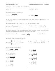
(a) (b)<br />
FIG. 14-125 Experimental pressure measured by Calvert as a function of gas<br />
velocity and liquid loading for (a) horizontal gas flow through vertical mesh and<br />
(b) gas upflow through horizontal mesh. Mesh thickness was 10 cm with 2.8-mm<br />
wire and void fraction of 98.2 percent, crimped in alternating directions. To convert<br />
meters per second to feet per second, multiply by 3.281; to convert centimeters<br />
to inches, multiply by 0.394. (Calvert, Yung, and Leung, NTIS Publ.<br />
PB-248050, 1975.)<br />
Table 20-41 [Chemical Engineers’ Handbook, 5th ed.)], showing<br />
the minimum size of particles collectible in different types of scrubbers<br />
at reasonably high efficiencies, is a good selection guide.<br />
Cyclonic spray towers can effectively remove liquid particles down<br />
to around 2 to 3 µm. Figures 20-112 and 20-113 (Chemical Engineers’<br />
Handbook, 5th ed.), giving target efficiency between spray<br />
drop size and particle size as calculated by Stairmand or Johnstone<br />
and Roberts, should be considered in selecting spray atomization for<br />
the most efficient tower operation. Figure 14-126 gives calculated<br />
particle cut size as a function of tower height (or length) for vertical<br />
countercurrent spray towers and for horizontal-gas-flow, verticalliquid-flow<br />
cross-current spray towers with parameters for liquid<br />
drop size. These curves are based on physical properties of standard<br />
air and water and should be used under conditions in which these are<br />
reasonable approximations. Lack of uniform liquid distribution or<br />
liquid flowing down the walls can affect the performance, requiring<br />
empirical correction factors. Calvert (R-10) suggests that a correction<br />
factor of 0.2 be used in small-diameter scrubbers to account for the<br />
liquid on the walls, i.e., let Q L/Q g = 0.2 (Q L/Q g) actual. Many more complicated<br />
wet scrubbers employ a combination of sprays or liquid<br />
atomization, cyclonic action, baffles, and targets. These combinations<br />
are not likely to be more efficient than similar devices previously discussed<br />
that operate at equivalent pressure drop. The vast majority of<br />
wet scrubbers operate at moderate pressure drop [8 to 15 cm (3 to 6<br />
in) of water or 18 to 30 cm (7 to 12 in) of water] and cannot be<br />
expected to have high efficiency on particles smaller than 10 µm or 3<br />
to 5 µm respectively. Fine and submicrometer particles can be captured<br />
efficiently only in wet scrubbers having high energy input<br />
such as venturi scrubbers, two-phase eductor scrubbers, and fluxforce-condensation<br />
scrubbers.<br />
Venturi Scrubbers One type of venturi scrubber is illustrated in<br />
Fig. 17-48. Venturi scrubbers have been used extensively for collecting<br />
fine and submicrometer solid particulate, condensing tars and<br />
mists, and mixtures of liquids and solids. To a lesser extent, they have<br />
also been used for simultaneous gas absorption, although Lundy [Ind.<br />
Eng. Chem., 50, 293 (1958)] indicates that they are generally limited<br />
to three transfer units. They have been used to collect submicrometer<br />
chemical incinerator fume and mist as well as sulfuric and phosphoric<br />
acid mists. The collection efficiency of a venturi scrubber is highly<br />
dependent on the throat velocity or pressure drop, the liquid-to-gas<br />
ratio, and the chemical nature of wettability of the particulate. Throat<br />
velocities may range from 60 to 150 m/s (200 to 500 ft/s). Liquid injection<br />
rates are typically 0.67 to 1.4 m 3 /1000 m 3 of gas. A liquid rate of<br />
1.0 m 3 per 1000 m 3 of gas is usually close to optimum, but liquid rates<br />
as high as 2.7 m 3 (95 ft 3 ) have been used. Efficiency improves with<br />
increased liquid rate but only at the expense of higher pressure drop<br />
and energy consumption. Pressure-drop predictions for a given efficiency<br />
are hazardous without determining the nature of the particulate<br />
and the liquid-to-gas ratio. In general, particles coarser than 1 µm<br />
can be collected efficiently with pressure drops of 25 to 50 cm of<br />
water. For appreciable collection of submicrometer particles, pressure<br />
drops of 75 to 100 cm (30 to 40 in) of water are usually required.<br />
When particles are appreciably finer than 0.5 µm, pressure drops of<br />
175 to 250 cm (70 to 100 in) of water have been used.<br />
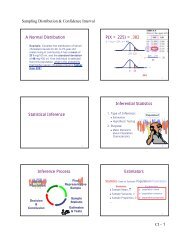
(a) (b)<br />
FIG. 14-126 Predicted spray-tower cut diameter as a function of sprayed length and spray droplet size for (a) vertical-countercurrent<br />
towers and (b) horizontal-cross-flow towers per Calvert [J. Air Pollut. Control Assoc., 24, 929 (1974)]. Curve 1 is for<br />
200-µm spray droplets, curve 2 for 500-µm spray, and curve 3 for 1000-µm spray. Q L/QC is the volumetric liquid-to-gas ratio,<br />
L liquid/m 3 gas, and uG is the superficial gas velocity in the tower. To convert liters per cubic meter to cubic feet per cubic foot,<br />
multiply by 10 −3 .