Packed Bed flooding.pdf - Youngstown State University's Personal ...
Packed Bed flooding.pdf - Youngstown State University's Personal ...
Packed Bed flooding.pdf - Youngstown State University's Personal ...

You also want an ePaper? Increase the reach of your titles
YUMPU automatically turns print PDFs into web optimized ePapers that Google loves.
14-120 EQUIPMENT FOR DISTILLATION, GAS ABSORPTION, PHASE DISPERSION, AND PHASE SEPARATION<br />
alternate directions, which increases voidage, reduces sheltering and<br />
increases target efficiency per layer, and gives a lower pressure drop<br />
per unit length; and (3) spiral-wound layers which reduce pressure<br />
drop by one-third, but fluid creep may lead to higher entrainment.<br />
Some small manufacturers of plastic meshes may offer other weaves<br />
claimed to be superior. The filament size can vary from about 0.15<br />
mm (0.006 in) for fine-wire pads to 3.8 mm (0.15 in) for some plastic<br />
fibers. Typical pad thickness varies from 100 to 150 mm (4 to 6 in), but<br />
occasionally pads up to 300 mm (12 in) thick are used. A typical wire<br />
diameter for standard stainless mesh is 0.28 mm (0.011 in), with a finished<br />
mesh density of 0.15 g/cm3 (9.4 lb/ft3 ). A lower mesh density<br />
may be produced with standard wire to give 10 to 20 percent higher<br />
flow rates.<br />
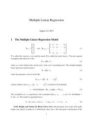
Figure 14-120 presents an early calculated estimate of mesh efficiency<br />
as a fraction of mist-particle size. Experiments by Calvert<br />
(R-12) confirm the accuracy of the equation of Bradie and Dickson<br />
( Joint Symp. Proc. Inst. Mech. Eng./Yorkshire Br. Inst. Chem. Eng.,<br />
1969, pp. 24–25) for primary efficiency in mesh separators:<br />
η=1 − exp(−2/3)πalηi) (14-232)<br />
where η is the overall collection efficiency for a given-size particle; l is<br />
the thickness of the mesh, cm, in the direction of gas flow; a is the surface<br />
area of the wires per unit volume of mesh pad, cm2 /cm3 ; and η i,<br />
the target collection efficiency for cylindrical wire, can be calculated<br />
from Fig. 17-39 or the impaction data of Golovin and Putnam [Ind.<br />
Eng. Chem., 1, 264 (1962)]. The factor 2/3, introduced by Carpenter<br />
and Othmer [Am. Inst. Chem. Eng. J., 1, 549 (1955)], corrects for the<br />
fact that not all the wires are perpendicular to the gas flow and gives<br />
the projected perpendicular area. If the specific mesh surface area a is<br />
not available, it can be calculated from the mesh void area ε and the<br />
mesh wire diameter dw in cm, a = 4(1 −ε)/dw.<br />
York and Poppele (R-17) have stated that factors governing maximum<br />
allowable gas velocity through the mesh are (1) gas and liquid<br />
density, (2) liquid surface tension, (3) liquid viscosity, (4) specific wire<br />
surface area, (5) entering-liquid loading, and (6) suspended-solids<br />
content. York (R-18) has proposed application of the Souders-Brown<br />
equation [Eq. (14-226)] for correlation of maximum allowable gas<br />
velocity with values of K for most cases of 0.1067 m/s to give U in m/s<br />
(0.35 for ft/s). When liquid viscosity or inlet loading is high or the liquid<br />
is dirty, the value of K must be reduced. Schroeder (M.S. thesis,<br />
Newark College of Engineering, 1962) found lower values for K necessary<br />
when liquid surface tension is reduced such as by the presence<br />
of surfactants in water. Ludwig (Applied Process Design for Chemical<br />
and Petrochemical Plants, 2d ed., vol. I, Gulf, Houston, 1977, p. 157)<br />
recommends reduced K values of (0.061 m/s) under vacuum at an<br />
absolute pressure of 6.77 kPa (0.98 lbf/in2 ) and K = 0.082 m/s at 54 kPa<br />
(7.83 lbf/in2 ) absolute. Most manufacturers suggest setting the design<br />
velocity at three-fourths of the maximum velocity to allow for surges in<br />
gas flow.<br />
York and Poppele (R-17) have suggested that total pressure drop<br />
through the mesh is equal to the sum of the mesh dry pressure drop<br />
FIG. 14-120 Collection efficiency of wire-mesh separator; 6-in thickness, 98.6<br />
percent free space, 0.006-in-diameter wire used for experiment points. Curves<br />
calculated for target area equal to 2 and 3 times the solids volume of packing. To<br />
convert inches to millimeters, multiply by 25.4.<br />
plus an increment due to the presence of liquid. They considered the<br />
mesh to be equivalent to numerous small circular channels and used<br />
the D’Arcy formula with a modified Reynolds number to correlate<br />
friction factor (see Fig. 14-121) for Eq. (14-233) giving dry pressure<br />
drop.<br />
∆Pdry = flaρgUg 2 /981 ε 3 (14-233)<br />
where ∆P is in cm of water; f is from Fig. (14-121); ρg is the gas density,<br />
g/cm 3 ; U g is the superficial gas velocity, cm/s; and ε is the mesh<br />
porosity or void fraction; l and a are as defined in Eq. (14-232). Figure<br />
14-121 gives data of York and Poppele for mesh crimped in the same<br />
and alternating directions and also includes the data of Satsangee, of<br />
Schuring, and of Bradie and Dickson.<br />
The incremental pressure drop for wet mesh is not available for all<br />
operating conditions or for mesh of different styles. The data of York<br />
and Poppele for wet-mesh incremental pressure drop, ∆P L in cm of<br />
water, are shown in Fig. 14-122 or parameters of liquid velocity L/A,<br />
defined as liquid volumetric flow rate, cm 3 /min per unit of mesh crosssectional<br />
area in cm 2 ; liquid density ρL is in g/cm 3 .<br />
York generally recommends the installation of the mesh horizontally<br />
with upflow of gas as in Fig. 14-110f; Calvert (R-12) tested the<br />
mesh horizontally with upflow and vertically with horizontal gas flow.<br />
He reports better drainage with the mesh vertical and somewhat<br />
higher permissible gas velocities without reentrainment, which is contrary<br />
to past practice. With horizontal flow through vertical mesh, he<br />
found collection efficiency to follow the predictions of Eq. (14-232)<br />
up to 4 m/s (13 ft/s) with air and water. Some reentrainment was<br />
encountered at higher velocities, but it did not appear serious until<br />
velocities exceeded 6.0 m/s (20 ft/s). With vertical upflow of gas,<br />
entrainment was encountered at velocities above and below 4.0 m/s<br />
(13 ft/s), depending on inlet liquid quantity (see Fig. 14-123). Figure<br />
14-124 illustrates the onset of entrainment from mesh as a function of<br />
liquid loading and gas velocity and the safe operating area recommended<br />
by Calvert. Measurements of dry pressure drop by Calvert<br />
gave values only about one-third of those predicted from Eq. (14-<br />
233). He found the pressure drop to be highly affected by liquid load.<br />
The pressure drop of wet mesh could be correlated as a function of<br />
Ug 1.65 and parameters of liquid loading L/A, as shown in Fig. 14-125.<br />
As indicated previously, mesh efficiency drops rapidly as particles<br />
decrease in size below 5 µm. An alternative is to use two mesh pads in<br />
series. The first mesh is made of fine wires and is operated beyond the<br />
FIG. 14-121 Value of friction factor f for dry knitted mesh for Eq. (14-233).<br />
Values of York and Poppele [Chem. Eng. Prog., 50, 421 (1954)] are given in<br />
curve 1 for mesh crimped in the alternating direction and curve 2 for mesh<br />
crimped in the same direction. Data of Bradie and Dickson (Joint Symp. Proc.<br />
Inst. Mech. Eng./Yorkshire Br. Inst. Chem. Eng., 1969, pp. 24–25) are given in<br />
curve 3 for layered mesh and curve 4 for spiral-wound mesh. Curve 5 is data of<br />
Satsangee (M.S. thesis, Brooklyn Polytechnic Institute, 1948) and Schurig<br />
(D.Ch.E. dissertation, Brooklyn Polytechnic Institute, 1946). (From Calvert,<br />
Yung, and Leung, NTIS Publ. PB-248050, 1975.)