Packed Bed flooding.pdf - Youngstown State University's Personal ...
Packed Bed flooding.pdf - Youngstown State University's Personal ...
Packed Bed flooding.pdf - Youngstown State University's Personal ...

You also want an ePaper? Increase the reach of your titles
YUMPU automatically turns print PDFs into web optimized ePapers that Google loves.
14-114 EQUIPMENT FOR DISTILLATION, GAS ABSORPTION, PHASE DISPERSION, AND PHASE SEPARATION<br />
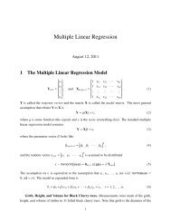
FIG. 14-107 Overall integrated penetration as a function of particle-size distribution<br />
and collector cut diameter when B = 2 in Eq. (14-224). (Calvert, Goldshmid,<br />
Leith, and Mehta, NTIS Publ. PB-213016, 213017, 1972.)<br />
required from the collection device being considered. Therefore, an<br />
experimental plot of aerodynamic cut size for each collection device<br />
versus operating parameters can be used to determine the device suitability.<br />
Collection Equipment<br />
Gravity Settlers Gravity can act to remove larger droplets. Settling<br />
or disengaging space above aerated or boiling liquids in a tank or<br />
spray zone in a tower can be very useful. If gas velocity is kept low, all<br />
particles with terminal settling velocities (see Sec. 6) above the gas<br />
velocity will eventually settle. Increasing vessel cross section in the<br />
settling zone is helpful. Terminal velocities for particles smaller than<br />
50 µm are very low and generally not attractive for particle removal.<br />
Laminar flow of gas in long horizontal paths between trays or shelves<br />
on which the droplets settle is another effective means of employing<br />
gravity. Design equations are given in Sec. 17 under “Gas-Solids Separations.”<br />
Settler pressure drop is very low, usually being limited to<br />
entrance and exit losses.<br />
Centrifugal Separation Centrifugal force can be utilized to<br />
enhance particle collection to several hundredfold that of gravity. The<br />
design of cyclone separators for dust removal is treated in detail in<br />
Sec. 17 under “Gas-Solids Separations,” and typical cyclone designs<br />
are shown in Fig. 17-43. Dimension ratios for one family of cyclones<br />
are given in Fig. 17-36. Cyclones, if carefully designed, can be more<br />
efficient on liquids than on solids since liquids coalesce on capture<br />
and are easy to drain from the unit. However, some precautions not<br />
needed for solid cyclones are necessary to prevent reentrainment.<br />
Tests by Calvert (R-12) show high primary collection efficiency on<br />
droplets down to 10 µm and in accordance with the efficiency equations<br />
of Leith and Licht [Am. Inst. Chem. Eng. Symp. Ser., 68(126),<br />
196–206 (1972)] for the specific cyclone geometry tested if entrainment<br />
is avoided. Typical entrainment points are (1) creep along the<br />
gas outlet pipe, (2) entrainment by shearing of the liquid film from the<br />
walls, and (3) vortex pickup from accumulated liquid in the bottom<br />
(Fig. 14-108a). Reentrainment from creep of liquid along the top of<br />
the cyclone and down the outlet pipe can be prevented by providing<br />
the outlet pipe with a flared conical skirt (Fig. 14-108b), which provides<br />
a point from which the liquid can drip without being caught in<br />
the outlet gas. The skirt should be slightly shorter than the gas outlet<br />
pipe but extend below the bottom of the gas inlet. The cyclone inlet<br />
gas should not impinge on this skirt. Often the bottom edge of the<br />
skirt is V-notched or serrated.<br />
(a)<br />
FIG. 14-108 (a) Liquid entrainment from the bottom of a vessel by centrifugal<br />
flow. (Rietema and Verver, Cyclones in Industry, Elsevier, Amsterdam, 1961.)<br />
(b) Gas-outlet skirt for liquid cyclones. (Stern et al., Cyclone Dust Collectors,<br />
American Petroleum Institute, New York, 1955.)<br />
Reentrainment is generally reduced by lower inlet gas velocities.<br />
Calvert (R-12) reviewed the literature on predicting the onset of<br />
entrainment and found that of Chien and Ibele (ASME Pap. 62-<br />
WA170) to be the most reliable. Calvert applies their correlation to a<br />
liquid Reynolds number on the wall of the cyclone, NRe,L = 4QL/hivL,<br />
where QL is the volumetric liquid flow rate, cm 3 /s; hi is the cyclone<br />
inlet height, cm; and vL is the kinematic liquid viscosity, cm 2 /s. He<br />
finds that the onset of entrainment occurs at a cyclone inlet gas velocity<br />
Vci, m/s, in accordance with the relationship in Vci = 6.516 − 0.2865<br />
ln NRe,L.<br />
Reentrainment from the bottom of the cyclone can be prevented in<br />
several ways. If a typical long-cone dry cyclone is used and liquid is<br />
kept continually drained, vortex entrainment is unlikely. However, a<br />
vortex breaker baffle in the outlet is desirable, and perhaps a flat disk<br />
on top extending to within 2 to 5 cm (0.8 to 2 in) of the walls may be<br />
beneficial. Often liquid cyclones are built without cones and have<br />
dished bottoms. The modifications described earlier are definitely<br />
needed in such situations. Stern, Caplan, and Bush (Cyclone Dust<br />
Collectors, American Petroleum Institute, New York, 1955) and<br />
Rietema and Verver (in Tengbergen, Cyclones in Industry, Elsevier,<br />
Amsterdam, 1961, chap. 7) have discussed liquid-collecting cyclones.<br />
As with dust cyclones, no reliable pressure-drop equations exist (see<br />
Sec. 17), although many have been published. A part of the problem<br />
is that there is no standard cyclone geometry. Calvert (R-12) experimentally<br />
obtained ∆P = 0.000513 ρg(Qg/hiWi) 2 (2.8hiwi/d o 2 ), where ∆P<br />
is in cm of water; ρg is the gas density, g/cm 3 ; Qg is the gas volumetric<br />
flow rate, cm 3 /s; hi and wi are cyclone inlet height and width respectively,<br />
cm; and do is the gas outlet diameter, cm. This equation is in the<br />
same form as that proposed by Shepherd and Lapple [Ind. Eng.<br />
Chem., 31, 1246 (1940)] but gives only 37 percent as much pressure<br />
drop.<br />
Liquid cyclone efficiency can be improved somewhat by introducing<br />
a coarse spray of liquid in the cyclone inlet. Large droplets which<br />
are easily collected collide with finer particles as they sweep the gas<br />
stream in their travel to the wall. (See subsection “Wet Scrubbers”<br />
regarding optimum spray size.) Cyclones may also be operated wet to<br />
improve their operation on dry dust. Efficiency can be improved<br />
through reduction in entrainment losses since the dust particles<br />
become trapped in the water film. Collision between droplets and<br />
dust particles aids collection, and adequate irrigation can eliminate<br />
problems of wall buildup and fouling. The most effective operation is<br />
obtained by spraying countercurrently to the gas flow in the cyclone<br />
inlet duct at liquid rates of 0.7 to 2.0 L/m 3 of gas. There are also many<br />
proprietary designs of liquid separators using centrifugal force, some<br />
of which are illustrated in Fig. 14-109. Many of these were originally<br />
(b)