- Page 1 and 2:
ABOV SEMICONDUCTOR Co., Ltd.8-BIT M
- Page 3 and 4:
MC95FB204VERSION 0.2 Preliminary (S
- Page 5 and 6:
MC95FB20410.5 Interrupt Sequence ..
- Page 7 and 8:
MC95FB204List of FiguresFigure 1.1
- Page 9 and 10:
MC95FB204List of TablesTable 1-1 Or
- Page 11 and 12:
MC95FB2041.3 Ordering InformationTa
- Page 13 and 14:
MC95FB204Figure 1.2 Single Programm
- Page 15 and 16:
MC95FB204MC95FB2043. Pin Assignment
- Page 17 and 18:
MC95FB204Figure 4.2 20 pin TSSOP pa
- Page 19 and 20:
MC95FB2046. Port Structures6.1 Gene
- Page 21 and 22:
MC95FB2047. Electrical Characterist
- Page 23 and 24:
MC95FB204Note) -STOP1: WDT running
- Page 25 and 26:
MC95FB2047.9 AC CharacteristicsTabl
- Page 27 and 28:
MC95FB2047.11 Typical Characteristi
- Page 29 and 30:
MC95FB204FFFFH0FFFH4KBytes0000HFigu
- Page 31 and 32:
MC95FB2047FH7F776F7E766E7D756D7C 7B
- Page 33 and 34:
MC95FB204July 17, 2012 Ver.1.7 33
- Page 35 and 36:
MC95FB204Address Function Symbol R/
- Page 37 and 38:
MC95FB204Address Function Symbol R/
- Page 39 and 40:
MC95FB204ACF0Auxiliary Carry FlagGe
- Page 41 and 42:
MC95FB2049.2.6 Register MapTable 9-
- Page 43 and 44:
MC95FB2049.4 P1 Port9.4.1 P1 Port D
- Page 45 and 46:
MC95FB2049.5 P2 Port9.5.1 P2 Port D
- Page 47 and 48:
MC95FB20410. Interrupt Controller10
- Page 49 and 50:
MC95FB20410.3 Block DiagramIEDS0IE[
- Page 51 and 52:
MC95FB2041IE.EA Flag 1IEx.y 123Pr
- Page 53 and 54:
MC95FB20410.7 Multi InterruptIf two
- Page 55 and 56:
MC95FB20410.10 Saving/Restore Gener
- Page 57 and 58:
MC95FB204IE2 AAH R/W 00H Interrupt
- Page 59 and 60:
MC95FB204R R R/W R/W R/W R/W R/W R/
- Page 61 and 62:
MC95FB20411. CC/CV BlockCC/CV means
- Page 63 and 64:
MC95FB204When the current of R SENS
- Page 65 and 66:
MC95FB20412. Clock Generator12.1 Ov
- Page 67 and 68:
MC95FB204Note) by CBYS bit, reflect
- Page 69 and 70:
MC95FB20413.4 Bit Interval Timer Re
- Page 71 and 72:
MC95FB204WDTMR 8D R/W 00H Watch Dog
- Page 73 and 74:
MC95FB20415. Timer/PWM15.1 Overview
- Page 75 and 76: MC95FB204Match with T0DR/T1DRT0DR/T
- Page 77 and 78: MC95FB204T0CRT0EN T0PE CAP0 T0CK2 T
- Page 79 and 80: MC95FB204T0CRT0EN T0PE CAP0 T0CK2 T
- Page 81 and 82: MC95FB204T1CR[1:0] = 10 H(2us)PWM1H
- Page 83 and 84: MC95FB204T0 (Timer 0 Register: Read
- Page 85 and 86: MC95FB204Initial value : 00HCDR1[7:
- Page 87 and 88: MC95FB20416.2 Block Diagram÷2fxPre
- Page 89 and 90: MC95FB204SET ADCM2Select ADC Clock
- Page 91 and 92: MC95FB204ADDM11 ADDM10 ADDM9 ADDM8
- Page 93 and 94: MC95FB20417. Power Down Operation17
- Page 95 and 96: MC95FB20417.4 STOP modeThe power co
- Page 97 and 98: MC95FB20417.5.1 Register MapTable 1
- Page 99 and 100: MC95FB20418.4 RESET Noise Canceller
- Page 101 and 102: MC95FB204:VDD Input:Internal OSCRes
- Page 103 and 104: MC95FB20419. On-chip Debug System19
- Page 105 and 106: MC95FB204Figure 19.2 10-bit transmi
- Page 107 and 108: MC95FB204Acknowledge bittransmissio
- Page 109 and 110: MC95FB20420.2.2 Register descriptio
- Page 111 and 112: MC95FB2047 6 5 4 3 2 1 0ARL7 ARL6 A
- Page 113 and 114: MC95FB20420.3 Memory map20.3.1 Flas
- Page 115 and 116: MC95FB204Master ResetPage Buffer Re
- Page 117 and 118: Step 5. Set erase mode. FMR:1001_00
- Page 119 and 120: MC95FB20420.4.2 Summary of Flash Pr
- Page 121 and 122: MC95FB20420.6 SecurityMC95FB204 pro
- Page 123 and 124: MC95FB20422. APPENDIX22.1 Instructi
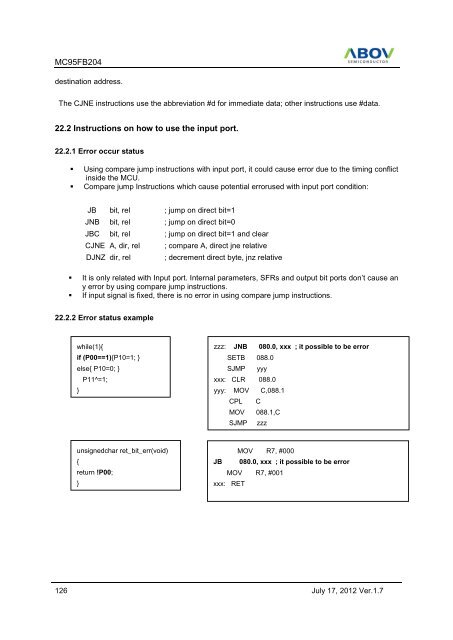
- Page 125: MC95FB204SETB C Set carry 1 1 D3SET