Create successful ePaper yourself
Turn your PDF publications into a flip-book with our unique Google optimized e-Paper software.
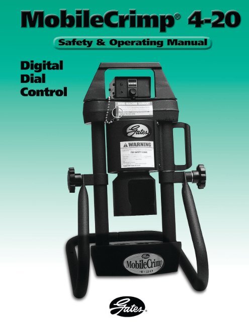
®Serial No. _______________(Located on front top of cylinder)Date of Purchase _________ContentsIdentification List ...........................................................................................2Setup ..............................................................................................................3Hose Preparation ............................................................................................7Operating Instructions ....................................................................................9Measuring and Adjusting the Crimp Diameter ..............................................13Maintenance .................................................................................................14Troubleshooting ............................................................................................15Replacement Parts List ..................................................................................16Warranty ................................................................................inside back coverMobileCrimp®14<strong>20</strong>1
®Identification ListDieMolykote and BrushPressure PlateStandCrimperHose AssemblyClamps.05 Allen WrenchLiterature PacketMagnet2MobileCrimp®4<strong>20</strong>
®Setup1. Unpack carton.• Remove crimper, pressure plate (1),nylon-covered hose assembly (1),literature envelope (1), stand (2 pieces),magnet (1) .05 Allen wrench (1) andMolykote lubricant (1) from shippingcarton. Locate the serial numberassigned to the crimper on the top frontof the cylinder and record on page onefor future reference.2. Attach crimper to the stand.• Place crimper on flat, well-supportedsurface (such as the top of a workbenchor the bed of a service vehicle) with thehandle to the right.• Remove two (2) knobs, flat washers (2)and spacer (1) from crimper pivot bolts.• Replace spacer, flat washers and knobs.Do not tighten knobs.Left SidespacerRight Side• Lift crimper and allow stand to swingdown onto the surface. Tighten knobs.• Slide the two halves of the standtogether and attach to the crimperat the pivot bolts.MobileCrimp®4<strong>20</strong>3
®3. Fasten crimper to work surfacebefore use (to avoid damage tomachine or personal injury becausean unsecured machine can fall).• Position crimper so that mounting holesare approximately 7" to 8" from theedge of the work surface.• Mark the drilling location using themounting holes as a guide (see illustrationbelow).Edge ofworksurface(2) 5 /16" diameter holes4. Attach pump to crimper.• Place pump near crimper.• Connect hose assembly to the pumpport (3/8" NPT threads). Pipe sealantmay be used to seal connection. (Forbest connection, use Gates’ QuickDisconnect couplings, G95311-0606and G95321-0606, sold separately.)7 1 /2" 11"• Drill two 5/16" diameter holes.• Use mounting holes or clamps to fastenstand to work surface.clamps• Connect opposite end to the adapteron crimper.mounting holesTo avoid damage tothe machine or injuryto you, ALWAYS fastenthe crimper to the worksurface before you attempt to crimp.5. Check pump oil level.• Pump comes with oil in reservoir.• Check proper oil level per pumpoperating manual instructions or theMaintenance Section (p. 14) of thismanual.6. Connect pump to power outlet.• For 115V connection, plug power cordinto a properly grounded and rated circuit(see inside cover for circuit requirements).• For vehicle battery connection, seepump operating manual.4MobileCrimp®4<strong>20</strong>
®7. Bleed air from system.• Tilt crimper forward so adapter is atits highest point.CAUTIONKeep away from all moving parts!If bodily contact with a movingpart occurs, immediately releasethe pump power “on“ switch.• Turn the knob on the controller to asetting of 400, which allows the ramto extend approximately 1".• When the light comes on and buzzersounds, immediately release “on” switchallowing ram to fully retract. NOTE: Iflight and buzzer are faint or do notwork, the controller batteries may needreplacement. See “Maintenance” sectionof this manual.• Repeat a minimum of five (5) times tobleed air completely.8. Place crimper in comfortableworking position.• See photo below for suggested workingposition.• Turn pump on by pressing and holdingthe power ”on“ switch, (see pumpoperating manual for switch location)which extends the ram.IMPORTANTDo not operate crimper inhorizontal position because dieswill become unstable.Note: It’s a goodidea to place a rubbermat on the floornear the crimper toreduce the chance of damaging adie if dropped and improve operatorcomfort.MobileCrimp®4<strong>20</strong>5
®9. Calibrate.• Before crimping a hose assembly,check calibration.Calibration is the proper relationship betweena setting and the crimp diameter. It should bechecked at least monthly, possibly weekly ordaily, if crimper has been used heavily orabused.• Place the <strong>MC</strong>33 die set into thedie cone and install pressure plate.• If the crimp diameter is within this range, noadjustment is necessary.• If the crimp diameter is not within this range,the crimper must be calibrated.• To get a smaller crimp diameter,change the setting to a smaller number.• To get a larger crimp diameter,change the setting to a larger number.• For every .001" change in crimp diameter,change the setting by 002. For example, toincrease the crimp diameter by .002", increaseyour setting from 245 to 247.• Turn the knob to this new settingand crimp a new coupling.• After the correct diameter is achieved, pull theplastic cap from the knob.• Turn the knob to a setting of 245.• Loosen the two (2) set screws in the brass knob1/4 to 1/2 turn using a .05” Allen wrench.Note: Rotating the knob on front of switch box clockwise willincrease the number; counterclockwise will decrease the number.When changing the setting, always move to a highternumber then down to the desired setting. (Example: To changefrom <strong>20</strong>0 to 245, move dial up to 300 then down to 245.)• Insert an 8G MegaCrimp ® coupling into thedie set.• Turn the brass knob either clockwise or counterclockwiseto get the setting back to 245.6• Complete the crimp.• Remove the coupling and measure the crimpdiameter, which should measure 1.000"±.003". To properly measure crimp diameter,refer to page 13.MobileCrimp®4<strong>20</strong>• Tighten the set screws and replacethe plastic cap.• Crimper is now calibrated.
®OperatingInstructions1. Select correct die set.• Using Gates crimp data chart#35019 (Ind), 428-7365 (Auto) orecrimp, select correct die set for thehose and coupling being crimped.• Using the magnet, place the die setinto the die cone.die set• Remove magnet by lifting the ”T”handle, making sure the top of thedie fingers are even.2. Lubricate and load die.• Swing cylinder to ”die loading” position.• Apply thin layer of Molykote* lubeto the inside surface of the die cone.Re-apply lube whenever surfacebecomes shiny.• Apply a thin layer of Molykote lubeto the top of the die set.Important Note:Lubricants should bereapplied to metal-tometalsliding surfaceswhenever the surface becomes shiny.Failure to do this reduces the life ofthe dies and cone. Excessive wear onthese components produces poorlyperforming hose assemblies thatcould blow apart and result in injury.MobileCrimp®4<strong>20</strong>* Use only Gates Molykote lube for proper operationor Gates-recommended grease.9
®3. Select correct setting.• Using Gates crimp data chart #35019(Ind), 428-7365 (Auto) or ecrimp, selectcorrect setting for the hose and couplingbeing crimped.4. <strong>Dial</strong> in setting and installpressure plate.• Turn the knob on the controller tothe selected setting.settinglocking switch• Settings are approximate and mayneed to be adjusted. See Measuringand Adjusting the Crimp DiameterSection (p. 13).• If crimping multiple assemblies, movethe locking switch to the right to holdthe setting. Moving switch to the leftallows the setting to be changed.• Place the pressure plate onto the die set.IMPORTANTSAFETY NOTE:All settings are approximate!Machining tolerancesexist for each crimper, die setand supporting piece of equipmentwhich will affect your actual setting.Always check the crimp diameter toensure that it is within the publishedlimits. Record your actual crimpersetting to achieve the specifiedcrimp diameter for future use.Failure to heed this message couldresult in improperly made assemblies,blowing the hose out of thefittings at high pressure, and risk offire and/or serious injury.10MobileCrimp®4<strong>20</strong>
®5. Insert hose assembly.• Insert assembly from the bottom of thedie cone up through the die set.• When crimping bent tube and block-stylecouplings, keep thread end aligned withnotch in pressure plate.• Locate the top of the ferruleapproximately 1/16"below thetop of the die set.6. Swing cylinder into crimpingposition.• Using the handle, swing cylindertoward you and lock into place withlock pin.IMPORTANTFor GS couplings, make surethe top of the ferrule restsagainst the hex or roundshoulder of the coupling.MobileCrimp®4<strong>20</strong>11
®TroubleshootingAll equipment is tested for proper performancebefore it is shipped from the factory.However, if you experience any difficulties,check the list below to help restore equipmentto proper operating standards.Problem• Ram will not fully extend.• Ram will not retract.• Pump motor will not start.• Setting will not change.• Light and buzzer do not work.Correction• Check hydraulic oil level in pump reservoir.• Hydraulic oil temperature must be within+40º F and +1<strong>20</strong>º F.• Unplug pump from electrical outlet.(WARNING: pump must be unpluggedto avoid risk of injury.)• Slowly and carefully loosen hose at pump.Be prepared to catch oil as it escapes. Ifram retracts, pump valve may be stuck orneed replacement.• Check electrical connections.• Locking switch may be engaged.Move switch to the left.• Replace the controller batteries. SeeMaintenance Section.• Replace controller.MobileCrimp®4<strong>20</strong>15
®ReplacementParts List16MobileCrimp®4<strong>20</strong>* Not shown
®NotesMobileCrimp®4<strong>20</strong>
®NotesMobileCrimp®4<strong>20</strong>
®NotesMobileCrimp®4<strong>20</strong>
®NotesMobileCrimp®4<strong>20</strong>
®Two-Year Limited Warranty on EquipmentFor two years from the date of shipment of the equipment to the original user, The GatesRubber Company will, at its option, replace or repair any unit which proves to be defectivein material or workmanship, or both, at no cost to the original user of the equipment. Thisis the exclusive remedy. THERE IS NO OTHER EXPRESS OR IMPLIED WARRANTY.ALL INCLUDING THOSE OF MERCHANTABILITY AND FITNESS FOR A PARTICULARPURPOSE, ARE LIMITED TO ONE YEAR FROM DATE OF SHIPMENT OF THEEQUIPMENT TO THE ORIGINAL USER. LIABILITY FOR CONSEQUENTIAL ANDINCIDENTAL DAMAGES UNDER ANY AND ALL WARRANTIES IS EXCLUDED TO THEEXTENT EXCLUSION IS PERMITTED BY LAW. Some states do not allow the exclusion ofincidental or consequential damages, and some states do not allow limitations on how longan implied warranty lasts, so the above limitation and exclusion may not apply to you. Thiswarranty gives you specific legal rights and you may also have other rights which vary fromstate to state. For warranty service, contact Service Department, The Gates RubberCompany, 990 S. Broadway, P.O. Box 5887, Denver, Colorado 80217.How to OrderRepair PartsAll parts for MobileCrimp ® 4-<strong>20</strong> machine listedin current replacement parts price sheets can beordered directly from The Gates Rubber Company,Iola Distribution Center, 999 Michigan Ave.,P.O. Box 606, Iola, KS 66749,Phone (316) 365-6961.When ordering, be sure to include the followinginformation:1. Name of unit shown on front.2. Product number of parts needed.3. Description of parts needed.4. Quantity of parts needed.5. Serial number of machine.For selling prices on inventoried parts, refer toHydraulic Power Crimp Equipment and Parts ListPrice Schedule. Selling prices for parts not shownin these lists will be furnished on request, or partswill be shipped at prevailing prices and you willbe billed accordingly. For information regardingprices, contact your local Gates representative orThe Gates Rubber Company, 990 South Broadway,P.O. Box 5887, Denver, Colorado 80217.When returning inoperable equipment, contactyour Gates sales representative and request areturn goods authorization form. Fill out andsend to:The Gates Rubber CompanyATTN: Service DepartmentUnit 29 Receiving901 S. BroadwayDenver, Colorado 80<strong>20</strong>9-4009MobileCrimp®4<strong>20</strong>
®The world’s most trusted name in belts, hose and hydraulics.The Gates Rubber CompanyP.O. Box 5887Denver, Colorado 80217-5887428-7560 (Auto)35032-DD (Ind)9/02


