MW And LW Noise Reducing Antennas
MW And LW Noise Reducing Antennas
MW And LW Noise Reducing Antennas

You also want an ePaper? Increase the reach of your titles
YUMPU automatically turns print PDFs into web optimized ePapers that Google loves.
<strong>MW</strong> <strong>And</strong> <strong>LW</strong> <strong>Noise</strong> <strong>Reducing</strong> <strong>Antennas</strong>Dallas Lankford7/21/05, rev. 11/22/05<strong>Noise</strong> reducing antennas (also called interference reducing antennas) were originallydeveloped by F. R. W. Strafford in the 1930's and then rediscovered and redeveloped byDenzil Wraight in the early 1990's. Some of the information contained here appeared intwo articles written by Denzil Wraight and me during the summer of 1991 and publishedby The National Radio Club in their bulletin, DX News. (Interestingly, a few years later acrippled commercial coax lead-in version of Strafford's antenna transformer appeared,called the Magnetic Longwire Balun.) A digitized copy of my article is given below inthe appendix of this article. Reprints of both articles may be purchased from TheNational Radio Club at their web site: www.nrcdxas.org/catalog/reprints/ .My main contributions to the rediscovery of Strafford's noise reducing antennas at thattime were to develop antenna and receiver matching transformers which used Amidonferrite toroids (Denzil's transformers used Siemens toroids), to investigate the noisereducing properties of Strafford's antennas at my location, and more recently toinvestigate variants of Strafford' noise reducing vertical antennas.. Denzil foundStrafford's original articles in the early 1990's, developed the first modern Straffordantennas at his location in Germany, and informed me of his findings so that I couldfollow in his footsteps.Strafford's antennas do not reduce noise by being remotely located (far away from yourhouse), which was proposed at about the same time as a method for reducing noise. Butas pointed out in my appendix article, locating a Strafford noise reducing antenna 50 feetaway from my house had almost no affect on the amount of noise reduction. Strafford'santennas are inherently noise reducing and may be located near, even within a few feet of,your house. You should, of course, locate any antenna as far away from power lines aspossible. Later it was claimed that the noise reduction of remotely located antennas withcoax lead-in was due to separating the ground of the primary antenna transformer fromthe receiver ground and/or coax ground. However, I have found that separating thosegrounds only slightly reduces noise, if at all, for Strafford antennas with coax lead-in,both inverted L and vertical antennas. <strong>And</strong> Hall-Patch and Bryant found no evidence ofnoise reduction by separating grounds for beverage antennas and coax lead-in accordingto their Proceedings 1988 article.Figure 4 below is from one of Strafford's articles. I have used the more elaborate receivertransformer (balanced centre-tapped and shielded) on several occasions, but it has nevergiven me any additional noise reduction. The simple receiver transformer version ofFigure 4, without the center tapped receiver transformer, and without shielding betweenthe primary and secondary of the receiver transformer, is what I have always used. It hastypically given 10 to 15 dB or more noise reduction in the 100 kHz to 2 - 3 MHzfrequency range at the houses where I have lived.1
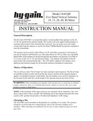
Here is what I wrote in my appendix article belowabout 10 years ago. "According to Strafford, thesekinds of noise reducing antennas are most effectiveagainst nearby noise, i.e., against noise whichoriginates in your house or apartment, in nearbyhouses, in nearby power lines, and so on. <strong>Noise</strong>which will be reduced or eliminated includes, but isnot limited to, TV horizontal oscillator harmonics(HOH) and associated noise sidebands, fluorescentlight noise, air conditioner compressor motor noise,air conditioner fan and heater fan noise, power linenoise, and vacuum cleaner motor noise. Theamount of reduction depends on the type of noise,the location of the noise source relative to theantenna, and perhaps other factors. Strafford saidthat noise reduction with a vertical noise reducingantenna was 30 to 100 (30 dB to 40 dB), but he didnot specify what antenna his noise reducing antenna was compared to. In my experience,the amount of noise reduction (both with my inverted L and with a 30 foot vertical noisereducing antenna) is not as great, namely 3 to 56 (10 dB to 35 dB)compared to myoriginal inverted L. With my noise reducing inverted L, fluorescent light noise wasreduced 10 to 15 dB, TV HOH and associated noise sidebands were reduced about 15 dB,air conditioner compressor motor and AC/heater fan motor noise were virtuallyeliminated, power line noise (60 Hz harmonics) were reduced to the threshold ofdetectability, vacuum cleaner motor noise was reduced more than 30 dB and virtuallyeliminated, and assorted regular noise "pests" of undetermined origin were reduced 15 to25 dB. There is now only one irregular "pest" which ruins daytime <strong>MW</strong> listening, a 40dB + monster which used to "kill" the entire <strong>MW</strong> band except for strong locals. It is stilla serious problem even though it has been reduced about 20 dB. Fortunately it does notappear often, and never at night. Curiously, it is my only remaining noise source wherenulling it with my loop will produce clearer weak signal reception than the noise reducinginverted L."A few things have changed since the above was written. I never hear TV HOH any more.I don't know why. Maybe my neighbor or I had a noisy TV years ago. Or maybe TV'sdon't radiate as much HOH nowadays. But now I often hear digital noise whichoriginates from some of my switching power supplies (laptop computer, inkjet printer,wireless network, etc.), as if to make up for the vanished HOH. My switchers are heardin and around the <strong>MW</strong> band only when ambient power line noise drops to low levels, butare heard regularly above about 10 MHz. When present, my switcher noise is heardapproximately every 65 kHz. My noise reducing antennas reduce but do not completelyeliminate digital noise at lower frequencies. At higher (above about 6 MHz) frequenciesmy noise reducing antennas do not reduce digital noise at all. In both cases, tocompletely eliminate switching power supply digital noise the switchers must beunplugged from the wall socket.2
For a few years I used a noise reducing inverted L antenna as my primary <strong>MW</strong> antenna,both stand alone, and together with a 2 foot air core loop antenna as part of a phased arrayusing simple phasers I developed. Then, beginning about 10 years ago, after I built myfirst Misek phaser, the loop antenna was retired and I used a phased array based on a pairof noise reducing inverted L antennas separated by about 150 feet. As a precautionagainst intermodulation distortion, I shortened the horizontal elements from the 65 feetspecified in my appendix article to 30 feet. Despite what many people believe, bigger(longer) is usually not better, unless you have very low levels of man made noise. If youcan hear man made noise clearly (and I do not mean 20 over S-9 of man made noise),your antenna is long enough. At that time I experimented briefly with noise reducingvertical antennas, but concluded that the signal output was unacceptably low for phasedarrays. There matters remained until a few months ago when I gave noise reducingverticals another try. Figure 5 below is what Strafford recommended for a noise reducingvertical antenna, and probably similar to what I implemented about 10 years ago.However, this time I did not copy Strafford's Figure 5 exactly. Instead of locating theantenna transformer near the top of the vertical antenna, I located it near the bottom,about 15 feet above the ground rod, and used 30 feet of wire above the antennatransformer; see below.3
As a matter of fact I used one of my inverted L's and some 1/4 inch diameter nylon ropeto hoist the vertical contraption over a high branch of a pine tree in my yard. The nylonrope was pulled over the high branch with 20 lb test fishing line which had been shot overthe limb using a 2 ounce lead sinker and sling shot. The 15 foot height of the antennatransformer permits the twin lead to be run high enough above ground level so thatpeople can walk underneath it. I briefly tried a balanced center-tapped receivertransformer and electrostatic shield with one of my verticals which Straffordrecommended, but it gave no additional noise reduction compared to the simple 8 turnbifilar transformer which I normally use.Signal levels for this 15'v+30'v noise reducing vertical antenna have been excellent,4
greater than my 15'v+30'h inverted L's. The verticals reduce noise at least as well as theL's in all cases, and for some daytime groundwave signals my new verticals reduce noiseup to 10 dB more than the L's. Eventually I may reduce the heights of my verticals tominimize potential intermod because the signal levels are greater than necessary at mylocation. My new noise reducing verticals also have better long term null stability fordaytime groundwave signals than my noise reducing inverted L's, and work equally wellwith my big air core loop antennas for <strong>LW</strong> nulls. It is difficult to say if the phasedverticals have better long term null stability for nighttime skywaves than phased invertedL's because of inherent differences (polarization, etc.) between verticals and L's; in anycase, the verticals seem no worse for skywaves. Consequently, my inverted L's have beenretired, and my new noise reducing verticals spaced 150 feet apart are my primary phasedarray for <strong>MW</strong>. For information on the phasers I use go to The Dallas Files atwww.kongsfjord.no .The turns ratio of the antenna transformer of my new noise reducing vertical antenna maybe anything from 3:1 (9:1 impedance ratio) to 4.5:1, or even 5:1. The vertical antennatransformer may be mounted at the ground (d1 = 0). I chose d1 = 15 feet because is waseasy to reach by ladder to provide strain relief for the twin lead (by tying the twin lead tothe trunk of the tree). I have found no difference in noise reduction between mountingthe antenna transformer at the ground or 15 feet up.As pointed out in my appendix article below, the amount of noise reduction of a noisereducing inverted L begins to fall off above 2 or 3 MHz with little, if any, noise reductionobserved above 6 MHz. For a short wave noise reducing antenna Strafford recommendeda 40 foot (horizontal length) doublet. Two versions of Strafford's noise reducing shortwave antenna are given in his Figure 6 below. I briefly used two versions of Figure 6 inthe 21.5 MHz band for experiments with HF phased arrays, but did not investigate theirnoise reducing properties. There have been some claims of noise reduction at SWfrequencies above 6 MHz using coax with an inverted L instead of twin lead, but that isdoubtful for reasons given by Strafford, and I have not observed any such noise reduction.5
AppendixInverted L <strong>Noise</strong> <strong>Reducing</strong> MF/VLF <strong>Antennas</strong>Dallas LankfordJuly 1991If you could reduce all of your regular MF noise sources and pests by 10 dB to 35 dB andyour VLF noise even more for an outlay of two ferrite toroids, some Teflon pipe threadtape, 25 to 50 feet of zip cord, and an 8 foot ground rod, wouldn't you convert yourinverted L to a noise reducing inverted L antenna?Recently I have been experimenting with some remarkable noise reducing antennas forMF and VLF reception. My current inverted L version of these noise reducing antennas isshown below. I was introduced to these antennas by Denzil Wraight who informed me ofthe Wireless World articles by F. R. W. Strafford, "Screened Aerials," Nov. 25, 1937,pages 516 - 518, and "Vertical or Inverted 'L' Aerials," June 22,1939, pages 575 - 577.Denzil also sent me details of the antenna transformer T1 which he designed. The toroidhe used, a Siemens B64290K0618X830, is apparently not available in the USA, so Idesigned an equivalent transformer using an Amidon FT-114-75 ferrite toroid.My inverted L has a 65 foot horizontal section, one end about 15 feet up at the roof of myhouse, the other end about 25 feet up at a telescoping TV mast, guyed opposite thedirection of the horizontal section. If you already have a longer and/or higher horizontalsection, you may use that. I included the dimensions of my inverted L to give you someminimum dimensions for adequate signal levels. An 8 foot ground rod is sunk in theground directly below the low end by the wall of my house. Use #18 or 16 copper wire toconnect the ground rod to the primary of the antenna transformer Tl. It is a good idea touse some kind of strain relief for mounting the antenna transformer Tl. High wind canwhip the antenna around and eventually break the transformer leads. All of theconnections were soldered. Merely twisting bare wires together is not a good idea.The zip cord may be # 18 stranded lamp cord, speaker wire, or true zip cord. Since the zipcord should be soldered at the secondary of the antenna transformer Tl, you should makesure that both wires of the zip cord pair are copper. With some speaker wire, one of thepairs is stranded aluminum wire. Although I specified 25 to 50 feet of zip cord, you mayuse up to 100 feet of zip cord. For longer lengths of zip cord, you may need to retune thefront end of your receiver.If you use an R-390A or HQ-180A, you may connect the ends (I and II) of the zip corddirectly to the balanced antenna inputs as shown. Be sure to remove the shorting linkbetween the G and adjacent A terminal of the HQ-180A as shown. For unbalancedantenna input terminals, or for use with a VLF converter or accessories such as a phasingunit, you will need an antenna matching transformer.My current antenna matching transformer T2 is an Amidon FT-82-43 ferrite toroid6
wound with 12 trifilar turns of # 22 enameled copper wire. The three wires are woundside by side as shown. As shown, T2 is a balanced to unbalanced 1:4 step up transformer.For some receivers a 1:1 bifilar transformer may provide adequate signal levels. If youuse the antenna with other receivers, you should try both antenna transformers and use theone which gives best signal levels.The antenna transformer Tl is wound on a ferrite toroid made from 75 material, which isa semiconductor. Thus precautions should be taken to prevent the enamel of the windingsfrom being broken and making direct contact with the ferrite material. Otherwise turns ofthe windings will be shorted, and the antenna transformer will not perform as it should.To insulate the toroid I wrapped it with two layers of Teflon pipe thread tape, Harvey'sbrand, type T-l/2 6F - 12. Harvey makes both a thin Teflon tape and a thick Teflon tape.This is the thick Teflon tape. I discussed insulating the toroid with someone at Amidonand they suggested using glass cloth electrical tape (which they sell). A single layer of GCtape was satisfactory. As for weather proofing Tl, you are on your own. I haven't doneanything. For the 43 turn primary you will need about 6 feet of # 20 enameled wire.Fold the 6 foot length into two 3 foot halves, and start winding at the center of theprimary, leaving enough space between turns (in both directions from the center) for the 97
turn secondary windings to fit in between the primary windings. After that, the remainingprimary windings should touch each other on the inner circumference of the toroid.There is just enough space around the inner circumference to accomodate all of thewindings in a single layer. You may have to do some pushing on the primary turns to getthe secondary turns flat in between the primary turns, especially at the innercircumference.For the secondary winding a 3 foot length of # 20 enameled wire is needed. The 6 footprimary length and 3 foot secondary length will give ample excess for about 1 foot leads.I used Teflon spaghetti to insulate the leads, and fixed the ends of the windings withplastic push-through cable ties. I also used a plastic cable tie to mount the finishedantenna transformer to the edge of my roof (a short piece of 2 by 2 fir nailed to the faciamakes a convenient tie point through a hole drilled in the fir) and another cable tiethrough a knot tied in the zip cord for zip cord strain relief.When the inverted L noise reducing antenna described above is compared to an ordinary80 foot inverted L antenna in the <strong>MW</strong> band, the noise reduction can only be described asamazing. In some 37 years of DXing the <strong>MW</strong> band I must have tried at least two dozennoise reducing schemes, and not a single one of the previous schemes had any effect onnoise except for nulling a single noise source with a good loop antenna. The inverted Lnoise reducing antenna does not null noise because it is not a directional antenna; itreduces noise in all directions. According to Strafford, these kinds of noise reducingantennas are most effective against nearby noise, i.e., against noise which originates inyour house or apartment, in nearby houses, in nearby power lines, and so on. <strong>Noise</strong> whichwill be reduced or eliminated includes, but is not limited to, TV horizontal oscillatorharmonics (HOH) and associated noise sidebands, fluorescent light noise, air conditionercompressor motor noise, air conditioner fan and heater fan noise, power line noise, andvacuum cleaner motor noise. The amount of reduction depends on the type of noise, thelocation of the noise source relative to the antenna, and perhaps other factors.Strafford said that noise reduction with a vertical noise reducing antenna was 30 to 100(30 dB to 40 dB), but he did not specify what antenna his noise reducing antenna wascompared to.In my experience, the amount of noise reduction (both with my inverted L and with a 30foot vertical noise reducing antenna) is not as great, namely 3 to 56 (10 dB to 35 dB)compared to my original inverted L. With my noise reducing inverted L, fluorescent lightnoise was reduced 10 to 15 dB, TV HOH and associated noise sidebands were reducedabout 15 dB, air conditioner compressor motor and AC/heater fan motor noise werevirtually eliminated, power line noise (60 Hz harmonics) were reduced to the threshold ofdetectability, vacuum cleaner motor noise was reduced more than 30 dB and virtuallyeliminated, and assorted regular noise "pests" of undetermined origin were reduced 15 to25 dB. There is now only one irregular "pest" which ruins daytime <strong>MW</strong> listening, a 40 dB+ monster which used to "kill" the entire <strong>MW</strong> band except for strong locals. It is still aserious problem even though it has been reduced about 20 dB. Fortunately it does notappear often, and never at night. Curiously, it is my only remaining noise source where8
nulling it with my loop will produce clearer weak signal reception than the noise reducinginverted L.According to Strafford, for maximum noise reduction the antenna transformer Tl shouldbe mounted where the horizontal part of the inverted L changes to vertical. I found nodifference in noise reduction with the antenna transformer Tl mounted at the base of thevertical part of the inverted L. Nevertheless, I currently have my antenna transformer Tl atthe "knee" of the inverted L as shown above just in case there is any advantage to thatconfiguration.I tried my noise reducing inverted L antenna briefly with a borrowed Palomar VLFconverter and got as much or more noise reduction as for the <strong>MW</strong> band. I am not anexperienced VLF listener, so I don't know how this compares with other VLF noisereducing schemes, such as remotely located active broadband whips,or loop antennas.However, I am sure VLF listeners will be pleasantly surprised by the performance of thenoise reducing inverted L antenna.<strong>Noise</strong> reduction begins to falloff in the 2 to 3 MHz range, and by 6 MHz there is little, ifany, difference between the noise reducing inverted L and a standard inverted L antenna.Strafford discusses noise reducing doublet antennas for SW reception in the articlesmentioned above. But I have not tried them.With the noise reducing inverted L antenna perhaps 6 to 10 dB increase in signal levelshas been observed at 15 MHz by reversing the zip cord lead connections (I and II) at theprimary of Tl. After that adjustment was made, the noise reducing inverted L antenna wasan excellent all band antenna, about as good as a standard inverted L antenna at the higherSW frequencies.I have compared my noise reducing inverted L antenna with a noise reducing verticalantenna similar to the one described to me by DenzilWraight. When the vertical wasmounted within a foot or two of the wall of my house, the inverted L was slightly quieter.When the vertical was mounted 50 feet away from the house, the vertical was slightlyquieter. Thus it appears that some additional small amount of noise reduction can beobtained by optimizing the placement of the antenna. For my antennas and noise sources,the amount of additional noise reduction was so small that optimal antenna placementwas not worth the effort. But that may not be the case in general. Since most DXers willhave to compromize with regard to antenna placement, my recommendation is to do thebest you can. Try to maximize the distance between your antenna and obvious noisesources, such as fluorescent lights, TVs, the AC power line to your house, and so on. Thezip cord picks up little, if any, signal at low and medium frequencies, so it can pass nearnoise sources without contributing much, if any, to received noise.I tried several variations on the noise reducing inverted L antenna described above, suchas center tapping and grounding the center tap of the primary of the antenna matchingtransformer T2, and electrostatically shielding the primary of T2 from the secondary ofT2. None of the variations reduced noise further, and center tapping the primary of T2actually increased the noise slightly.9
I would like to express my appreciation to Denzil Wraight for sharing his noise reducingantenna information and discoveries with me which made it possible for me to convertmy inverted L antenna to a noise reducing inverted L antenna. I am convinced that thesekinds of noise reducing antennas will be the wire antennas of choice for most <strong>MW</strong>listeners in the future.10