You also want an ePaper? Increase the reach of your titles
YUMPU automatically turns print PDFs into web optimized ePapers that Google loves.
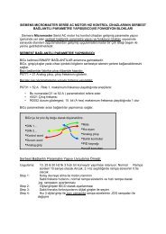
SINAMICS G110Inverter chassis units 0.12 kW to 3 kWSINAMICS G110 chassis units© Siemens AG 20072■ OverviewSINAMICS G110, frame size A (on the right with flat heat sink)SINAMICS G110, frame sizes B and CSINAMICS G110 is a frequency inverter with basic functions fora variety of industrial variable-speed drive applications.The particularly compact SINAMICS G110 inverter operateswith voltage frequency control on single-phase supplies(200 V to 240 V).It is the ideal low-cost frequency inverter solution for the lowerpower range of the SINAMICS family.The following line-side power components are available forSINAMICS G110 inverters:• EMC filters• Line reactors• Fuses• Circuit-breakersThe following accessories are also available:• Operator panels• Mounting accessories• Commissioning toolThe latest technical documentation (catalogs, dimensionaldrawings, certificates, user manuals and operating instructions)is available on the Internet at:http://www.siemens.com/<strong>sinamics</strong>-<strong>g110</strong>and also on CD-ROM CA 01 Vol. 2 “Planning” in the SD configurator,which can be ordered from the following address:■ Benefits7 Simple installation, parameterization, and commissioning7 Robust EMC design7 Large parameter range enables configurations for a widerange of applications7 Simple cable connection7 Scaleable functionality with analog and USS variants7 Low-noise motor operation resulting from high pulsefrequency7 Status information and alarms via the optional BOP(Basic Operator Panel)7 Rapid copying of parameters via the optional BOP7 External options for PC communication and BOP7 Fast, repeatable digital input response time for rapidresponseapplications7 Fine adjustment using a high-resolution 10-bit analog input(analog variants only)7 LED for status information7 Variants with internal EMC filter class A or B7 DIP switches for easy adaptation to 50 Hz or 60 Hzapplications7 DIP switches for simple bus termination for the USS version(RS485)7 Bus-capable serial RS485 interface (USS variants only) enablesintegration in a networked drive system7 2/3-wire method (static/pulsated signals) for universal controlvia digital inputs7 Variable lower voltage limit in DC link to ensure controlled motorbraking if the power failsAccessories (overview)• BOP operator panel• Adapter for installation on DIN rail(frame sizes A and B)• PC inverter connection kit• STARTER commissioning toolLine-side power components (overview)• EMC filter class B with low leakage currents• Additional EMC filter, class B• Line reactorsInternational standards• Fulfills the requirements of the EU low-voltage guidelines•CE mark• Certified to UL and cUL•c-tickhttp://www.siemens.com/automation/CA012/2 Siemens D 11.1· 2007
© Siemens AG 2007SINAMICS G110Inverter chassis units 0.12 kW to 3 kWControlled Power Modules■ ApplicationSINAMICS G110 is especially suited for use with pumps andfans, or as a drive in various industrial sectors, such as the food,textile and packaging industries, as well as for conveyor systems,factory gate and garage door operating mechanisms, andas a universal drive for moving billboards.■ DesignThe SINAMICS G110 inverter chassis units are equipped witha control and power module and provide CPM 110 inverters(Controlled Power Module) with a compact and efficient design.They operate with the latest IGBT technology and digital microprocessorcontrol.The SINAMICS G110 inverter product range consists of the followingvariants and versions:• The analog variant is available in the following versions:- Without EMC filter, with heat sink- Integrated EMC filter, class A/B, with heat sink- Without EMC filter, with flat heat sink (FSA only)- Integrated EMC filter, class B, with flat heat sink (FSA only).• The USS variant (RS485) is available in the following versions:- Without EMC filter, with heat sink- Integrated EMC filter, class A/B, with heat sink- Without EMC filter, with flat heat sink (FSA only)- Integrated EMC filter, class B, with flat heat sink (FSA only).With housing size FSA, cooling is achieved through a heat sinkand natural convection. The FSA design with flat heat sink offersspace-saving and favorable heat dissipation since an additionalheat sink can be installed outside the control cabinet. With housingsizes FSB and FSC, an integrated fan is used to cool the heatsink which has resulted in the compact design.The connections for all inverter variants are easily accessibleand in the same location. To ensure optimum electromagneticcompatibility and easy connection, the line and motor connectionsare located on opposite sides (as with contactors). Thecontrol terminal block does not require screws to install it.The optional BOP (Basic Operator Panel) can be installed withoutthe use of tools.■ Function• Careful handling of the machine mechanical system due to askip frequency band in case of resonance, parameterizableramp up/ramp down times up to 650 s, ramp smoothing, aswell as bringing the inverter into circuit on turning motor(flying start)• Increased installation availability by automatic restart facilityfollowing power failure or fault• Fast current limit (FCL) for trip-free operation in case of suddenload changes• Programmable V/f characteristic (e.g. for synchronousmotors)• Fast DC and compound braking without external brakingresistor• Limitation of DC link voltage by means of the V DCmax controller• Slip compensation, electronic motor potentiometer functionand three fixed speed setpoints• Configurable voltage boost for higher dynamic responsewhen starting and accelerating• Motor holding brake function to control an external mechanicalbrake2Siemens D 11.1· 20072/3
SINAMICS G110Inverter chassis units 0.12 kW to 3 kWControlled Power Modules© Siemens AG 20072■ Technical specificationsPower rangeLine voltageLine frequencyOutput frequencyControlled Power Modules0.12 … 3.0 kW200…240V 1AC±10%47 … 63 Hz0 … 650 Hzcos ϕ ≥ 0.95Inverter efficiency• with devices < 0.75 kW 90 … 94%• with devices ≥ 0.75 kW ≥ 95%Overload capability Overload current 1.5 × rated output current (i.e. 150% overload) for 60 s,then 0.85 × rated output current for 240 s,cycle time 300 sInrush currentControl methodsPulse frequencyFixed frequenciesSkipped frequency rangeSetpoint resolutionDigital inputsAnalog input (analog variant)Digital outputUniversal serial interface (USS variant)Motor cable length, max.• Shielded• UnshieldedElectromagnetic compatibilityBrakingDegree of protectionOperating temperatureLess than rated input currentLinear V/f characteristic (with parameterizable voltage boost);quadraticV/f characteristic;multipoint characteristic (parameterizable V/f characteristic)8 kHz (standard)2 … 16 kHz (in 2 kHz increments)3, programmable1, programmable0.01 Hz digital0.01 Hz serial10 bit analog (motorized potentiometer 0.1 Hz)3 programmable digital inputs, non-floating, PNP, SIMATIC-compatible1, for setpoint (0 V to 10 V, scaleable or for use as 4th digital input)1 isolated optocoupler output (24 V DC, 50 mA, ohmic, NPN type)RS485, for operation with USS protocol25 m50 mAll devices with integrated EMC filter for drive systems incategory C2 installations (limit value in accordance with EN 55011, class A, group 1) andcategory C3 installations (limit value in accordance with EN 55011, class A, group 2).All devices with an integrated EMC filter and shielded cables with a maximum length of 5 m also fulfill thelimit values of EN 55011, class B.DC braking, compound brakingIP20-10…+40°Cup to +50 °C with deratingStorage temperature -40 … +70 °CRelative humidityInstallation altitudeStandard SCCR(Short Circuit Current Rating) 1)Protective functions forCompliance with standardsCE mark95% (non-condensing)Up to 1000 m above sea level without derating• Rated output currentat 4000 m above sea level: 90%• Line voltageup to 2000 m above sea level: 100%at 4000 m above sea level: 75%10 kA• Undervoltage• Overvoltage• Ground fault• Short-circuit• Stall prevention• Thermal motor protection I 2 t• Inverter overtemperature• Motor overtemperatureUL, cUL, CE, c-tickConformity with Low-Voltage Directive 73/23/EEC1) Applies to industrial control cabinet installations to NEC article 409/UL 508A. For further information, visit us on the Internet at:http://support.automation.siemens.com/WW/view/en/239956212/4 Siemens D 11.1· 2007
© Siemens AG 2007SINAMICS G110Inverter chassis units 0.12 kW to 3 kWControlled Power Modules■ Technical specifications (continued)Dimensions(without accessories)Controlled Power Modules• FSA≤ 0.37 kW• FSA0.55 kW and0.75 kW• FSA≤ 0.37 kWwith flat heatsink• FSA0.55 kW and0.75 kWwith flat heatsink• FSB1.1 kW and1.5 kW• FSC2.2 kW• Width 90 90 90 90 140 184 184•Height 150 150 150 150 160 181 181•Depth 116 131 101 101 142 152 152Weight, approx.• Without filter 0.7 0.8 0.6 0.7 1.4 1.9 2.0• with filter 0.8 0.9 0.7 0.8 1.5 2.1 2.2• FSC3.0 kW2Technical specifications for variant with flat heat sinkThe design with flat heat sink offers space-saving and favorableheat dissipation since an additional heat sink can be installedoutside the control cabinet.Controlled Power Modules FSA with flat heat sinkDerating data and power lossPulse frequencyThe current data apply to an ambient temperature of 50 °C unlessspecified otherwise.0.12 kW 0.25 kW 0.37 kW 0.55 kW 0.75 kWOperating temperature -10 … +50 °C -10 … +50 °C -10 … +50 °C -10 … +50 °C -10 … +40 °CTotal power losses at full load and maximumoperating temperature as specified22 W 28 W 36 W 43 W 54 WLine-side and control electronics losses 9 W 10 W 12 W 13 W 15 WRecommended thermal resistance ofheat sink3.0 K/W 2.2 K/W 1.6 K/W 1.2 K/W 1.2 K/WRecommended output current 0.9 A 1.7 A 2.3 A 3.2 A 3.9 AOutputPowerlossRated output current in Aat a pulse frequency ofkW W 2 kHz 4 kHz 6 kHz 8 kHz 10 kHz 12 kHz 14 kHz 16 kHz0.12 22 0.9 0.9 0.9 0.9 0.9 0.9 0.9 0.90.25 28 1.7 1.7 1.7 1.7 1.7 1.7 1.7 1.70.37 36 2.3 2.3 2.3 2.3 2.3 2.3 2.3 2.30.55 43 3.2 3.2 3.2 3.2 3.0 2.7 2.5 2.20.75 (at 40 °C) 54 3.9 3.9 3.9 3.9 3.6 3.3 3.0 2.70.75 54 3.2 3.2 3.2 3.2 3.0 2.7 2.5 2.21.1 86 6.0 6.0 6.0 6.0 5.9 5.7 5.6 5.41.5 (at 40 °C) 118 7.8 7.8 7.8 7.8 7.6 7.4 7.2 7.01.5 118 6.0 6.0 6.0 6.0 5.9 5.7 5.6 5.42.2 174 11.0 11.0 11.0 11.0 10.8 10.5 10.2 9.93.0 (at 40 °C) 210 13.6 13.6 13.6 13.6 13.3 12.9 12.6 12.33.0 210 11.0 11.0 11.0 11.0 10.8 10.5 10.2 9.9Siemens D 11.1· 20072/5
SINAMICS G110Inverter chassis units 0.12 kW to 3 kWControlled Power Modules© Siemens AG 20072■ Technical specifications (continued)Compliance with standardsCE markThe SINAMICS G110 inverters meet the requirements of theLow-Voltage Directive 73/23/EEC.Low-voltage directiveThe inverters comply with the following standards listed in theEU gazette:• EN 60204Safety of machinery, electrical equipment of machines• EN 61800-5-1Electrical power drive systems with variable speed – Part 5-1:Requirements regarding safety – electrical, thermal, and energyrequirementsUL listingConverter devices in UL category NMMS certified to UL andcUL, in compliance with UL508C. UL list number E121068.For use in pollution degree 2 environment.On the Internet at http://www.ul.comMachine directiveThe inverters are suitable for installation in machines. Compliancewith the machine directive 89/392/EEC requires a separatecertificate of conformity. This must be provided by the plant constructoror the installer of the machine.EMC directive• EN 61800-3Variable-speed electric drivesPart 3: EMC product standard including specific test methodsThe modified EMC product standard EN 61800-3 for electricaldrive systems is valid since 07/01/2005. The transition period forthe predecessor standard EN 61800-3/A11 from February 2001ends on October 1, 2007. The following information applies tothe SINAMICS G110 frequency inverters from Siemens:• The EMC product standard EN 61800-3 does not apply directlyto a frequency inverter but to a PDS (Power Drive System),which comprises the complete circuitry, motor and cablesin addition to the inverter.• Frequency inverters are normally only supplied to experts forinstallation in machines or systems. A frequency inverter must,therefore, only be considered as a component which, on itsown, is not subject to the EMC product standard EN 61800-3.The inverter’s Instruction Manual, however, specifies the conditionsregarding compliance with the product standard if thefrequency inverter is expanded to a PDS. The EMC directivein the EU is complied with for a PDS by observance of theproduct standard EN 61800-3. The frequency inverters ontheir own do not generally require identification according tothe EMC directive.• In the new EN 61800-3 of July 2005, a distinction is no longermade between “general availability” and “restricted availability”.Instead, different categories have been defined, C1 to C4,in accordance with the environment of the PDS at the operatingsite:- Category C1: Drive systems for rated voltages < 1000 V foruse in environment 1- Category C2: Stationary drive systems not connected bymeans of a plug connector for rated voltages < 1000 V.When used in environment 1, the system must be installedand commissioned by personnel familiar with EMC requirements.A warning is required.- Category C3: Drive systems for rated voltages < 1000 V forexclusive use in the second environment. A warning isrequired.- Category C4: Drive systems for rated voltages ≥ 1000 V, forrated currents ≥ 400 A, or for use in complex systems in environment2 An EMC plan must be created.• The EMC product standard EN 61800-3 also defines limit valuesfor conducted interference and radiated interference for“environment 2” (= industrial power supply systems that donot supply households). These limit values are below the limitvalues of filter class A to EN 55011. Unfiltered inverters can beused in industrial environments as long as they are installed ina system that contains line filters on the higher-level infeedside.• With SINAMICS G110, Power Drive Systems (PDS) that fulfillEMC product standard EN 61800-3 can be set up (see thesetup instructions). The table “Overview of SINAMICS G110components and PDS categories” and the SINAMICS G110ordering documentation show which of the components canbe installed directly in a PDS.• A differentiation must be made between the product standardsfor electrical drive systems (PDS) of the range of standardsEN 61800 (of which Part 3 covers EMC topics) and theproduct standards for the devices/systems/machines, etc.This will probably not result in any changes in the practical useof frequency inverters. Since frequency inverters are alwayspart of a PDS and these are part of a machine, the machinemanufacturer must observe various standards depending ontheir type and environment (e.g. EN 61000-3-2 for line harmonicsand EN 55011 for radio interference). The productstandard for PDS on its own is, therefore, either insufficient orirrelevant.• Regarding the compliance of limit values for line harmonics,EMC product standard EN 61800-3 for PDS refers to compliancewith EN 61000-3-2 and EN 61000-3-12.• Regardless of the configuration with SINAMICS G110 and itscomponents, the mechanical engineer can also implementother measures to ensure that the machine complies with theEU EMC directive. The EU EMC directive is generally fulfilledwhen the relevant EMC product standards are observed.If they are not available, the generic standards (e.g.DIN EN 61000-x-x) can be used instead. It is important thatthe conducted and emitted interference at the line connectionpoint and outside the machine remain below the relevant limitvalues. Any suitable technical means can be used to ensurethis.2/6 Siemens D 11.1· 2007
© Siemens AG 2007SINAMICS G110Inverter chassis units 0.12 kW to 3 kWControlled Power Modules■ Technical specifications (continued)Overview of SINAMICS G110 components andPDS categoriesEnvironment 1Category C1(Residential, Unfiltered devices and external filter class B with low leakage currents (shielded motor cable up to 5 m)commercial)Electromagnetic compatibilityNo impermissible electromagnetic radiation occurs if the installationguidelines specific to the product are correctly observed.EMC phenomenonStandard/testNoise emissionsEN 61800-3(environment 1)ESD immunityEN 61000-4-2Electrical fields immunityEN 61000-4-3Burst interference immunityEN 61000-4-4Surge immunityEN 61000-4-5Category C2All devices with integrated filter(shielded motor cable up to 5 m)orAll devices with integrated filter(frame size FSA: up to 10 m;FSB and FSC: shielded motor cable up to 25 m)+ warningorAll devices with integrated filter + external filter,class B (shielded motor cable up to 25 m)Category C2All devices with integrated filter(shielded motor cable up to 5 m)orAll devices with integrated filter(frame size FSA: up to 10 m;FSB and FSC: shielded motor cable up to 25 m)orAll devices with integrated filter + external filter,class B (shielded motor cable up to 25 m)Note: When devices with an integrated filter and a max.motor cable length of 5 m or external class B filters areused, this exceeds the requirements of EN 61800-3 by aconsiderable margin!Category C3All devices with integrated filter (frame size FSA: up to 10 m; FSB and FSC: shielded motor cable up to 25 m)orAll devices with integrated filter + external filter, class B (shielded motor cable up to 25 m)A warning is required.Note: When devices with an integrated filter and external class B filters are used, this exceeds the requirements ofEN 61800-3 by a considerable margin!Immunity to RFI emissions, conductedEN 61000-4-6Category C4Not applicable to SINAMICS G110Environment 2IndustrialThe table below lists the measured results for emissions of andimmunity to interference for the SINAMICS G110 inverters.The inverters were installed according to the guidelines withshielded motor cables and shielded control cables.Relevant criteriaLimit valueConducted via mains cable 150 kHz to 30 MHz Unfiltered devices: not testedAll devices with internal/external filter:Depending on filter type and planned PDSinstallation:Category C1:limit complies with EN 55011, class B.Category C2:limit complies with EN 55011, class A, Group 1.All devices with an internal/external filter also fulfillthe limit for category C3 installations.Limit complies with EN 55011, class A, group 2.Emitted by the drive 30 MHz to 1 GHz All deviceslimit complies with EN 55011, class A, Group 1ESD by air discharge Test level 3 8kVESD by contact discharge Test level 3 6kVElectrical field applied to unit Test level 380 MHz to 1 GHzApplied to all cableterminationsTest level 410 V/m4kVApplied to mains cables Test level 3 2kVApplied to mains, motor andcontrol cablesTest level 30.15 MHz to 80 MHz80% AM (1 kHz)10 V2Siemens D 11.1· 20072/7
■ AccessoriesBasic operator panel (BOP)© Siemens AG 2007SINAMICS G110Inverter chassis units 0.12 kW to 3 kWControlled Power Modules■ Selection and ordering dataThe accessories listed here are suitable for all SINAMICS G110inverters.AccessoriesBOP(Basic Operator Panel)PC inverter connection kitincl. 9-pin Sub-D connector,standard RS232 cable (3 m), andSTARTER commissioning tool onCD-ROM 1)Adapter for DIN rail attachment• Size 1 (FSA)• Size 2 (FSB)Documentation CD,with operating instructions,parameter list, and Getting StartedguideSTARTER commissioning toolon CD-ROM 1)Order No.6SL3255-0AA00-4BA16SL3255-0AA00-2AA16SL3261-1BA00-0AA06SL3261-1BB00-0AA06SL3271-0CA00-0AG06SL3072-0AA00-0AG02The BOP can be used to make individual parameter settings.Values and units are displayed via a 5-digit display.One BOP can be used for several inverters. It is plugged directlyinto the inverter.The BOP offers a function that enables you to copy parametersquickly and easily. A parameter set of one inverter can be savedand then loaded to another inverter.PC inverter connection kitFor controlling and commissioning an inverter directly from a PCif the appropriate software (STARTER) has been installed.Isolated RS232 adapter module for a reliable point-to-point connectionto a PC.The scope of supply includes a 9-pin Sub-D connector, anRS232 standard cable (3 m), and the STARTER commissioningtool on CD-ROM.Commissioning toolSTARTER is a commissioning tool with a graphical interface forcommissioning SINAMICS G110 frequency inverters inWindows NT/2000/XP Professional. It can be used to read,change, store, enter, and print parameter lists.1) STARTER commissioning tool also available on the Internet athttp://www4.ad.siemens.de/WW/view/de/10804985/133100Siemens D 11.1· 20072/9
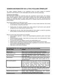
150 (5.91)G_D011_EN_00028135 (5.31)140 (5.51)181 (7.13)G_D011_EN_00031SINAMICS G110Inverter chassis units 0.12 kW to 3 kWControlled Power Modules© Siemens AG 2007■ Dimensional drawings290 (3.54)79 (3.11)116 (4.57)140 (5.51)127 (5.0)142 (5.59)140 (5.51)150 (5.91)160 (6.30)Inverter FSA; 0.12 kW to 0.37 kWInverter FSB; 1.1 kW to 1.5 kW90 (3.54)79 (3.11)131 (5.16)184 (7.24)170 (6.70)152 (5.98)140 (5.51)150 (5.91)G_D011_EN_00029G_D011_EN_00032Inverter FSA; 0.55 kW to 0.75 kW90 (3.54)79 (3.11) 101(4.01)Inverter FSC; 2.2 kW to 3.0 kWWith attached operator panel (BOP), the mounting depth isincreased by 8 mm (0.31 inches).All dimensions in mm (values in brackets are in inches).140 (5.51)G_D011_EN_00030Inverter FSA with flat heat sink; 0.12 kW to 0.75 kW2/10 Siemens D 11.1· 2007
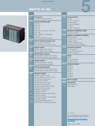
© Siemens AG 2007SINAMICS G110Inverter chassis units 0.12 kW to 3 kWControlled Power Modules■ SchematicsGeneral circuit diagramBasic Operator Panel (accessories)2JOG200 V to 240 V 1 ACPEFS1PEL1, L2/NAnalog variantInput voltage0 V to + 10 V+AIN+9or+10 VAIN+- > 4,7 k89AD100 V10USS variantP+8AACN-9BRS485DCCPUDC -+-24 V- 0 V0 V60HzBusTerminationDC+max. 30 Vmax. 5 mA50HzOFFDIN0DIN1DIN23457orDIN0DIN1DIN234567+24 V (max. 50 mA)DCACDOUT+24 V DC 50 mADOUT-21PEU, V, WG_D011_EN_00027For an additional digital input (DIN 3)external connections should be made:M3 ~DIN3 9DIN39+24 V-0 V7or24 V6Siemens D 11.1· 20072/11
SINAMICS G110Inverter chassis units 0.12 kW to 3 kWStarter kit© Siemens AG 20072■ Overview■ Selection and ordering dataStarter kit0.75 kW, GermanOrder No.6SL3200-0AB10-0AA0The SINAMICS G110 starter kit offers an easy introduction tovariable-speed drives.Available in a stackable transport case, it contains:• Inverter (0.75 kW) with analog input and integrated EMCfilter• BOP operator panel• PC inverter connection kit• Short description, operating instructions, and parameter list(hard copy, in German)• STARTER commissioning tool on CD-ROM incl. operating instructions,parameter list, and Getting Started guide• Screwdriver2/12 Siemens D 11.1· 2007
© Siemens AG 2007SINAMICS G110Inverter chassis units 0.12 kW to 3 kWLine-side power components■ OverviewIntegrated EMC filterVersions with integrated EMC filters class A and class B areavailable for the corresponding environments.• Class AThe requirements are fulfilled when shielded cables with amax. length of 10 m (for FSA) or 25 m (for FSB and FSC) areused. The limits comply with EN 55011 class A.• Class BThe requirements are fulfilled when shielded cables with amax. length of 5 m are used. The limits comply with EN 55011class B.An inverter with an integrated filter can be used with a 30 mA residual-currentcircuit-breaker and is only suitable for installationswith fixed wiring.Inverters without filters, which are used with “filter class B withlow leakage currents”, have a leakage current of < 3.5 mA (up to5 m shielded motor cable).Additional EMC filter, class BAvailable for inverters with an internal EMC filter.With this filter, the inverter complies with the emission standardEN 55011, class B.The requirements are fulfilled using shielded cables with a max.length of 25 m.Filter class B with low leakage currentsWith this filter, the inverter complies with emission standardEN 55011, class B. The leakage currents are reduced to 16 A and ≤ 75 A per phase”, a permissionto operate drives on the public low-voltage network must beobtained from the power supplier. For the harmonic currents, seethe instruction manual.2Siemens D 11.1· 20072/13
SINAMICS G110Inverter chassis units 0.12 kW to 3 kWLine-side power components© Siemens AG 20072■ Selection and ordering dataThe line-side power components listed here must be selected inaccordance with the inverter. EMC filters and line reactors arenot suitable for base-type installation.The inverter and associated line-side power components havethe same rated voltage.OutputFilter class B withlow leakage currentsLine reactorAll line-side power components are certified to UL (with the exceptionof fuses). Fuses of type 3NA3 are recommended forEuropean countries. Further information about the listed fusesand circuit-breakers can be found in Catalogs LV 1 and LV 1 T.UL-listed fuses such as the class NON fuse series fromBussmann are required for North American countries.Additional EMC filter,class BFuseCircuit-breakerskW hp Order No. Order No. Order No. Order No. Order No.Line-side power components for inverters without filter0.12 0.16 6SE6400-2FL01-0AB0 6SE6400-3CC00-4AB3 – 3NA3803 3RV1021-1DA100.25 0.33 6SE6400-2FL01-0AB0 6SE6400-3CC00-4AB3 – 3NA3803 3RV1021-1FA100.37 0.50 6SE6400-2FL01-0AB0 6SE6400-3CC01-0AB3 – 3NA3803 3RV1021-1HA100.55 0.75 6SE6400-2FL01-0AB0 6SE6400-3CC01-0AB3 – 3NA3803 3RV1021-1JA100.75 1.0 6SE6400-2FL01-0AB0 6SE6400-3CC01-0AB3 – 3NA3805 3RV1021-1KA101.1 1.5 6SE6400-2FL02-6BB0 6SE6400-3CC02-6BB3 – 3NA3807 3RV1021-4BA101.5 2.0 6SE6400-2FL02-6BB0 6SE6400-3CC02-6BB3 – 3NA3810 3RV1021-4CA102.2 3.0 6SE6400-2FL02-6BB0 6SE6400-3CC02-6BB3 – 3NA3814 3RV1031-4EA103.0 4.0 – 6SE6400-3CC03-5CB3 – 3NA3820 3RV1031-4FA10Line-side power components for inverters with integrated filter class A/B0.12 0.16 – 6SE6400-3CC00-4AB3 6SE6400-2FS01-0AB0 3NA3803 3RV1021-1DA100.25 0.33 – 6SE6400-3CC00-4AB3 6SE6400-2FS01-0AB0 3NA3803 3RV1021-1FA100.37 0.50 – 6SE6400-3CC01-0AB3 6SE6400-2FS01-0AB0 3NA3803 3RV1021-1HA100.55 0.75 – 6SE6400-3CC01-0AB3 6SE6400-2FS01-0AB0 3NA3803 3RV1021-1JA100.75 1.0 – 6SE6400-3CC01-0AB3 6SE6400-2FS01-0AB0 3NA3805 3RV1021-1KA101.1 1.5 – 6SE6400-3CC02-6BB3 6SE6400-2FS02-6BB0 3NA3807 3RV1021-4BA101.5 2.0 – 6SE6400-3CC02-6BB3 6SE6400-2FS02-6BB0 3NA3810 3RV1021-4CA102.2 3.0 – 6SE6400-3CC02-6BB3 6SE6400-2FS02-6BB0 3NA3814 3RV1031-4EA103.0 4.0 – 6SE6400-3CC03-5CB3 6SE6400-2FS03-5CB0 3NA3820 3RV1031-4FA102/14 Siemens D 11.1· 2007