ecophon focus - Rigips
ecophon focus - Rigips
ecophon focus - Rigips
- No tags were found...

Create successful ePaper yourself
Turn your PDF publications into a flip-book with our unique Google optimized e-Paper software.
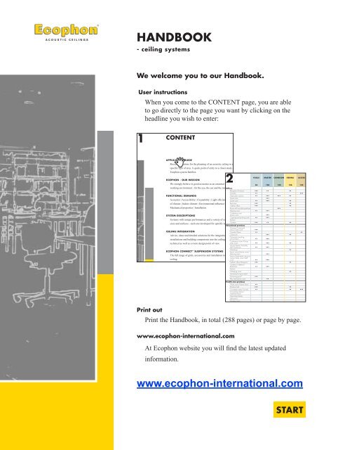
HANDBOOK- ceiling systems
CONTENTAPPLICATION GUIDERecommendations for the planning of an acoustic ceiling in aspecific type of area. A quick point of entry to a closer study ofEcophon system families.4ECOPHON - OUR MISSIONWe strongly believe in good acoustics as an essential part of a goodworking environment - for the eye, the ear and the mind.6FUNCTIONAL DEMANDSAcoustics | Accessibility | Cleanability | Light efficiency | Influenceof climate | Indoor climate | Environmental influence | Fire safety |Mechanical properties | Installation10SYSTEM DESCRIPTIONSSystems with unique performances and a variety of edge designs,sizes and surfaces - each one developed for specific needs and areas.44CEILING INTEGRATIONAdvice, ideas and detailed solutions for the integration of serviceinstallations and building components into the ceiling - from atechnical as well as a room design point of view.204ECOPHON CONNECT SUSPENSION SYSTEMSThe full range of grids, accessories and installation tools for theceiling.234ECOPHON - THE COMPANYMore than 40 years of global experience of the acoustic ceilingsbusiness has given us a genuine knowledge of the importance of agood sound environment as well as of developing, manufacturingand marketing acoustic ceilings.266E-TOOLS AND SPECIFICATIONSEcophon offers several digital tools that will help to speed up andsecure the planning, design and specification of suspended ceilings.You can find these tools at www.<strong>ecophon</strong>.com268OVERVIEWSEdge Design | Colours | Technical data | Acoustics glossary270
ECOPHON FOCUS The most comprehensive system family. It offers flat and curved panels,level changes, unique perimeter details and integrated lighting.46ECOPHON MASTER Provides excellent sound absorption, especially in open-plan offices andlecture rooms, conference halls, etc where easy communication is mostimportant.ECOPHON COMBISON Combines sound insulation and sound absorption in the very samesystems, e.g. for buildings where room divisions have to be flexible.106124ECOPHON GEDINA A dependable standard solution in cases when functional requirements arestrict and design possibilities are limited.136ECOPHON ACCESS Hinged panels with no obstructing cross tees give quick and full accessto services in the void that need frequent inspection, alteration ormaintenance.ECOPHON ADVANTAGE Our budget alternative which still meets the most essential requirements.142152ECOPHON SOMBRA Systems for premises where a really dark ceiling is desired. Offerspossibilities for sound control, e.g. in cinemas.158ECOPHON HYGIENE Combines excellent acoustics and washability properties. Well suitedfor premises in the food industry, the pharmaceutical industry andprofessional kitchens.ECOPHON SUPER G Ceiling systems with high mechanical resistance for areas such as sportshalls and gymnasiums.166188ECOPHON WALL PANEL To be used as an alternative in cases where an acoustic ceiling does not fit,or as a complement in certain rooms or areas.198| 3
APPLICATION GUIDEThis guide is intended to help you find a suitable ceiling solution fora specific type of area. The recommendations are based on our longexperience of meeting the demands and requirements of acoustic ceilingsunder general conditions in selected areas. However, specific conditionscould mean that a system range shown in the chart for a particular areamight not be as suitable as another, which is not shown. It all depends onthe situation. We have decided to present the two best alternatives for eacharea, also indicating that there could be other, lower ranked alternativesamong our systems.In the section for Functional demands you will find detailed descriptionsof the demands and standards for ceilings. For information on theperformance of each system, please refer to the system description. Shouldyou have any special requirements or require further information you arewelcome to contact us.Offi ce building Kv. Farao Solna, Sweden,Architect: Kristian Lindgren Arkitektkontor AB,Photo: Lars Hallén4 |
FOCUS MASTER COMBISON GEDINA ACCESS ADVAN-TAGESOMBRA HYGIENE SUPER G WALLPANEL46 106 124 136 142 152 158 166 188 198OfficesReception/Entrance ••• •• •• •••Corridor •• •••Open plan solution •• ••• ••• •• •••Quiet zone ••• •••Quiet room •• ••• •• •••Rest area ••• ••Cellular offi ce ••• ••Room with movable partitions•••Meeting room •• ••• •••Conference andlecture room ••• •••Copying and printing room •• ••• •• •••Kitchen•••Canteen ••• •• ••Educational premisesEntrance/Communalarea/Cloak room ••• ••Corridor/Stairs •• •• •••Classroom ••• •• •••Open-plan teachingenvironment •• ••• •••Conference room/Groupstudy room •• ••• ••Lecture theatre/Assemblyhall/Auditorium •• ••• •••Workshop •• •••Music room/Drama room/Dancing room ••• •••Library/Multimedia resourcecentre/Study room/Staffroom •• •••Cellular offi ce/Reception ••• ••Canteen/Cafeteria/Restaurant •• •••Kitchen•••Changing room •• •••Gymnasium/sports hall* ••• •••Swimming pool* ••• ••• ••Play and activity room •• ••• ••Health care premisesWard room/Patient Room •• •••Entrance hall ••• ••Circulation area/Corridor •• •• •••Consultation Room/Treatment Room•••Operating theatre•••Laboratory•••Hygiene room•••Waiting room/Library ••• ••Restaurant/Café ••• •• ••Intensive care/Recoveryroom•••Kitchen•••Cellular offi ce ••• ••Offi ce room with movablepartitions•••CinemaEntrance hall ••• ••Movie theatre ••• •••Projector room •• •••Corridor ••• ••Rest room ••• ••Sports and leisureTennis hall ••• ••Sports hall* ••• •••Swimming pool* ••• ••• ••RestaurantsDining room ••• •• ••Kitchen•••CommercialShop ••• ••• ••Shopping mall ••• ••IndustryPharmaceutical•••Food preparation•••Electronic•••••• = recommendation •• = good alternative * = investigation required| 5
6 |
OUR MISSION IS TO CONTRIBUTE TO AGOOD WORKING ENVIRONMENT FORTHE EYE, THE EAR AND THE MIND.It is a well-known fact that our environment in general has an impacton our well-being. But how are we affected by sound? What soundsdo we want to hear? What sounds disturb us? Our business concept isrooted in these simple yet crucial questions.OUR MISSION IS TO CONTRIBUTE TO A GOOD WORKINGENVIRONMENT...Noise and a poor acoustic environment are obviously not the only thingsthat affect our behaviour, our reactions and other events around us.However, there is no doubt that we are affected by these two factors, bothphysically and psychologically. Numerous studies have confirmed this.The idea behind our acoustic ceilings is that they should be an elementof the whole - an interior system, a building system, an experience- where each element influences how we feel. Therefore our aim - ourmission - extends beyond manufacturing and selling suspended ceilingtiles. We want to contribute to interiors that appeal to the eyes, the earsand the entire minds of the people who occupy and work in these varioussurroundings.We are therefore constantly developing solutions that are tailored to suitdifferent purposes and end-users. For example, a school should be plannedfrom the point of view of the pupils and teachers, and a hospital with theobjective of promoting healing and recovery.LEFT:ABOVE:Photo: Elisabeth ZeilonMälardalenshögskola, Sweden,Architect: White Arkitekter,Photo: Åke E:son Lindman| 7
RIGHT:Brabant Mobiel Oosterhout, The Netherlands,Architect: Van Tienen Ontwerpburerau, Terheijden,Photo: Ron Huizer Reclamefotografi e, OosterhoutABOVE:Klinteskolan Gotland, Sweden,Architect: Gunnar Gustafsson, BJ Konsult AB,Photo: Thore Nilsson, Bildvision AB,Visby...FOR THE EYE...In most cases, the suspended ceiling is the largest continuous surface ina room, which means it affects the entire feel of the interior. It is one ofthe surfaces that encloses the room, as well as being an important area inwhich the various service installations are integrated.Sometimes the ceiling contributes as a visual design element,sometimes as a neutral, timeless background. Whatever its role, itsinteraction with the room in general is fundamental. For the ceiling tocontribute to an attractive unified appearance, it must be possible to deviseelegant junctions with walls and services in the ceiling and to make infillseasily.The suspended ceiling also plays an important role in using anddistributing light - incident daylight as well as artificial light....THE EAR...A beautiful interior setting, but with all due respect, what auditoryimpression does it give? Hearing is a sense that never rests. If we shut outdisturbing sounds, we also risk missing what we really want to hear. Notonly loud sounds but also undesirable sounds are major problems today,both for the body and for the mind. A space where we need to concentratefor some tasks and in which we can communicate with other people onother occasions, requires a good, well-designed acoustic environment.Our workplaces have numerous sound sources competing for ourattention. At the same time, we are expected to be efficient and to performwell. However, if we are forced to expend energy on shutting out noiseand other sounds we do not want to hear, there is little left for performingour tasks. And when we are not at work, and wish to relax with familyand friends, our energy may be exhausted. This can result in unnecessarystress and poor health.8 |
...AND THE MINDBeing in a comfortable and safe environment promotes the inner balancewe all strive for. Just imagine the feeling of harmony you experience ona beautiful day in a natural setting or in an environment which has beenperfectly planned, built and equipped to meet your needs.This is the feeling that guides us in our developing work. Ceilingsystems should form part of a good working environment that satisfiespeople’ s minds from a visual, acoustic and physical point of view. Thisshould contribute to people feeling good in spite of the high demands thatare placed on their level of efficiency, productivity and concentration.In addition to the challenges regarding design and acoustics, ourceilings must also meet stringent demands with regard to function invarious technical and practical areas. Their potential for integration andtheir non-visible properties, e.g. influence on the environment and indoorclimate, are factors that also bring peace of mind to the users.EHPT Stockholm, Sweden,Architect: Sheiwiller Svensson Arkitektkontor AB,Photo: Åke E:son LindmanKonkurrensverket (The Swedish Competition Authority)Stockholm, Sweden,Architect: Scheiwiller Svensson Arkitektkontor, Stockholm,Photo: Åke E:son LindmanHöjgaard & Schultz Copenhagen, Denmark,Architect: Dissing+Weitling,Photo: Ole Jais| 9
kgFUNCTIONALDEMANDSThe physical requirements of buildingsand the demands put on them spanmany technical areas and can differconsiderably from one environment toanother as well as between variousapplications. To make buildingsfunction as intended, with user-friendlyenvironments, high demands are placedon the building materials and technicalsolutions used. The functional demandsplaced on ceilings are often considerable.Properties and performance must conformto building standards, regulations andindividual specifications, which take intoconsideration both present and futureactivities in the premises.AcousticsAccessibilityCleanabilityLight effi ciencyInfl uence of climateIndoor climateEnvironmental infl uenceFire safetyMechanical propertiesInstallation12222426283132333841
MUSIC ROOMSLARGE ROOMS FOR COMMUNICATION• Wall-to-wall ceiling• Limited sound absorption inhigher frequencies• Short reverberationtime for good speechintelligibility• Some sound refl ectionmight be needed• Sound absorbers on therear wallIf a classroom is solely used for music, werecommend that the whole ceiling area iscovered with a sound absorbing ceiling systemthat has limited absorption in the higherfrequencies. This will provide greater tonerichness.OPEN PLAN OFFICES• Good sound absorption inall frequencies for limitingthe refl ection of the sound• Effi cient space dividersneeded• Meeting rooms and roomsfor concentration work mustbe availableWhen it comes to minimising sounddisturbance between people in an open planoffice, the layout is very important. Speech isthe most disturbing factor because it is verydifficult to 'tune out'. However, in open planoffices individuals must be given as muchprivacy as possible, for example in caseswhere they are speaking on the phone or witha visitor.In order to prevent sound from beingreflected and propagated via the ceiling, it iscrucial that the acoustic ceiling has excellentsound absorption properties across the wholefrequency range.Good speech intelligibility is highly importantin auditoriums, large teaching rooms,conference rooms etc. This means that a shortreverberation time is required, especially ifa loudspeaker system is used. Useful soundreflections offer a way to improve the clarityof speech far away from the speaker. Oneway of achieving this is to combine absorberswith high sound absorption with more soundreflective ones, ideally those with some lowfrequency absorption.In these larger rooms it is alwaysrecommended to install a wall absorber withhigh sound absorption on the rear wall.SOUND ABSORPTIONA material's sound absorbing properties areexpressed by the sound absorption coefficient,α , (alpha), as a function of the frequency.α ranges from 0 (total reflection) to 1.00 (totalabsorption).ConvertedenergyIncidentenergyTransmitted energyRefl ectedenergyConverted energy+Transmitted energy=Incident energy* absorption coeffi cientWhen a sound wave strikes one of the surfaces of a room,some of the sound energy is refl ected back into the room andsome penetrates the surface. Parts of the sound wave energy areabsorbed by conversion to heat energy in the material, while therest is transmitted through. The level of energy converted to heatenergy depends on the sound absorbing properties of the material.14 |
STI and RASTISTI stands for Speech Transmission Index andRASTI for RApid Speech Transmission Index.They are both measured in similar ways, butSTI covers more frequencies. Consequentlythe figures will be about the same, even if bigdifferences in frequency response can givedeviations. Different figures will howeverbe obtained depending on the volume of theroom.STI and RASTI values vary between 0 and1.00 - where 0 stands for no intelligibilityat all and 1.00 gives total intelligibility. Forexample, in a normal sized classroom, figuresabove 0.75-0.80 would be regarded as good.%-Alcons%-Alcons stands for the percentageArticulation Loss of CONSonants. In otherwords, it takes into account the parts in aspoken word that are most important forunderstanding speech.It is believed that a loss of more than15 % consonants (15 %-Alcons) would bedeemed to be unacceptable for any type ofcommunication. Below 10-5 %-Alcons meansthat the listening conditions are good toexcellent.Signal to noise ratio (S/N)Another important parameter influencingspeech intelligibility is the background noiselevel or, more specifically, the signal to noiseratio (S/N). This is the ratio between signal(e.g. speech) and background noise (e.g.ventilation noise). To achieve good speechintelligibility a signal is considered to be atleast 15 dB above noise level. For hearingimpairedpeople the need is even greater; aratio of at least 20 dB is often referred to.On the other hand, if the signal to noise ratiois much less, or if the signal is lower than thenoise, the signal will be partly masked. Thussome privacy can be achieved.SPEECH PRIVACY BETWEEN WORKING PLACESAccording to the American standard ASTM E1130, speech privacy between working placescan be measured objectively in open planoffices and other environments arranged withan open layout. Such measurements are onlyvalid for their specific configurations and aredependent on certain parameters:• sound absorption effi ciency of the acoustic ceiling and othersurfaces• sound insulation effi ciency of space dividers• layout of working places• background noise level• speech spectrum and levelAccording to ASTM E 1111, acousticsuspended ceilings can be measuredobjectively for their properties in suchapplications. This standard provides themeans to measure the Interzone Attenuationof Ceiling Systems, and the linked standardASTM E 1110 gives the tools to calculate theArticulation Class for classification of ceilingsystems.• STI, RASTI and %-Alcons- methods for measuring andevaluating speech intelligibility.| 17
• A high Articulation Classgives some privacy, a lowerArticulation Class meanslower privacy. Confi dentialconversation and work tasksdemanding concentration needgood privacy.Interzone Attenuation of Ceiling SystemsThe measurement of interzone attenuationdemonstrates the sound reflectivecharacteristics of ceiling systems when used inconjunction with partial-height space dividers.This arrangement is commonly used in officesin order to achieve speech privacy betweenworking places.PlenumLoudspeakerReferencelocation (source)Ceiling test specimenScreenThe measurement set up for interzone attenuation is fi xed with adefi ned layout, a given 1.5 meter high space divider and defi nedpositions for source and receiver. The interzone attenuation iscalculated as the difference in sound pressure level between sourceand receiver for each one-third octave band in the frequency range200-5000 Hz and at each distance.Articulation ClassThe Articulation Class (AC) can be calculatedfrom the interzone attenuation. This can thenbe used as a tool to classify and compareacoustic ceiling systems.The higher the AC the better the speechprivacy in an open plan situation. Werecommend that you use a suspended ceilingwith minimum Articulation class 180 in orderto achieve acceptable speech privacy.SPEECH PRIVACY VALUESArticulation Class200 Master A/alpha, Super G Plus190 Master C, D, E/alpha, Combison Duo A, E,Focus A, Gedina A.180 Focus C, D, DG, E, Gedina EIncreased background noise - not recommendedIncreased background noise can havelong-term negative effects, such as illness,fatigue, decreased productivity and efficiency.Therefore it is not recommended to attemptto obtain better daily speech privacy byincreasing the ventilation noise, or use othersound masking systems.Another thing to bear in mind is that peopleare differently sensitive to sound and noisein general. Privacy and seclusion in openplan spaces can only be solved satisfactoryby creating separate rooms for confidentialdiscussions and work tasks needing higherconcentration.SOUND INSULATIONSound insulation is the ability of a buildingstructure to prevent sound from passingbetween two premises. Two types of soundinsulation will be discussed:• airborne sound insulation• impact (footstep) sound insulationAIRBORNE SOUND INSULATIONWhen airborne sound energy strikes apartitioning structure, some of the soundenergy is reflected by the structure and somepasses through. The structure thus reducesthe sound energy that would otherwise betransmitted to adjacent spaces. The structureis said to have a sound reduction index R (dB),which indicates a particular air-borne soundinsulation.170 Master A/beta160 Combison Solo A, D, E130 Master A/gamma18 |
Good sound absorption in a room also reducesthe sound transmission to the adjacent spaces,as well as the sound level generated in thereceiving room.The sound reduction of a structure dependson the frequency of the sound, the compositionof the structure and how it is connected tosurrounding structures.TEST METHOD AND RESULTSNormally the sound reduction index ismeasured in one-third octave bands accordingto EN ISO 140 or ASTM E 90 and E 1414.For building acoustic applications, the soundreduction index is examined over the 100-3150Hz frequency range in ISO and 125-4000 Hzin ASTM.A weighted sound reduction single valuecan be obtained by weighting the 16 onethirdoctave band values (included in abovefrequency ranges). According to EN ISO 717-1the airborne sound insulation in laboratoryis expressed as R wdB for a wall or floorconstruction and as D n,c,w(dB) for a suspendedceiling system. On site the airborne soundinsulation between two premises is expressedas R' w(dB).For a sub-structure like a suspended ceilingthe improvement is expressed as ∆ R wdB and∆ R' w(dB) respektively.According to ASTM E 413, thecorresponding expressions for wall or floorconstructions are STC dB and CAC dB forsuspended ceiling systems in laboratory. Onsite the airborne sound insulation is expressedas FSTC or NNIC dB.IMPACT SOUND INSULATIONThe impact sound insulation is the reduction ofdefined footstep sound by a floor construction,expressed as the impact sound level L n(dB)in the room below the floor. It is measuredaccording to EN ISO 140 in the same frequencyrange as the air-borne sound insulation andweighted into a single value impact sound levelaccording to EN ISO 717-2. In laboratory theweighted impact sound level is expressed asL n,w(dB) and on site as L' n,w(dB).For a sub-structure like a suspended ceilingthe improvement is expressed as ∆ L n,w(dB)and ∆ L' n,w(dB) respectively.SUSPENDED CEILINGS AND SOUNDINSULATIONA suspended ceiling system can improvesound insulation in several different ways, bothhorizontally and vertically.• Room-to-room sound insulation• One-way sound insulation• Air-borne sound insulation• Impact sound insulationROOM-TO-ROOM INSULATIONIn many cases a continuous suspended ceilingis chosen in order to achieve maximumflexibility. However these constructions willgive lower sound insulation compared toconstructions where the partitions are allowedto penetrate the suspended ceiling or reach allthe way up to the soffit.| 19
If partitions do not reach the structural soffita horizontal transmission path for the soundvia the void over the suspended ceiling iscreated. Therefore, traditional acoustic ceilingsoften provide insufficient sound insulation. Inthese cases special acoustic ceiling systemsare required which offer additional soundinsulating properties.When estimating the airborne sound insulation• consider the whole structure• note that on site values are lower than laboratory valuesLaboratory value/site valueIn practice on site, the room-to-room soundinsulation ( R' w) can be estimated to be 5-8dB lower than the lowest value in laboratoryfor the suspended ceiling and partitionrespectively. This is due to the fact thatinteraction between the suspended ceilingand the partition considerably reduces soundinsulation. Also flanking transmission mightoccur and some installation details might notbe perfect.RecommendationsDifferent transmission paths between rooms.In order to provide reasonable privacy werecommend that normal offices have soundinsulation between adjacent rooms of R' w= 35dB. This requires a suspended ceiling with alaboratory value D n,c,w= 40 dB.The general approach is to combine a soundinsulating suspended ceiling with partitionsthat offer at least the same sound insulationvalue in a laboratory. Other transmission paths,i.e. ventilation systems, should have an evenbetter sound insulation value. The values usedfor the suspended ceiling and the partitionshould also include possible installations intothem, such as lighting and ventilation units ordoors and windows.ROOM-TO-ROOM SOUND INSULATION VALUESLaboratory value D n,c,w40-42 dB Combison Solo/Combison Duo43-45 dB Combison Solo/Combison Duo + Combison XR600 mm on each side of the partitionONE-WAY SOUND INSULATION46-48 dB Combison Solo/Combison Duo + Combison XRall over the suspended ceiling46-54 dB Combison Solo/Combison Duo + CombisonBarrier over the partitionSite result will be 5-8 dB lower than laboratory value.Installations in the void between the structural soffi t and thesuspended ceiling, such as piping and ductwork systems, can giverise to noise. In such cases, a sound insulating suspended ceilingsystem can be used to reduce the noise to acceptable levels in theroom below.20 |
ONE-WAY SOUND INSULATION VALUESIMPACT SOUND INSULATIONLaboratory value R w12-15 dB Master20-25 dB Combison Solo/Combison Duo23-30 dB Combison Solo/Combison Duo+ Combison XRIn order to determine the noise level generated by a source in thevoid, you should ascertain the frequency spectra of the suspendedceiling's sound insulation and the noise source.AIRBORNE SOUND INSULATIONThe airborne sound insulation of a floorstructure can be improved by means of asuspended ceiling system. Airborne soundinsulation may relate to sounds generated inboth the room below and the room above.Improvements are always linked to a specifictype of floor structure.Impact sound insulation relates to thereduction of footstep sound from peoplewalking on a floor structure. It is determinedby the impact sound level in the room below.A suspended ceiling system can be used toimprove the impact sound insulation andtherefore reduce the impact sound level.Improvements are always linked to a specifictype of floor structure.IMPACT SOUND LEVEL VALUESImprovement of laboratory value ∆ L n,w4-7 dB Master7-10 dB Combison Solo/Combison Duo11-14 dB Combison Solo/Combison Duo+ Combison XRThe improvements are linked to a homogenous concrete fl oor of normalthickness (160-200 mm) and with a plastic carpet.AIRBORNE SOUND INSULATION VALUESImprovement of laboratory value ∆ R w5-8 dB Master6-10 dB Combison Solo/Combison Duo10-14 dB Combison Solo/Combison Duo+ Combison XRThe improvements are linked to a homogenous concrete fl oor ofnormal thickness (160-200 mm) and with a plastic carpet.| 21
ACCESSIBILITYAn important function of a suspended ceiling is to conceal plumbing and heating systems,as well as the electrical, telephone and data communications services that are installed inthe ceiling void. Many suspended ceilings will need to be demounted totally or partiallyduring their service life when such services are augmented, maintained or repaired. Also,damaged panels must sometimes be replaced.PLAN FOR MAXIMUM DEMOUNTABILITYThe design of the ceiling tile edges togetherwith the suspension system provides differentdegrees of demountability. The Ecophon rangeoffers ceiling systems with full demountability,even with concealed suspension systems.However, cable management, ventilationequipment, lighting installations and otherfeatures can limit the demountability ofindividual ceiling panels. These problems canbe reduced by carefully planning the ceilinglayout and by following the plans throughoutthe installation. Examples of this can be foundin section ”Integration”.The Connect T15/T24 Cross tees can bedemounted even in the middle of a ceilingarea. This is a great advantage when aninstallation passage is required.ACCESSIBLE SPACE FOR SERVICEFor every system featured in this cataloguethe minimum overall depth of system (o.d.s.)and the minimum depth for demountability(m.d.d.) are given. These measurements arealso denoted ∆ (o.d.s.) and δ (m.d.d.).The o.d.s. is measured, while the figuresfor the required m.d.d. are empiricallyassessed. In practical terms, this means that themeasurements might vary slightly dependingon the skill and experience of the installer.VERTICAL DIMENSIONS∆ = Minimum overall depth of systemδ = Minimum depth for demountabilityThe overall depth of the system (o.d.s.) is the dimension from theunderside of the structural soffi t to the underside of the suspendedceiling.The minimum depth for demountability (m.d.d.) is the dimensionrequired, to fi t and demount individual ceiling panels. It is measuredfrom the underside of the suspended ceiling.FOR FREQUENT ACCESSHinged ceiling panels (Ecophon Access) arerecommended in areas where the servicesabove the ceiling are frequently accessed.These systems provide complete accessibilitywith no obstructing profiles.Inspection panels (Connect Inspectionpanel) are recommended, even in ademountable ceiling, where access to the voidis frequently needed, e.g. under stop valves.NOTE• Clean cotton gloves should always be worn to avoid soiling theceiling during demounting or maintenance work.• Avoid placing panels in the void, since they might be damagedby sharp profi le edges, etc.• Consider how accessible thevoid needs to be.• Concealed grid anddemountability is possible.• A special system is availablewhen frequent access to the voidis needed.22 |
SURVEY OF SYSTEMS ACCESSIBILITY ACCESSIBILITY GUIDEAccessibility Ceiling system Minimum Minimum All available accessibility guides canoverall depth depth forof system, demountability,be downloaded from the homepage ofmmmmour web-site atwww.<strong>ecophon</strong>.com/Easily demountable,completeaccessibilityAccess AAccess CAccess EFrom 120From 130From 130809090EasilydemountableFocus AFocus DFocus DGFocus EFocus EbxMaster AMaster ECombison Solo ACombison Solo DCombison Solo EGedina AGedina EAdvantage AAdvantage ESombra ASombra DSombra E50 -10060-13065-11560-11011050-10070-12050-10013060-11050-10060-11050-10060-11050-15060-13060-110120-13030-5030-55120-160150170-20017012030120100-12090-16010090-11012030110DemountableFocus A XLFocus D XLFocus DG XLFocus E XLFocus S-LineFocus L-LineFocus QuadroMaster DCombison Duo ACombison Duo EHygiene Meditec AHygiene Meditec EHygiene Performance AHygiene Protec AHygiene Advance ASuper G40-10050 -13011550-110---105-14580-10090-1105060150-170150150-170200-25065-10030-753075-110---80220230100110150150150200-250NondemountableFocus BFocus CFocus FFlexiformMaster BMaster CMaster FHygiene Protec CSuper G Plus2323-13520-4343-1554013542-300---------| 23
CLEANABILITYEcophon ceilings can be dusted, vacuum cleaned, wet cleaned or foam cleaned withhigh pressure hosing, depending on actual sound absorber and construction of the ceilingsystem.In order to obtain a long-lasting ceiling with a long service life and economicalmaintenance, the visible surface should be dirt and dust repellent and easy to keep clean.Ecophon panels with Akutex T are a good choice, as they have a coating that preventsdust from adhering. Therefore, they have a high resistance to soiling.• Cleaning properties affectlife-span and economy• Plan for minimum soiling andregular cleaning• Different ceiling systemswithstand different cleaningmethodsHOW TO PREVENT SOILINGVentilation is often responsible for soilingceilings. Regular maintenance of theventilation system is one way of minimisingthis. Generally, a displacement ventilationsystem (a ventilation system with low velocityair supply located at low level) gives lesssoiling than a mixing ventilation system (withthe air supply in the ceiling).Another way to keep the ceiling clean is toavoid pressure differences between the roomand void. Open grilles, perforated shadowlinetrims, open light fittings or similar caneliminate such pressure differences. If there isa pressure difference, the ceiling will act like afilter and might become dirty.It is important that the ceiling can becleaned throughout its service life. Thisapplies particularly to ceiling tiles thatbecome soiled around ventilation components,or when installations in the ceiling void areserviced.To avoid unnecessary soiling it is advisableto always wear clean cotton gloves whenhandling the panels.For the same reason the ceiling should beinstalled as late as possible in the buildingprocess.CLEANING METHODSIf the entire ceiling or parts of it areparticularly subjected to soiling, it is importantto get it regularly cleaned. In this way thecleaning work will be straight forward, ratherthan allowing dirt to build up over long periodsof time. Using clips on the back of the ceilingtiles facilitates cleaning.For more detailed information seeMaintenance instructions at www.<strong>ecophon</strong>.com.DRY CLEANINGDusting should be carried out with a dry, softcloth, a soft brush or similar.Vacuum cleaning must be conducted withreduced suction asfor textiles, curtainsetc.MANUAL WET CLEANINGWet cleaning should be carried out with a softsponge or cloth saturated with a detergentsolution of the same type and concentration asis recommended for use on painted surfaces.After washing, rinseimmediately withclean water. Usecircular movementswith moderatepressure during boththe washing andrinsing of the ceiling surface. Wipe dry with aclean, well wrung-out cloth or sponge so thatthe dirt released into the rinsing water does notdry and leave marks.24 |
HIGH PRESSURE WASHINGIn rooms with a requirement for regularwashing or washing methods such as foamcleaning with high pressure hosing, werecommend EcophonHygiene panelswith Connect C3grid system. TheHygiene systemscan withstandmore frequentand/or extensive cleaning and the ConnectC3 grid system fulfils corrosivity category C3according to ISO 12944-2.The recommended working pressure is 2-4MPa (20-40 bar). Working pressures up to 8MPa can be used, provided that the scatteringangle is at least 30° and the distance betweenthe nozzle and the surface of the ceiling isat least 300 mm. Most effective rinsing isachieved by holding the nozzle at an angle ofabout 45° to the ceiling.RESISTANCE TO WET ABRASIONThere are several methods for testing theresistance of painted surfaces to wet abrasion.Ecophon has used the Gardner machine (asdescribed in ASTM D 2486 and SS 184164)to determine the wet abrasion resistance of thepanel’s surface. The Gardner machine featuresa standardised abrasive brush that is passedover the panel’s surface. The number of cyclesneeded to penetrate the surface is counted andcan be used as way of judging the relativestrength of various painted surfaces.Ecophon Hygiene Meditec, Performance andProtec can withstand more than 400 cycleswithout any damage to the surface by theabrasive brush. Hygiene Advance is unaffectedby the brush.CLEANABILITY OF ECOPHON PRODUCTSDrycleaningManual wetcleaningHigh pressurewashingHygiene Advance Daily Daily 1) , 2) Daily 1) , 2)Hygiene Protec Daily Weekly 1) , 2) Twice a year 1) , 2)Hygiene Performance Daily Weekly 1) Twice a year 1)Hygiene Meditec Daily Weekly 1) NoFocus Daily Weekly NoMaster Daily Weekly NoCombison Daily Weekly NoGedina Daily Weekly NoAccess Daily Weekly NoSuper G Daily Weekly NoWall Panel/Akutex T Daily Weekly NoWall Panel/Super G Daily Weekly NoWall Panel/Colorado Weekly No NoAdvantage Weekly No NoSombra Weekly No No1)Appropriate detergents and disinfectants should be used for thispurpose.2)Hygiene Advance, Protec A and Protec Baffl es are demountable,can be cleaned on all surfaces and can withstand frequenthandling. Hygiene Advance and Protec Baffl es can also withstandhigh pressure hosing on all surfaces.| 25
LIGHT EFFICIENCYLighting can make a huge contribution to the overall look and feel of a room. A key factoris how the ceiling refl ects and diffuses the light. To create a pleasant interior the ceilingshould be the lightest surface in the room - a white ceiling will refl ect more light than adarker one. The lighting itself should not cause glare or surface refl ection. This can beavoided by the installation of indirect lighting.When a ceiling gives good light refl ectance and light diffusion, the need for installedlighting is reduced. This results in improved energy efficiency and a better workingenvironment.• Light coloured ceilings makepleasant interiors• Ceilings with high light refl ectancegive cost-effective lighting• Avoid glare and irritatingrefl ections by using indirectlightingLIGHT REFLECTANCELight reflectance is expressed as a percentageand states how much of the light falling on asurface is reflected back.In order to get the best efficiency, both forincident daylight and lighting, the ceiling’slight reflectance should be high. High lightreflectance also reduces the risk of glare fromlight fittings, because this in turn reducesthe luminance ratio (i.e. the difference inbrightness between the light fittings’ luminoussurfaces and the ceiling). In the case ofdirect lighting the suspended ceiling’s lightreflectance should be at least 70%.With indirect lighting, light reflectanceneeds to be higher, because the level ofillumination in the room then depends largelyon how much light the ceiling surface reflects.For satisfactory indirect lighting, the ceilingsurface requires a light reflectance of at least80%.Ceilings with high light reflectance also leadto cost-effective lighting, particularly whencombined with indirect lighting. The diagramshows, in a situation with 100% uplight, howthe illuminance from a certain luminaire in aroom varies depending on the light reflectanceof the ceiling.ILLUMINANCE FROM A CERTAIN LUMINAIRE IN AROOM WITH 100% UPLIGHTIlluminance (lux)Akutex Twhite 010(84%)Akutex T Akutex Tyellow 364 light grey(81%) 965 (65%)Akutex Tmediumgrey 966(49%)Ceilingsurface (lightrefl ectance)Light reflectance is measured in accordancewith the CIE Publication No. 15.2 (1986).Measurement values are evaluated with CIE10 degree Standard Observer (1964) and CIEStandard Illuminant D65.LIGHT REFLECTANCE OF ECOPHON TILESHigh light refl ectance. (Relates toproducts with white surface fi nish.)Medium light refl ectance. Can beused for indirect lighting to someextent.Limited light effi ciency. Not suitablefor indirect lighting.FocusMasterCombisonGedinaAccessHygiene PerformanceHygiene ProtecHygiene MeditecWall Panel/Akutex TAdvantage/whiteColoured productsSombraHygiene AdvanceSuper GSuper G PlusWall Panel/Super GWall Panel/Colorado26 |
LIGHT DIFFUSIONLight diffusion (how light is spread) cansignificantly decrease dazzle and glarefrom the different surfaces and objects ina room. The more diffusely and evenly thelight is spread the better dazzle and glare areprevented. Light diffusion can be defined asthe ratio of the diffused reflected light to thetotally reflected light. According to DIN 5036measurements, Ecophon´s ceiling tiles in lightcolours provide over 99% light diffusion,which means that practically all reflected lightcan be regarded as diffuse.GLOSSAnother way to describe a surface is tomeasure ”gloss”. This value is always relatedto a certain angle (e.g. 20°, 60° or 85°) anddoes not describe how evenly the reflectedlight is distributed in space. The gloss valueis between 0 and 100, where 70 is high gloss,according to most of the relevant standards,i.e. ISO 2813, ASTM D 523 and DIN 67530.The gloss of the Ecophon tiles is low,
INFLUENCE OF CLIMATEAll kinds of material are affected by the surrounding climate. Ecophon products aredesigned for indoor use. Hence, the key climatic factors for consideration are moisture,heat and microbiological activity.The core material in all Ecophon tiles isglass wool that has been treated to be waterrepellent.Therefore, the material does not takeup water by capillary action and the absorptionof moisture from the air is relatively low.Water that occasionally may penetrate thetiles (e.g. in conjunction with cleaning) driesout quickly thanks to the open structure of theglass wool material.Defl ection of ceiling tiles that are deformed after absorbing moisture.Glass wool is one of the materials most resistant to moisture.Thus, glass wool ceiling tiles are dimensionally stable and stayfl at even in environments with high or varying air humidity.At high relative humidity, there is a seriousrisk of condensation, because of thetemperature difference over the ceiling. At95% RH and 30°C, a temperature drop of only1°C will cause condensation. The presenceof liquid water might have many undesiredeffects, such as stains from water-solublesubstances on the visible surface of the ceiling.There is a physical relationship betweenabsolute humidity, temperature and relativehumidity. The warmer the air, the more watervapour it can hold. In other words - a certainabsolute humidity means a lower relativehumidity at a high temperature than at a low.(See graph).Absolute humidity (g/m 3 )RHAlso Ecophon Connect grids and accessoriesare developed to withstand high humidity.NOTE• Ecophon products should be stored indoors. If, temporarily, theyhave to be stored outdoors, they need to be protected againstmoisture.• If the tiles are to be glued, the temperature must be 15-25°Cduring installation.• The panels do have a thermal resistance. This may infl uencethe temperature and the relative humidity in the room and inthe plenum, and should therefore be considered in the moistureand thermo-technical design. Ventilating the plenum will preventcondensation.Temperature (°C)Relationship between temperature, absolute humidity and relativehumidity.• Moisture, heat andmicrobiological activity affectthe ceiling• Too high relative humidity is notcomfortable for people• Special panels and accessoriesshould be used in aggressiveenvironmentsTEMPERATURE, ABSOLUTE HUMIDITYAND RELATIVE HUMIDITY (RH)The relative air humidity varies depending onthe time of year, temperature and climatic zone.Relative humidity RH, expressed in %, isthe ratio of the actual amount of moisture inthe air to the maximum amount of moisture theair can hold at a given temperature. A relativehumidity of 100% means the air can hold nomore water, i.e. condensation forms, and arelative humidity of 0% indicates there is nomoisture in the air.CEILING DESIGN FOR HUMID AREASIn order to minimise the risk of problems withcorrosion, mould and aesthetic performancein a building, the relative humidity shouldnot exceed 70-80% more than temporarily. Inany case, it is not comfortable for people tobe in environments with any higher relativehumidity than this. In comparison, the averagerelative humidity in a rain forest is 75-90%.28 |
When moisture is increased, as in professionalkitchens, swimming pool facilities, showerareas or food preparation industries, theair humidity can rise substantially andoccasionally reach saturation which meanscondensation forms. The indoor climate insuch rooms should therefore be carefullysurveyed before the ceiling systems areinstalled.Moisturecontentand hence give results that are not reliable.Leading testing institutes, such as SP (SwedishNational Testing and Research Institute) andTNO (Netherlands Organisation for AppliedScientific Research) cannot perform tests withsufficient accuracy at RH>95%.Sorption isothermMOISTURE TESTSMost Ecophon ceiling tiles are tested inaccordance with the methods and instructionsstated in ISO 4611. The majority of thetiles can withstand a permanent relativeair humidity of up to 95% at 30°C withoutwarping, deflecting, sagging or delaminating(see Moisture resistance table for details).Occasionally, for example during temporarydamage to air-conditioning plant, etc., theabove limits for air humidity/temperaturecan be exceeded without deterioration of theproducts or their performance. However, this isonly possible provided the tiles are allowed todry out in between.Ecophon does not present higher valuesthan 95% RH at 30°C due to technical andphysical limitations in the testing methods.The fact is, that if the RH exceeds 95%, themoisture equilibrium is extremely sensitivealso to very small climate variations in thetesting chamber. For each specific material, themoisture content can be shown in a sorptioncurve. The sorption curve is very steep athigh RH, and a hysteresis effect exists. Themoisture content in the material is thereforeunpredictable. Thus, attempts to carry outtests at a relative humidity >95% will fail,as the relative humidity will be unstableHysteresis effectRelative humidity (%)ISO 12944-2 deals with the classificationof the principal environments to which steelstructures are exposed. All Ecophon Connectgrids and accessories can withstand a C2environment according to this standard.The Connect C3 grid system has an extraanti-corrosion protection, which makes theproducts withstand a C3 environment.EXTREME ENVIRONMENTS ANDMICRO-ORGANISMSSustained high temperatures and/or airhumidity or environments with aggressivegases or other substances may affect theceiling systems´ appearance and properties.In cases where regular washing or hosingof the ceiling is necessary specially designedsystems, Ecophon Hygiene, should be used. Inthese environments, and in environments withhigh air humidity grid systems with additionalcorrosion protection, Ecophon Connect C3,should also be installed.| 29
The risk of mould and bacteria is animportant consideration in environments withhigh relative humidity. Ecophon productsthemselves do not serve as a natural breedingmedia for mould and bacteria. By keeping theenvironment of the ceiling clean, and having acontrolled climate below the critical humidityand temperature level, the risk for these microorganismsis reduced considerably.Mould and bacteria need specialgrowing conditionsMOISTURE RESISTANCEMax. permanent* relative air humidity95% at 30°C. Higher air humidity/temperature in conjunction with Hygienecleaning.95% at 30°C* FocusMasterCombison SoloGedinaAdvantageAccessSombraSuper GWall Panel/Akutex T andSuper G75% at 30°C* Combison DuoWall Panel Colorado*The air humidity/temperature can be exceeded temporarily– see under Moisture Tests in this chapter.Moisture Right temperature Growth media= Risk for mould and bacteriaEcophon tiles have been tested formicrobiological growth according to theASTM-standard G 21-96 at SLU (the SwedishUniversity of Agricultural Sciences). Thestandard rates the products in 6 classes 0-5.All tested Ecophon tiles were in class 0, whichmeans that they were unaffected.The Moisture Resistance table shows whichclimate the different products can withstandwithout warping, deflecting or delaminating.Note, however, that micro-organisms can alsobe active in less humid climates.Please note that the Hygiene products havethe same climate limitations as for examplethe Focus and Master products, but theHygiene products can withstand more frequentand extensive cleaning. Also see chapterCleanability.30 |
INDOOR CLIMATEDust and various types of emissions make a huge contribution to the increased incidenceof allergies. This is why there often is a <strong>focus</strong> on good indoor climate in new ormodernised buildings.GOOD INDOOR CLIMATEThe indoor climate has a significant impacton people’s health. A poor climate can oftentrigger allergies and stress related illness. Toachieve a good indoor climate:• avoid the formation of dust and dust-gathering surfaces andmaterials• avoid materials that have undesirable emissions• choose material that can easily be cleaned• choose material providing a good acoustic environment• choose material and lighting that provides a good lightenvironment• air frequently and/or have adapted ventilationTHE INDOOR CLIMATE LABELLINGThe Indoor Climate Labelling (DIM) includestesting for emissions and their decay periods.Measurements are carried out to establishhow long it takes for emissions of ammonia,formaldehyde, VOC (Volatile OrganicCompounds) and particles to decay belowspecified levels. The classes are related todecay within 10, 20 and 30 days. Ecophonproducts that are certified by DIM pass thehighest requirement i.e. they are within the 10days decay level. Included are also odour tests.In Finland, the ”Emission classificationof building material”, run by the BuildingInformation Foundation RTS, places mostEcophon products in the highest class (M1).RECOMMENDATION BY THE SWEDISHASTHMA AND ALLERGY ASSOCIATIONProducts recommended by the Associationhave been assessed to be free from allergens,perfume and irritating substances to a degreethat no known, medically reported cases exist.The assessments are made by the ProductCouncil of the Association (specialists inmedicine, chemistry and technology) and arebased on research results, analyses and theformula for the actual product.CLEAN ROOM CLASSIFICATIONIn some environments, it is necessary tolimit the number of airborn particles. Thiscan be a requirement in the pharmaceutical,electronic and food industries, as in somehospital environments. Two standards forclassifying air cleanliness are US FederalStandard 209E and EN ISO 14644-1. Theclassification systems are exclusively basedon the concentration of airborne particles andthere sizes. The table shows the classes definedand how they approximately corresponde.g. ISO class 4 lies between M2 and M 2.5.Included also are the zone classes defined inthe guide ”Good manufacturing practice formedicinal products” issued by the EuropeanCommission.ISO14644-1ISO Class 1ISO Class 2ISO Class 3ISO Class 4ISO Class 5ISO Class 6ISO Class 7ISO Class 8ISO Class 9US FS209 EM 1M 1.5 (1)M 2M 2.5 (10)M 3M 3.5(100)M 4M 4.5(1 000)M 5M 5.5(10 000)M 6M 6.5(100 000)M 7EU/GMPA and BExamples of activities/environmentsZones unoccupiedby personnelTransplantation surgeryManufacturing of highperformance opticalinstrumentsVarious tests and practical experience showthat the Ecophon Hygiene systems can be usedin room classified as M 2.5. For informationregarding other Ecophon systems - seerelevant system description.CDFood and drink industry• Indoor Climate Label• Finnish emission classifi cation• Swedish Asthma & AllergyAssociation• Clean Room Classifi cations| 31
ENVIRONMENTAL INFLUENCEAdministration of the earth’s resources is one of the most important environmental issuesfor the future. This calls for environmental consciousness, knowledge and a desire to worktowards improvement. Therefore, environmental concern should be at the forefront of alldecision-making.310007GLASS AND GLASSWOOL IN THEECOLOGICAL CYCLEGlasswool consists almost entirely of glass.Over 70% of the basic material in Ecophonsound absorbers consist of recoveredhousehold glass and recycled glasswool. Theremaining parts are normally produced fromglass that is made from raw materials such assand and sodium. Glasswool production wastecan be recycled by two unique methods: theOxymelt and the Contiroll processes.CONNECT GRID AND ACCESSORIESIN THE ECOLOGICAL CYCLEConnect grids are manufactured fromgalvanised steel that consists of approximately50% recycled steel. This means that the gridscan be recycled all over again.In the production all steel waste is takencare of local contractors for recyclingTRANSPORT AND INSTALLATIONDue to consistent development work, Ecophonhas been able to decrease the average thicknessof its acoustic tiles, while maintaining theirexcellent properties. This has lead to areduction in volumes, resulting in less energyconsumption during transportation.Another advantage of this decreased volumeis that the tiles are easier to handle, and withtheir low weight, easier for ceiling installersto use.LIFE-SPANThe technical life span for Ecophonceiling systems is the same as that of thebuilding. The practical life span, however,is usually about 20 years, due to changesin fashion, abnormal soiling and/or poormaintenance.THE NORDIC “SWAN” ECO-LABELThe Nordic ”Swan” Eco-label, signifies thatthe product satisfies the Nordic EnvironmentalLabelling Board criteria and requirements overthe whole life cycle. This standard covers boththe external and internal environment and theproduct’s manufacture all the way from theraw materials to recycling. Listed below aresome examples from the criteria document:• have none or in some cases minimum content of substancesharmful to the environment or health• have a high recyclable content• require low energy consumption during manufacture• meet general requirements for low environmental impact onwater, soil and airECOLOGICAL LABELLINGThe Nordic Swan (Licence no 310 007)FocusMasterCombisonGedinaAccessAdvantageSombraHygieneSuper GWall Panel••••••••For detailed information see section System Description• Recycling• Transportation• Ergonomics• Life-span32 |
FIRE SAFETYA fire in a building can develop very quickly and lead to devastating consequences. Inthe design process of a building and when selecting building materials it is therefore ofgreatest importance that the fire safety aspects are treated carefully and with knowledge.REQUIREMENTS ON SUSPENDEDCEILINGSThe fire safety demands on suspended ceilingscan vary depending on both the type of roomand building where they are to be installed.Detailed requirements can be found in thenational building regulations. Three generalrequirements can, however, be identified ascrucial for suspended ceilings in the earlystages of fire. The first two should be regardedas ”compulsory” in all premises, while thethird is normally only required when theceiling void contains relatively large amountsof combustible materials, e.g. cables.FIRE SAFETY IN BUILDINGSThe main purpose of the fire safety design of abuilding is to minimise the consequences of afire. Principally, it concerns the prevention ofinjury to people but it also entails limiting thematerial and economic damage which is likelyto ensue.80°C• They must only make a negligible contributionto the fire development and to the productionof smoke. This is fulfilled by using a ceilingconsisting of materials and surface liningscomplying with at least Euroclass B-s1, d0.• They must not break and collapse during theearly stages of the fire when evacuation andrescue operations can still be carried out.To pass this requirement a ceiling systemshould be able to withstand a heat exposureof approx. 300°C. (The heat radiation from asmoke gas layer with a temperature of 300°Ccorresponds approximately to what a fullyequipped fire fighter can withstand.)• They should prevent ignition of combustiblematerial in the ceiling void in order to delayor prevent the occurrence of flash over. Thisrequirement, as well as the second, is met withceiling systems classified as class K 110/K 210or as ”Fire protection covering” according toNT Fire 003.In a burning building the circumstances can quickly become suchthat there is imminent risk of personal injury. Within the parametersof safe evacuation, consideration must be given to fi re gases,visibility, heat radiation and temperature. E.g. in order to evacuatesafely, the air temperature in rooms through which people areescaping should not exceed approx. 80°C.The total fire protection of a building andits specific function is a complex issue,comprising several areas and how they interactwith one another:• The building itself including its design, building elements,materials, interior fi ttings and furnishing• The fi re detection systems and alarms• The organisation and practice of conducting evacuation, e.g. inschools and nursing homes• The rescue efforts of fi re brigades• The extinguishing and control of the fi re. Partly through automaticfi re extinguishing systems and/or partly through active actions,e.g. of the fi re brigadeBuilding regulations and various types ofstandards normally cover these aspects.The building regulations are formulated ona national basis and vary between differentcountries. Standards can be on either anational base (e.g. DIN, BS and ASTM) orinternational (EN- and ISO-standards).• The surface linings of walls andceiling are crucial for the earlydeveloment of a room fi re• Flash over occurs at atemperature of about 600°C• The maximum air temperature forsafe evacuation is appr. 80°C| 33
At the point of fl ashover the entireroom is engulfed by the fi re andlarge fl ames burst out from door andwindow openings. The fi re can nowspread to other parts of the building.DESCRIPTION OF A FIREWITHIN A ROOMA room fire can be divided into various phases.The incipient phase or beginning of a fire isdependent on the size of the ignition sourceand the properties of the materials and objectsthat are directly affected.During the growth phase the fire increasesin size and other objects around the fire originwill begin to burn. Even the surface linings ofthe walls, floor and ceiling close to the fire canignite. Increasing amounts of smoke and heatbegin to develop and a layer of hot fire gasesforms beneath the ceiling.In the growth phase the fi re is local. The fi re characteristics of thesurface linings play an important part in the fi re development.During the growth phase flashover can occur.This is when the intensity of the fire is so greatthat it ceases to remain local but involves allcombustible material in the room. A largeamount of heat is released and flames burst outthrough windows and door openings.Generally, flashover occurs once the firegases in the room reach 500-600°C. The heatradiation from the layer of fire gases is sogreat at this stage that it causes all combustiblematerials to ignite.Flashover can occur just a few minutes afterignition. However, it can also be delayed oravoided altogether. This could be the casein a room which has just a small amount ofcombustible furnishings and is equipped withsurface linings that make just a negligiblecontribution to the fire development.After flashover the fire reaches its maximumlevel and is fully developed. The length andintensity of the fire is now mainly determinedby the supply of air and the fire load, i.e. theamount of combustible materials present.The decay phase is when the fire fades out.TESTING AND CLASSIFICATION OFPRODUCTSFire testing methods are generally designedto simulate the different phases of the fireprocess. Consequently, tests on surface liningsare conducted using fire sources representativeof the incipient and growth phases of a fire.These test methods are referred to as ”reactionto fire” tests and the purpose is to evalutate thecontribution of products and materials to theearly stages of a fire in terms of:• Ignitability• Flame spread• Heat release• Smoke production• Occurrence of fl aming droplets/particlesNormally reaction to fire tests are carried outin small or intermediate scale.Complete building elements (doors, floorstructures, partitions etc.) which are used forseparating fire compartments are tested forthe case of a fully developed fire. These testmethods are called ”fire resistance” and arecarried out in full scale. The temperature in34 |
the test furnace follows the so-called ”standardfire curve” which is designed to represent afully developed fire. The properties that areevaluated are:• Insulation (ability to reduce the heat transfer)• Integrity (ability to prevent leakage of fl ames and hot gases)• Load bearing capacityBuilding elements classified as ”fire resistant”with respect to integrity and insulation areused as a means to prevent fire being spreadbetween fire compartments.THE EUROPEAN SYSTEMREACTION TO FIRE - EUROCLASSThe new reaction to fire testing andclassification system for linings and materialsin Europe is called Euroclass.Altogether there are 39 classes divided into7 main levels; A1, A2, B, C, D, E and F whereA1 is the best and F are for products andmaterials not classified.Most of the main classes also include anadditional classification regarding smokeproduction and the occurrence of flamingdroplets/particles.The classes for smoke are s1, s2 and s3,where s1 is the best.The classes for flaming droplets andparticles are d0, d1 and d2, where d0 is thebest.A2- s1,Main classSmokeproduktiond0Occurence offl aming droplets/particlesEUROCLASSESTemperatureA1A2-s1,d0 A2-s1,d1 A2-s1,d2A2-s2,d0 A2-s2,d1 A2-s2,d2A2-s3,d0 A2-s3,d1 A2-s3,d2B-s1,d0 B-s1,d1 B-s1,d2B-s2,d0 B-s2,d1 B-s2,d2B-s3,d0 B-s3,d1 B-s3,d2C-s1,d0 C-s1,d1 C-s1,d2C-s2,d0 C-s2,d1 C-s2,d2C-s3,d0 C-s3,d1 C-s3,d2D-s1,d0 D-s1,d1 D-s1,d2D-s2,d0 D-s2,d1 D-s2,d2D-s3,d0 D-s3,d1 D-s3,d2EE-d2FEuroclasses according to classifi cation standard EN 13501-1 Fireclassifi cation of construction products and building elements - Part 1Classifi cation using test data from reaction to fi re tests.Flash overIncipient Growth Fully developed DecayEuroclasses andclass K 210Fire resistance classesTimeThe graph shows the relationship between fi re process and thefi re classesFIRE PROTECTION ABILITY - CLASS KThe information regarding class K reflectsthe situation of March 2003 when theworking process with the European test andclassification standard still was under progress.Changes may therefore have occurred.Class K comprises four classes: K 110, K 210,K 230 and K 260.Class K 110/K 210 derives from andcorresponds mainly to the Nordic testing andclassification standard NT Fire 003 ”Fireprotection ability - Coverings”. This class wasdeveloped and designed for evaluating thefire protection ability of coverings, such assuspended ceilings, in the growth phase of afire.| 35
The main reason for using a ceiling classifiedas K 110/K 210 is that it should prolong thetime to flash over or even prevent it. This isachieved by not allowing any combustiblematerial behind the covering, e.g. cablesand timber members in a ceiling void, tocome into contact with the fire and thereforecontribute to its growth. This means that thefire development will only be governed by theconditions of the room itself.The class also means that the ceiling, orparts of it, does not break and collapse duringthe time evacuation and rescue operations canbe carried out.If there is a need of extending the protectionfunction over the flash over point into thephase of a fully developed fire class K 230 andK 260 could be used.Contrary to the Euroclasses, class Kincludes the complete ceiling system i.e.panels, suspension hangers, fixings, perimetertrims etc. The Euroclass system is onlyconcerned with the panels of a ceiling system,provided that the grid and other componentsdo not contribute to the fire development, e.g.if they are made of metal.Class K 2Load Integrity Insulation Time class10The main classes used for the fire resistanceclassification of building elements are:R = Load bearing capacityE = Integrity (ability to prevent leakage of fl ames and hot gases)I = Insulation (ability to reduce the heat transfer)The classes are always combined with a timecould be from 15 up to 360 minutes in stepsdefined in the classification standard EN13501-2. A separating and load bearing wallcould for example be classified as REI 60,capacity as well as its fire separating functionduring 60 minutes of a fully developed fire.A non-load bearing element will only bea time class. The latter case is for examplewill prevent the penetration of flames and hotgases but not provide insulation against heat.a separating element, can, accordingly, onlya time class.R E I 60From Norwegian/Danish ”Kledning/beklaedning”(covering)Number ofminutes of fi retest.FIRE RESISTANCEclass expressed in minutes. These time classeswhich means that it will retain its load bearinggiven the classification EI or E combined withrelevant for special fire glazed partitions whichA load bearing column, which is obviously nothave the fire resistance class R combined withbearingcapacity(ability topreventleakage offl ames andhot gases)(ability toreducethe heattransfer)10 minutes represents the early stage of fi re. The fi re gastemperature in the test furnace reaches appr. 680°C which is overthe critical temperature for fl ash over.THE ASTM SYSTEMREACTION TO FIREIn the US market products are tested andclassified according to ASTM standards(American Society for Testing and Materials).Flame spread and smoke production ofsurface linings, for example on ceilings, are36 |
tested and evaluated according to ASTM E 84”Surface Burning Characteristics of BuildingMaterials”. A smoke production index andflame spread index is then derived from themeasurements that are taken.Acoustic ceiling products are classifiedaccording to ASTM E 1264. Three fire classesare defined; A, B and C. The classes areequivalent to classes I, II and III, respectively,of various building code authorities. Class A(I) is the best.ASTM fi re classes. In addition, for class A ceiling products thematerial should not show evidence of continuos progressivecombustion after the test fl ame has been extinguished.FIRE RESISTANCEMax allowed indexclass Flame spread Smoke developmentA 25 50B 75 -C 200 -Fire separating elements, such as fire wallsand floor structures, are tested and evaluatedin accordance with ASTM E 119 ”Fire Testsof Building Construction and Materials”.The tests are carried out in full scale. The testspecimens are subjected to a heat exposure thatcorresponds to a fully developed fire.THE SUSPENDED CEILING AS FIREPROTECTION IN PRACTICEClass K 110/K 210 (Fire protection covering)and Euroclass classifications play a crucialrole in the early development of fire andconsequently for the fire safety of a buildingas a whole. In order to obtain the requiredfunctions the assembly instructions and otherconditions included in the classification mustbe followed at the building site.Class K 110/K 210 is a classification, which,unlike the surface lining classifications,encompasses the complete structure, i.e.panels, grid, suspension hangers, fixingsand other included components. None of thecomponents incorporated in the ceiling systemmay be changed in any way without riskingthe validation of the classification.Even if the surface lining classifications arenot as tightly bound as class K 110/K 210 tothe constructional design of the ceiling, thereare still limitations. For example, any kindof repainting or alteration of the surface willmake the classification of the surface lininginvalid. Furthermore, repainting will also havean effect on other properties, such as soundabsorption.REACTION TO FIRE CLASSIFICATIONSUK BS 476 part 6 & 7EUROPE EN 13501-1FR NFP 92-501/510FDP 92-507DE DIN 4102 part 2US ASTM E 1264NL NEN 6065/6066ClassProductsClassProductsClassProductsClassProductsClassProductsClassProductsClass 0FocusGedinaAdvantageSombraMasterCombisonAccessSuper GHygieneWall PanelA2-s1, d0FocusGedinaAdvantageSombraMasterCombison DuoAccessSuper GHygieneWall PanelClassementM0ClassementFocusGedinaAdvantageSombraMasterAccessSuper GHygieneWall PanelFocus S-lineNichtbrennbarA2Schwerentflammbar B1FocusGedinaSombraMasterCombison DuoSuper GWall PanelFocus S-lineFocus QuadroFocus FlexiformClass AFocusGedinaAdvantageSombraMasterCombison SoloAccessSuper GHygieneWall PanelKlasse 1FocusGedinaAdvantageSombraMasterCombison SoloAccessSuper GHygieneWall PanelB-s1, d0Focus S-lineM1Focus QuadroAdvantageFocus QuadroFocus L-lineHygieneFocus L-lineCombisonFocus FlexiformHygiene AdvanceCombison Solo| 37
kgMECHANICAL PROPERTIESMechanical properties embrace load bearing capacity and impact resistance.The tilesand grid of a ceiling system are subjected to different loads. All of these possible loadsmust be considered during the process of planning and designing a ceiling.LOAD BEARING CAPACITY -GRID SYSTEMThe live load - both static and dynamic - towhich the suspension system can be subjected,depends on the demands made on breakageand deformation. In such cases deformationcan be a form of deflection or twisting.DEFLECTION OF GRIDWhen the maximum allowable load ofEcophon ceiling systems is establishedand determined, it is always deflection, notbreakage, that is the decisive factor.A suspended T-profi le exposed with load (F) giving a defl ection (f).VOCABULARY - LOADSStatic loadThe weight of the ceiling itselfand the weights of items attachedto the ceiling e.g. light fi ttings,loudspeakers, ventilation grills, signsand so on.Dynamic loadMechanical impacts, for examplecontact from balls in gymnasiums orwater pressure when the ceiling isbeing cleaned with high pressurehoses.Own weight (g)The weight of the ceiling systemitself (including the tiles, the totalsuspension system and all mountingdetails). This is always a static load.A form of deformation: Twisted profi leBREAKAGEIt is imperative to prevent a ceiling frombreakage or collapsing because it has beenoverloaded. Therefore the recommendedmaximum allowable load for each ceilingsystem (see the installation diagrams) iscalculated and determined with a multiplesafety margin against any kind of failure.Maximum allowable load can only beapplied if the ceiling is complete and has beeninstalled in accordance with the installationdiagram. In other words, the prescribedproducts must be used and all the ceiling tilesmust be in place in the grid.While the grid profiles and hangersconstitute the load bearing capacity andstrength of the ceiling, the ceiling tiles playan important role in stabilising the profilessideways. This is especially important whena profile is loaded eccentrically, which oftenforces it to twist. In light of this, centricloading is always preferable. For example,it is important to install light fittings andother additional components so that the liveload will be transferred centrically into theT-profiles.A load on a profile will always causedeflection (f). The deflection is proportional tothe load and strongly depends of the span (L)between the supports. If the load (F) doubles,the deflection will double. The deflectionbecomes, however, even bigger if the distancebetween two supports doubles. The deflectionfrom a point load will, for example, becomeeight times bigger.In the table below, with recommendationsfor Connect suspension systems and maximumpermitted loading of live load, we have takeninto account the most important standards:ASTM C635, BS 8290 part 2, DIN 18 168and SS 81 51 13. The decisive factor has beenthat deformation should be limited to L/500.When the deflection reaches around L/400it is possible for the human eye to notice thedeformation. The limit L/500 gives, withsafety, a ceiling with a smooth appearance.E x a m p l e : For the span L=1200 mm theallowed deflection is 2,4 mm.38 |
kgRECOMMENDED LIVE LOADThe recommendations apply to live loadin addition to the suspended ceiling’s ownweight. The live load can be point loads (lightfittings, signs etc) located arbitrarily on thesuspension system, but separated by at least 1m. With hangers located more closely together,higher permissible live load than stated in thetable can be achieved. Heavier loads must,however, be hung directly from the soffit.If an actual live load is distributed overan area of 0.36 m² (600x600, 1200x300)or more, the grid is able to take a load 65%bigger than the recommended maximum liveload regarding deformation in the table. Thisis provided the live load is fixed to the gridsystem. The actual live load must, of course,be considered for hangers and fixings.E x a m p l e : A recessed light fitting,600x600 mm, with a weight of 7 kg isacceptable in a Focus ceiling which, accordingto the table, are able to carry a maximum liveload of 83 N (8,3 kg) if the distributed area is0,36 m² or more.Recommended loadEcophon ceiling systemaccording to relevantinstallation diagramFocus, Gedina,Advantage, Sombra,Hygiene 20mm,Meditec, Super G PlusFocus XL1600 incorridors, Master, SuperG, Hygiene 40 mmFocus XL 1800 incorridors, CombisonSoloFocus XL 2000 incorridorsRecommendedmaximum liveload regardingdeformation(point load(F) with 1 mseparation)50 N(5 kg)40 N(4 kg)20 N(2 kg)10 N(1 kg)Recommendedmaximum live loaddistributed on a biggerarea than 0.36 m 2 ,regarding deformation(uniformly distributedloads (q) with 1 mseparation)83 N(8,3 kg)66 N(6,6 kg)33 N(3,3 kg)16 N(1,6 kg)The above applies provided that the distancefrom the joint between two main runners to thenearest support point does not exceed ¼ of theallowable distance between suspensions.The joint to nearest support point should not exceed ¼ of thedistance between two suspensions.This means that, when the distance betweenthe suspensions are 1200 mm, the couplingpoint between two main runners has to beless than 300 mm from the support point. Theabove applies provided that the load will betransferred centric to the T-profile.LOAD BEARING CAPACITY– SUSPENSIONS AND FIXINGSThe chosen suspensions and fixings, such ashangers, direct fixing brackets, screws etc.must be able to carry the design load (theown weight of the suspended ceiling andactual live load) with at least factor three ofthe safety limit set against breaking. Thismeans that suspensions and fixings used tosupport a ceiling must be able to carry, withoutcollapsing, a load at least three times the loadthat they will be imposed to. All Connectadjustable hangers and direct fixing bracketsmeet these demands, providing the installationis carried out according to Ecophon installationdiagrams and the maximum live load for theceiling system has been respected.Suspended T-profi le with differentloads.VOCABULARY - LOADSLive loadAll loads added to the ”naked”ceiling system. Live loads can bestatic or dynamic and embrace:• Uniformly distributedload (q) from light fi ttings,signs, pressure differences,cleaning, etc.• Point load (F) from lightfi ttings, signs, impact, cleaning,etc.• Normal force (N) Forcecaused by impact, abrasion,cleaning and/or installationwork. A dynamic load.Design loadThe own weight of the suspendedceiling and the actual live loads theceiling is designed for.| 39
kgThe load bearing capacity (maximumallowable load) for Connect suspensionand fixing products can be found in sectionConnect grid and accessories. The maximumallowable live load and the required minimumload bearing capacity of the fixings and thehangers for each individual ceiling system canbe found in the installation diagrams.E x a m p l e : For Ecophon Master A themaximum allowable live load is 40 N (4 kg).The minimum load bearing capacity for thehangers and fixings must not be less than 160N (16 kg), included a safety margin of at leastthree against breaking.LOAD BEARING CAPACITY – ABSORBERSThe basic rule is that loads must not beimposed on the absorbers. Light fittings,ventilation components etc. located in thesuspended ceiling should be supported by thesuspension system or be hung directly fromthe soffit.The loading on the tile must bedistributed evenly around the rimof the aperture.However, Ecophon absorbers in 600x600 mmand 1200x600 mm sizes can take small loads,such as halogen spotlights. For absorbers thatare 20 mm or thicker, e.g. Focus or Master,a maximum of 500 g applies, with a largestaperture diameter of 100 mm. The equivalentfor 15 mm absorbers, e.g. Gedina, is 300 g.Tiles wider than 600 mm and longer than1200 mm must not be subjected to loads.DYNAMIC LOAD BEARINGCAPACITY - IMPACT RESISTANCEDynamic load bearing capacity is ameasurement of how well a product or asystem handles dynamic live load, e.g.abrasion or impact. The need for suchresistance to mechanical action differs indifferent environments. The dynamic live loadcan be a separate blow from a ball or a stick.It can also be recurrent, for example an objectthat is being pushed forwards and backwardsalong a surface for a long time. Anotherdynamic live load is the pressure differencethat may occur in a room because of opendoors or the ventilation system.There are different, generally accepted,methods for testing and evaluating the impactresistance of ceiling systems. Ecophon usesthe Ballwurfsicherheit-method according toDIN 18 032, part 3 and an internal test method.Both test methods are based on allowing ahandball to hit the system, after which itsimpact resistance is judged visually.In rooms where the ceiling might besubjected to impact, we recommend EcophonSuper G systems. If no extra protection againsthard or sharp objects has been installed, theacoustic system should be placed away fromthe occupied zone and well out of normalreach. For further advice regarding this, pleasecontact Ecophon.40 |
INSTALLATIONA well-installed ceiling system can really contribute to the overall look and feel of a room.This can be attained by combining Ecophon absorbers with the Connect grid system.Both are simple to handle and install, and together will create a well-fitted ceiling system.HANDLINGThe Ecophon ceiling system is lightweightand therefore extremely undemandingin terms of transportation, handling andinstallation. The structure of glass wool issuch that the tiles have excellent mechanicalproperties relative to their weight. This meansthat Ecophon sound absorbers are stable andcan withstand handling, but are nonethelesspliable and very easy to work with.Of course,the panels canwithstand normalhandling duringinstallation,but due careshould be takento avoid breakingor damaging the edges and surface.It is worth bearing in mind that ceilingproducts are visible parts of the interior andshould be regarded as part of the furniture.Cartons containing panels and grids must behandled according to the instructions on thelabels, such as ’Handle with Care’, ’This SideUp’, and so on. The cartons must be protectedagainst rain and moisture and therefore shouldnot be stored outside.All available installationguides can be downloadedfrom www.<strong>ecophon</strong>.com.Glass wool is very easy to work with in that itis flexible and does not crumble. This meansthat you can easily cut perimeter tiles orholes for pipe-work and cables using just anordinary craftknife. If edgescut on site needpainting, a specialedge sealant isavailable.For aesthetic reasons perimeter tiles should be at least 300 mmwide and lengthening pieces of profi les and angle trims etc. at least400 mm long.CEILING ASSEMBLYSuspended ceilings should always be installedas late as possible in the building processin order to avoid soiling the panels. MostEcophon ceiling panels will come with aninstallation guide for the system you havechosen. The system pages in this catalogueinclude a single installation drawing whichprovides an overview of each system.The Connect grid system, made fromgalvanised steel, is also easy to work with. Apair of metal scissors is all you need to cut theprofiles.In small rooms, such as toilets, pressureshocks can occur when opening and closingthe door, making the tiles lift from theirposition in the grid. This can be avoided byusing open grilles and hold down clips or otherarrangements.• Install the ceiling late in thebuilding process to avoidsoiling it• Always use clean cotton gloveswhen handling ceiling panels| 41
MAINTENANCEClean cotton gloves should be worn at alltimes, both during ceiling assembly andthroughout all work in the suspended ceiling,e.g. installation of light fittings and servicingof ventilation systems. When the panels aredemounted they must be taken completely outof the grid and stored on a flat surface. Thepanels should be laid face to face to preventsoiling and damage during the work.For more information, see thedetailed Maintenance instructions onwww.<strong>ecophon</strong>.com/Inspection panels for ceilings with non-demountable tiles or whenfrequent access is neededLight fi tting clips for installation of uplights, signs, etc.For more information regarding installationtools and accessories see section Connect.TOOLS AND ACCESSORIESIn order to secure a good ceiling system itis imperative that you use well designedinstallation tools and accessories. TheConnect product range offers a vast numberof accessories for a variety of different needs.Below are some examples of the installationtools and accessories offered by Ecophon:A uniquely designed laser tool for securing a perpendicular gridsystemEdge tools for creating edges on perimeter tiles42 |
| 43
AKUTEX T – A UNIQUESURFACE COATINGMost Ecophon sound absorbershave the unique Akutex T surfacecoating.The microporous Akutex Tsurface allows almost 100 percentof the sound waves to penetrateinto the glass wool core and beabsorbed by it. The microscopicpores, however, are much too smallto admit dust and dirt, so from acleaning point of view the surface istight and smooth, dirt-repellant andeasy to clean.Akutex T produces a surfacestructure with very high lightrefl ectance for both incident daylightand that from lighting systems.Moreover, the light is refl ectedvery diffusely and evenly, so itcauses no dazzle or glare. Thisis very important in ensuring lighteffi ciency where indirect lighting isconcerned.
SYSTEMDESCRIPTIONSThe Ecophon range comprises varioussystem families. All of these families havea number of systems which fulfil differentdemands with regard to performancecharacteristics, edge designs, sizes andsurfaces. Each system family has its ownspecific features and has been developedto be ideal for particular areas, althoughthey can be suitable also in othersituations.FocusMasterCombisonGedinaAccessAdvantageSombraHygieneSuper GWall Panels46106124136142152158166188198
Focus DG:Millimeter Arkitekter AB Stockholm,Sweden,Architect: Millimeter Arkitekter AB,Photo: Åke E:son Lindman46 |
Focus D:Brothers Växjö, Sweden,Architect: Brothers & Ecophon,Photo: Johan Kalén| 47
48 |
ECOPHON FOCUS Meets the strictest demands of form and functionFOCUSThe Ecophon Focus family provides comprehensive tools to create a widevariety of ceiling designs - and still meet the strict requirements for firstclassacoustics. An extensive range of edge designs, forms and levels givesyou the freedom to create an environment that attains high standards insound, light, comfort and ambience.EIGHT EDGE DESIGNS FOR APPEARANCE AND FUNCTIONALITYThe systems are available with a variety of edge designs for concealedor visible grid or for direct fixing. Not only will the edge design affectthe overall appearance of the ceiling, but they will enable you to meetdifferent requirements for demountability and access to installations in theceiling void.LEFT:ABOVE:Centre des Arts d Énghien Les Bains, France,Architect: Cabinet Architectoria,Photo: Patrick SalaünHøjgaard & Schultz, Copenhagen, Denmark,Architect: Dissing + Weitling,Photo: Ole JaisFOCUS AVisible grid. Easily demountabletiles.54FOCUS BFOCUS CFOCUS DFOCUS DGFOCUS EFOCUS EBXFOCUS FFor direct fi xing with glue.Concealed grid. Non demountabletiles.Concealed grid. Easilydemountable tiles.Unique edge design. Floatingappearance. Easily demountabletiles.Recessed visible grid. Easilydemountable tiles.Visible grid of box type with fl ushappearence. Easily demountabletiles.For direct fi xing with screws.58606470747880| 49
50 |
ECOPHON FOCUS Unique additional systemsFOCUSThe Ecophon Focus range provides a number of additional systems thatpresent new design and functional possibilities to enhance or complete theacoustic ceiling.ECOPHON FOCUS WINGEcophon Focus Wing provides a whole new dimension to the acousticceiling. With this additional system, the ceiling becomes more than just asurface – it becomes a design element and a focal point. Focus Wing canbe used as a free-hanging unit over a meeting place or a workstation. Itcan also be used for level changes or in transitions to other constructionelements.FOCUS 3-DIMENSIONAL CEILINGSEcophon Focus S-line, Focus Quadro, Focus L-line and Focus Flexiformcurved ceiling panels enable you to vary the heights of different parts ofthe ceiling. They provide an easy way to adapt the ceiling to installationsand the structural features that are inherent to the building. Raising andlowering the ceiling in this way can produce an innovative and excitingceiling design.LEFT:ABOVE:Metro Arkitekter Malmö, Sweden,Architect: Metro Arkitekter,Photo: Johan KalénProject Community Sports Hall Warszawa, Polen,Architect: Przedsiębiorstwo Projektowo-Wykonawcze pro-Art KONOPKA,Photo: Szymon PolanskiECOPHON FOCUS FRIEZEThe sound absorbers in the ceiling perimeter are extremely importantas in that they absorb both the sounds coming directly from the soundsource and those reflected from the upper part of the walls. The Focusfrieze system is used to create a smooth interface between the wall and thesuspended ceiling without any visible wall-trims.ABOVE:Intentia, Stockholm, Sweden,Architect: Hans Murman Arkitektkontor,Photo: Åke E:son LindmanTo be best combined with Focus…A B C D DG E Ebx FFOCUS WINGWing-shaped elements for freehanging ceilings. 82•FOCUS S-LINES-shaped panels creating a levelchange.88•FOCUS L-LINEL-shaped panels creating a levelchange.90•FOCUS QUADROQuartered circle shaped panelscreating a level change.94•FOCUS FLEXIFORMFlexible panels formed on site.98•FOCUS FRIEZECreating a smooth transitionbetween ceiling and wall. 100 • • •| 51
52 |
ECOPHON FOCUS Integrated LightingFOCUSEcophon Focus Light Coffer and Illuminated Level Changes combineindirect lighting with a level change in the ceiling surface and can be usedfor several purposes:ECOPHON FOCUS LIGHT COFFER• Focuses on activity, thus stressing an important element in the room• Provides functional reference for orientation and direction• Provides core lighting for illuminating the centre of the buildingECOPHON FOCUS ILLUMINATED LEVEL CHANGE• Provides creative use of available height and room space• Emphasises and strengthens the identity of large scale rooms• Shows the way in directional walkwaysLEFT:ABOVE:EA Technology Cheshire, UK,Architect: Design Group Partnership,Photo: John RobertsUniversity Business Center Warszawa, Polen,Architect: University - Denton Corker Marshall Sp.z o.o.,Photo: Szymon PolanskiTo be best combined with Focus…A B C D DG E Ebx FFOCUS LIGHTCOFFERAvailable in 8 standard sizes.102• • •FOCUS ILLUMINATEDLEVEL CHANGECombinations of level changes andlighting. 104•| 53
ECOPHON FOCUS AFor applications where a robust suspended ceiling system isrequired. Ecophon Focus A has an exposed grid system. Eachtile is easily demountable.SYSTEM AND PRODUCT DESCRIPTIONThe systems consist of Ecophon Focus A tiles and EcophonConnect grid systems, with an approximate weight of 3 kg/m².The tiles are manufactured from high density glass wool.The visible surface has an Akutex T coating and the back ofthe tile is covered with glass tissue. The edges are primed.The grid is manufactured from galvanized steel.SYSTEM RANGESize, mm600x600••20M011200x600••20M011200x1200••20M01XL1600x600•XL1800x600•XL2000x600•XL2400x600•T24T15Thickness 20 20 20 20Inst. diagr.M16/M46 M16/M46 M16/M46 M16/M46ACOUSTICS:SOUND ABSORPTION: Test results according to EN ISO 354.o.d.s = overall depth of systemα pPractical sound absorption coefficient1.00.80.60.40.20.0125 250 500 1000 2000— Ecophon Focus A 200 mm o.d.s...... Ecophon Focus A 50 mm o.d.s.Classification according to EN ISO 11654, and the single value ratings for NRC and SAAaccording to ASTM C 423.ProductO.d.s. mmAbsorption classNRCSAASOUND INSULATION: D n,c,w=20 dB according to ISO 140-9 and evaluationaccording to EN ISO 717-1. CAC=21 dB according to ASTM E 1414 andevaluation according to ASTM E 413.400050C0,850,83Frequency HzFocus A70 80 200B A ASOUND PRIVACY: AC=190 according to ASTM E 1111 and E 1110.4000,850,88Focus A tileSection of Focus A system withConnect T24Focus A systemACCESSIBILITY: The tiles are easily demountable. Minimumdemounting depth according to installation diagrams.CLEANABILITY: Daily dusting and vacuum cleaning. Weekly wetcleaning.LIGHT EFFICIENCY: White 010, nearest NCS colour sampleS 0502-Y, 84% light reflectance (of which more than 99% is diffusereflection). Colours: See Ecophon colour range.INFLUENCE OF CLIMATE: The tiles withstand a permanent ambientRH up to 95% at 30°C without sagging, warping or delaminating(ISO 4611).INDOOR CLIMATE: Certified by the Indoor Climate Labelling,recommended by the Swedish Asthma and Allergy Association, andcan be used in rooms classified as ISO class 6/M3.5.ENVIRONMENTAL INFLUENCE: Granted the Nordic Swan ecolabel.Fully recyclable.kgFIRE SAFETY: Reaction-to-fire classifications.Country Standard ClassUK Fire rating BS 476 Parts 6&7 Class 0Europe EN 13501-1 A2-s1,d0The glass wool core of the tiles is tested and classified as noncombustibleaccording to prEN ISO 1182.The systems are classified as fire protective covering according toNT FIRE 003. See Functional demands, Fire safety.MECHANICAL PROPERTIES: For information regarding liveload and requirements for load bearing capacity, see installationdiagrams. Conditions: See Functional demands, Mechanicalproperties.INSTALLATION: Installed according to installation diagrams M01,M16 or M46, which include information regarding minimum overalldepth of system.www.<strong>ecophon</strong>.com, CADsupport, Product selector, Specification,Maintenance manual54 |
INSTALLATION DIAGRAM (M01) FOR FOCUS AFOCUSConnect T24 or T15 Main runner,installed at 1200 mm centresConnect T24 or T15 Cross tee,L=1200 mmConnect T24 or T15 Cross tee,L=600 mmConnect Adjustable hanger, installed at 1200 mmcentres (max distance from wall 600 mm)Connect Angle trim, fixedat 300 mm centresConnect Hanger clip 1285Connect Shadow-line trim,fixed at 300 mm centresConnect Coved wall trim 2323,fixed at 500 mm centresFor use when installing floating ceilings:Connect Shadow channel trim,fixed to the ceiling at 300 mm centresConnect External corner(for Shadow channel trim)For direct installation:Connect Direct bracket,installed at 1200 mm centresMax live load. Min. load bearing capacity forsuspension components.Min. overall depth of system, with Adjustablehanger: 100 mm, with Direct bracket: 50 mmMax liveSize (mm) load (N)600x600 501200x600 501200x1200 50Min load bearingcapacity (N)160160160Min. demounting depth 120 mm (130 mmwith 1200x1200)Suspension with adjustablehanger and clipSuspension with direct bracket Live load/Load bearing capacity Vertical measurementsM01QUANTITY SPECIFICATION (EXCL. WASTAGE)600x600SIZE IN MM1200x6001200x1200Ecophon Focus A2,8/m²1,4/m²0,7/m²Connect T24 or T15 Main runner, installed at 1200 mm centres0,9m/m²0,9m/m²0,9m/m²Connect T24 or T15 Cross tee, L=1200 mm1,7m/m²1,7m/m²0,9m/m²Connect T24 or T15 Cross tee, L=600 mm0,9m/m²--Connect Adjustable hanger, installed at 1200 mm centres (max distance from wall 600 mm)0,7/m²0,7/m²0,7/m²Connect Hanger clip 12850,7/m²0,7/m²0,7/m²For direct installation: Connect Direct bracket, installed at 1200 mm centres0,7/m²0,7/m²0,7/m²Connect Angle trim, fixed at 300 mm centresas requiredas requiredas requiredConnect Shadow-line trim, fixed at 300 mm centresas requiredas requiredas requiredConnect Coved wall trim 2323, fixed at 500 mm centresas requiredas requiredas requiredFor use when installing floating ceilings:Connect Shadow channel trim, fixed to the ceiling at 300 mm centresas requiredas requiredas requiredConnect External corner (for Shadow channel trim)as requiredas requiredas required| 55
INSTALLATION DIAGRAM (M46) FOR FOCUS A XLConnect Adjustable hanger,installed at 1500 mm centres(max. distance from wall 450 mm)Connect T24 Main runner,installed at 600 mm centresConnect Hangerclip 1285Connect Angle trim,fixed at 300 mm centresConnect Shadow-line trim,fixed at 300 mm centresConnect Coved wall trim 2323,fixed at 500 mm centresConnect T24 Cross tee, L=600 mmMax live load. Min. load bearing capacity forsuspension components.Min. overall depth of system: 100 mmSize (mm)Max liveload (N)Min load bearingcapacity (N)1600x600 501601800x600 501602000x600 501602400x600 50 160Min. demounting depth: 100 mmSuspension with adjustablehanger and clipLive load/Load bearing capacityVertical measurementsM46QUANTITY SPECIFICATION (EXCL. WASTAGE)1600x6001800x600SIZE IN MM2000x6002400x600Ecophon Focus A1,05/m²0,95/m²0,85/m²0,7/m²Connect T24 Main runner, installed at 600 mm centres1,7m/m²1,7m/m²1,7m/m²1,7m/m²Connect T24 Cross tee, L=600 mm0,65m/m²0,6m/m²0,5m/m²0,45m/m²Connect Adjustable hanger,installed at 1500 mm centres (max. distance from wall 450 mm)1,1/m²1,1/m²1,1/m²1,1/m²Connect Hanger clip 12851,1/m²1,1/m²1,1/m²1,1/m²Connect Angle trim, fixed at 300 mm centresas requiredas requiredas requiredas requiredConnect Shadow-line trim, fixed at 300 mm centresas requiredas requiredas requiredas requiredConnect Coved wall trim 2323, fixed at 500 mm centresas requiredas requiredas requiredas required56 |
INSTALLATION DIAGRAM (M16) FOR FOCUS A XL IN CORRIDORSFOCUSConnect T24 Corridor profile,installed at 600 mm centresConnect Angle trim, fixedat 200 mm centresConnect Shadow-line trim,fixed at 200 mm centresConnect Coved wall trim 2323,fixed at 300 mm centresMax live load. Min. load bearing capacity forsuspension components.Min.overall depth of system: 40 mmSize (mm)Max liveload (N)Min load bearingcapacity (N)1600x600 40-1800x600 20-2000x600 10-2400x600 0 -Min. demounting depth: 65 mmLive load/Load bearing capacityVertical measurementsM16QUANTITY SPECIFICATION (EXCL. WASTAGE)1600x6001800x600SIZE IN MM2000x6002400x600Ecophon Focus A1,05/m²0,95/m²0,85/m²0,7/m²Connect T24 Corridor profile, installed at 600 mm centres1,05/m²0,95/m²0,85/m²0,7/m²Connect Angle trim, fixed at 200 mm centresas requiredas requiredas requiredas requiredConnect Shadow-line trim, fixed at 200 mm centresas requiredas requiredas requiredas requiredConnect Coved wall trim 2323, fixed at 300 mm centresas requiredas requiredas requiredas required| 57
ECOPHON FOCUS BFor applications where the minimum possible overall depthof system is required. The tiles are bonded edge-to-edgedirectly to the soffit surface, creating a ceiling with a smoothappearance. The bevelled edges create a narrow groovebetween each tile. The tiles are not demountable.SYSTEM AND PRODUCT DESCRIPTIONThe tiles are manufactured from high density glass wool. Thevisible surface has an Akutex T coating and the back of the tileis covered with glass tissue. The edges are painted. The weightis approximately 2,5 kg/m².SYSTEM RANGESize, mmGlueThicknessInst. diagr.600x600•20M03ACOUSTICS:SOUND ABSORPTION: Test results according to EN ISO 354.o.d.s = overall depth of systemα pPractical sound absorption coefficient1.00.80.60.40.20.0125 250 500 1000 2000..... Ecophon Focus B 23 mm o.d.sClassification according to EN ISO 11654, and the single value ratings for NRC andSAA according to ASTM C 423.ProductO.d.s. mmAbsorption classNRCSAASOUND INSULATION: Not applicable.SOUND PRIVACY: Not applicable.4000Frequency HzFocus B23C0,80,79Focus B tile Section of Focus B system Focus B system Focus B system with 20 mm betweentilesACCESSIBILITY: The tiles are not demountable.CLEANABILITY: Daily dusting and vacuum cleaning. Weekly wetcleaning.LIGHT EFFICIENCY: White 010, nearest NCS colour sampleS 0502-Y, 84% light reflectance (of which more than 99% is diffusereflection). Colours: See Ecophon colour range.INFLUENCE OF CLIMATE: The tiles withstand a permanent ambientRH up to 95% at 30°C without sagging, warping or delaminating(ISO 4611).INDOOR CLIMATE: Certified by the Indoor Climate Labelling,recommended by the Swedish Asthma and Allergy Association, andcan be used in rooms classified as ISO class 6/M3.5.ENVIRONMENTAL INFLUENCE: Granted the Nordic Swan ecolabel.Fully recyclable.kgFIRE SAFETY: Reaction-to-fire classifications.Country Standard ClassUK Fire rating BS 476 Parts 6&7 Class 0Europe EN 13501-1 A2-s1,d0The glass wool core of the tiles is tested and classified as noncombustibleaccording to prEN ISO 1182. See Functional demands,Fire safety.MECHANICAL PROPERTIES: Additional live load has to be securedto the soffit.INSTALLATION: Intended for bonding to a fl at surface as shownin installation diagram M03, which includes information regardingminimum overall depth of system. (However, if mechanical fixing isrequired, select Focus C or F.)This method of installation requires smooth, clean and dry subsurfacesof concrete, lightweight concrete, plaster or wood fibre. It isadvisable to carry out adhesion tests on painted or suspect surfaces.www.<strong>ecophon</strong>.com, CADsupport, Product selector, Specification,Maintenance manual58 |
INSTALLATION DIAGRAM (M03) FOCUS B OR C, USING A-CEMENTFOCUSConnect Splines 0209,L=150 mmFocus B or C. Focus C: Visibleedges should be painted Connect A-cement 0044,diameter 35 mmFor installation of floating ceilings:Connect Wood trim 2561, L=2500Min. overall depth of system: 23 mmSplines are used for Focus CinstallationWood trim for fl oating installationMin. demounting depth: The system is nondemountableVertical measurementsM03QUANTITY SPECIFICATION (EXCL. WASTAGE)Focus B or C. Focus C: Visible edges should be paintedConnect A-cement 0044, diameter 35 mmConnect Splines 0209, L=150 mmFor installation of floating ceilings: Connect Wood trim 2561, L=2500SIZE IN MM600x6002,8/m²0,5 l/m²2,8/m²as required| 59
ECOPHON FOCUS CFor applications where a suspended ceiling with a concealedgrid is required and demountability is not needed. EcophonFocus C is installed in a suspended grid system or directly tothe soffit, creating a ceiling with a smooth appearance. Thebevelled edges create a narrow groove between each tile. Thetiles are not demountable.ACOUSTICS:SOUND ABSORPTION: Test results according to EN ISO 354.o.d.s = overall depth of systemα pPractical sound absorption coefficient1.00.80.60.40.2SYSTEM AND PRODUCT DESCRIPTIONThe systems consist of Ecophon Focus C tiles and EcophonConnect grid systems, with an approximate weight of3,5 kg/m².The tiles are manufactured from high density glass wool.The visible surface has an Akutex T coating and the back ofthe tile is covered with glass tissue. The edges are painted.The grid is manufactured from galvanized steel.SYSTEM RANGESize, mmConcealed grid600x600•1200x600•Glue•Thickness 2020Inst. diagr.M04/M109/M03 M04/M1090.0125 250 500 1000 2000— Ecophon Focus C 200 mm o.d.s...... Ecophon Focus C 35 mm o.d.s.The table below shows the sound absorption classification according to EN ISO 11654,but includes also the single value ratings NRC and SAA measured and calculatedaccording to ASTM C 423.ProductO.d.s. mmAbsorption classNRCSAASOUND INSULATION: D n,c,w=24 dB according to ISO 140-9 and evaluationaccording to EN ISO 717-1.CAC=25 dB according to ASTM E 1414 andevaluation according to ASTM E 413.400035C0,850,83Frequency, HzFocus C50 75 200B A A0,850,85SOUND PRIVACY: AC=180 according to ASTM E 1111 and E 1110.4000,80,82Focus C tile Section of Focus C system Focus C system Focus C with Connect Channel trim60 |ACCESSIBILITY: The tiles are not demountable. If necessary,inspection panels can be installed to allow for servicing theinstallations in the ceiling void.CLEANABILITY: Daily dusting and vacuum cleaning. Weekly wetcleaning.LIGHT EFFICIENCY: White 010, nearest NCS colour sampleS 0502-Y, 84% light reflectance (of which more than 99% is diffusereflection). Colours: See Ecophon colour range.INFLUENCE OF CLIMATE: The tiles withstand a permanent ambientRH up to 95% at 30°C without sagging, warping or delaminating(ISO 4611).INDOOR CLIMATE: Certified by the Indoor Climate Labelling,recommended by the Swedish Asthma and Allergy Association, andcan be used in rooms classified as ISO class 6/M3.5.ENVIRONMENTAL INFLUENCE: Granted the Nordic Swan ecolabel.Fully recyclable.kgFIRE SAFETY: Reaction-to-fire classifications.Country Standard ClassUK Fire rating BS 476 Parts 6&7 Class 0Europe EN 13501-1 A2-s1,d0The glass wool core of the tiles is tested and classified as noncombustibleaccording to prEN ISO 1182.The systems are classified as fire protective covering according toNT FIRE 003. See Functional demands, Fire safety.MECHANICAL PROPERTIES: For information regarding liveload and requirements for load bearing capacity, see installationdiagrams. Conditions: See Functional demands, Mechanicalproperties.INSTALLATION: Installed according to installation diagram M03(see Focus B), M04 or M109, which include information regardingminimum overall depth of system.Installation with glue according to M03 requires smooth, cleanand dry sub-surfaces of concrete, lightweight concrete, plaster orwood fibre. It is advisable to carry out adhesion tests on painted orsuspect surfaces.www.<strong>ecophon</strong>.com, CADsupport, Product selector, Specification,Maintenance manual
INSTALLATION DIAGRAM (M04) FOR FOCUS C,SUSPENDED INSTALLATIONFOCUSConnect Carrier profile 0603,installed at 1200 mm centresConnect Adjustable hanger,installed at 1200 mm centres(max distance from wall 600 mm)Connect Wire clip 0024Connect Z-profile 0227,installed at 600 mm centresConnect Angle trim,fixed at 300 mm centresConnect Inspection 0480Connect Shadow-line trim,fixed at 300 mm centresConnect SpliceConnector Z 0501Connect Spline 0209,L=150Connect T-spline 0011,L=600Connect Coved wall trim 2323,fixed at 500 mm centresMax live load. Min. load bearing capacity forsuspension components.Min. overall depth of system 135 mmMax liveSize (mm) load (N)600x600 501200x600 50Min load bearingcapacity (N)160160Min. demounting depth: Individual ceilingtiles are non-demountableConnection between profiles withwire clipSplines are used to level tiles Live load/Load bearing capacity Vertical measurementsM04QUANTITY SPECIFICATION (EXCL. WASTAGE)600x600SIZE IN MM1200x600Ecophon Focus CConnect Carrier profile 0603, installed at 1200 mm centresConnect Wire clip 0024Connect Z-profile 0227, installed at 600 mm centresConnect Splice Connector Z 0501Connect Spline 0209, L=150Connect T-spline 0011, L=600Connect Adjustable hanger, installed at 1200 mm centres (max distance from wall 600 mm)Connect Angle trim, fixed at 300 mm centresConnect Shadow-line trim, fixed at 300 mm centresConnect Coved wall trim 2323, fixed at 500 mm centresConnect Inspection 04802,8/m²0,9m/m²1,4/m²1,7m/m²0,4/m²2,8/m²2,8/m²0,7/m²as requiredas requiredas required1,4/m²0,9m/m²1,4/m²1,7m/m²0,4/m²1,4/m²1,4/m²0,7/m²as requiredas requiredas required| 61
INSTALLATION DIAGRAM (M109) FOR FOCUS C, DIRECT INSTALLATIONConnect Z-profile 0227,installed at 600 mm centresConnect Direct fixing plate 0214(installed at 1200 mm centres)Connect Angle trim,fixed at 300 mm centresConnect Spline 0209,L=150 mmConnect Shadow-line trim,fixed at 300 mm centresAccessory for Sweden, Denmark, Norway andFinland. Connect Fire rated plate 0725 placedhere at fireclass "Tändskyddande beklädnad".Connect Splice Connector Z 0501Connect T-spline 0011,L=600 mmFor installation of floating ceilings:Connect Channel trim 0623Max live load. Min. load bearing capacity forsuspension components.Min. overall depth of system 35 mmMax liveSize (mm) load (N)600x600 501200x600 50Min load bearingcapacity (N)160160Min. demounting depth: Individual ceilingtiles are non-demountableZ-profile with fixing plate Channel trim with fixing plate Live load/Load bearing capacity Vertical measurementsM109QUANTITY SPECIFICATION (EXCL. WASTAGE)600x600SIZE IN MM1200x600Ecophon Focus CConnect Z-profile 0227, installed at 600 mm centresConnect Direct fixing plate 0214 (installed at 1200 mm centres)Connect Splice Connector Z 0501Connect Spline 0209, L=150 mmConnect T-spline 0011, L=600 mmConnect Angle trim, fixed at 300 mm centresConnect Shadow-line trim, fixed at 300 mm centresFor installation of floating ceilings: Connect Channel trim 0623Accessory for Sweden, Denmark, Norway and Finland. Connect Fire rated plate 0725placed here at fireclass "Tändskyddande beklädnad".2,8/m²1,7m/m²1,4/m²0,4/m²2,8/m²2,8/m²as requiredas requiredas required1,4/m²1,4/m²1,7m/m²1,4/m²0,4/m²1,4/m²1,4/m²as requiredas requiredas required1,4/m²62 |
Focus C:County Hospital, Halmstad,Sweden,Architect: White Arkitekter AB,Photo: Jan-Peter Christiansson| 63
ECOPHON FOCUS DFor applications where a suspended ceiling with a concealedgrid is required, but individual tiles must be easilydemountable. Ecophon Focus D is installed in a suspendedgrid system, creating a ceiling with a smooth appearance. Thebevelled edges create a narrow groove between each tile. Thetiles are easily demountable.SYSTEM AND PRODUCT DESCRIPTIONThe systems consist of Ecophon Focus D tiles and EcophonConnect grid systems, with an approximate weight of3-4 kg/m².The tiles are manufactured from high density glass wool.The visible surface has an Akutex T coating and the back ofthe tile is covered with glass tissue. The edges are painted.The grid is manufactured from galvanized steel.The system is patented in the US, and patent pending inEurope.ACOUSTICS:SOUND ABSORPTION: Test results according to EN ISO 354.o.d.s = overall depth of systemα pPractical sound absorption coefficient1.00.80.60.40.20.0125 250 500 1000 2000— Ecophon Focus D 200 mm o.d.s...... Ecophon Focus D 50 mm o.d.s.Classification according to EN ISO 11654, and the single value ratings for NRC andSAA according to ASTM C 423.ProductO.d.s. mmAbsorption classNRCSAASOUND INSULATION: D n,c,w=24 dB according to ISO 140-9 and evaluationaccording to EN ISO 717-1. CAC=25 dB according to ASTM E 1414 andevaluation according to ASTM E 413.4000Frequency, Hz50B0,850,85SOUND PRIVACY: AC=180 according to ASTM E 1111 and E 1110.Focus D75 200 400A A0,80,82SYSTEM RANGESize, mm600x600•20M92/M971200x600•20M92/M971200x1200•20M93XL1600x600•20XL1800x600•20XL2000x600•20XL2400x600•T24Thickness 20Inst. diagr. M17/ M17/ M17/ M17/M92/ M92/ M92/ M92/M97 M97 M97 M97Focus D tile Section of Focus D system Focus D system The individual tiles are easilydemountableACCESSIBILITY: The tiles are easily demountable. Minimumdemounting depth according to installation diagrams.CLEANABILITY: Daily dusting and vacuum cleaning. Weekly wetcleaning.LIGHT EFFICIENCY: White 010, nearest NCS colour sampleS 0502-Y, 84% light refl ectance (of which more than 99% is diffusereflection). Colours: See Ecophon colour range.INFLUENCE OF CLIMATE: The tiles withstand a permanent ambientRH up to 95% at 30°C without sagging, warping or delaminating(ISO 4611).INDOOR CLIMATE: Certified by the Indoor Climate Labelling,recommended by the Swedish Asthma and Allergy Association, andcan be used in rooms classified as ISO class 6/M3.5.ENVIRONMENTAL INFLUENCE: Granted the Nordic Swan ecolabel.Fully recyclable.kgFIRE SAFETY: Reaction-to-fire classifications.Country Standard ClassUK Fire rating BS 476 Parts 6&7 Class 0Europe EN 13501-1 A2-s1,d0The glass wool core of the tiles is tested and classified as noncombustibleaccording to prEN ISO 1182.The systems are classified as fire protective covering according toNT FIRE 003. See Functional demands, Fire safety.MECHANICAL PROPERTIES: For information regarding liveload and requirements for load bearing capacity, see installationdiagrams. Conditions: See Functional demands, Mechanicalproperties.INSTALLATION: Installed according to installation diagram M92,M93, M97 or M17, which include information regarding minimumoverall depth of system. Since the tiles need precise positioning,integration of services requires extra care during design andinstallation in order to achieve a good end result.www.<strong>ecophon</strong>.com, CADsupport, Product selector, Specification,Maintenance manual64 |
INSTALLATION DIAGRAM (M92) FOR FOCUS D 600X600, 1200X600 MMAND FOCUS D XL. SUSPENDED INSTALLATIONFOCUSConnect Adjustable hanger,installed at 1200 mm centres(max. distance from wall 600 mm)Connect Wall bracket Space bar 0525Connect Hanger clip 1285Connect Space bar 0520, installed at 1500 mmcentres (max. distance from wall 300 mm)Connect Angle trim,fixed at 300 mm centresConnect Wall bracketT-profile 0524Connect Shadow-line trim,fixed at 300 mm centresConnect Coved wall trim 2323,fixed at 500 mm centresConnect Stop clip 0544Connect T24 Main runner HD 7101,installed at 600 mm centresConnect Split pin 0523, installed oneper joint Main runner/Space barMax live load. Min. load bearing capacity forsuspension components.Min. overall depth of system 130 mmSize (mm)Max liveload (N)Min load bearingcapacity (N)600x6001200x60050501600x600 501601601601800x600 50 1602000x600 50 1602400x600 50 160Min. demounting depth 30 mmClips for keeping tiles in positionConnection between profiles withsplit pinLive load/Load bearing capacityVertical measurementsM92QUANTITY SPECIFICATION(EXCL. WASTAGE)600x600 1200x600 1600x600SIZE IN MM1800x6002000x6002400x600Ecophon Focus DConnect T24 Main runner HD 7101, installed at 600 mm centresConnect Wall bracket T-profile 0524Connect Space bar 0520,installed at 1500 mm centres (max. distance from wall 300 mm)Connect Wall bracket Space bar 0525Connect Stop clip 0544Connect Split pin 0523, installed one per joint Main runner/Space barConnect Adjustable hanger,installed at 1200 mm centres (max. distance from wall 600 mm)Connect Hanger clip 1285Connect Angle trim, fixed at 300 mm centresConnect Shadow-line trim, fixed at 300 mm centresConnect Coved wall trim 2323, fixed at 500 mm centres2,8/m²1,7m/m²1 for everysuspended row ofMain runner0,7m/m²1 for every row ofSpace bar2 for every row ofMain runner1,1/m²0,7/m²0,7/m²as requiredas requiredas required1,4/m²1,7m/m²1 for everysuspended row ofMain runner0,7m/m²1 for every row ofSpace bar2 for every row ofMain runner1,1/m²0,7/m²0,7/m²as requiredas requiredas required1,05/m²1,7m/m²1 for everysuspended row ofMain runner0,7m/m²1 for every row ofSpace bar2 for every row ofMain runner1,1/m²0,7/m²0,7/m²as requiredas requiredas required0,95/m²1,7m/m²1 for everysuspended row ofMain runner0,7m/m²1 for every row ofSpace bar2 for every row ofMain runner1,1/m²0,7/m²0,7/m²as requiredas requiredas required0,85/m²1,7m/m²1 for everysuspended row ofMain runner0,7m/m²1 for every row ofSpace bar2 for every row ofMain runner1,1/m²0,7/m²0,7/m²as requiredas requiredas required0,7/m²1,7m/m²1 for everysuspended row ofMain runner0,7m/m²1 for every row ofSpace bar2 for every row ofMain runner1,1/m²0,7/m²0,7/m²as requiredas requiredas required| 65
INSTALLATION DIAGRAM (M93) FOR FOCUS D 1200X1200 MMConnect Adjustable hanger, installed at 1200mm centres (max. distance from wall 600 mm)Connect Hanger clip 1285Connect Wall bracket Space bar0525Connect Space bar 0520, installed at 1500 mmcentres (max. distance from wall 300 mm)Connect Angle trim,fixed at 300 mm centresConnect Wall bracketT-profile 0524Connect Shadow-line trim,fixed at 300 mm centresConnect Coved wall trim 2323, fixedat 500 mm centresConnect Edge stiffener 0346Connect T24 Main runner HD 7101,installed at 1200 mm centresConnect Split pin 0523, installed oneper joint Main runner/Space barConnect Stop clip 0544Max live load. Min. load bearing capacity forsuspension components.Min. overall depth of system 130 mmMax live Min load bearingSize (mm) load (N) capacity (N)1200x1200 50 160Min. demounting depth 50 mmConnection between Main runnerand Edge stiffenerConnection between profiles withsplit pinLive load/Load bearing capacityVertical measurementsM93QUANTITY SPECIFICATION (EXCL. WASTAGE)SIZE IN MM1200x1200Ecophon Focus DConnect T24 Main runner HD 7101, installed at 1200 mm centresConnect Wall bracket T-profile 0524Connect Space bar 0520, installed at 1500 mm centres (max. distance from wall 300 mm)Connect Wall bracket Space bar 0525Connect Edge stiffener 0346Connect Stop clip 0544Connect Split pin 0523, installed one per joint Main runner/Space barConnect Adjustable hanger, installed at 1200 mm centres (max. distance from wall 600 mm)Connect Hanger clip 1285Connect Angle trim, fixed at 300 mm centresConnect Shadow-line trim, fixed at 300 mm centresConnect Coved wall trim 2323, fixed at 500 mm centres0,7/m²0,9m/m²1 for every row ofMain runner0,7m/m²1 for every row ofSpace bar1,4/m²2 for every row ofMain runner0,6/m²0,7/m²0,7/m²as requiredas requiredas required66 |
INSTALLATION DIAGRAM (M97) FOR FOCUS D, DIRECT INSTALLATIONFOCUSConnect Angle trim, fixed at 300mm centresConnect T24 Main runner HD 7101,installed at 600 mm centresConnect Wall bracketT-profile 0524Connect Shadow-line trim,fixed at 300 mm centresConnect Direct bracket 1012Connect Stop clip 0544Max live load. Min. load bearing capacity forsuspension components.Min. overall depth of system: 60 mmMax liveSize (mm) load (N)600x600 501200x600 501600x600 50Min load bearingcapacity (N)1601601601800x600 50 1602000x600 50 1602400x600 50 160Min. demounting depth: 30 mmSuspension with direct bracket Clips for keeping tiles in position Live load/Load bearing capacity Vertical measurementsM97QUANTITY SPECIFICATION(EXCL. WASTAGE)600x600 1200x600 1600x600SIZE IN MM1800x6002000x6002400x600Ecophon Focus DConnect T24 Main runner HD 7101, installed at 600 mm centresConnect Wall bracket T-profile 0524Connect Stop clip 0544Connect Direct bracket 1012Connect Angle trim, fixed at 300 mm centresConnect Shadow-line trim, fixed at 300 mm centres2,8/m²1,7m/m²1 for every row ofMain runner2 for every row ofMain runner1,1/m²as requiredas required1,4/m²1,7m/m²1 for every row ofMain runner2 for every row ofMain runner1,1/m²as requiredas required1,05/m²1,7m/m²1 for every row ofMain runner2 for every row ofMain runner1,1/m²as requiredas required0,95/m²1,7m/m²1 for every row ofMain runner2 for every row ofMain runner1,1/m²as requiredas required0,85/m²1,7m/m²1 for every row ofMain runner2 for every row ofMain runner1,1/m²as requiredas required0,7/m²1,7m/m²1 for every row ofMain runner2 for every row ofMain runner1,1/m²as requiredas required| 67
INSTALLATION DIAGRAM (M17) FOR FOCUS D XL IN CORRIDORSConnect T24 Corridor profile,installed at 600 mm centresConnect Shadow-line trim,fixed at 200 mm centresConnect End fixing plate 0192Connect Coved wall trim 2323,fixed at 300 mm centresConnect Angle trim,fixed at 200 mm centresMax live load. Min. load bearing capacity forsuspension components.Min. overall depth of system: 50 mmSize (mm)Max liveload (N)Min load bearingcapacity (N)1600x600 40-1800x600 20-2000x600 10-2400x600 0 -Min. demounting depth: 65 mmDetail of profile with support forangle trimInstallation with shadow line trim Live load/Load bearing capacity Vertical measurementsM17QUANTITY SPECIFICATION (EXCL. WASTAGE)1600x600SIZE IN MM1800x600 2000x6002400x600Ecophon Focus DConnect T24 Corridor profile, installed at 600 mm centresConnect End fixing plate 0192Connect Angle trim, fixed at 200 mm centresConnect Shadow-line trim, fixed at 200 mm centresConnect Coved wall trim 2323, fixed at 300 mm centres1,05/m²1,05/m²2,1/m²as requiredas requiredas required0,95/m²0,95/m²1,9/m²as requiredas requiredas required0,85/m²0,85/m²1,7/m²as requiredas requiredas required0,7/m²0,7/m²1,4/m²as requiredas requiredas required68 |
Focus D:Restaurant Restaurangen, Stockholm,Sweden,Architect: Mattias Ljunggren,Photo: Åke E:son Lindman| 69
ECOPHON FOCUS DGFor applications where a unique demountable suspendedceiling is required. The edge design of the system concealsthe support edges of the tile and creates a distinctive floatingappearance. The suspension grid is approximately 14mm above the visible surface of the tile, which gives theimpression that each tile is individually suspended. The tilesare easily demountable even in areas where there is a verysmall overall depth of system.SYSTEM AND PRODUCT DESCRIPTIONThe systems consist of Ecophon Focus DG tiles and EcophonConnect grid systems, with an approximate weight of 4 kg/m².The tiles are manufactured from high density glass wool.The visible surface has an Akutex T coating and the back ofthe tile is covered with glass tissue. The edges are painted.The grid is manufactured from galvanized steel.The tile is patented in the US, and patent pending in Europe.ACOUSTICS:SOUND ABSORPTION: Test results according to EN ISO 354.o.d.s = overall depth of systemα Practical sound absorption coefficientpFrequency,1.00.80.60.40.20.0125 250 500 1000 2000 4000— Ecophon Focus DG 20 mm 200 mm o.d.s...... Ecophon Focus DG 20 mm 65 mm o.d.s.Classification according to EN ISO 11654, and the single value ratings for NRC andSAA according to ASTM C 423.ProductO.d.s. mmAbsorption classNRCSAA65B0,90,89SOUND INSULATION: Not applicable.Focus DG 20 mm75 200 400A A0,80,82HzFocus DG 25 mm200 400B65A0,90,880,850,82SOUND PRIVACY: The articulation class (AC) has been measured according toASTM E 1111 and E 1110 giving AC=180.SYSTEM RANGESize, mm600x600T24 •20Inst. diagr. M801200x600•20M801200x1200•25M81XL1600x600•20M82XL1800x600•20M82XL2000x600•20M82XL2400x600•Thickness 20M82Focus DG tile Section of Focus DG system Focus DG system with Connect T24blackFocus DG with Connect Angle trimblackACCESSIBILITY: The tiles are easily demountable. Minimumdemounting depth according to installation diagrams.CLEANABILITY: Daily dusting and vacuum cleaning. Weekly wetcleaning.LIGHT EFFICIENCY: White 010, nearest NCS colour sampleS 0502-Y, 84% light refl ectance (of which more than 99% is diffusereflection). Colours: See Ecophon colour range.INFLUENCE OF CLIMATE: The tiles withstand a permanent ambientRH up to 95% at 30°C without sagging, warping or delaminating(ISO 4611).INDOOR CLIMATE: Certified by the Indoor Climate Labelling,recommended by the Swedish Asthma and Allergy Association, andcan be used in rooms classified as ISO class 6/M3.5.ENVIRONMENTAL INFLUENCE: Granted the Nordic Swan ecolabel.Fully recyclable.kgFIRE SAFETY: Reaction-to-fire classifications.Country Standard ClassUK Fire rating BS 476 Parts 6&7 Class 0Europe EN 13501-1 A2-s1,d0The glass wool core of the tiles is tested and classified as noncombustibleaccording to prEN ISO 1182.The systems are classified as fire protective covering according toNT FIRE 003. See Functional demands, Fire safety.MECHANICAL PROPERTIES: For information regarding liveload and requirements for load bearing capacity, see installationdiagrams. Conditions: See Functional demands, Mechanicalproperties.INSTALLATION: Installed according to installation diagram M80,M81 or M82, which include information regarding minimum overalldepth of system. Since the tiles need precise positioning, integrationof services requires extra care during design and installation in orderto achieve a good end result.www.<strong>ecophon</strong>.com, CADsupport, Product selector, Specification,Maintenance manual70 |
INSTALLATION DIAGRAM (M80) FOR FOCUS DG600X600, 1200X600 MMFOCUSConnect Adjustable hanger,installed at 1200 mm centres(max. distance from wall 600 mm)Connect Support clipDG20 0547Connect T24 Main runner HD,installed at 1200 mm centresConnect Hanger clip 1285Connect T24 Cross tee,L=1200 mmConnect T24 Cross tee,L=600 mmConnect Wall bracketT-profile 0524Connect Angle trim, fixed at300 mm centresFor direct installation:Connect Direct bracketM80_det1M80_det2Cut edge withoutSupport clipCut edge withSupport clipMax live load. Min. load bearing capacity forsuspension components.Min. overall depth of system, with Adjustablehanger: 115 mm, with Direct bracket: 65 mmMax liveSize (mm) load (N)600x600 501200x600 50Min load bearingcapacity (N)160160Min. demounting depth 30 mmCutting tool DG 0991Cut edge without Support clip/withSupport clipLive load/Load bearing capacityVertical measurementsM80QUANTITY SPECIFICATION (EXCL. WASTAGE)600x600SIZE IN MM1200x600Ecophon Focus DGConnect T24 Main runner HD, installed at 1200 mm centresConnect T24 Cross tee, L=1200 mmConnect T24 Cross tee, L=600 mmConnect Wall bracket T-profile 0524Connect Support clip DG20 0547Connect Adjustable hanger, installed at 1200 mm centres (max. distance from wall 600 mm)Connect Hanger clip 1285For direct installation: Connect Direct bracketConnect Angle trim, fixed at 300 mm centres2,8/m²1,4/m²0,9m/m² 0,9m/m²1,7m/m² 1,7m/m²0,9m/m²-1 for every row of 1 for every row ofMain runner and Main runner andfor every second for every secondrow of Cross tee row of Cross tee3 on the long2 on every corner side of every cuttileperimeter tile0,7/m²0,7/m²0,7/m²0,7/m²0,7/m²0,7/m²as required as required| 71
INSTALLATION DIAGRAM (M81) FOR FOCUS DG 1200X1200 MMConnect Adjustable hanger, installed at 1200 mmcentres (max. distance from wall 600 mm)Connect T24 Main runner HD,installed at 1200 mm centresConnect Hanger clip 1285Connect T24 Cross tee,L=1200 mmConnect Wall bracketT-profile 0524For direct installation:Connect Direct bracketConnect Angle trim, fixedat 300 mm centresM81_det5Cut edge with SupportclipConnect Support clipDG25 0548M81_det5 M81_det1 M81_det3 Connect Edge clip DG M81_det20546Cut edge with SupportclipJoint between supportedand unsupported edge withEdge clipJoint betweensupported edgesJoint between twounsupported edgeswith Edge clipMax live load. Min. load bearing capacity forsuspension components.Min. overall depth of system, with Adjustablehanger: 115 mm, with Direct bracket: 65 mmMax live Min load bearingSize (mm) load (N) capacity (N)1200x1200 50 160Min. demounting depth 55 mmCutting tool DG 0991 Cut edge with Support clip Live load/Load bearing capacity Vertical measurementsM81QUANTITY SPECIFICATION (EXCL. WASTAGE)Ecophon Focus DGConnect T24 Main runner HD, installed at 1200 mm centresConnect T24 Cross tee, L=1200 mmConnect Wall bracket T-profile 0524Connect Edge clip DG 0546Connect Support clip DG25 0548Connect Adjustable hanger, installed at 1200 mm centres (max. distance from wall 600 mm)Connect Hanger clip 1285For direct installation: Connect Direct bracketConnect Angle trim, fixed at 300 mm centresSIZE IN MM1200x12000,7/m²0,9m/m²0,9m/m²1 for every row ofMain runner andfor every row ofCross tee1,4/m²3 on the longside of every cutperimeter tile0,7/m²0,7/m²0,7/m²as required72 |
INSTALLATION DIAGRAM (M82) FOR FOCUS DG XLFOCUSConnect Adjustable hanger, installed at 1500 mmcentres (max. distance from wall 450 mm)Connect T24 Main runner HD,installed at 600 mm centresConnect Wall bracketT-profile 0524Connect Hanger clip 1285Connect Angle trim,fixed at 300 mm centresM82_det1Cut edge withoutSupport clipM82_det2Connect Support clip DG20 0547Connect T24 Cross tee, L=600 mmCut edge with Support clipMax live load. Min. load bearing capacity forsuspension components.Min. overall depth of system 115 mmSize (mm)Max liveload (N)Min load bearingcapacity (N)1600x6001800x60050502000x600 501601601602400x600 50 160Min. demounting depth 30 mmCutting tool DG 0991Cut edge without Support clip/withSupport clipLive load/Load bearing capacityVertical measurementsM82QUANTITY SPECIFICATION (EXCL. WASTAGE)1600x6001800x600SIZE IN MM2000x6002400x600Ecophon Focus DGConnect T24 Main runner HD, installed at 600 mm centresConnect T24 Cross tee, L=600 mmConnect Wall bracket T-profile 0524Connect Support clip DG20 0547Connect Adjustable hanger, installed at 1500 mm centres (max. distance from wall 450 mm)Connect Hanger clip 1285Connect Angle trim, fixed at 300 mm centres1,05/m²1,7m/m²0,65m/m²0,95/m²1,7m/m²0,6m/m²0,85/m²1,7m/m²0,5m/m²0,7/m²1,7m/m²0,45m/m²1 for every row of 1 for every row of 1 for every row of 1 for every row ofMain runner andfor every row ofCross teeMain runner andfor every row ofCross teeMain runner andfor every row ofCross teeMain runner andfor every row ofCross tee1 pc/300-400mm 1 pc/300-400mm 1 pc/300-400mm 1 pc/300-400mmon the long sideof every cutperimeter tile1,1/m²1,1/m²as requiredon the long sideof every cutperimeter tile1,1/m²1,1/m²as requiredon the long sideof every cutperimeter tile1,1/m²1,1/m²as requiredon the long sideof every cutperimeter tile1,1/m²1,1/m²as required| 73
ECOPHON FOCUS EFor applications where an attractive suspended ceiling isrequired and easy removal of individual tiles is essential.Ecophon Focus E has a recessed visible grid and a tegularedge design, creating a ceiling with a shadow effect thataccentuates each tile and partially conceals the grid system.The visible surface of each tile is 10 mm below the grid. Eachtile is easily demountable.SYSTEM AND PRODUCT DESCRIPTIONThe systems consist of Ecophon Focus E tiles and EcophonConnect grid systems, with an approximate weight of 3 kg/m².The tiles are manufactured from high density glass wool.The visible surface has an Akutex T coating and the back ofthe tile is covered with glass tissue. The edges are painted.The grid is manufactured from galvanized steel.SYSTEM RANGESize, mm600x600••20M121200x600••20M121200x1200••20M12XL1600x600•XL1800x600•XL2000x600•XL2400x600•T24T15Thickness 20 20 20 20Inst. diagr.M47/M49 M47/M49 M47/M49 M47/M49ACOUSTICS:SOUND ABSORPTION: Test results according to EN ISO 354.o.d.s = overall depth of systemα pPractical sound absorption coefficient1.00.80.60.40.20.0125 250 500 1000 2000 4000— Ecophon Focus Focus E 200 mm o.d.s...... Ecophon Focus Focus E 60 mm o.d.s.Classification according to EN ISO 11654, and the single value ratings for NRC andSAA according to ASTM C 423.ProductO.d.s. mmAbsorption classNRCSAAFrequency, HzFocus E60 80 200B A A0,90,87SOUND INSULATION: D n,c,w=22 dB according to ISO 140-9 and evaluationaccording to EN ISO 717-1. CAC=23 dB according to ASTM E 1414 andevaluation according to ASTM E 413.SOUND PRIVACY: AC=180 according to ASTM E 1111 and E 1110.4000,80,81Focus E tileSection of Focus E system withConnect T24Focus E system with Connect T24Focus E with Connect Angle trimACCESSIBILITY: The tiles are easily demountable. Minimumdemounting depth according to installation diagrams.CLEANABILITY: Daily dusting and vacuum cleaning. Weekly wetcleaning.LIGHT EFFICIENCY: White 010, nearest NCS colour sampleS 0502-Y, 84% light refl ectance (of which more than 99% is diffusereflection). Colours: See Ecophon colour range.INFLUENCE OF CLIMATE: The tiles withstand a permanent ambientRH up to 95% at 30°C without sagging, warping or delaminating(ISO 4611).INDOOR CLIMATE: Certified by the Indoor Climate Labelling,recommended by the Swedish Asthma and Allergy Association, andcan be used in rooms classified as ISO class 6/M3.5.ENVIRONMENTAL INFLUENCE: Granted the Nordic Swan ecolabel.Fully recyclable.kgFIRE SAFETY: Reaction-to-fire classifications.Country Standard ClassUK Fire rating BS 476 Parts 6&7 Class 0Europe EN 13501-1 A2-s1,d0The glass wool core of the tiles is tested and classified as noncombustibleaccording to prEN ISO 1182.The systems are classified as fire protective covering according toNT FIRE 003. See Functional demands, Fire safety.MECHANICAL PROPERTIES: For information regarding liveload and requirements for load bearing capacity, see installationdiagrams. Conditions: See Functional demands, Mechanicalproperties.INSTALLATION: Installed according to installation diagram M12,M47 or M49, which include information regarding minimum overalldepth of system.www.<strong>ecophon</strong>.com, CADsupport, Product selector, Specification,Maintenance manual74 |
INSTALLATION DIAGRAM (M12) FOR FOCUS EFOCUSConnect T24 or T15 Main runner,installed at 1200 mm centresConnect T24 or T15 Cross tee,L=1200 mmConnect Adjustable hanger, installed at 1200 mmcentres (max distance from wall 600 mm)Connect Angle trim,fixed at 300 mm centresConnect T24 or T15 Cross tee,L=600 mmConnect Hanger clip 1285Connect Shadow-line trim,fixed at 300 mm centresConnect E-plug 0144/0148(for Shadow-line trim)Connect Coved wall trim 2323,fixed at 500 mm centresOptional wall junctions for Focus EM12_det4M12_det5M12_det8For direct installation:Connect Direct bracket,installed at 1200 mm centresRebated with AngletrimStraight cut withAngle trim. Max. cutedge 600 mm.Straight cut withCoved wall trimFor use when installing floating ceilings:Connect Shadow channel trim,fixed to the ceiling at 300 mm centresM12_det1M12_det2M12_det3Connect External corner(for Shadow channel trim)Rebated withShadow-line trimStraight cut withShadow-line trimStraight cut withShadow-line trim and E-plugMax live load. Min. load bearing capacity forsuspension components.Min. overall depth of system, with Adjustablehanger: 110 mm, with Direct bracket: 60 mmMax liveSize (mm) load (N)600x600 501200x600 501200x1200 50Min load bearingcapacity (N)160160160Min. demounting depth: 120 mm,(1200x1200 mm, T15: 160 mm)Cutting tool E 0221One way to integrate Focus E tileswith wallLive load/Load bearing capacityVertical measurementsM12QUANTITY SPECIFICATION (EXCL. WASTAGE)600x600SIZE IN MM1200x6001200x1200Ecophon Focus E2,8/m²1,4/m²0,7/m²Connect T24 or T15 Main runner, installed at 1200 mm centres0,9m/m²0,9m/m²0,9m/m²Connect T24 or T15 Cross tee, L=1200 mm1,7m/m²1,7m/m²0,9m/m²Connect T24 or T15 Cross tee, L=600 mm0,9m/m²--Connect Adjustable hanger, installed at 1200 mm centres (max distance from wall 600 mm)0,7/m²0,7/m²0,7/m²Connect Hanger clip 12850,7/m²0,7/m²0,7/m²For direct installation: Connect Direct bracket, installed at 1200 mm centres0,7/m²0,7/m²0,7/m²Connect Angle trim, fixed at 300 mm centresas requiredas requiredas requiredConnect Shadow-line trim, fixed at 300 mm centresas requiredas requiredas requiredConnect Coved wall trim 2323, fixed at 500 mm centresas requiredas requiredas requiredFor use when installing floating ceilings: Connect Shadow channel trim,fixed to the ceiling at 300 mm centresas requiredas requiredas requiredConnect External corner (for Shadow channel trim)as requiredas requiredas requiredConnect E-plug 0144/0148 (for Shadow-line trim)as requiredas requiredas required| 75
INSTALLATION DIAGRAM (M47) FOR FOCUS E XLConnect Adjustable hanger,installed at 1500 mm centres(max. distance from wall 450 mm)Connect Angle trim,fixed at 300 mm centresConnect T24 Main runnerat 600 mm centresConnect Hanger clip1285Connect Coved wall trim 2323,fixed at 500 mm centresConnect Shadow-line trim,fixed at 300 mm centresConnect E-plug 0148(for Shadow-line trim)Optional wall junctions for Focus E XLM47_det4M47_det5M47_det8Connect T24 Cross tee,L=600 mmRebated with AngletrimStraight cut withAngle trim. Max. cutedge 600 mm.Straight cut withCoved wall trimM47_det1M47_det2M47_det3Rebated withShadow-line trimStraight cut withShadow-line trimStraight cut withShadow-line trim and E-plugMax live load. Min. load bearing capacity forsuspension components.Min. overall depth of system: 110 mmSize (mm)Max liveload (N)Min load bearingcapacity (N)1600x6001800x60050502000x600 501601601602400x600 50 160Minimum demounting depth: 110 mmCutting tool E 0221One way to integrate Focus E tileswith wallLive load/Load bearing capacityVertical measurementsM47QUANTITY SPECIFICATION (EXCL. WASTAGE)1600x6001800x600SIZE IN MM2000x6002400x600Ecophon Focus E1,05/m²0,95/m²0,85/m²0,7/m²Connect T24 Main runner at 600 mm centres1,7m/m²1,7m/m²1,7m/m²1,7m/m²Connect T24 Cross tee, L=600 mm0,65m/m²0,6m/m²0,5m/m²0,45m/m²Connect Adjustable hanger,installed at 1500 mm centres (max. distance from wall 450 mm)1,1/m²1,1/m²1,1/m²1,1/m²Connect Hanger clip 12851,1/m²1,1/m²1,1/m²1,1/m²Connect Angle trim, fixed at 300 mm centresas requiredas requiredas requiredas requiredConnect Shadow-line trim, fixed at 300 mm centresas requiredas requiredas requiredas requiredConnect Coved wall trim 2323, fixed at 500 mm centresas requiredas requiredas requiredas required76 |
INSTALLATION DIAGRAM (M49) FOR FOCUS E XL IN CORRIDORSFOCUSConnect T24 Corridor profile,installed at 600 mm centresConnect Angle trim,fixed at 200 mm centresConnect E-plug 0148(for Shadow-line trim)Connect Coved wall trim 2323,fixed at 300 mm centresOptional wall junctions for Focus E XLConnect Shadow-line trim,fixed at 200 mm centresM49_det4M49_det5M49_det8Rebated with AngletrimStraight cut withAngle trim. Max. cutedge 600 mm.Straight cut withCoved wall trimM49_det1M49_det2M49_det3Rebated withShadow-line trimStraight cut withShadow-line trimStraight cut withShadow-line trim and E-plugMax live load. Min. load bearing capacity forsuspension components.Min. overall depth of system: 50 mmSize (mm)Max liveload (N)Min load bearingcapacity (N)1600x6001800x60040202000x600 10---2400x600 0 -Min. demounting depth 75 mmCutting tool E 0221One way to integrate Focus E tileswith wallLive load/Load bearing capacityVertical measurementsM49QUANTITY SPECIFICATION (EXCL. WASTAGE)1600x6001800x600SIZE IN MM2000x6002400x600Ecophon Focus E1,05/m²0,95/m²0,85/m²0,7/m²Connect T24 Corridor profile, installed at 600 mm centres1,05/m²0,95/m²0,85/m²0,7/m²Connect Angle trim, fixed at 200 mm centresas requiredas requiredas requiredas requiredConnect Shadow-line trim, fixed at 200 mm centresas requiredas requiredas requiredas requiredConnect Coved wall trim 2323, fixed at 300 mm centresas requiredas requiredas requiredas requiredConnect E-plug 0148 (for Shadow-line trim)as requiredas requiredas requiredas required| 77
ECOPHON FOCUS EBXEcophon Focus Ebx is intended for mounting in a “box sectiongrid”, which provides a simple method of securing lightweightitems to the ceiling (such as signage in shops). In thisinstallation, the grid and the visible surface of the tiles appearflush with one another. Each tile is easily demountable.SYSTEM AND PRODUCT DESCRIPTIONThe system consists of Ecophon Focus Ebx tiles and EcophonConnect grid system, with an approximate weight of 3 kg/m².The tiles are manufactured from high density glass wool.The visible surface has an Akutex T coating and the back ofthe tile is covered with glass tissue. The edges are painted.The grid is manufactured from galvanized steel.SYSTEM RANGESize, mmBox GridThickness 20Inst. diagr.600x600•M14ACOUSTICS:SOUND ABSORPTION: Test results according to EN ISO 354.o.d.s = overall depth of systemα pPractical sound absorption coefficient1.00.80.60.40.20.0125 250 500 1000 2000 4000— Ecophon Focus Ebx 200 mm o.d.s...... Ecophon Focus Ebx 110 mm o.d.s.Classification according to EN ISO 11654, and the single value ratings for NRC andSAA according to ASTM C 423.ProductO.d.s. mmAbsorption classNRCSAAFrequency, HzSOUND INSULATION: D n,c,w=22 dB according to ISO 140-9 and evaluationaccording to EN ISO 717-1. CAC=23 dB according to ASTM E 1414 andevaluation according to ASTM E 413.SOUND PRIVACY: AC=180 according to ASTM E 1111 and E 1110.Focus Ebx110 200 400A A0,90,930,80,81Focus Ebx tile Section of Focus Ebx system Focus Ebx system Focus Ebx system provides a simplemethod of securing lightweight itemsACCESSIBILITY: The tiles are easily demountable. Minimumdemounting depth according to installation diagram.CLEANABILITY: Daily dusting and vacuum cleaning. Weekly wetcleaning.LIGHT EFFICIENCY: White 010, nearest NCS colour sampleS 0502-Y, 84% light reflectance (of which more than 99% is diffusereflection). Colours: See Ecophon colour range.INFLUENCE OF CLIMATE: The tiles withstand a permanent ambientRH up to 95% at 30°C without sagging, warping or delaminating(ISO 4611).INDOOR CLIMATE: Certified by the Indoor Climate Labelling,recommended by the Swedish Asthma and Allergy Association, andcan be used in rooms classified as ISO class 6/M3.5.ENVIRONMENTAL INFLUENCE: Granted the Nordic Swan ecolabel.Fully recyclable.kgFIRE SAFETY: Reaction-to-fire classifications.Country Standard ClassUK Fire rating BS 476 Parts 6&7 Class 0Europe EN 13501-1 A2-s1,d0The glass wool core of the tiles is tested and classified as noncombustibleaccording to prEN ISO 1182.The system is classified as fire protective covering according toNT FIRE 003. See Functional demands, Fire safety.MECHANICAL PROPERTIES: For information regarding liveload and requirements for load bearing capacity, see installationdiagrams. Conditions: See Functional demands, Mechanicalproperties.INSTALLATION: Installed according to installation diagram M14,which includes information regarding minimum overall depth ofsystem.www.<strong>ecophon</strong>.com, CADsupport, Product selector, Specification,Maintenance manual78 |
INSTALLATION DIAGRAM (M14) FOR FOCUS EBXFOCUSConnect Adjustable hanger, installed at 1200 mmcentres (max distance from wall 600 mm)Box Grid Main runner,installed at 1200 mm centresBox Grid Cross tee 7312,L=600 mmConnect Angle trim,fixed at 300 mm centresBox Grid Cross tee 7311,L=1200 mmConnect Shadow-line trim,fixed at 300 mm centresConnect Coved wall trim 2323,fixed at 300 mm centresMax live load. Min. load bearing capacity forsuspension components.Min. overall depth of system: 110 mmMax live Min load bearingSize (mm) load (N) capacity (N)600x600 50 160Min. demounting depth: 150 mmMain runner with end coupling Cross tee with end coupling Live load/Load bearing capacity Vertical measurementsM14QUANTITY SPECIFICATION (EXCL. WASTAGE)SIZE IN MM600x600Ecophon Focus EbxBox Grid Main runner, installed at 1200 mm centresBox Grid Cross tee 7311, L=1200 mmBox Grid Cross tee 7312, L=600 mmConnect Adjustable hanger, installed at 1200 mm centres (max distance from wall 600 mm)Connect Angle trim, fixed at 300 mm centresConnect Shadow-line trim, fixed at 300 mm centresConnect Coved wall trim 2323, fixed at 300 mm centres2,8/m²0,9m/m²1,7m/m²0,9m/m²0,7/m²as requiredas requiredas required| 79
ECOPHON FOCUS FFor applications requiring a ceiling which is mechanicallysecured to the structural soffit. Ecophon Focus F is installeddirectly to an existing plaster ceiling, boarding, battens orconcrete, creating a ceiling with a smooth appearance. Thebevelled edges create a narrow groove between each tile. Thetiles are not demountable.ACOUSTICS:SOUND ABSORPTION: Test results according to EN ISO 354.o.d.s = overall depth of systemα pPractical sound absorption coefficient1.00.80.60.40.2SYSTEM AND PRODUCT DESCRIPTIONThe tiles are manufactured from high density glass wool. Thevisible surface has an Akutex T coating and the back of thetile is covered with glass tissue. The edges are reinforced andpainted. The weight is approximately 2,5 kg/m².SYSTEM RANGESize, mmScrew600x600•Thickness 20 20Inst. diagr.M151200x600•M150.0Frequency, Hz125 250 500 1000 2000 4000..... Ecophon Focus F 20 mm o.d.s.- - - - Ecophon Focus F 40 mm o.d.s.— Ecophon Focus F 430 mm o.d.s. including 385 mm thermal insulation.Classification according to EN ISO 11654, and the single value ratings for NRC andSAA according to ASTM C 423.ProductO.d.s. mmAbsorption classNRCSAASOUND INSULATION: Not applicable.SOUND PRIVACY: Not applicable.20C0,750,77Focus F40C430AFocus F tile Section of Focus F system Focus F system Focus F is installed by screw fixingACCESSIBILITY: The tiles are not demountable.CLEANABILITY: Daily dusting and vacuum cleaning. Weekly wetcleaning.LIGHT EFFICIENCY: White 010, nearest NCS colour sampleS 0502-Y, 84% light reflectance (of which more than 99% is diffusereflection). Colours: See Ecophon colour range.INFLUENCE OF CLIMATE: The tiles withstand a permanent ambientRH up to 95% at 30°C without sagging, warping or delaminating(ISO 4611).INDOOR CLIMATE: Certified by the Indoor Climate Labelling,recommended by the Swedish Asthma and Allergy Association, andcan be used in rooms classified as ISO class 6/M3.5.ENVIRONMENTAL INFLUENCE: Granted the Nordic Swan ecolabel.Fully recyclable.kgFIRE SAFETY: Reaction-to-fire classifications.Country Standard ClassUK Fire rating BS 476 Parts 6&7 Class 0Europe EN 13501-1 A2-s1,d0The glass wool core of the tiles is tested and classified as noncombustibleaccording to prEN ISO 1182.The systems are classified as fire protective covering according toNT FIRE 003. See Functional demands, Fire safety.MECHANICAL PROPERTIES: Additional live load has to be securedto the soffit.INSTALLATION: Installed according to installation diagram M15,which includes information regarding minimum overall depth ofsystem.www.<strong>ecophon</strong>.com, CADsupport, Product selector, Specification,Maintenance manual80 |
INSTALLATION DIAGRAM (M15) FOR FOCUS FFOCUSConnect Spline 0209,L=150 mmConnect Spline F 0150,L=600 mmConnect Anchor screw 4000,installed at 600 mm centres (foruse in concrete) Connect Installation screw F 4033,installed at 200 mm centres (for use inplasterboard or timber)Connect Direct fixing plate F 0149,installed at 600 mm centres (for usein concrete)Connect Wall springspacer 0087Connect Angle trim,fixed at 300 mm centresFor use when installing floating ceilings:Connect Wood trim 2561, L=2500 mm,fixed at 500 mm centresMin. overall depth of system: 20 mmMin. demounting depth: The system is nondemountableInstallation in concreteInstallation in plasterboard ortimberVertical measurementsM15QUANTITY SPECIFICATION (EXCL. WASTAGE)Ecophon Focus FConnect Direct fixing plate F 0149, installed at 600 mm centres (for use in concrete)Connect Anchor screw 4000, installed at 600 mm centres (for use in concrete)Connect Installation screw F 4033,installed at 200 mm centres (for use in plasterboard or timber)Connect Spline F 0150, L=600 mmConnect Spline 0209, L=150 mmConnect Wall spring spacer 0087Connect Angle trim, fixed at 300 mm centresFor use when installing floating ceilings:Connect Wood trim 2561, L=2500 mm, fixed at 500 mm centresSIZE IN MM600x600 1200x6002,8/m²1,4/m²2,8/m²2,8/m²2,8/m²2,8/m²8,3/m²7/m²2,8/m²1,4/m²2,8/m²1,4/m²1 per panel in the 1 per panel in thelast rowlast rowas required as requiredas required as required| 81
ECOPHON FOCUS WINGEcophon Focus Wing is installed as the perimeter of a floatingceiling used together with Ecophon Focus D. It is a system ofwing-shaped absorbers for free hanging suspended ceilings.SYSTEM AND PRODUCT DESCRIPTIONThe systems consist of Ecophon Focus Wing elements andEcophon Connect grid systems, with an approximate weightof 1 kg/m.The elements are manufactured from high density glasswool and the surface has an Akutex T coating. The edges arepainted.The grid system is manufactured from galvanized steel.The system is patented in Sweden and International patentpending.ACOUSTICS:SOUND ABSORPTION: Has good sound absorption as all other systems withAkutex T-coating.SOUND INSULATION: Not applicable.SOUND PRIVACY: Not applicable.200SYSTEM RANGESize, mmT24Down D11200x200•Down D21200x200•Kit 1(1400+1400)x200•Kit 2(1400+1400)x200•Kit 3(1400+1400)x200Thickness 50 50505050Inst. diagr.M87/M88 M87/M88M87M87•M87Focus Wing elementSection of Focus Wing system withConnect T24Focus Wing systemFocus Wing with Connect WingDown Cover plateACCESSIBILITY: The elements are not demountable. The void isaccessed through the Focus D ceiling.CLEANABILITY: Daily dusting and vacuum cleaning. Weekly wetcleaning.LIGHT EFFICIENCY: White 010, nearest NCS colour sampleS 0502-Y, 84% light refl ectance (of which more than 99% is diffusereflection).INFLUENCE OF CLIMATE: The elements withstand a permanentambient RH up to 95% at 30°C without sagging, warping ordelaminating (ISO 4611).INDOOR CLIMATE: Certified by the Indoor Climate Labelling,recommended by the Swedish Asthma and Allergy Association, andcan be used in rooms classified as ISO class 6/M3.5.ENVIRONMENTAL INFLUENCE: Fully recyclable.kgFIRE SAFETY: Reaction-to-fire classifications.Country Standard ClassUK Fire rating BS 476 Parts 6&7 Class 0Europe EN 13501-1 A2-s1,d0The glass wool core of the elements is tested and classified as noncombustibleaccording to prEN ISO 1182. See Functional demands,Fire safety.MECHANICAL PROPERTIES: Additional live load has to be securedto the soffit.INSTALLATION: Installed together with Focus D according toinstallation diagram M87 (including Focus Wing Corner) or M88(including Connect Wing down cover plate). Focus Wing can alsobe installed in combination with Focus E, contact Ecophon regardingdetails.www.<strong>ecophon</strong>.com, CADsupport, Product selector, Specification,Maintenance manual82 |
INSTALLATION DIAGRAM (M87) FOR FOCUS WING DOWNFOCUSFocus Wing DownD2/corner leftFocus Wing Down D2/corner rightFocus Wing DownD2/corner rightEcophon Focus D systemFocus Wing Down D2Kit D2Kit 1Focus Wing Down D2Focus Wing DownD2/corner leftKit 3Kit D2Connect Multiconnection 0250Kit 1Focus Wing DownD1/corner leftFocus Wing Down D1Kit D1Kit D2Connect Installationscrew BR 4025Focus Wing DownD1/corner rightConnect HookKit 2Connect Wing CantileverConnect Wing DownDistance 0630Focus Wing DownD2/corner rightConnect SplineFocus Wing DownD2/corner leftFocus Wing Down D2Min. overall depth of system: 130 mmMin. demounting depth: 30 mm (50 mm with1200x1200)Straight elements are fitted with aspecial accessoryAdjustment of the elementCorner elements are fitted witha splineVertical measurementM87COMPONENTSKit 1 consists of the following components:1 Focus Wing Down D2/corner left, 1 Focus Wing Down D2/corner right, 6 Connect Wing Cantilever,1 Connect Spline, 5 Connect Hook.Kit 2 consists of the following components:1 Focus Wing Down D1/corner right, 1 Focus Wing Down D2/corner left, 6 Connect Wing Cantilever,1 Connect Spline, 5 Connect Hook.Kit 3 consists of the following components:1 Focus Wing Down D1/corner left, 1 Focus Wing Down D2/corner right, 6 Connect Wing Cantilever,1 Connect Spline, 5 Connect Hook.Kit D1 consists of the following components:3 Focus Wing Down D1, 9 Connect Wing Cantilever, 6 Connect HookKit D2 consists of the following components:3 Focus Wing Down D2, 9 Connect Wing Cantilever, 6 Connect HookNot included in kits: Connect Wing Down Distance 0630Connect Multi connection 0250Connect Installation screw BR 4025| 83
INSTALLATION DIAGRAM (M88) FOR FOCUS WING DOWNWITH COVER PLATEEcophon Focus D systemFocus Wing Down D2Kit D2Connect HookKit D1Connect Wing DownDistance 0630Focus Wing Down D1Connect Wing CantileverConnect Wing DownCover plateMin. overall depth of system: 130 mmMin. demounting depth: 30 mm (50 mm with1200x1200)Straight elements are fitted with aspecial accessoryEdge with Wing Down CoverplateAdjustment of the elementVertical measurementM88COMPONENTSKit D1 consists of the following components:3 Focus Wing Down D1, 9 Connect Wing Cantilever, 6 Connect HookKit D2 consists of the following components:3 Focus Wing Down D2, 9 Connect Wing Cantilever, 6 Connect HookNot included in kits: Connect Wing Down Cover plate. L=404, L=1004, L=1604, L=2204, L=2804, L=3404Connect Installation screw BR 402584 |
FOCUS WING: Hennes & Mauritz, DC, Oslo,Norway,Architect: Niels Torp Arkitekter,Photo: Jiri Havran| 85
ECOPHON FOCUS S-LINE EEcophon Focus S-line E is used to create smooth transitionsbetween different levels of the ceiling, either to accommodatevarious installations in the ceiling void or to achieve a specialeffect. The difference in level is 210 or 310 mm. The EcophonFocus S-line E panels are not directly demountable.SYSTEM AND PRODUCT DESCRIPTIONThe systems consist of Ecophon Focus S-line E panels andEcophon Connect grid systems, with an approximate weightof 4 kg/m².The panels are manufactured from high density mouldedglass wool. The visible surface has an Akutex T coating. Theedges are painted with edge detail E on all sides. EcophonFocus S-line E 210 corners are of the same design. EcophonFocus S-line E 310 corners are made of tough ABS plastic andare treated to match the surface of the flat ceiling tiles.The grid is manufactured from galvanized steel.ACOUSTICS:SOUND ABSORPTION: Test results according to EN ISO 354. Focus S-line E310 corner panels are not sound absorbing.o.d.s = overall depth of systemα pPractical sound absorption coefficient1.00.80.60.40.20.012525050010002000— Ecophon Focus S-line E 200 mm o.d.s.Classification according to EN ISO 11654.ProductO.d.s. mmAbsorption classNRCSAASOUND INSULATION: D n,c,w=24 dB according to ISO 140-9 and evaluationaccording to EN ISO 717-1. CAC=25 dB according to ASTM E 1414 andevaluation according to ASTM E 413.SOUND PRIVACY: Not applicable.4000Frequency, HzFocus S-line200B0,80,82SYSTEM RANGESize, mmT24E 2101200x600•E 3101200x1200•Thickness 16 20Inst. diagr. M26/ M25/M26ic/ M25ic/M26ec M25ecFocus S-line E panelSection of Focus S-line E system withConnect T24Focus S-line E systemDetail of Focus S-line EACCESSIBILITY: The panels are demountable via adjacent fl atceiling tiles.CLEANABILITY: Daily dusting and vacuum cleaning. Weekly wetcleaning.LIGHT EFFICIENCY: White 010, nearest NCS colour sampleS 0502-Y, 84% light refl ectance (of which more than 99% is diffusereflection).INFLUENCE OF CLIMATE: The panels withstand a permanentambient RH up to 95% at 30°C without sagging, warping ordelaminating (ISO 4611).INDOOR CLIMATE: Can be used in rooms classified as ISO class6/M3.5.ENVIRONMENTAL INFLUENCE: Focus S-line E is recyclable.(Applies to glass wool panels.)kgFIRE SAFETY: Reaction-to-fire classifications.Country Standard ClassUK Fire rating BS 476 Parts 6&7 Class 0Europe EN 13501-1 B-s1,d0See Functional demands, Fire safety.MECHANICAL PROPERTIES: Additional live load has to be securedto the soffit.INSTALLATION: Installed according to installation diagrams M25(310) and M26 (210).CORNER ARRANGEMENTS: Ecophon Focus S-line E corners aresupplied complete with accessories.www.<strong>ecophon</strong>.com, CADsupport, Product selector, Specification,Maintenance manual86 |
INSTALLATION DIAGRAM (M26) FOR FOCUS S-LINE E 210FOCUSConnect Adjustable hanger,installed at 1200 mm centresConnect T24 Cross teeConnect Hanger clip 1285Connect T24 Cross tee S-line E 210,installed at 1200 mm centresConnect T24 Main runnerConnect T24 Cross teeh=210 mmConnect T24 Main runnerc=600 mm centresModule measures of cornerFitting of profiles with couplingEXTERNAL CORNER (M26EC) FORFOCUS S-LINE E 210Connect Adjustable hanger,installed at 1200 mm centresConnect Hanger clip 1285Connect T24 Cross teeConnect Hook (3 pieces/corner in corner kit)INTERNAL CORNER (M26IC) FORFOCUS S-LINE E 210Connect T24 Cross tee S-lineE 210Connect T24 Main runnerConnect Adjustable hanger,installed at 1200 mm centresConnect Hanger clip 1285Connect T24 Cross teeConnect T24 Main runnerConnect T24Main runnerConnect T24Cross tee E 210Connect T24Main runnerConnect T24 Cross teeConnect T24 Main runnerConnect T24 Main runnerConnect Hook(3 pieces/corner in corner kit)| 87
INSTALLATION DIAGRAM (M25) FOR FOCUS S-LINE E 310Connect Hanger clip 1285Connect T24 Cross teeConnect T24 Cross teeS-line E 310Connect Adjustable hanger,installed at 1200 mm centresConnect T24 Main runnerConnect T24 Main runnerConnect T24 Cross teeh=310 mmc=1200 mm centresModule measures of cornerExternal corner, lower connectionbetween profilesExternal corner, upper connectionbetween profilesInternal corner, upper connectionbetween profilesEXTERNAL CORNER (M25EC) FORFOCUS S-LINE E 310INTERNAL CORNER (M25IC) FORFOCUS S-LINE E 310Connect Hangerclip 1285Connect Adjustable hanger,installed at 1200 mm centresConnect T24 Cross teeConnect Screw clip (8pieces/corner in corner kit)Connect T24 Cross teeConnect T24 Main runnerConnect Hangerclip 1285Connect T24Main runnerConnect Adjustable hanger,installed at 1200 mm centresConnect T24 Main runnerJoint between Internal cornerprofile and Main runnerConnect T24 Main runnerConnect T24 Cross tee forFocus S-line E 310Connect Screw clip(8 pieces/corner incorner kit)Connect T24 Cross teeS-line E 310External corner profile S-line310 (in corner kit)Connect T24 Main runnerConnect T24 Cross teeInternal corner profile S-line E310 (in corner kit)Connect T24 Main runnerConnect T24 Main runnerJoint between Internal cornerprofile and Main runner88 |
FOCUS S-LINE: Sundsvall University,Sweden,Architect: Arken Arkitekter AB,Stockholm,Photo: Åke E:son Lindman| 89
ECOPHON FOCUS L-LINEEcophon Focus L-line is used to create smooth transitionsbetween wall and ceiling, or for transitions between differentlevels of the ceiling surface. The difference in level is 150or 588 mm, depending on the method of installation. TheEcophon Focus L-line panels are not directly demountable.ACOUSTICS:SOUND ABSORPTION: Test results according to EN ISO 354.o.d.s = overall depth of systemα pPractical sound absorption coefficient1.00.80.60.4SYSTEM AND PRODUCT DESCRIPTIONThe systems consist of Ecophon Focus L-line panels andEcophon Connect grid systems. The weight is approximately4 kg/panel.The panels are manufactured from high density mouldedglass wool. The visible surface has an Akutex T coating. Theedges are painted. Straight sides have edge detail E, curvedsides have edge detail B. The radius is 100 mm.The grid is manufactured from galvanized steel.0.20.012525050010002000— Ecophon Focus L-line 200 mm o.d.s.Classification according to EN ISO 11654.ProductO.d.s. mmAbsorption classNRCSAASOUND INSULATION: D n,c,w=24 dB according to ISO 140-9 and evaluationaccording to EN ISO 717-1. CAC=25 dB according to ASTM E 1414 andevaluation according to ASTM E 413.SOUND PRIVACY: Not applicable.4000Frequency, HzFocus L-line200B0,80,82SYSTEM RANGESize, mmT241200x600•Thickness 20Inst. diagr.M29/M29ic/M29ec/M30/M30ic/M30ecFocus L-line panelSection of Focus L-line system withConnect T24Focus L-line systemDetail of Focus L-lineACCESSIBILITY: The panels are demountable via adjacent fl atceiling tiles.CLEANABILITY: Daily dusting and vacuum cleaning. Weekly wetcleaning.LIGHT EFFICIENCY: White 010, nearest NCS colour sampleS 0502-Y, 84% light reflectance (of which more than 99% is diffusereflection).kgFIRE SAFETY: Reaction-to-fire classifications.Country Standard ClassUK Fire rating BS 476 Parts 6&7 Class 0Europe EN 13501-1 B-s1,d0See Functional demands, Fire safety.MECHANICAL PROPERTIES: Additional live load has to be securedto the soffit.INFLUENCE OF CLIMATE: The panels withstand a permanentambient RH up to 95% at 30°C without sagging, warping ordelaminating (ISO 4611).INDOOR CLIMATE: Can be used in rooms classified as ISO class6/M3.5.ENVIRONMENTAL INFLUENCE: Focus L-line is recyclable.INSTALLATION: Installed horizontally according to installationdiagram M30 or vertically according to installation diagram M29.CORNER ARRANGEMENTS: Focus L-line 90° internal andexternal corners are supplied in sets with all necessary installationaccessories. (Please note: different for horizontal and verticalinstallation).www.<strong>ecophon</strong>.com, CADsupport, Product selector, Specification,Maintenance manual90 |
INSTALLATION DIAGRAM (M29) FOR FOCUS L-LINE,VERTICAL INSTALLATIONFOCUSConnect Adjustable hanger,installed at 1200 mm centresConnect T24 Cross teeConnect Hanger clip 1285Connect T24 Main runnerEdge B without profileConnect T24 Main runnerh=588 mmc=162 mm centresConnect T24 Main runner withConnect F-trim 0464Module measures of corner Detail of lower part with F-trim Lower part with F-trimEXTERNAL CORNER (M29EC) FOR FOCUS L-LINEVERTICAL INSTALLATIONConnect Adjustable hanger,installed at 1200 mm centresConnect T24 Cross teeConnect Hanger clip 1285Connect T24 Cross teeINTERNAL CORNER (M29IC) FOR FOCUS L-LINEVERTICAL INSTALLATIONConnect Adjustable hanger,installed at 1200 mm centresConnect T24 Main runnerConnect T24 Cross teeConnect Hanger clip 1285Connect T24 Main runnerConnect T24 Main runnerConnect Hook (3 pieces/corner in corner kit)Connect T24 Cross teeConnect T24 Main runnerwith Connect F-trim 0464Connect T24 Cross teeConnect T24 Main runnerwith Connect F-trim 0464Connect T24 Main runnerwith Connect F-trim 0464Connect Hook (3 pieces/corner in corner kit)| 91
INSTALLATION DIAGRAM (M30) FOR FOCUS L-LINE,HORIZONTAL INSTALLATIONEdge B without profileConnect Adjustable hanger,installed at 1200 mm centresConnect T24 Main runnerConnect T24 Cross teeConnect Hangerclip 1285Connect T24 Cross teeh=150 mmc=600 mm centresConnect T24 Main runner withConnect F-trim 0464Module measures of corner Detail of lower part with F-trim Lower part with F-trimEXTERNAL CORNER (M30EC) FOR FOCUS L-LINE,HORIZONTAL INSTALLATIONINTERNAL CORNER (M30IC) FOR FOCUS L-LINEHORIZONTAL INSTALLATIONConnect Adjustable hanger,installed at 1200 mm centresConnect Hanger clip 1285Connect T24 Cross teeConnect T24 Main runnerConnect T24 Main runnerConnect Adjustable hanger,installed at 1200 mm centresConnect Hanger clip 1285Connect T24 Main runnerConnect T24 Main runnerConnect Hook (3 pieces/corner in corner kit)Connect T24 Cross teeConnect T24 Main runner withConnect F-trim 0464Connect T24 Cross teeConnect T24 Main runner withConnect F-trim 0464Connect T24 Main runner withConnect F-trim 0464Connect Hook(3 pieces/corner incorner kit)92 |
FOCUS L-LINE: Öhrlings PricewaterhouseCoopers,Halmstad, Sweden,Contractor: AkustikService AB ,Photo: Studio Ekvall HelsingborgAB/Bengt Jansson| 93
ECOPHON FOCUS QUADRO EEcophon Focus Quadro E is used to create smooth transitionsbetween different levels of ceiling either to accommodatevarious service installations in the ceiling void or to achieve aspecial effect. The difference in level is 300 or 450 mm. TheEcophon Focus Quadro E panels are not directly demountable.ACOUSTICS:SOUND ABSORPTION: Test results according to EN ISO 354.o.d.s = overall depth of systemα pPractical sound absorption coefficient1.00.80.60.4SYSTEM AND PRODUCT DESCRIPTIONThe systems consist of Ecophon Focus Quadro E panels andEcophon Connect grid systems, with an approximate weightof 4 kg/m².The panels are manufactured from high density moulded glasswool. The visible surface has an Akutex T coating. The edgesare painted with edge detail E on all sides. The corner elementsare of the same design. The radius is 300 mm or 450 mm.The grid is manufactured from galvanized steel.0.20.012525050010002000— Ecophon Quadro 200 mm o.d.s.Classification according to EN ISO 11654.ProductO.d.s. mmAbsorption classNRCSAASOUND INSULATION: D n,c,w=24 dB according to ISO 140-9 and evaluationaccording to EN ISO 717-1. CAC=25 dB according to ASTM E 1414 andevaluation according to ASTM E 413.SOUND PRIVACY: Not applicable.4000Frequency, HzFocus Quadro E200B0,80,82SYSTEM RANGESize, mmT24300 Concave1200x300•450 Concave1200x450•300 Convex1200x300•450 Convex1200x450Thickness 20202020Inst. diagr.M27/M27ic/M27ecM27/M27ic/M27ecM28/M28ic/M28ec•M28/M28ic/M28ecFocus Quadro E panelSection of Focus Quadro E systemwith Connect T24Focus Quadro E systemDetail of Focus Quadro EACCESSIBILITY: The panels are demountable via adjacent fl atceiling tiles.CLEANABILITY: Daily dusting and vacuum cleaning. Weekly wetcleaning.LIGHT EFFICIENCY: White 010, nearest NCS colour sampleS 0502-Y, 84% light refl ectance (of which more than 99% is diffusereflection).INFLUENCE OF CLIMATE: The panels withstand a permanentambient RH up to 95% at 30°C without sagging, warping ordelaminating (ISO 4611).INDOOR CLIMATE: Can be used in rooms classified as ISO class6/M3.5.ENVIRONMENTAL INFLUENCE: Focus Quadro E is recyclable.kgFIRE SAFETY: Reaction-to-fire classifications.Country Standard ClassUK Fire rating BS 476 Parts 6&7 Class 0Europe EN 13501-1 B-s1,d0See Funcional demands, Fire safety.MECHANICAL PROPERTIES: Additional live load has to be securedto the soffit.INSTALLATION: Ecophon Focus Quadro E 300 and 450 Concaveare installed according to installation diagram M27, Ecophon FocusQuadro E 300 and 450 Convex according to installation diagramM28.CORNER ARRANGEMENTS: Ecophon Focus Quadro E 300 and450 90° internal and external corners are available in concave andconvex versions. The corners are supplied in sets with all necessaryinstallation accessories.www.<strong>ecophon</strong>.com, CADsupport, Product selector, Specification,Maintenance manual94 |
INSTALLATION DIAGRAM (M27) FOR FOCUS QUADRO E 300AND 450 CONCAVEFOCUSConnect Adjustable hanger,installed at 1200 mm centresConnect Hanger clip 1285Connect T24 Cross teeConnect T24 Cross tee E 300 or450 ConcaveConnect T24 Main runnerConnect T24 Cross teeh=300 or 450 mmc=300 or 450 mm centresConnect T24 Main runner withConnect F-trim 0464Module measures of corner Detail of lower part with F-trim Internal corner, upper connectionbetween profilesEXTERNAL CORNER (M27EC) FOR FOCUSQUADRO E 300 AND 450 CONCAVEINTERNAL CORNER (M27IC) FOR FOCUSQUADRO E 300 AND 450 CONCAVEConnect Adjustable hanger,installed at 1200 mm centresConnect Hanger clip 1285Connect T24 Main runnerConnect T24 Cross teeConnect T24 Main runnerConnect T24 Main runnerConnect T24 Cross tee E300 or 450 ConcaveConnect Adjustable hanger,installed at 1200 mm centresConnect Hanger clip 1285Connect T24 Main runnerConnect T24Main runnerConnect T24 Cross teeConnect T24 Mainrunner with ConnectF-trim 0464Connect Hook(3 pieces/cornerin corner kit)Connect T24 Main runner withConnect F-trim 0464Connect T24Cross teeConnect T24 Main runner withConnect F-trim 0464Connect T24 Cross tee E 300 or450 ConcaveConnect T24 Main runner withConnect F-trim 0464Connect Hook (3 pieces/corner in corner kit)| 95
INSTALLATION DIAGRAM (M28) FOR FOCUS QUADRO E 300AND 450 CONVEXConnect Adjustable hanger,installed at 1200 mm centresConnect Hanger clip 1285Connect T24 Cross teeConnect T24 Main runnerConnect T24 Cross tee E 300 or450 ConvexConnect T24 Main runnerConnect T24 Cross teeh=300 or 450 mmc=300 or 450 mm centresModule measures of corner Upper cross tee connection Upper connection betweenprofilesEXTERNAL CORNER (M28EC) FOR FOCUSQUADRO E 300 AND 450 CONVEXConnect T24 Main runnerConnect T24 Cross teeConnect Hanger clip 1285Connect Adjustable hanger,installed at 1200 mm centresConnect T24 Cross teeConnect T24 Main runnerINTERNAL CORNER (M28IC) FOR FOCUSQUADRO E 300 AND 450 CONVEXConnect T24 Main runnerConnect T24 Cross tee Quadro E300 or 450 ConvexConnect Adjustable hanger,installed at 1200 mm centresConnect Hanger clip 1285Connect T24 Cross teeConnect T24 Cross teeConnect T24Main runnerHooks (3 pieces/corner in corner kit)Connect T24 Cross teeQuadro E 300 or 450ConvexConnect T24 Main runnerConnect T24 Cross teeConnect T24 Main runnerConnect Hook (3 pieces/corner in corner kit)96 |
FOCUS QUADRO: Scania Offi ce building,Nadarzyn, Poland,Photo: Szymon Polanski| 97
ECOPHON FOCUS FLEXIFORMThe Ecophon Focus Flexiform panel is delivered flat andformed on site into concave or convex form (min. radius 200mm and max. radius 10 m) by means of special profiles. Itis ideal for creating surfaces with special curvatures, or ifthe dimensions of the installations etc. above the suspendedceiling cannot be accommodated by using preformed ceilingelements. The panels are not demountable.SYSTEM AND PRODUCT DESCRIPTIONThe system consists of Ecophon Focus Flexiform panels andEcophon Connect grid systems. The weight is approximately3 kg/m², depending on the installation method.The panels have a special glass wool core which allow theproduct to be formed to the required shape. The visible surfacehas an Akutex T coating. The edges are natural.The grid is manufactured from aluminium.ACOUSTICS:SOUND ABSORPTION: Test results according to EN ISO 354.o.d.s = overall depth of systemα pPractical sound absorption coefficient1.00.80.60.40.20.0125 250 500 1000 2000 4000— Ecophon Focus Flexiform 200 mm o.d.s.Classification according to EN ISO 11654, and the single value ratings for NRC andSAA according to ASTM C 423.ProductO.d.s. mmAbsorption classNRCSAASOUND INSULATION: Not applicable.SOUND PRIVACY: Not applicable.Frequency, HzFocus Flexiform200 400A0,90,91SYSTEM RANGESize, mmT241200x600•1600x600•2000x600•2400x600•Thickness 30303030Inst. diagr.M31/M31ic/ M31/M31ic/ M31/M31ic/ M31/M31ic/M31ec M31ecM31ecM31ecFocus Flexiform panelSection of Focus Flexiform systemwith Connect T24Focus Flexiform systemDetail of Focus FlexiformACCESSIBILITY: The panels are not demountable.CLEANABILITY: Daily dusting and vacuum cleaning. Weekly wetcleaning.LIGHT EFFICIENCY: White 010, nearest NCS colour sampleS 0502-Y, 84% light reflectance (of which more than 99% is diffusereflection).INFLUENCE OF CLIMATE: The panels withstand a permanentambient RH up to 95% at 30°C without sagging, warping ordelaminating (ISO 4611).ENVIRONMENTAL INFLUENCE: Fully recyclable.kgFIRE SAFETY: Reaction-to-fire classifications.Country Standard ClassUK Fire rating BS 476 Parts 6&7 Class 0Europe EN 13501-1 B-s1,d0The glass wool core of the panels is tested and classified as noncombustibleaccording to prEN ISO 1182. See Functional demands,Fire safety.MECHANICAL PROPERTIES: Additional live load has to be securedto the soffit.INSTALLATION: Installed according to installation diagram M31.(Please note: Extreme incident light, near windows or other lightsources, can create undesired shadow effects on the structuredsurface on curved installations.)CORNER ARRANGEMENTS: Internal and external corners are cut onsite during installation. Special corner profiles are available.www.<strong>ecophon</strong>.com, CADsupport, Product selector, Specification,Maintenance manual98 |
INSTALLATION DIAGRAM (M31) FOR FLEXIFORMFOCUSConnect Clip 100/20 0249Connect T24 Main runnerConnect Hangerclip 1285Connect T24Cross teeConnect Adjustable hanger,installed at 1200 mm centresConnect Flexiform profile/Flexible Flexiformprofile 0340, installed at 600 mm centres.Radius of curve (concave or convex)min 200 mm, max 10 m. Length ofprofile: max 2400 mm. When Flexiformprofiles are longer than 1 m, intermediatesuspension are required.Connect Flexiform clip 0013, fixedat 100-300 mm depending on theradius of curveConnect T24 Main runnerConnect T24 Cross teeExample with dimensions ofFlexiform profileSuspension with metal strip Profile for external corner Profile for internal cornerEXTERNAL CORNER (M31EC) FOR FLEXIFORMConnect Hanger clip 1285Connect Adjustable hanger, installedat 1200 mm centresConnect T24Cross teeConnect T24Main runnerConnect Clip100/20 0249INTERNAL CORNER (M31IC) FOR FLEXIFORMConnectFlexiform profile,installed at 600mm centresConnect Adjustable hanger,installed at 1200 mm centresConnect T24Main runnerConnect Hanger clip 1285Connect Clip 100/20 0249Connect Flexiform clip 0013Connect FlexibleFlexiform profile 0340Connect T24Main runnerConnect F-trim 0889Connect Flexible externalcorner profile 0500Connect Flexiformclip 0013Connect Flexiform profile,installed at 600 mm centresConnect T24Cross teeConnect F-trim 0889Connect T24 Cross teeConnect F-trim 0889| 99
ECOPHON FOCUS FRIEZEFor applications where a smooth continuous transitionbetween the ceiling and the wall is needed. The frieze isconnected to the wall without any visible trims. The tiles arenot demountable.SYSTEM AND PRODUCT DESCRIPTIONThe system consists of Ecophon Focus frieze tiles andEcophon Connect grid systems, with an approximate weightof 3 kg/m².The tiles are manufactured from high density glass wool.The visible surface has an Akutex T coating and the back ofthe tile is covered with glass tissue. The edges are painted andwith an edge C design.The grid is manufactured from galvanized steel.SYSTEM RANGESize, mmT24Thickness 20Inst. diagr.2400x600•M110ACOUSTICS:SOUND ABSORPTION: Test results according to EN ISO 354.o.d.s = overall depth of systemα pPractical sound absorption coefficient1.00.80.60.40.20.0125 250 500 1000 2000 4000— Ecophon Focus frieze 200 mm o.d.s.Classification according to EN ISO 11654, and the single value ratings for NRC andSAA according to ASTM C 423.ProductO.d.s. mmAbsorption classNRCSAAFrequency, HzSOUND INSULATION: D n,c,w=24 dB according to ISO 140-9 and evaluationaccording to EN ISO 717-1. CAC=25 dB according to ASTM E 1414 andevaluation according to ASTM E 413.SOUND PRIVACY: AC=190 according to ASTM E 1111 and E 1110.Focus frieze200 400A0,80,82Focus frieze tile Focus frieze system Focus frieze with Connect Friezetrim 0562Focus frieze with Connect Friezebracket 0043ACCESSIBILITY: The tiles are not demountable.CLEANABILITY: Daily dusting and vacuum cleaning. Weekly wetcleaning.LIGHT EFFICIENCY: White 010, nearest NCS colour sampleS 0502-Y, 84% light reflectance (of which more than 99% is diffusereflection).INFLUENCE OF CLIMATE: The tiles withstand a permanent ambientRH up to 95% at 30°C without sagging, warping or delaminating(ISO 4611).INDOOR CLIMATE: Certified by the Indoor Climate Labelling,recommended by the Swedish Asthma and Allergy Association, andcan be used in rooms classified as ISO class 6/M3.5.ENVIRONMENTAL INFLUENCE: Granted the Nordic Swan ecolabel.Fully recyclable.kgFIRE SAFETY: Reaction-to-fire classifications.Country Standard ClassUK Fire rating BS 476 Parts 6&7 Class 0Europe EN 13501-1 A2-s1,d0The glass wool core of the tiles is tested and classified as noncombustibleaccording to prEN ISO 1182.The system is classified as fire protective covering according toNT FIRE 003. See Functional demands, Fire safety.MECHANICAL PROPERTIES: The individual panel can takeadditional load according to the conditions in Functional demands,Mechanical properties.INSTALLATION: Installed according to installation diagram M110,which includes information regarding minimum overall depth ofsystem.www.<strong>ecophon</strong>.com, CADsupport, Product selector, Specification,Maintenance manual100 |
INSTALLATION DIAGRAM (M110) FOR FOCUS FRIEZEFOCUSConnect Sealant 0046 Connect Sealant 0046Connect Frieze bracket 0043,installed at 400 mm centre. Minimumfree depth above tile 150 mm.Connect Adjustable hangerFocus frieze (can be dividedin two parts if width is lessthan 300 mm)Connect Direct bracket(only in combination with Frieze trim)Connect Frieze trim 0562, fixed at 300 mm centres.If this solution is used on two opposite walls, the innerpart if the ceiling needs to be stabilized towards thewalls. Minimum free depth above tile 0 mm.Connect T24 Cross teeFocus A or E, Master A or EConnect T24 Main runnerConnect Hangerclip 1285Min. overall depth of system: With Adjustablehanger: 110 mm, with Direct bracket: 60 mmMin. overall depth of system: 160 mmMin. demounting depth: The system is nondemountableMin. demounting depth: The system is nondemountableFixing with frieze trim Fixing with frieze bracket Vertical measurements with friezetrimVertical measurements with friezebracket| 101
ECOPHON FOCUS LIGHT COFFEREcophon Focus Light Coffer can be used for general lighting,for lighting in a special area, or as an aesthetic part of theceiling. The light coffer creates an even and harmoniousillumination with its indirect lighting while controllingshadows in the room. If coffers are used for general lightingin large rooms with many workstations, they should besupplemented with luminaires around the coffers.SYSTEM AND PRODUCT DESCRIPTIONEcophon Focus Light Coffer consists of two different parts,each with different functions.• Uplight extrusion: White polyester powder coatedaluminium extrusion containing the gear tray.• Acoustic ceiling: Ecophon Focus E tiles and curved cofferpanels installed in Ecophon Connect grid system.This provides good acoustic properties in combination withexcellent light diffusion and light reflection.All installation components and connection details areincluded.ISOLUX CURVES:Ecophon Focus Light Coffer 24x24Ecophon Focus Light Coffer 36x24Ecophon Focus Light Coffer 36x36SYSTEM RANGESize, mm2400x24002400x36002400x48003600x36003600x48003600x6000• • • • • •Thickness - - - - - -Inst. diagr.M61 M61 M61 M61 M61 M614800x4800•-M614800x6000•-M61The lighting values are an indication of the illumination obtainedfrom a Focus Light Coffer. The values are obtained in a test roomwith a ceiling height of 3 m and a total area of 100 m², which is bigenough to ensure that the refl ection from walls is not dominant. Themeasurements level is 0,85 m above the fl oor which corresponds toa normal work place. The room has an Ecophon ceiling with 84%light refl ectance. The refl ectance of the fl oor is 20% and that of thewalls is 50%. The maintenance factor is 0,75.Curved Coffer panel Curved Coffer panel with Focus E Focus Light Coffer system Luminaire in extrusionELECTRICAL DATA: 230-240V, 50 Hz, power factor cos ϕ >0,9.Electronic ballast as a standard. The system can also be supplied witha special electronic ballast for regulation. Gear tray is 1x36W T8.CONNECTION: The gear trays are positioned and fixed in theuplight extrusion and wired to each other via an instant connection3x1,5mm². The first gear tray is connected with a hard-wiredconnection.APPROVALS: IP20 .ACCESSIBILITY: The panels are demountable. Minimum demountingdepth according to installation diagram.CLEANABILITY: Daily dusting and vacuum cleaning. Weekly wetcleaning.LIGHT EFFICIENCY: Acoustic ceiling: white 010, nearest NCS coloursample S 0502-Y, 84% light reflectance (of which more than 99% isdiffuse refl ection). Uplight extrusion: white 010, nearest NCS coloursample S 0502-Y.kgINDOOR CLIMATE: Certified by the Indoor Climate Labelling,recommended by the Swedish Asthma and Allergy Association, andcan be used in rooms classified as ISO class 6/M3.5. (applies forthe Focus E tiles)ENVIRONMENTAL INFLUENCE: Granted the Nordic Swan ecolabel.Recyclable. (applies for the Focus E tiles)FIRE SAFETY: Curved coffer panels: See Ecophon Focus L-line.MECHANICAL PROPERTIES: For the flat part of the coffer: seeEcophon Focus E.INSTALLATION: Installed according to installation diagram M61,which includes information regarding minimum overall depth ofsystem.www.<strong>ecophon</strong>.com, CADsupport, Product selector, Specification,Maintenance manual102 |
INSTALLATION DIAGRAM (M61) FOR ECOPHON FOCUS LIGHT COFFERFOCUSTop fixing bracketConnect Adjustable hanger,installed at 1200 mm centresFocus E 1200x1200 mmConnect T24 Cross tee,L=1200 mmConnect T24 profileHanger rodWooden blockSplice connectorCurved coffer panelUplight extrusionConnect T24 profileCurved coffer panelinternal corner 90°Splice connector with bracketUplight extrusioninternal corner 90°Connect HookJoint fixing bracketGear tray 36WSection of corner with suspensionConnections to different ceilingsystemsDetail showing luminaire in extrusionVertical measurementsM61DIMENSION OVERVIEWM61_24x24M61_36x24M61_48x24M61_36x3624x24 36x24 48x2436x36M61_48x36M61_60x36M61_48x48M61_60x4848x36 60x36 48x48 60x48| 103
ECOPHON FOCUS ILLUMINATEDLEVEL CHANGEEcophon Focus Illuminated Level Change is effectively anopen Ecophon Focus Light Coffer. By combining severallengths and shapes of the level change, special-size lightcoffers are created. The level change can be used for allowingcreative use of available height and room space, emphasisingand strengthening the identity of large-scale rooms or leadingthe way with directional walkways. The illuminated levelchange creates an even and harmonious illumination with itsindirect lighting while controlling shadows in the room.SYSTEM AND PRODUCT DESCRIPTIONEcophon Focus Illuminated Level Change consists of twodifferent parts, each with different functions.• Uplight extrusion: White polyester powder coated aluminiumextrusion containing the gear tray.• Acoustic ceiling: curved coffer panels, that provide goodacoustic properties in combination with excellent lightdiffusion and light reflection.Installation components and connection details are included.Curved Coffer panel Curved Coffer panel with Focus E Luminaire in extrusionELECTRICAL DATA: 230-240V, 50 Hz, power factor cos ϕ >0,9.Electronic ballast as a standard. The system can also be suppliedwith a special electronic ballast for regulation. Gear tray is 1x36WT8.CONNECTION: The gear trays are positioned and fixed in theuplight extrusion and wired to each other via an instant connection3x1,5 mm². The first gear tray is connected with a hard-wiredconnection.APPROVALS: IP20, , .ACCESSIBILITY: The panels are demountable. Minimum demountingdepth according to installation diagram.CLEANABILITY: Daily dusting and vacuum cleaning. Weekly wetcleaning.LIGHT EFFICIENCY: Acoustic ceiling: white 010, nearest NCS coloursample S 0502-Y, 84% light reflectance (of which more than 99% isdiffuse refl ection). Uplight extrusion: white 010, nearest NCS coloursample S 0502-Y.INDOOR CLIMATE: Can be used in rooms classified as ISO class6/M3.5. (applies for the curved coffer panels)ENVIRONMENTAL INFLUENCE: Recyclable. (applies for the curvedcoffer panels)FIRE SAFETY: Curved coffer panels: See Ecophon Focus L-line.INSTALLATION: Installed according to installation diagram M68,which includes information regarding minimum overall depth ofsystem.www.<strong>ecophon</strong>.com, CADsupport, Product selector, Specification,Maintenance manual104 |
INSTALLATION DIAGRAM (M68) FOR ECOPHON FOCUSILLUMINATED LEVEL CHANGEConnect T24 Main runnerConnect Adjustable hanger,installed at 1200 mm centresFOCUSExtrusion hanger kitConnect T24 Cross teeKit 1Kit 2Kit 5Curved coffer panelGear tray 36WUplight extrusionEXTERNAL CORNER (M68EC) FOR ECOPHON FOCUSILLUMINATED LEVEL CHANGEINTERNAL CORNER (M68IC) FOR ECOPHON FOCUSILLUMINATED LEVEL CHANGEConnect Adjustable hanger,installed at 1200 mm centresConnect T24 Cross teeExtrusion hanger kitConnect HookConnect T24Cross teeExtrusionhanger kitConnect T24Main runnerConnect Adjustable hanger,installed at 1200 mm centresCurved coffer panelint. corner 90°Kit 3Connect T24Main runnerCurved coffer panelext. corner 90°Kit 4Uplight extrusion ext. corner 90°Extrusion connection kitConnect HookUplight extrusion int. corner 90°Min. overall depth of system, with Adjustablehanger: 110 mm, with Direct bracket: 60 mm(valid with Focus E on the higher level)Section of corner with suspensionConnections to different ceilingsystemsDetail showing luminaire in extrusionVertical measurementsM68COMPONENTSKit 1 consists of the following components:1 Uplight extrusion 1200 mm, 1 Curved coffer panel 1200 mm, 2 Extrusion hanger kit,1 Gear tray 1x36W, 1 Extrusion connection kitKit 2 consists of the following components:1 Uplight extrusion 2400 mm, 2 Curved coffer panel 1200 mm, 2 Extrusion hanger kit,2 Gear tray 1x36W, 1 Extrusion connection kitKit 5 consists of the following components:1 Uplight extrusion 3600 mm, 3 Curved coffer panel 1200 mm, 3 Extrusion hanger kit,3 Gear tray 1x36W, 1 Extrusion connection kitKit 3 consists of the following components:1 Uplight extrusion ext. Corner 90°, 1 Curved coffer panel ext. Corner 90°, 2 Extrusion hanger kit,2 Gear tray 1x36W, 1 Extrusion connection kitKit 4 consists of the following components: 1 Uplight extrusion int. Corner 90°, 2 Uplight extrusion 600 mm, 1 Curved coffer panel int. Corner 90°,2 Extrusion hanger kit, 2 Gear tray 1x36W, 3 Extrusion connection kit| 105
106 |
ECOPHON MASTER When acoustics are vitalWhen information is being communicated to an audience it is veryimportant that the speaker can be heard clearly.MASTERDEVELOPED FOR CLASSROOMS AND OPEN-PLAN OFFICESIf you are looking for a ceiling that promotes speech intelligibility, testshave shown that Master/alpha is in a class of its own. It has excellentsound absorption for frequencies above 250 Hz and also provides highabsorption for low frequencies. Therefore, Ecophon Master/alpha isparticularly well suited for rooms where maximum absorption throughoutthe frequency range is desirable, such as classrooms and open-plan offices.It is also ideal in areas where there is low-frequency disturbance fromventilation systems or external sources such as traffic noise.ECOPHON MASTER VARIATIONS FOR DIFFERENT SITUATIONSAll Ecophon Master systems are available with three different soundabsorption characteristics, which can be used separately or in combinationdepending on the room type. For detailed information see Functionaldemands, Acoustics.• alpha - the surface that produces the highest sound absorption - class A - used for wall-to-wall ceilingsin open-plan offi ces, lecture rooms and conference halls with fl oor areas up to about 100 m², possiblycombined with Master gamma .• beta - suitable for installation as a full ceiling in music rooms with fl oor areas up to 100 m². Due to itsreduced high-frequency sound absorption - class C - it offers greater tone richness.• gamma - has a sound absorption capacity for low frequencies only and is otherwise a sound refl ector- sound absorption class E. Master gamma can be used with Master alpha in lecture halls with fl oor areas ofmore than 100 m². It can also be used to give fast feedback to the speaker.MASTER AVisible grid. Easilydemountable tiles108LEFT:ABOVE:Walkenried Kindergarten Walkenried, Germany,Architect: Probst, Herzberg am Harz,Photo: Åke E:son LindmanSvenska Dagbladet , Stockholm, Sweden,Architect: Sweco FFNS,Photo: SvDMASTER BFor direct fi xing with glue110MASTER CConcealed grid. Nondemountable tiles.112MASTER DConcealed grid. Easilydemountable tiles.116MASTER ERecessed visible grid.Easily demountable tiles.120MASTER FFor direct fi xing with screws.122| 107
ECOPHON MASTER ASuitable for schools, open plan offices or other premiseswhere strict demands are made on good acoustics and speechintelligibility, and where demountability is vital. EcophonMaster A has an exposed grid system. Each tile is easilydemountable.SYSTEM AND PRODUCT DESCRIPTIONThe system consists of Ecophon Master A tiles and EcophonConnect grid systems, with an approximate weight of 5 kg/m².The tiles are manufactured from high density glass wool.The visible surface is available with three different surfacecoatings to meet different sound absorption needs: alpha(Akutex T coating), beta and gamma. The back of the tile iscovered with glass tissue. The edges are primed.To improve absorption in the low frequency range, MasterExtra Bass can be installed on top of the suspended ceiling.The grid is manufactured from galvanized steel.SYSTEM RANGESize, mmT24600x600•1200x600•1200x1200Thickness 40 40 40Inst. diagr.M56M56•M56ACOUSTICS:SOUND ABSORPTION: Test results according to EN ISO 354.o.d.s = overall depth of systemα pPractical sound absorption coefficient1.00.80.60.40.20.0Frequency, Hz63 125 250 500 1000 2000 4000— Ecophon Master A/alpha 200 mm o.d.s...... Ecophon Master A/beta 200 mm o.d.s.- - - - Ecophon Master A/gamma 200 mm o.d.s.— Ecophon Master A/alpha + Master Extra Bass 200 mm o.d.s.α pPractical sound absorption coefficient1.00.80.60.40.20.0125 250 500 1000 2000 4000— Ecophon Master A/alpha 50 mm o.d.s...... Ecophon Master A/beta 50 mm o.d.s.- - - - Ecophon Master A/gamma 50 mm o.d.s.Classification according to EN ISO 11654, and the single value ratings for NRC andSAA according to ASTM C 423.ProductO.d.s. mmAbsorption classNRCSAAMaster A/alpha50A11200 400 50AC0,950,93Master A/beta200CFrequency, HzMaster A/gamma400 50E200ESOUND INSULATION: D n,c,w=28 dB according to ISO 140-9 and evaluationaccording to EN ISO 717-1. CAC=30 dB according to ASTM E 1414 andevaluation according to ASTM E 413.SOUND PRIVACY: AC=200 (Master A/alpha) according to ASTM E 1111 andE 1110. Master A/beta and A/gamma are not suitable.Master A tile Section of Master A system Master A system Section of Master A system withExtra bassACCESSIBILITY: The tiles are easily demountable. Minimumdemounting depth according to installation diagram.CLEANABILITY: Daily dusting and vacuum cleaning. Weekly wetcleaning.LIGHT EFFICIENCY: White 010, nearest NCS colour sampleS 0502-Y, 84% light reflectance (of which more than 99% is diffusereflection).INFLUENCE OF CLIMATE: The tiles withstand a permanent ambientRH up to 95% at 30°C without sagging, warping or delaminating(ISO 4611).INDOOR CLIMATE: Certified by the Indoor Climate Labelling,recommended by the Swedish Asthma and Allergy Association, andcan be used in rooms classified as ISO class 6/M3.5.ENVIRONMENTAL INFLUENCE: Granted the Nordic Swan ecolabel.Fully recyclable.kgFIRE SAFETY: Reaction-to-fire classifications.Country Standard ClassUK Fire rating BS 476 Parts 6&7 Class 0Europe EN 13501-1 A2-s1,d0The glass wool core of the tiles is tested and classified as noncombustibleaccording to prEN ISO 1182.The system is classified as fire protective covering according to NTFIRE 003. See Functional demands, Fire safety.MECHANICAL PROPERTIES: For information regarding live loadand requirements for load bearing capacity, see installation diagram.Conditions: See Functional demands, Mechanical properties.INSTALLATION: Installed according to installation diagram M56,which includes information regarding minimum overall depth ofsystem.www.<strong>ecophon</strong>.com, CADsupport, Product selector, Specification,Maintenance manual108 |
INSTALLATION DIAGRAM (M56) FOR MASTER AConnect Angle trim,fixed at 300 mm centresConnect Adjustable hanger,installed at 1200 mm centres (max.distance from wall 600 mm)Connect Hanger clip 1285Master Extra Bass1200x600x100 mmConnect T24 Cross tee,L=1200 mmConnect T24 Main runner, installedat 1200 mm centresMASTERConnect Coved wall trim 2323,fixed at 300 mm centresConnect Shadow-line trim,fixed at 300 mm centresConnect T24 Cross tee,L=600 mmFor direct installation:Connect Direct bracket,installed at 1200 mm centresFor use when installing floating ceilings:Connect Shadow-line channel trim, fixed tothe ceiling at 300 mm centresConnect External corner (for Shadowchannel trim)Max live load. Min. load bearing capacity forsuspension components.Min. overall depth of system, with Adjustablehanger: 100 mm, with Direct bracket: 50 mmSize (mm)600x600 401200x600 401200x1200 40Max live load Min load bearing(N) capacity (N)160160160No live load when installed with Extra Bass.Min. demounting depth: 170 mm, 200 mmwith 1200x1200 mmSuspension with adjustablehanger and clipSuspension with direct bracket Live load/Load bearing capacity Vertical measurementsM56QUANTITY SPECIFICATION (EXCL. WASTAGE)600x600SIZE IN MM1200x6001200x1200Ecophon Master A2,8/m²1,4/m²0,7/m²Connect T24 Main runner, installed at 1200 mm centres0,9m/m²0,9m/m²0,9m/m²Connect T24 Cross tee, L=1200 mm1,7m/m²1,7m/m²0,7m/m²Connect T24 Cross tee, L=600 mm0,9m/m²--Connect Adjustable hanger, installed at 1200 mm centres (max. distance from wall 600 mm)0,7/m²0,7/m²0,7/m²Connect Hanger clip 12850,7/m²0,7/m²0,7/m²For direct installation: Connect Direct bracket, installed at 1200 mm centres0,7/m²0,7/m²0,7/m²Connect Angle trim, fixed at 300 mm centresas requiredas requiredas requiredConnect Shadow-line trim, fixed at 300 mm centresas requiredas requiredas requiredConnect Coved wall trim 2323, fixed at 300 mm centresas requiredas requiredas requiredFor use when installing floating ceilings: Connect Shadow-line channel trim,fixed to the ceiling at 300 mm centresas requiredas requiredas requiredConnect External corner (for Shadow channel trim)as requiredas requiredas requiredMaster Extra Bass 1200x600x100 mmas requiredas requiredas required| 109
ECOPHON MASTER BFor applications where the minimum possible overall depthof system is required and where strict demands are made ongood acoustics and speech intelligibility. The tiles are bondededge-to-edge directly to the soffit surface, creating a ceilingwith a smooth appearance. The bevelled edges create a narrowgroove between each tile. The tiles are not demountable.SYSTEM AND PRODUCT DESCRIPTIONThe tiles are manufactured from high density glass wool.The visible surface is available with three different surfacecoatings to meet different sound absorption needs: alpha(Akutex T coating), beta and gamma. The back of the tile iscovered with glass tissue. The edges are painted. The weight isapproximately 5 kg/m².SYSTEM RANGEACOUSTICS:SOUND ABSORPTION: Test results according to EN ISO 354.o.d.s = overall depth of systemα pPractical sound absorption coefficient1.00.80.60.40.20.0125 250 500 1000 2000 4000— Ecophon Master B/alpha 40 mm o.d.s...... Ecophon Master B/beta 40 mm o.d.s.- - - - Ecophon Master B/gamma 40 mm o.d.s.Classification according to EN ISO 11654.ProductO.d.s. mmAbsorption classNRCSAASOUND INSULATION: Not applicableSOUND PRIVACY: Not applicableMaster B/alpha40A0,950,95Frequency, HzMaster B/beta Master B/gamma40 40CESize, mmGlueThickness 40Inst. diagr.600x600•M113Master B tile Section of Master B system Master B system Master B system with 20 mmbetween tilesACCESSIBILITY: The tiles are not demountable.CLEANABILITY: Daily dusting and vacuum cleaning. Weekly wetcleaning.LIGHT EFFICIENCY: White 010, nearest NCS colour sampleS 0502-Y, 84% light reflectance (of which more than 99% is diffusereflection).INFLUENCE OF CLIMATE: The tiles withstand a permanent ambientRH up to 95% at 30°C without sagging, warping or delaminating(ISO 4611).INDOOR CLIMATE: Certified by the Indoor Climate Labelling,recommended by the Swedish Asthma and Allergy Association, andcan be used in rooms classified as ISO class 6/M3.5.ENVIRONMENTAL INFLUENCE: Granted the Nordic Swan ecolabel.Fully recyclable.kgFIRE SAFETY: Reaction-to-fire classifications.Country Standard ClassUK Fire rating BS 476 Parts 6&7 Class 0Europe EN 13501-1 A2-s1,d0The glass wool core of the tiles is tested and classified as noncombustibleaccording to ISO 1182. See Functional demands, Firesafety.MECHANICAL PROPERTIES: Additional live load has to be securedto the soffit.INSTALLATION: Intended for bonding to a fl at surface as shown ininstallation diagram M113, which includes information regardingminimum overall depth of system. (However, if mechanical fixing isrequired, select Master C or F.)This method of installation requires smooth, clean and dry subsurfacesof concrete, lightweight concrete, plaster or wood fibre. It isadvisable to carry out adhesion tests on painted or suspect surfaces.www.<strong>ecophon</strong>.com, CADsupport, Product selector, Specification,Maintenance manual110 |
INSTALLATION DIAGRAM (M113) MASTER B OR C, USING A-CEMENTMASTERMaster B or C. Master C:Visible edges should bepaintedConnect A-cement 0044,diameter 35 mmConnect Splines 0209,L=150 mmFor installation of floating ceilings:Connect Wood trim 2141, L=2500Min. overall depth of system: 43 mmMin. demounting depth: The system is nondemountableSplines are used for Master CinstallationWood trim for fl oating installationVertical measurementsM113QUANTITY SPECIFICATION (EXCL. WASTAGE)Master B or C. Master C: Visible edges should be paintedConnect A-cement 0044, diameter 35 mmConnect Splines 0209, L=150 mmFor installation of floating ceilings: Connect Wood trim 2141, L=2500SIZE IN MM600x6002,8/m²0,75 l/m²2,8/m²as required| 111
ECOPHON MASTER CSuitable for schools, open plan offices or other premiseswhere strict demands are made on good acoustics and speechintelligibility. Ecophon Master C is installed in a suspendedgrid system or directly to the soffit, creating a ceiling witha smooth appearance. The bevelled edges create a narrowgroove between each tile. The tiles are not demountable.SYSTEM AND PRODUCT DESCRIPTIONThe systems consist of Ecophon Master C tiles and EcophonConnect grid systems, with an approximate weight of 5,5kg/m².The tiles are manufactured from high density glass wool.The visible surface is available with three different surfacecoatings to meet different sound absorption needs: alpha(Akutex T coating), beta and gamma. The back of the tile iscovered with glass tissue. The edges are painted.The grid is manufactured from galvanized steel.SYSTEM RANGESize, mm600x600Concealed grid•Glue•Thickness 40Inst. diagr.M57/M111/M113ACOUSTICS:SOUND ABSORPTION: Test results according to EN ISO 354.o.d.s = overall depth of systemα pPractical sound absorption coefficient1.00.80.60.40.20.0125 250 500 1000 2000 4000— Ecophon Master C/alpha 200 mm o.d.s...... Ecophon Master C/beta 200 mm o.d.s.- - - - Ecophon Master C/gamma 200 mm o.d.s.α Practical sound absorption coefficientpFrequency,1.00.80.60.40.20.0125 250 500 1000 2000 4000— Ecophon Master C/alpha 40 mm o.d.s...... Ecophon Master C/beta 40 mm o.d.s.- - - - Ecophon Master C/gamma 40 mmClassification according to EN ISO 11654, and the single value ratings for NRC andSAA according to ASTM C 423.ProductO.d.s. mmAbsorption classNRCSAAMaster C/alpha40A200 400 40AC0,850,86Master C/beta200DFrequency, HzHzMaster C/gamma400400 40 200E ESOUND INSULATION: D n,c,w=31 dB according to ISO 140-9 and evaluationaccording to EN ISO 717-1. CAC=33 dB according to ASTM E 1414 andevaluation according to ASTM E 413.SOUND PRIVACY: AC=190 (Master C/alpha) according to ASTM E 1111 andE 1110. Master C/beta and Master C/gamma are not suitable.Master C tile Section of Master C system Master C system Master C with Connect Channel trimACCESSIBILITY: The tiles are not demountable.CLEANABILITY: Daily dusting and vacuum cleaning. Weekly wetcleaning.LIGHT EFFICIENCY: White 010, nearest NCS colour sampleS 0502-Y, 84% light reflectance (of which more than 99% is diffusereflection).INFLUENCE OF CLIMATE: The tiles withstand a permanent ambientRH up to 95% at 30°C without sagging, warping or delaminating(ISO 4611).INDOOR CLIMATE: Certified by the Indoor Climate Labelling,recommended by the Swedish Asthma and Allergy Association, andcan be used in rooms classified as ISO class 6/M3.5.ENVIRONMENTAL INFLUENCE: Granted the Nordic Swan ecolabel.Fully recyclable.kgFIRE SAFETY: Reaction-to-fire classifications.Country Standard ClassUK Fire rating BS 476 Parts 6&7 Class 0Europe EN 13501-1 A2-s1,d0The glass wool core of the tiles is tested and classified as noncombustibleaccording to prEN ISO 1182.The systems are classified as fire protective covering according toNT FIRE 003. See Functional demands, Fire safety.MECHANICAL PROPERTIES: For information regarding liveload and requirements for load bearing capacity, see installationdiagrams.INSTALLATION: Installed according to installation diagram M57,M111 or M113 (see Master B), which include information regardingminimum overall depth of system.Installation with glue according to M113 requires smooth, cleanand dry sub-surfaces of concrete, lightweight concrete, plaster orwood fibre. It is advisable to carry out adhesion tests on painted orsuspect surfaces.www.<strong>ecophon</strong>.com, CADsupport, Product selector, Specification,Maintenance manual112 |
INSTALLATION DIAGRAM (M57) FOR MASTER C,SUSPENDED INSTALLATIONConnect Inspection 0480MASTERConnect Adjustable hanger, installed at1200 mm centres (max distancefrom wall 600 mm)Connect Carrier profile 0603,installed at 1200 mm centres Connect Wire clip 0024Connect Angle trim,fixed at 300 mm centresConnect Shadow-line trim,fixed at 300 mm centresConnect SpliceConnector Z 0501Connect T-spline 0011,L=600 mmConnect Z-profile,installed at 600 mm centresConnect Spline 0209,L=150 mmMax live load. Min. load bearing capacity forsuspension components.Min. overall depth of system 155 mmMax live load Min load bearingSize (mm) (N) capacity (N)600x600 40 160Min. demounting depth: Individual ceilingtiles are non-demountableConnection between profiles withwire clipSplines are used to level tiles Live load/Load bearing capacity Vertical measurementsM57QUANTITY SPECIFICATION (EXCL. WASTAGE)SIZE IN MM600x600Ecophon Master CConnect Carrier profile 0603, installed at 1200 mm centresConnect Wire clip 0024Connect Z-profile, installed at 600 mm centresConnect Splice Connector Z 0501Connect Spline 0209, L=150 mmConnect T-spline 0011, L=600 mmConnect Adjustable hanger, installed at 1200 mm centres (max distance from wall 600 mm)Connect Angle trim, fixed at 300 mm centresConnect Shadow-line trim, fixed at 300 mm centresConnect Inspection 04802,8/m²0,9m/m²1,4/m²1,7m/m²0,4/m²2,8/m²2,8/m²0,7/m²as requiredas requiredas required| 113
INSTALLATION DIAGRAM (M111) FOR MASTER C, DIRECT INSTALLATIONConnect Z-profile 0227,installed at 600 mm centres Connect Direct fixing plate 0214,installed at 1200 mm centresConnect Angle trim,fixed at 300 mm centresConnect Spline 0209,L=150 mmConnect Shadow-line trim,fixed at 300 mm centresAccessory for Sweden, Denmark,Norway and Finland. Connect Firerated plate 0725 placed here at fireclass "Tändskyddande beklädnad".Connect Splice Connector Z 0501Connect T-spline 0011,L=600 mm. To comply withfire class "Tändskyddandebeklädnad"For installation of floating ceilings:Connect Channel trim 0623Max live load. Min. load bearing capacity forsuspension components.Min. overall depth of system 55 mmMax live load Min load bearingSize (mm) (N) capacity (N)600x600 40 160Min. demounting depth: Individual ceilingtiles are non-demountableZ-profile with fixing plate Channel trim with fixing plate Live load/Load bearing capacity Vertical measurementsM111QUANTITY SPECIFICATION (EXCL. WASTAGE)SIZE IN MM600x600Ecophon Master CConnect Z-profile 0227, installed at 600 mm centresConnect Direct fixing plate 0214, installed at 1200 mm centresConnect Splice Connector Z 0501Connect Spline 0209, L=150 mmConnect T-spline 0011, L=600 mm. To comply with fire class ”Tändskyddande beklädnad”Connect Angle trim, fixed at 300 mm centresConnect Shadow-line trim, fixed at 300 mm centresFor installation of floating ceilings: Connect Channel trim 0623Accessory for Sweden, Denmark, Norway and Finland.Connect Fire rated plate 0725 placed here at fire class ”Tändskyddande beklädnad”.2,8/m²1,7m/m²1,4/m²0,4/m²2,8/m²2,8/m²as requiredas requiredas required1,4/m²114 |
MASTER C:Chalmers University of Technology,Gothenburg, Sweden,Architect: Erséus, Frenning & SjögrenArkitekter AB,Photo: J. Olsson| 115
ECOPHON MASTER DSuitable for schools or other premises where strict demandsare made on good acoustics and speech intelligibility, andwhere a concealed grid and demountability is required.Ecophon Master D is installed in a suspended grid system,creating a ceiling with a smooth appearance. The bevellededges create a narrow groove between each tile. The tiles aredemountable.SYSTEM AND PRODUCT DESCRIPTIONThe systems consist of Ecophon Master D tiles and EcophonConnect grid systems, with an approximate weight of 6 kg/m².The tiles are manufactured from high density glass wool.The visible surface is available with three different surfacecoatings to meet different sound absorption needs: alpha(Akutex T coating), beta and gamma. The back of the tile iscovered with glass tissue. The edges are painted.The grid is manufactured from galvanized steel.SYSTEM RANGESize, mmT24Thickness 40Inst. diagr.600x600•M99/M100ACOUSTICS:SOUND ABSORPTION: Test results accord to EN ISO 354.o.d.s = overall depth of systemα pPractical sound absorption coefficient1.00.80.60.40.20.0125 250 500 1000 2000 4000— Ecophon Master D/alpha 200 mm o.d.s...... Ecophon Master D/beta 200 mm o.d.s.- - - - Ecophon Master D/gamma 200 mm o.d.s.α pPractical sound absorption coefficient1.00.80.60.40.20.0125 250 500 1000 2000 4000— Ecophon Master D/alpha 105 mm o.d.s...... Ecophon Master D/beta 105 mm o.d.s.- - - - Ecophon Master D/gamma 105 mmClassification according to EN ISO 11654, and the single value ratings for NRC andSAA according to ASTM C 423.ProductO.d.s. mmAbsorption classNRCSAAMaster D/alpha105A200 400 105AC0,850,86Master D/beta200DFrequency, HzFrequency, HzMaster D/gamma400400 105 200E ESOUND INSULATION: D =31 dB according to ISO 140-9 and evaluationn,c,waccording to EN ISO 717-1. CAC=33 dB according to ASTM E 1414 andevaluation according to ASTM E 413.SOUND PRIVACY: AC=190 (Master C/alpha) according to ASTM E 1111 andE 1110. Master C/beta and Master C/gamma are not suitable.Master D tile Section of Master D system Master D system Master D tiles are demountableACCESSIBILITY: The tiles are demountable. Minimum demountingdepth according to installation diagrams.CLEANABILITY: Daily dusting and vacuum cleaning. Weekly wetcleaning.LIGHT EFFICIENCY: White 010, nearest NCS colour sampleS 0502-Y, 84% light reflectance (of which more than 99% is diffusereflection).INFLUENCE OF CLIMATE: The tiles withstand a permanent ambientRH up to 95% at 30°C without sagging, warping or delaminating(ISO 4611).INDOOR CLIMATE: Certified by the Indoor Climate Labelling,recommended by the Swedish Asthma and Allergy Association, andcan be used in rooms classified as ISO class 6/M3.5.ENVIRONMENTAL INFLUENCE: Granted the Nordic Swan ecolabel.Fully recyclable.kgFIRE SAFETY: Reaction-to-fire classifications.Country Standard ClassUK Fire rating BS 476 Parts 6&7 Class 0Europe EN 13501-1 A2-s1,d0The glass wool core of the tiles is tested and classified as noncombustibleaccording to prEN ISO 1182.The systems are classified as fire protective covering according toNT FIRE 003. See Functional demands, Fire safety.MECHANICAL PROPERTIES: For information regarding liveload and requirements for load bearing capacity, see installationdiagrams. Conditions: See Functional demands, Mechanicalproperties.INSTALLATION: Installed according to installation diagram M99or M100, which include information regarding minimum overalldepth of system. (Please note: Installation according to M99 makes60% of the tiles directly demountable. The rest of the panels needto be moved aside before demounting.) Since the tiles need precisepositioning, integration of services requires extra care during designand installation in order to achieve a good end result.www.<strong>ecophon</strong>.com, CADsupport, Product selector, Specification,Maintenance manual116 |
INSTALLATION DIAGRAM (M99) FOR MASTER D,SUSPENDED INSTALLATIONConnect Adjustable hanger,installed at 1200 mm centres(max. distance from wall 600 mm)Connect Wall bracketSpace bar 0525MASTERConnect Hanger clip 1285Connect Angle trim,fixed at 300 mm centresConnect T24 Main runner HD 7101,installed at 600 mm centresConnect Space bar 0520,installed at 1500 mm centres(max. distance from wall 300 mm)Connect Wall bracketT-profile 0524Connect Shadow-line trim,fixed at 300 mm centresConnect Coved wall trim 2323,fixed at 500 mm centresConnect Stop clip 0544Connect Split pin 0523,installed one per joint Mainrunner/Space barMax live load. Min. load bearing capacity forsuspension components.Min. overall depth of system 145 mmMin. demounting depth 80 mmMax live load Min load bearingSize (mm) (N) capacity (N)600x600 40 160This installation makes 60% of the tilesdirectly demountable. The rest of the tilesneed to be moved aside before deinstallationClips for keeping tiles in positionConnection between profiles withsplit pinLive load/Load bearing capacityVertical measurementsM99QUANTITY SPECIFICATION (EXCL. WASTAGE)SIZE IN MM600x600Ecophon Master DConnect T24 Main runner HD 7101, installed at 600 mm centresConnect Wall bracket T-profile 0524Connect Space bar 0520, installed at 1500 mm centres (max. distance from wall 300 mm)Connect Wall bracket Space bar 0525Connect Stop clip 0544Connect Split pin 0523, installed one per joint Main runner/Space barConnect Adjustable hanger, installed at 1200 mm centres(max. distance from wall 600 mm)Connect Hanger clip 1285Connect Angle trim, fixed at 300 mm centresConnect Shadow-line trim, fixed at 300 mm centresConnect Coved wall trim 2323, fixed at 500 mm centres2,8/m²1,7m/m²1 for every row ofsuspended Mainrunner HD0,7m/m²1 for every row ofSpace bar2 for every row ofMain runner HD1,1/m²0,7/m²0,7/m²as requiredas requiredas required| 117
INSTALLATION DIAGRAM (M100) FOR MASTER D, DIRECT INSTALLATIONConnect Stop clip 0544Connect Angle trim, fixedat 300 mm centresConnect Wall bracketT-profile 0524Connect Shadow-line trim,fixed at 300 mm centresConnect T24 Main runner HD 7101,installed at 600 mm centresConnect Direct bracket 1018,installed at 1500 mm centresMax live load. Min. load bearing capacity forsuspension components.Min. overall depth of system: 105 mmMax live load Min load bearingSize (mm) (N) capacity (N)600x600 40 160Min. demounting depth: 80 mmSuspension with direct bracket Profiles are fixed against the wall Live load/Load bearing capacity Vertical measurementsM100QUANTITY SPECIFICATION (EXCL. WASTAGE)SIZE IN MM600x600Ecophon Master DConnect T24 Main runner HD 7101, installed at 600 mm centresConnect Wall bracket T-profile 0524Connect Stop clip 0544Connect Direct bracket 1018, installed at 1500 mm centresConnect Angle trim, fixed at 300 mm centresConnect Shadow-line trim, fixed at 300 mm centres2,8/m²1,7m/m²1 per row of Mainrunner HD2 per row of Mainrunner HD1,4/m²as requiredas required118 |
EHPT Stockholm, Sweden,Architect: Schweiller SvenssonArkitektkontor AB,Photo: Åke E:son Lindman| 119
kgECOPHON MASTER ESuitable for schools, open plan offices or other premiseswhere strict demands are made on good acoustics and speechintelligibility. Ecophon Master E has a recessed visible gridand a tegular edge design, creating a ceiling with a shadoweffect that accentuates each tile and partially conceals the gridsystem. The visible surface of each tile is 10 mm below thegrid. Each tile is easily demountable.SYSTEM AND PRODUCT DESCRIPTIONThe system consists of Ecophon Master E tiles and EcophonConnect grid systems, with an approximate weight of 5 kg/m².The tiles are manufactured from high density glass wool.The visible surface is available with three different surfacecoatings to meet different sound absorption needs: alpha(Akutex T coating), beta and gamma. The back of the tile iscovered with glass tissue. The edges are painted.The grid is manufactured from galvanized steel.SYSTEM RANGESize, mmT24600x600•1200x1200Thickness 4040Inst. diagr.M58 M58•ACOUSTICS:SOUND ABSORPTION: Test results according to EN ISO 354.o.d.s = overall depth of systemα pPractical sound absorption coefficient1.00.80.60.40.20.0125 250 500 1000 2000 4000— Ecophon Master E/alpha 200 mm o.d.s...... Ecophon Master E/beta 200 mm o.d.s.- - - - Ecophon Master E/gamma 200 mm o.d.s.α pPractical sound absorption coefficient1.00.80.60.40.20.0Frequency, Hz125 250 500 1000 2000 4000— Ecophon Master E/alpha 60 mm o.d.s...... Ecophon Master E/beta 60 mm o.d.s.- - - - Ecophon Master E/gamma 60 mm o.d.s.Classification according to EN ISO 11654, and the single value ratings for NRC andSAA according to ASTM C 423.ProductO.d.s. mmAbsorption classNRCSAAMaster E/alpha60A0,90,9Master E/beta200 400 60 200AC C0,8 0,80,84 0,78Frequency, HzMaster E/gamma60D0,450,37SOUND INSULATION: D =29 dB according to ISO 140-9 and evaluationn,c,waccording to EN ISO 717-1. CAC=31 dB according to ASTM E 1414 andevaluation according to ASTM E 413.SOUND PRIVACY: AC=190 (Master E/alpha) according to ASTM E 1111 and E1110. Master E/beta and Master E/gamma are not suitable.200DMaster E tile Section of Master E system Master E system Master E system with Connect zincACCESSIBILITY: The tiles are easily demountable. Minimumdemounting depth according to installation diagram.CLEANABILITY: Daily dusting and vacuum cleaning. Weekly wetcleaning.LIGHT EFFICIENCY: White 010, nearest NCS colour sampleS 0502-Y, 84% light reflectance (of which more than 99% is diffusereflection).INFLUENCE OF CLIMATE: The tiles withstand a permanent ambientRH up to 95% at 30°C without sagging, warping or delaminating(ISO 4611).INDOOR CLIMATE: Certified by the Indoor Climate Labelling,recommended by the Swedish Asthma and Allergy Association, andcan be used in rooms classified as ISO class 6/M3.5.ENVIRONMENTAL INFLUENCE: Granted the Nordic Swan ecolabel.Fully recyclable.FIRE SAFETY: Reaction-to-fire classifications.Country Standard ClassUK Fire rating BS 476 Parts 6&7 Class 0Europe EN 13501-1 A2-s1,d0The glass wool core of the tiles is tested and classified as noncombustibleaccording to prEN ISO 1182.The system is classified as fire protective covering according toNT FIRE 003. See Functional demands, Fire safety.MECHANICAL PROPERTIES: For information regarding liveload and requirements for load bearing capacity, see installationdiagrams. Conditions: See Functional demands, Mechanicalproperties.INSTALLATION: Installed according to installation diagram M58,which includes information regarding minimum overall depth ofsystem.www.<strong>ecophon</strong>.com, CADsupport, Product selector, Specification,Maintenance manual120 |
INSTALLATION DIAGRAM (M58) FOR MASTER EConnect Adjustable hanger, installed at 1200mm centres (max. distance from wall 600 mm)MASTERConnect Angle trim,fixed at 300 mm centresConnect Hangerclip 1285Connect T24 Crosstee, L=600 mmConnect T24 Crosstee, L=1200 mmConnect Shadow-line trim,fixed at 300 mm centresConnect T24 Main runner,installed at 1200 mm centresConnect E-plug 0148 (forShadow-line trim)Optional wall junctions for Master EM58_det4M58_det5For direct installation:Connect Direct bracket,installed at 1200 mm centresRebated with AngletrimStraight cut withAngle trim. Max. cutedge 600 mm.For use when installing floating ceilings:Connect Shadow channel trim, fixed tothe ceiling at 300 mm centresM58_det1M58_det2M58_det3Connect External corner(for Shadow channel trim)Rebated withShadow-line trimStraight cut withShadow-line trimStraight cut withShadow-line trim and E-plugMax live load. Min. load bearing capacity forsuspension components.Min. overall depth of system, with Adjustablehanger: 110 mm, with Direct bracket: 60 mmMax live load Min load bearingSize (mm) (N) capacity (N)600x600 40 1601200x1200 40 160No live load when installed with Extra Bass.Min. demounting depth: 170 mmCutting tool E 0221One way to integrate Master Etiles with wallLive load/Load bearing capacityVertical measurementsM58QUANTITY SPECIFICATION (EXCL. WASTAGE)600x600SIZE IN MM1200x1200Ecophon Master EConnect T24 Main runner, installed at 1200 mm centresConnect T24 Cross tee, L=1200 mmConnect T24 Cross tee, L=600 mmConnect Adjustable hanger, installed at 1200 mm centres (max. distance from wall 600 mm)Connect Hanger clip 1285For direct installation: Connect Direct bracket, installed at 1200 mm centresConnect Angle trim, fixed at 300 mm centresConnect Shadow-line trim, fixed at 300 mm centresFor use when installing floating ceilings:Connect Shadow channel trim, fixed to the ceiling at 300 mm centresConnect External corner (for Shadow channel trim)Connect E-plug 0148 (for Shadow-line trim)Master Extra Bass 1200x600x100 mm2,8/m²0,9m/m²1,7m/m²0,9m/m²0,7/m²0,7/m²0,7/m²as requiredas requiredas requiredas requiredas requiredas required0,7/m²0,9m/m²0,9m/m²-0,7/m²0,7/m²0,7/m²as requiredas requiredas requiredas requiredas requiredas required| 121
ECOPHON MASTER FSuitable for schools, open plan offices or other premiseswhere strict demands are made on good acoustics and speechintelligibility. Ecophon Master F is installed directly to anexisting plaster ceiling, boarding, battens or concrete, creatinga ceiling with a smooth appearance. The bevelled edgescreate a narrow groove between each tile. The tiles are notdemountable.SYSTEM AND PRODUCT DESCRIPTIONThe tiles are manufactured from high density glass wool. Thevisible surface is available with three different surface coatingsto meet different sound absorption needs: alpha (Akutex T),beta and gamma. The back of the tile is covered with glasstissue. The edges are reinforced and painted. The weight isapproximately 5 kg/m².SYSTEM RANGESize, mmScrew600x600Thickness 40Inst. diagr.M52•1200x600•40M52ACOUSTICS:SOUND ABSORPTION: Test results according to EN ISO 354.o.d.s = overall depth of systemα pPractical sound absorption coefficient1.01,00.80,80.60,60.40,40.20,20.00,01.00.80.60.40.2125250500100020004000— Ecophon Master F/alpha 40 mm o.d.s...... Ecophon Master F/beta 40 mm o.d.s.- - - - Ecophon Master F/gamma 40 mm o.d.s.α pPractical sound absorption coefficient0.0125 250 500 1000 2000 4000— Ecophon Master F/alpha 60 mmClassification according to EN ISO 11654, and the single value ratings for NRC andSAA according to ASTM C 423.ProductO.d.s. mmAbsorption classNRCSAAMaster F/alpha40A0,950,95Master F/beta60 40ACFrequency, HzFrequency, HzMaster F/gamma40ESOUND INSULATION: Not applicableSOUND PRIVACY: Not applicableMaster F tileSection of Master F system withtongue and groveMaster F systemMaster F is installed by screw fixingACCESSIBILITY: The tiles are not demountable.CLEANABILITY: Daily dusting and vacuum cleaning. Weekly wetcleaning.LIGHT EFFICIENCY: White 010, nearest NCS colour sampleS 0502-Y, 84% light reflectance (of which more than 99% is diffusereflection).INFLUENCE OF CLIMATE: The tiles withstand a permanent ambientRH up to 95% at 30°C without sagging, warping or delaminating(ISO 4611).INDOOR CLIMATE: Certified by the Indoor Climate Labelling,recommended by the Swedish Asthma and Allergy Association, andcan be used in rooms classified as ISO class 6/M3.5.ENVIRONMENTAL INFLUENCE: Granted the Nordic Swan ecolabel.Fully recyclable.kgFIRE SAFETY: Reaction-to-fire classifications.Country Standard ClassUK Fire rating BS 476 Parts 6&7 Class 0Europe EN 13501-1 A2-s1,d0The glass wool core of the tiles is tested and classified as noncombustibleaccording to prEN ISO 1182.The system is classified as fire protective covering according toNT FIRE 003. See Functional demands, Fire safety.MECHANICAL PROPERTIES: Additional live load has to be securedto the soffit.INSTALLATION: Installed according to installation diagram M52,which includes information regarding minimum overall depth ofsystem.www.<strong>ecophon</strong>.com, CADsupport, Product selector, Specification,Maintenance manual122 |
INSTALLATION DIAGRAM (M52) FOR MASTER FConnect Spline 0209,L=150 mmConnect Spline F 0150,L=600 mmConnect Direct fixing plate F 0152, installed at600 mm centres (for use in concrete)Connect Anchor screw 4000,installed at 600 mm centres(for use in concrete)Connect Installation screw 4033,fixed at 200 mm centres(for use in plasterboard or timber)Connect Wall spring spacer0087MASTERConnect Angle trim,fixed at 300 mm centresFor use when installing floating ceilings:Connect Wood trim 2141, L=2500,fixed at 500 mm centresMin. overall depth of system: 40 mmMin. demounting depth: The system is nondemountableInstallation in concrete Installation in plasterboard or timber Vertical measurementsM52QUANTITY SPECIFICATION (EXCL. WASTAGE)Ecophon Master FConnect Direct fixing plate F 0152, installed at 600 mm centres (for use in concrete)Connect Anchor screw 4000, installed at 600 mm centres (for use in concrete)Connect Installation screw 4033, fixed at 200 mm centres (for use in plasterboard or timber)Connect Spline F 0150, L=600 mmConnect Spline 0209, L=150 mmConnect Wall spring spacer 0087Connect Angle trim, fixed at 300 mm centresFor use when installing floating ceilings: Connect Wood trim 2141,L=2500, fixed at 500 mm centresSIZE IN MM600x600 1200x6002,8/m²1,4/m²2,8/m²2,8/m²2,8/m²2,8/m²8,3/m²7/m²2,8/m²1,4/m²2,8/m²1,4/m²1 per panel in the 2 per panel in thelast rowlast rowas required as requiredas required as required| 123
124 |
ECOPHON COMBISON Sound insulation plus sound absorptionMany modern buildings are designed in such a way that they are easilyadaptable to the needs of different tenants. Room divisions are flexible,installations are movable and interior fittings, walls and ceilings are easyto modify. Moveable partitions can either butt up against the suspendedceiling or break through it. In both cases sound can pass from room toroom through the ceiling void.COMBISONOTHER APPLICATIONS WHERE ECOPHON COMBISON IS ANAPPROPRIATE SOLUTION ARE:• Sound insulation against noise from installations in the void betweenthe structural soffit and the suspended ceiling.• Airborne sound insulation between floors.• Impact sound insulation (such as footstep sound) between floors.Airborne sound insulation betweentwo rooms when the partition isattached to the suspended ceiling.An additional transmission pathbetween the rooms occurs via thesuspended ceiling.Vertical airborne sound insulation,where the acoustic ceiling is usedto reduce noise from differenttypes of installation in the voidbetween the structural soffi t andthe suspended ceiling.Airborne sound insulation can beimproved in a fl oor structure bymeans of an acoustic ceiling.Impact sound insulation of a fl oorstructure can be improved bymeans of an acoustic ceiling.COMBISON SOLO AVisible grid. Easily demountabletiles. Absorption class C.126COMBISON SOLO DConcealed grid. Easilydemountable tiles. Absorptionclass C.128COMBISON SOLO ERecessed visible grid. Easilydemountable tiles. Absorptionclass C.130COMBISON DUO AVisible grid. Demountable tiles.Absorption class A.132COMBISON DUO ERecessed visible grid. Demountabletiles. Absorption class A.134LEFT:JM Stockholm, Sweden,Architect: FFNS Arkitekter AB,Photo: Eurowand Stockholm| 125
ECOPHON COMBISON SOLO AFor use as a sound absorbing ceiling and for sound insulationbetween rooms if the partitions do not extend all the way up tothe soffit. Also suitable for sound reduction of vertical noise,generated by ventilation, foot steps etc. Ecophon CombisonSolo A has an exposed grid system. Each tile is easilydemountable.SYSTEM AND PRODUCT DESCRIPTIONThe system consists of Ecophon Combison Solo A tiles andEcophon Connect grid systems, with an approximate weightof 9 kg/m².The tiles have a glass wool core with extra high density andare produced from recycled glass wool. The visible surfacehas an Akutex T coating and the back of the tile has a paintedsurface with high air-flow resistance. The edges are primed.The grid is manufactured from galvanized steel.ACOUSTICS:SOUND ABSORPTION: Test results according to EN ISO 354.o.d.s = overall depth of systemα pPractical sound absorption coefficient1.00.80.60.40.20.0125 250 500 1000 2000 4000— Ecophon Combison Solo A 200 mm o.d.s...... Ecophon Combison Solo A 50 mm o.d.s.Classification according to EN ISO 11654, and the single value ratings for NRC andSAA according to ASTM C 423.ProductO.d.s. mmAbsorption classNRCSAASOUND INSULATION: D n,c,w=40 dB according to ISO 140-9 and evaluationaccording to EN ISO 717. CAC=43 dB according to ASTM E 1414 andevaluation according to ASTM E 413.SOUND PRIVACY: Not applicable.Frequency, HzCombison Solo A50C0,60,58200C4000,550,54SYSTEM RANGESize, mmT24600x600•Thickness 20 20Inst. diagr.M651200x600•M65Combison Solo A tile Section of Combison Solo A system Combison Solo A system Combison Solo A is produced ofrecycled ceiling tilesACCESSIBILITY: The tiles are easily demountable. Minimumdemounting depth according to installation diagram.CLEANABILITY: Daily dusting and vacuum cleaning. Weekly wetcleaning.LIGHT EFFICIENCY: White 010, nearest NCS colour sampleS 0502-Y, 84% light reflectance (of which more than 99% is diffusereflection).INFLUENCE OF CLIMATE: The tiles withstand a permanent ambientRH up to 95% at 30°C without sagging, warping or delaminating(ISO 4611).INDOOR CLIMATE: Certified by the Indoor Climate Labelling,recommended by the Swedish Asthma and Allergy Association, andcan be used in rooms classified as ISO class 6/M3.5.ENVIRONMENTAL INFLUENCE: Fully recyclable.kgFIRE SAFETY: Reaction-to-fire classifications.Country Standard ClassUK Fire rating BS 476 Parts 6&7 Class 0Europe EN 13501-1 B-s1,d0The system is classified as fire protective covering according toNT FIRE 003. See Funtional demands, Fire safety.MECHANICAL PROPERTIES: For information regarding liveload and requirements for load bearing capacity, see installationdiagrams. Conditions: See Functional demands, Mechanicalproperties.INSTALLATION: Installed according to installation diagram M65,which includes information regarding minimum overall depth ofsystem.www.<strong>ecophon</strong>.com, CADsupport, Product selector, Specification,Maintenance manual126 |
INSTALLATION DIAGRAM (M65) FOR COMBISON SOLO ACombison BarrierCombison XRConnect Adjustable hanger,installed at 1200 mm centres(max. distance from wall 600 mm)Connect Angle trim, fixedat 200 mm centresConnect Hanger clip 1285COMBISONConnect T24 Main runner,installed at 1200 mm centresConnect T24 Cross tee,L=1200 mmConnect T24 Cross tee,L=600 mmFor direct installation:Connect Direct bracket,installed at 1200 mm centresMax live load. Min. load bearing capacity forsuspension components.Min. overall depth of system: with Directbracket: 50 mm, with Adjustable hanger100 mmMax liveSize (mm) load (N)600x600 201200x600 20Min load bearingcapacity (N)220220No live load when installed with additionalabsorber.Min. demounting depth: 120 mmDirect bracket is secured with poprivet or screwAdditional absorber on top ofceilingLive load/Load bearing capacityVertical measurementsM65QUANTITY SPECIFICATION (EXCL. WASTAGE)600x600SIZE IN MM1200x600Ecophon Combison Solo AConnect T24 Main runner, installed at 1200 mm centresConnect T24 Cross tee, L=1200 mmConnect T24 Cross tee, L=600 mmConnect Adjustable hanger, installed at 1200 mm centres(max. distance from wall 600 mm)Connect Hanger clip 1285For direct installation: Connect Direct bracket, installed at 1200 mm centresConnect Angle trim, fixed at 200 mm centresCombison XRCombison Barrier2,8/m²0,9m/m²1,7m/m²0,9m/m²0,7/m²0,7/m²0,7/m²as requiredas requiredas required1,4/m²0,9m/m²1,7m/m²-0,7/m²0,7/m²0,7/m²as requiredas requiredas required| 127
ECOPHON COMBISON SOLO DFor use as a sound absorbing ceiling and for sound insulationbetween rooms if the partitions do not extend all the way up tothe soffit. Also suitable for sound reduction of vertical noise,generated by ventilation, foot steps etc. Ecophon CombisonSolo D is installed in a suspended grid system, creating aceiling with a smooth appearance. The bevelled edges createa narrow groove between each tile. The tiles are easilydemountable.SYSTEM AND PRODUCT DESCRIPTIONThe system consists of Ecophon Combison Solo D tiles andEcophon Connect grid systems, with an approximate weightof 9 kg/m².The tiles have a glass wool core with extra high density andare produced from recycled glass wool. The visible surfacehas an Akutex T coating and the back of the tile has a paintedsurface with high air-flow resistance. The edges are painted.The grid is manufactured from galvanized steel.ACOUSTICS:SOUND ABSORPTION: Test results according to EN ISO 354.o.d.s = overall depth of systemα pPractical sound absorption coefficient1.00.80.60.40.20.0125 250 500 1000 2000 4000— Ecophon Combison Solo D 200 mm o.d.s.Classification according to EN ISO 11654, and the single value ratings for NRC andSAA according to ASTM C 423.ProductO.d.s. mmAbsorption classNRCSAASOUND INSULATION: D n,c,w=42 dB according to ISO 140-9 and evaluationaccording to ISO 717. CAC=46 dB according to ASTM E 1414 and evaluationaccording to ASTM E 413.SOUND PRIVACY: Not applicable.Frequency, HzCombison Solo D150 200C4000,550,540,550,54SYSTEM RANGESize, mmT24600x600•Thickness 20 20Inst. diagr.M791200x600•M79Combison Solo D tile Section of Combison Solo D system Combison Solo D system Combison Solo D is produced ofrecycled ceiling tilesACCESSIBILITY: The tiles are easily demountable. Minimumdemounting depth according to installation diagram.CLEANABILITY: Daily dusting and vacuum cleaning. Weekly wetcleaning.LIGHT EFFICIENCY: White 010, nearest NCS colour sampleS 0502-Y, 84% light reflectance (of which more than 99% is diffusereflection).INFLUENCE OF CLIMATE: The tiles withstand a permanent ambientRH up to 95% at 30°C without sagging, warping or delaminating(ISO 4611).INDOOR CLIMATE: Certified by the Indoor Climate Labelling,recommended by the Swedish Asthma and Allergy Association, andcan be used in rooms classified as ISO class 6/M3.5.ENVIRONMENTAL INFLUENCE: Fully recyclable.kgFIRE SAFETY: Reaction-to-fire classifications.Country Standard ClassUK Fire rating BS 476 Parts 6&7 Class 0Europe EN 13501-1 B-s1,d0The system is classified as fire protective covering according toNT FIRE 003. See Functional demands, Fire safety.MECHANICAL PROPERTIES: For information regarding live loadand requirements for load bearing capacity, see installation diagram.Conditions: See Functional demands, Mechanical properties.INSTALLATION: Installed according to installation diagram M79,which includes information regarding minimum overall depth ofsystem. Since the tiles need precise positioning, integration ofservices requires extra care during design and installation in order toachieve a good end result.www.<strong>ecophon</strong>.com, Cadsupport, Product selector, Specification,Maintenance manual128 |
INSTALLATION DIAGRAM (M79) FOR COMBISON SOLO DConnect Adjustable hanger,installed at 1200 mm centres(max. distance from wall 600 mm)Connect Wall bracketSpace bar 0525Combison XRCombison BarrierConnect Angle trim,fixed at 300 mm centresConnect Hanger clip 1285Connect Space bar 0520,installed at 1200 mm centres(max. distance from wall300 mm)Connect Wall bracketT-profile 0524COMBISONConnect T24 Main runner HD 7101,installed at 600 mm centresConnect Stop clip 0544Connect Split pin 0523,installed one per jointMain runner/Space barMax live load. Min. load bearing capacity forsuspension components.Min. overall depth of system: 130 mmMax liveSize (mm) load (N)600x600 201200x600 20Min load bearingcapacity (N)220220No live load when installed with additionalabsorber.Min. demounting depth: 30 mmSuspension with adjustablehanger and clipAdditional absorber on top ofceilingLive load/Load bearing capacityVertical measurementsM79QUANTITY SPECIFICATION (EXCL. WASTAGE)600x600SIZE IN MM1200x600Ecophon Combison Solo DConnect T24 Main runner HD 7101, installed at 600 mm centresConnect Wall bracket T-profile 0524Connect Space bar 0520, installed at 1200 mm centres (max. distance from wall 300 mm)Connect Wall bracket Space bar 0525Connect Stop clip 0544Connect Split pin 0523, installed one per joint Main runner/Space barConnect Adjustable hanger, installed at 1200 mm centres (max. distance from wall 600 mm)Connect Hanger clip 1285Connect Angle trim, fixed at 300 mm centresCombison XRCombison Barrier2,8/m²1,4/m²1,7m/m² 1,7m/m²1 per row of 1 per row ofsuspended Main suspended Mainrunnerrunner0,9m/m² 0,9m/m²1 per row of 1 per row ofSpace bar Space bar2 per row of Main 2 per row of Mainrunnerrunner1,4/m²1,4/m²0,7/m²0,7/m²0,7/m²0,7/m²as required as requiredas required as requiredas required as required| 129
ECOPHON COMBISON SOLO EFor use as a sound absorbing ceiling and for sound insulationbetween rooms if the partitions do not extend all the way up tothe soffit. Also suitable for sound reduction of vertical noise,generated by ventilation, foot steps etc. Ecophon CombisonSolo E has a recessed visible grid and a tegular edge design,creating a ceiling with a shadow effect that accentuates eachtile and partially conceals the grid system. The visible surfaceof each tile is 10 mm below the grid. Each tile is easilydemountable.SYSTEM AND PRODUCT DESCRIPTIONThe system consists of Ecophon Combison Solo E tiles andEcophon Connect grid systems, with an approximate weightof 9 kg/m².The tiles have a glass wool core with extra high density andare produced from recycled glass wool. The visible surfacehas an Akutex T coating and the back of the tile has a paintedsurface with high air-flow resistance. The edges are primed.The grid is manufactured from galvanized steel.ACOUSTICS:SOUND ABSORPTION: Test results according to EN ISO 354.o.d.s = overall depth of systemα pPractical sound absorption coefficient1.00.80.60.40.20.0125 250 500 1000 2000 4000— Ecophon Combison Solo E 200 mm o.d.s.Classification according to EN ISO 11654, and the single value ratings for NRC andSAA according to ASTM C 423.ProductO.d.s. mmAbsorption classNRCSAASOUND INSULATION: D n,c,w=41 dB according to ISO 140-9 and evaluationaccording to EN ISO 717. CAC=44 dB according to ASTM E 1414 andevaluation according to ASTM E 413.SOUND PRIVACY: Not applicable.Frequency, HzCombison Solo E60 200C4000,550,570,550,54SYSTEM RANGESize, mmT24600x600•Thickness 20 20Inst. diagr.M671200x600•M67Combison Solo E tile Section of Combison Solo E system Combison Solo E system Combison Solo E is produced ofrecycled ceiling tilesACCESSIBILITY: The tiles are easily demountable. Minimumdemounting depth according to installation diagram.CLEANABILITY: Daily dusting and vacuum cleaning. Weekly wetcleaning.LIGHT EFFICIENCY: White 010, nearest NCS colour sampleS 0502-Y, 84% light reflectance (of which more than 99% is diffusereflection).INFLUENCE OF CLIMATE: The tiles withstand a permanent ambientRH up to 95% at 30°C without sagging, warping or delaminating(ISO 4611).INDOOR CLIMATE: Certified by the Indoor Climate Labelling,recommended by the Swedish Asthma and Allergy Association, andcan be used in rooms classified as ISO class 6/M3.5.ENVIRONMENTAL INFLUENCE: Fully recyclable.kgFIRE SAFETY: Reaction-to-fire classifications.Country Standard ClassUK Fire rating BS 476 Parts 6&7 Class 0Europe EN 13501-1 B-s1,d0The system is classified as fire protective covering according toNT FIRE 003. See Functional demands, Fire safety.MECHANICAL PROPERTIES: For information regarding live loadand requirements for load bearing capacity, see installation diagram.Conditions: See Functional demands, Mechanical properties.INSTALLATION: Installed according to installation diagram M67,which includes information regarding minimum overall depth ofsystem.www.<strong>ecophon</strong>.com, CADsupport, Product selector, Specification,Maintenance manual130 |
INSTALLATION DIAGRAM (M67) FOR COMBISON SOLO ECombison XRCombison BarrierConnect Adjustable hanger,installed at 1200 mm centres(max. distance from wall 600 mm)Connect Angle trim, fixed at200 mm centresConnect Hanger clip 1285COMBISONConnect T24 Main runner, installedat 1200 mm centresConnect T24 Cross tee,L=1200 mmConnect T24 Cross tee,L=600 mmWall junction for Combison Solo EM67_det6For direct installation:Connect Direct bracket,installed at 1200 mm centresRebated with Angle trimMax live load. Min. load bearing capacity forsuspension components.Min. overall depth of system: with Adjustablehanger 110 mm, with Direct bracket: 60 mmMax liveSize (mm) load (N)600x600 201200x600 20Min load bearingcapacity (N)220220No live load when installed with additionalabsorber.Min. demounting depth: 120 mmCutting tool E 0221Direct bracket is secured with poprivet or screwLive load/Load bearing capacity.Vertical measurementsM67QUANTITY SPECIFICATION (EXCL. WASTAGE)600x600SIZE IN MM1200x600Ecophon Combison Solo EConnect T24 Main runner, installed at 1200 mm centresConnect T24 Cross tee, L=1200 mmConnect T24 Cross tee, L=600 mmConnect Adjustable hanger, installed at 1200 mm centres (max. distance from wall 600 mm)Connect Hanger clip 1285For direct installation: Connect Direct bracket, installed at 1200 mm centresConnect Angle trim, fixed at 200 mm centresCombison XRCombison Barrier2,8/m²0,9m/m²1,7m/m²0,9m/m²0,7/m²0,7/m²0,7/m²as requiredas requiredas required1,4/m²0,9m/m²1,7m/m²-0,7/m²0,7/m²0,7/m²as requiredas requiredas required| 131
ECOPHON COMBISON DUO AFor use as a suspended ceiling with high sound absorptionand for sound insulation between rooms if the partitions donot extend all the way up to the soffit. Also suitable for soundreduction of vertical noise, generated by ventilation, foot stepsetc. Ecophon Combison Duo A has an exposed grid system.Each tile is demountable.SYSTEM AND PRODUCT DESCRIPTIONThe system consists of Ecophon Combison Duo A tiles andEcophon Connect grid systems, with an approximate weightof 14 kg/m².The tiles are manufactured from high density glass wool,with a bonded gypsum board (13 mm) on the back of the tile.The visible surface has an Akutex T coating and the edges areprimed.The grid is manufactured from galvanized steel.ACOUSTICS:SOUND ABSORPTION: Test results according to EN ISO 354.o.d.s = overall depth of systemα pPractical sound absorption coefficient1.00.80.60.40.20.0125 250 500 1000 2000 4000— Ecophon Combison Duo A 200 mm o.d.s.Classification according to EN ISO 11654, and the single value ratings for NRC andSAA according to ASTM C 423.ProductO.d.s. mmAbsorption classNRCSAAFrequency, HzSOUND INSULATION: D n,c,w=40 dB according to ISO 140-9 and evaluationaccording to EN ISO 717. CAC=44 dB according to ASTM E 1414 andevaluation according to ASTM E 413.SOUND PRIVACY: AC=190 according to ASTM E 1111 and E 1110.Combison Duo A200 400A0,90,9SYSTEM RANGESize, mmT24Thickness 55Inst. diagr.600x600•M85Combison Duo A tile Section of Combison Duo A system Combison Duo A systemACCESSIBILITY: The tiles are demountable. Minimum demountingdepth according to installation diagram.CLEANABILITY: Daily dusting and vacuum cleaning. Weekly wetcleaning.LIGHT EFFICIENCY: White 010, nearest NCS colour sampleS 0502-Y, 84% light reflectance (of which more than 99% is diffusereflection).INFLUENCE OF CLIMATE: The tiles withstand a permanent ambientRH up to 75% at 30°C without sagging, warping or delaminating.INDOOR CLIMATE: Recommended by the Swedish Asthma andAllergy Association.ENVIRONMENTAL INFLUENCE: Fully recyclable (applies to theglass wool).kgFIRE SAFETY: Reaction-to-fire classifications.Country Standard ClassUK Fire rating BS 476 Parts 6&7 Class 0Europe EN 13501-1 A2-s1,d0The glass wool core of the tiles is tested and classified as noncombustibleaccording to prEN ISO 1182.The system is classified as fire protective covering according to NTFIRE 003. See Functional demands, Fire safety.MECHANICAL PROPERTIES: For information regarding live loadand requirements for load bearing capacity, see installation diagram.Conditions: See Functional demands, Mechanical properties.INSTALLATION: Installed according to installation diagram M85,which includes information regarding minimum overall depth ofsystem.www.<strong>ecophon</strong>.com, CADsupport, Product selector, Specification,Maintenance manual132 |
INSTALLATION DIAGRAM (M85) FOR COMBISON DUO ACombison XRCombison BarrierConnect Adjustable hanger,installed at 1200 mm centres(max distance from wall 600 mm)Connect Angle trim,fixed at 200 mm centresConnect Hanger clip 1285COMBISONConnect T24 Main runner,installed at 1200 mm centresConnect T24 Cross tee,L=1200 mmConnect T24 Cross tee,L=600 mmFor direct installation:Connect Direct bracket,installed at 1200 mm centresMax live load. Min. load bearing capacity forsuspension components.Min. overall depth of system, with Adjustablehanger: 100 mm, with Direct bracket: 80 mmMax live Min load bearingSize (mm) load (N) capacity (N)600x600 0 220Min. demounting depth: 220 mmSuspension with adjustablehanger and clipDirect bracket is secured with poprivet or screwLive load/Load bearing capacityVertical measurementsM85QUANTITY SPECIFICATION (EXCL. WASTAGE)SIZE IN MM600x600Ecophon Combison Duo AConnect T24 Main runner, installed at 1200 mm centresConnect T24 Cross tee, L=1200 mmConnect T24 Cross tee, L=600 mmConnect Adjustable hanger, installed at 1200 mm centres (max distance from wall 600 mm)Connect Hanger clip 1285For direct installation: Connect Direct bracket, installed at 1200 mm centresConnect Angle trim, fixed at 200 mm centresCombison XRCombison Barrier2,8/m²0,9m/m²1,7m/m²0,9m/m²0,7/m²0,7/m²0,7/m²as requiredas requiredas required| 133
ECOPHON COMBISON DUO EFor use as a suspended ceiling with high sound absorptionand for sound insulation between rooms if the partitions donot extend all the way up to the soffit. Also suitable for soundreduction of vertical noise, generated by ventilation, foot stepsetc. Ecophon Combison Duo E has a recessed visible gridand a tegular edge design, creating a ceiling with a shadoweffect that accentuates each tile and partially conceals the gridsystem. The visible surface of each tile is 10 mm below thegrid. Each tile is demountable.SYSTEM AND PRODUCT DESCRIPTIONThe system consists of Ecophon Combison Duo E tiles andEcophon Connect grid systems, with an approximate weightof 14 kg/m².The tiles are manufactured from high density glass wool,with a bonded gypsum board (13 mm) on the back of the tile.The visible surface has an Akutex T coating and the edges arepainted.The grid is manufactured from galvanized steel.ACOUSTICS:SOUND ABSORPTION: Test results according to EN ISO 354.o.d.s = overall depth of systemα pPractical sound absorption coefficient1.00.80.60.40.20.0125 250 500 1000 2000— Combison Duo E 200 mm o.d.s.Classification according to EN ISO 11654, and the single value ratings for NRC andSAA according to ASTM C 423.ProductO.d.s. mmAbsorption classNRCSAASOUND INSULATION: D =40 dB according to ISO 140-9 and evaluationn,c,waccording to EN ISO 717. CAC=44 dB according to ASTM E 1414 andevaluation according to ASTM E 413.4000Frequency, HzCombison Duo E200 400A0,90,89SOUND PRIVACY: C=190 according to ASTM E 1111 and E 1110.SYSTEM RANGESize, mmT24Thickness 55Inst. diagr.600x600•M86Combison Duo E tile Section of Combison Duo E system Combison Duo E systemACCESSIBILITY: The tiles are demountable. Minimum demountingdepth according to installation diagram.CLEANABILITY: Daily dusting and vacuum cleaning. Weekly wetcleaning.LIGHT EFFICIENCY: White 010, nearest NCS colour sampleS 0502-Y, 84% light reflectance (of which more than 99% is diffusereflection).INFLUENCE OF CLIMATE: The tiles withstand a permanent ambientRH up to 75% at 30°C without sagging, warping or delaminating.INDOOR CLIMATE: Recommended by the Swedish Asthma andAllergy Association.ENVIRONMENTAL INFLUENCE: Fully recyclable (applies for theglass wool).kgFIRE SAFETY: Reaction-to-fire classifications.Country Standard ClassUK Fire rating BS 476 Parts 6&7 Class 0Europe EN 13501-1 A2-s1,d0The glass wool core of the tiles is tested and classified as noncombustibleaccording to prEN ISO 1182.The system is classified as fire protective covering according toNT FIRE 003. See Functional demands, fire safety.MECHANICAL PROPERTIES: For information regarding live loadand requirements for load bearing capacity, see installation diagram.Conditions: See Functional demands, Mechanical properties.INSTALLATION: Installed according to installation diagram M86,which includes information regarding minimum overall depth ofsystem.www.<strong>ecophon</strong>.com, CADsupport, Product selector, Specification,Maintenance manual134 |
INSTALLATION DIAGRAM (M86) FOR COMBISON DUO ECombison BarrierCombison XRConnect Adjustable hanger,installed at 1200 mm centres(max distance from wall 600 mm)Connect Angle trim, fixed at200 mm centresConnect Hangerclip 1285COMBISONConnect T24 Main runner,installed at 1200 mm centresConnect T24 Cross tee,L=1200 mmWall junction for Combison Duo EConnect T24 Cross tee,L=600 mmFor direct installation:Connect Direct bracket,installed at 1200 mm centresM86_det5Rebated with Angle trimMax live load. Min. load bearing capacity forsuspension components.Min. overall depth of system, with Adjustablehanger: 110 mm, with Direct bracket: 90 mmMax live Min load bearingSize (mm) load (N) capacity (N)600x600 0 220Min. demounting depth: 230 mmCutting tool E 0221Direct bracket is secured with poprivet or screwLive load/Load bearing capacityVertical measurementsM86QUANTITY SPECIFICATION (EXCL. WASTAGE)SIZE IN MM600x600Ecophon Combison Duo EConnect T24 Main runner, installed at 1200 mm centresConnect T24 Cross tee, L=1200 mmConnect T24 Cross tee, L=600 mmConnect Adjustable hanger, installed at 1200 mm centres (max distance from wall 600 mm)Connect Hanger clip 1285For direct installation: Connect Direct bracket, installed at 1200 mm centresConnect Angle trim, fixed at 200 mm centresCombison XRCombison Barrier2,8/m²0,9m/m²1,7m/m²0,9m/m²0,7/m²0,7/m²0,7/m²as requiredas requiredas required| 135
136 |
ECOPHON GEDINA Standard solutions for high demandsEcophon Gedina is a classic – a safe choice for architects, ceilingcontractors and end-users. Continuous product development ensures thatEcophon Gedina can meet the growing demands being made on the ceilingin terms of flexibility, ease of handling and environmental issues. Besidesthis Ecophon Gedina continues to maintain its reliable sound absorptioncharacteristics.FAST AND ROBUST SOLUTIONEcophon Gedina A and Gedina E are installed in Connect T24 or T15grids. Installation is quick and easy and produces a robust ceiling structurefor everyday environments.GEDINALEFT:ABOVE:Skanska Gothenburg, Sweden,Architect: Ralph Erskine, Drottningholm andWhite Arkitekter,Photo: Pelle ArturénSNCF Pan´s, France,Architect: M.Roux, Cabinet Mas et Roux,Photo: Agence Côté Presse, Levallois PerretGEDINA AVisible grid. Easily demountabletiles138GEDINA ERecessed visible grid. Easilydemountable tiles.140| 137
ECOPHON GEDINA AFor applications where a standard suspended ceiling system isrequired, but where strict functional requirements are needed.Ecophon Gedina A has an exposed grid. Each tile is easilydemountable.SYSTEM AND PRODUCT DESCRIPTIONThe system consists of Ecophon Gedina A tiles andEcophon Connect grid systems, with an approximate weightof 2,5 kg/m².The tiles are manufactured from high density glass wool.The visible surface has an Akutex T coating and the back ofthe tile is covered with glass tissue. Ecophon Gedina A canbe supplied with primed edges or natural edges.The grid is manufactured from galvanized steel.SYSTEM RANGESize, mmT24T15600x600••1200x600••1200x1200Thickness 15 15 15Inst. diagr.M118M118••M118ACOUSTICS:SOUND ABSORPTION: Test results according to EN ISO 354.o.d.s = overall depth of systemα pPractical sound absorption coefficient1.00.80.60.40.20.0125 250 500 1000 2000— Ecophon Gedina A 200 mm o.d.s...... Ecophon Gedina A 50 mm o.d.s.Classification according to EN ISO 11654, and the single value ratings for NRC andSAA according to ASTM C 423.ProductO.d.s. mmAbsorption classNRCSAASOUND INSULATION: D n,c,w=18 dB according to ISO 140-9 and evaluationaccording to EN ISO 717-1. CAC=19 dB according to ASTM E 1414 andevaluation according to ASTM E 413.400050C0,80,8Frequency, HzGedina A80 90 200B A ASOUND PRIVACY: AC=190 according to ASTM E 1111 and E 1110.4000,850,86Gedina A tile Section of Gedina A system Gedina A system Gedina A, robust installation andlow weightACCESSIBILITY: The tiles are easily demountable. Minimumdemounting depth according to installation diagram.CLEANABILITY: Daily dusting and vacuum cleaning. Weekly wetcleaning.LIGHT EFFICIENCY: White 010, nearest NCS colour sampleS 0502-Y, 84% light reflectance (of which more than 99% is diffusereflection).INFLUENCE OF CLIMATE: The tiles withstand a permanent ambientRH up to 95% at 30°C without sagging, warping or delaminating(ISO 4611).INDOOR CLIMATE: Certified by the Indoor Climate Labelling,recommended by the Swedish Asthma and Allergy Association, andcan be used in rooms classified as ISO class 6/M3.5.ENVIRONMENTAL INFLUENCE: Granted the Nordic Swan ecolabel.Fully recyclable.kgFIRE SAFETY: Reaction-to-fire classifications.Country Standard ClassUK Fire rating BS 476 Parts 6&7 Class 0Europe EN 13501-1 A2-s1,d0The glass wool core of the tiles is tested and classified as noncombustibleaccording to prEN ISO 1182.The system is classified as fire protective covering according toNT FIRE 003. See Functional demands, Fire safety.MECHANICAL PROPERTIES: For information regarding liveload and requirements for load bearing capacity, see installationdiagrams. Conditions: See Functional demands, Mechanicalproperties.INSTALLATION: Installed according to installation diagram M118,which includes information regarding minimum overall depth ofsystem.www.<strong>ecophon</strong>.com, CADsupport, Product selector, Specification,Maintenance manual138 |
INSTALLATION DIAGRAM (M118) FOR GEDINA AConnect T24 or T15 Main runner,installed at 1200 mm centresConnect Angle trim,fixed at 300 mm centresConnect T24 or T15 Cross tee,L=1200 mmConnect T24 or T15 Cross tee,L=600 mmConnect Adjustable hanger,installed at 1200 mm centres (maxdistance from wall 600 mm)Connect Hanger clip 1285Connect Shadow-line trim,fixed at 300 mm centresGEDINAConnect Coved wall trim 2323,fixed at 500 mm centresFor direct installation:For use when installing floating ceilings:Connect Direct bracket,installed at 1200 mm centresConnect Shadow channel trim, fixed tothe ceiling at 300 mm centresConnect External corner(for Shadow channel trim)Max live load. Min. load bearing capacity forsuspension components.Min. overall depth of system, with Adjustablehanger: 100 mm, with Direct bracket: 50 mmMax liveSize (mm) load (N)600x600 501200x600 501200x1200 50Min load bearingcapacity (N)160160160Min. demounting depth 120 mm (130 mmwith 1200x1200)Suspension with adjustablehanger and clipSuspension with direct bracket Live load/Load bearing capacity Vertical measurementsM118QUANTITY SPECIFICATION (EXCL. WASTAGE)600x600SIZE IN MM1200x6001200x1200Ecophon Gedina A2,8/m²1,4/m²0,7/m²Connect T24 or T15 Main runner, installed at 1200 mm centres0,9m/m²0,9m/m²0,9m/m²Connect T24 or T15 Cross tee, L=1200 mm1,7m/m²1,7m/m²0,9m/m²Connect T24 or T15 Cross tee, L=600 mm0,9m/m²--Connect Adjustable hanger, installed at 1200 mm centres (max distance from wall 600 mm)0,7/m²0,7/m²0,7/m²Connect Hanger clip 12850,7/m²0,7/m²0,7/m²For direct installation: Connect Direct bracket, installed at 1200 mm centres0,7/m²0,7/m²0,7/m²Connect Angle trim, fixed at 300 mm centresas requiredas requiredas requiredConnect Shadow-line trim, fixed at 300 mm centresas requiredas requiredas requiredConnect Coved wall trim 2323, fixed at 500 mm centresas requiredas requiredas requiredFor use when installing floating ceilings: Connect Shadow channel trim,fixed to the ceiling at 300 mm centresas requiredas requiredas requiredConnect External corner (for Shadow channel trim)as requiredas requiredas required| 139
ECOPHON GEDINA EFor applications requiring a standard ceiling which is easy toinstall and demount, but where strict functional requirementsare needed. Ecophon Gedina E has a recessed visible gridand a tegular edge design, creating a ceiling with a shadoweffect that accentuates each tile and partially conceals the gridsystem. The visible surface of each tile is 7 mm below thegrid. Each tile is easily demountable.SYSTEM AND PRODUCT DESCRIPTIONThe system consists of Ecophon Gedina E tiles and EcophonConnect grid systems, with an approximate weight of 2,5 kg/m².The tiles are manufactured from high density glass wool.The visible surface has an Akutex T coating and the back ofthe tile is covered with glass tissue. The edges are painted.The grid is manufactured from galvanized steel.SYSTEM RANGEACOUSTICS:SOUND ABSORPTION: Test results according to EN ISO 354.o.d.s = overall depth of systemα Practical sound absorption coefficientpFrequency,1.00.80.60.40.20.0125 250 500 1000 2000— Ecophon Gedina E 200 mm o.d.s...... Ecophon Gedina E 60 mm o.d.s.Classification according to EN ISO 11654, and the single value ratings for NRC andSAA according to ASTM C 423.ProductO.d.s. mmAbsorption classNRCSAASOUND INSULATION: D n,c,w=20 dB according to EN ISO 140-9 and evaluationaccording to ISO 717-1. CAC=21 dB according to ASTM E 1414 andevaluation according to ASTM E 413.400060C0,850,86HzGedina E80 110 200B A ASOUND PRIVACY: AC=180 according to ASTM E 1111 and E 1110.4000,850,83Size, mmT24T15600x600••1200x600••1200x1200Thickness 15 15 15Inst. diagr.M121M121•M121Gedina E tile Section of Gedina E system Gedina E system Gedina E, robust installation andlow weightACCESSIBILITY: The tiles are easily demountable. Minimumdemounting depth according to installation diagram.CLEANABILITY: Daily dusting and vacuum cleaning. Weekly wetcleaning.LIGHT EFFICIENCY: White 010, nearest NCS colour sampleS 0502-Y, 84% light reflectance (of which more than 99% is diffusereflection).INFLUENCE OF CLIMATE: The tiles withstand a permanent ambientRH up to 95% at 30°C without sagging, warping or delaminating(ISO 4611).INDOOR CLIMATE: Certified by the Indoor Climate Labelling,recommended by the Swedish Asthma and Allergy Association, andcan be used in rooms classified as ISO class 6/M3.5.ENVIRONMENTAL INFLUENCE: Granted the Nordic Swan ecolabel.Fully recyclable.kgFIRE SAFETY: Reaction-to-fire classifications.Country Standard ClassUK Fire rating BS 476 Parts 6&7 Class 0Europe EN 13501-1 A2-s1,d0The glass wool core of the tiles is tested and classified as noncombustibleaccording to prEN ISO 1182.The system is classified as fire protective covering according toNT FIRE 003. See Functional demands, Fire safety.MECHANICAL PROPERTIES: For information regarding liveload and requirements for load bearing capacity, see installationdiagrams. Conditions: See Functional demands, Mechanicalproperties.INSTALLATION: Installed according to installation diagram M121,which includes information regarding minimum overall depth ofsystem.www.<strong>ecophon</strong>.com, CADsupport, Product selector, Specification,Maintenance manual140 |
INSTALLATION DIAGRAM (M121) FOR GEDINA EConnect T24 or T15 Main runner,installed at 1200 mm centresConnect T24 or T15 Cross tee,L=1200 mmConnect Adjustable hanger, installed at 1200 mmcentres (max distance from wall 600 mm)Connect Angle trim,fixed at 300 mm centresConnect T24 or T15 Cross tee,L=600 mmConnect Hanger clip 1285Connect Shadow-line trim,fixed at 300 mm centresGEDINAConnect E-plug 0154/0158 (forShadow-line trim)Connect Coved wall trim 2324,fixed at 500 mm centresFor direct installation:Optional wall junctions for Gedina EM121_det4M121_det1M121_det5Connect Direct bracket,installed at 1200 mm centresFor use when installing floating ceilings:Connect Shadow channel trim, fixedto the ceiling at 300 mm centresConnect External corner(for Shadow channel trim)Rebated with AngletrimStraight cut withShadow-line trimand E-plugStraight cut withCoved wall trimMax live load. Min. load bearing capacity forsuspension components.Min. overall depth of system, with Adjustablehanger: 110 mm, with Direct bracket: 60 mmMax liveSize (mm) load (N)600x600 501200x600 501200x1200 50Min load bearingcapacity (N)160160160Min. demounting depth T15: 110 mm, T24:90 mm. (1200x1200 mm, T24: 120 mm)Cutting tool E 0221One way to integrate Gedina Etiles with wallLive load/Load bearing capacityVertical measurementsM121QUANTITY SPECIFICATION (EXCL. WASTAGE)600x600SIZE IN MM1200x6001200x1200Ecophon Gedina E2,8/m²1,4/m²0,7/m²Connect T24 or T15 Main runner, installed at 1200 mm centres0,9m/m²0,9m/m²0,9m/m²Connect T24 or T15 Cross tee, L=1200 mm1,7m/m²1,7m/m²0,9m/m²Connect T24 or T15 Cross tee, L=600 mm0,9m/m²--Connect Adjustable hanger, installed at 1200 mm centres(max distance from wall 600 mm)0,7/m²0,7/m²0,7/m²Connect Hanger clip 12850,7/m²0,7/m²0,7/m²For direct installation: Connect Direct bracket,installed at 1200 mm centres0,7/m²0,7/m²0,7/m²Connect Angle trim, fixed at 300 mm centresas requiredas requiredas requiredConnect Shadow-line trim, fixed at 300 mm centresas requiredas requiredas requiredConnect Coved wall trim 2324, fixed at 500 mm centresas requiredas requiredas requiredFor use when installing floating ceilings:Connect Shadow channel trim, fixed to the ceiling at 300 mm centresas requiredas requiredas requiredConnect External corner (for Shadow channel trim)as requiredas requiredas requiredConnect E-plug 0154/0158 (for Shadow-line trim)as requiredas requiredas required| 141
142 |
ECOPHON ACCESS For full accessibilityModern establishments are being built to suit the needs of many differenttenants. The ceiling void is often used to accommodate a range of services,such as ventilation and other climate equipment, electrical wiring, cablingfor computers, alarms and communication systems. Therefore easy accessto these services for maintenance and/or alteration is vital, sometimes evenon a daily basis.Ecophon Access panels can be lowered fully from two directions andthere are no obstructing cross tees. The panels can also be opened fully inlong “lanes” for servicing and other work.ADDITIONAL SYSTEM - ECOPHON ACCESS FRIEZEFOR MARGINSThe margin of a suspended ceiling is generally used for taking uptolerances, carrying light fittings or as a design feature. In terms ofacoustics, sound absorbers in the margins along the walls in a room areparticularly important in preventing undesirable sound reflections.ACCESSLEFT:ABOVE:Jernhuset Stockholm, Sweden,Architect: AIX Arkitekter AB,Photo: Åke E:son LindmanJernhuset Stockholm, Sweden,Architect: AIX Arkitekter AB,Photo: Åke E:son LindmanACCESS APanels with visible frame coveringedges and corners.144ACCESS CPanels with concealed frame.146ACCESS EACCESS FRIEZEPanels with recessed visible frame.Creating a smooth transitionbetween Access system and wall.148150| 143
ECOPHON ACCESS AFor corridors or areas with service installations in the ceilingvoid where frequent access is required. Ecophon Access Ais arranged in rows, with a 23 mm space between individualpanels and is mounted wall-to-wall, with or without marginsin corridors. As an alternative Ecophon Access A can beinstalled in “rows” in a large area or room creating a visiblegrid pattern.SYSTEM AND PRODUCT DESCRIPTIONThe system consists of Ecophon Access A panels and ConnectAccess grid systems, with an approximate weight of 4 kg/ m².The panel consists of a sound absorber and a channel profileframe. Two hangers are fitted to the frame.The absorber is manufactured from high density glass wool.The visible surface has an Akutex T coating and the back ofthe absorber is covered with glass tissue.The channel profile frame and the grid are manufacturedfrom galvanized steel.ACOUSTICS:SOUND ABSORPTION: Test results according to EN ISO 354.o.d.s = overall depth of systemα Practical sound absorption coefficientpFrequency,1.00.80.60.40.20.0125 250 500 1000 2000— Ecophon Access A 200 mm o.d.s.Classification according to EN ISO 11654, and the single value ratings for NRC andSAA according to ASTM C 423.ProductO.d.s. mmAbsorption classNRCSAASOUND INSULATION: Not applicable.SOUND PRIVACY: Not applicable.4000HzAccess A200 400A1 0.90.96 0.91SYSTEM RANGESize, mmSpecial fixing(800-2000)x600•(800-2000)x1200Thickness 27 27Inst. diagr.M60•M60Access A panelIntegration between wall and AccessA with Access Universal profileAccess A systemAccess A system with Access FriezeACCESSIBILITY: Each Access A panel is hinged from two oppositesides. The panels are easy to remove for complete demounting. Inthe lowered position Access A offers full accessibility in the directionof the row. Minimum demounting depth according to installationdiagram.CLEANABILITY: Daily dusting and vacuum cleaning. Weekly wetcleaning.LIGHT EFFICIENCY: White 010, nearest NCS colour sampleS 0502-Y, 84% light reflectance (of which more than 99% is diffusereflection).INFLUENCE OF CLIMATE: Access A panels withstand a permanentambient RH of up to 95% at 30°C without sagging, warping ordelaminating (ISO 4611).INDOOR CLIMATE: Certified by the Indoor Climate Labelling and isrecommended by the Swedish Asthma and Allergy Association.ENVIRONMENTAL INFLUENCE: Granted Nordic ’Swan’ eco-label.Fully recyclable.kgFIRE SAFETY: Reaction-to-fire classifications.Country Standard ClassUK Fire rating BS 476 Parts 6&7 Class 0Europe EN 13501-1 A2-s1,d0The glass wool core of the panels is tested and classified as noncombustibleaccording to prEN ISO 1182. See Functional demands,Fire safety.MECHANICAL PROPERTIES: For information regarding liveload and requirements for load bearing capacity, see installationdiagrams. Conditions: See Functional demands, Mechanicalproperties.INSTALLATION: Installation according to installation diagram M60,which includes information regarding minimum overall depth ofsystem.www.<strong>ecophon</strong>.com, CADsupport, Product selector, Specification,Maintenance manual144 |
INSTALLATION DIAGRAM (M60) FOR ECOPHON ACCESS AJunction with wall(junction: A2_A21)Junction with ceiling suspended from the soffit(junction: A2_A24)Access Angle fixing plate 0203 (when inclinedfixing use Access Ceiling bracket 0202)Access Wall fixing plate 0147,installed at 1800 mm centresAccess Universalprofile 0250Access HangersEcophon Access panelsAccess Suspensionbar 0204, installedat 1800 mm centresAccess Anglefixing plate 0203Access Transitionprofile 0151Access Suspensionbar 0204, installed at1800 mm centresAccess Installationscrew 0218Access HangersEcophonceiling tileEcophon Access panelTransition of ceilingwith wall installation 1(transition: A2_A23)Transition of ceilingwith wall installation 2(transition: A2_A27)ACCESSInstallation in double rows(transition: A2_A22)Max live load. Min. load bearing capacity forsuspension components.Min. overall depth of system: 120 mmSize (mm)(800-2000)x600(800-2000)x1200Max liveload (N)6030Min load bearingcapacity (N)220220Live load should be transferred and fixed to theframe on the supported sides of the panel.Min. demounting depth: 80 mmJunction with wall Junction with acoustic ceiling Live load/Load bearing capacity Vertical measurementsInstallation in double rows(transition: A2_A22)Access Suspension bar0204, installed at 1800mm centresAccess Angle fixingplate 0203Access Angle fixing plate 0203 (when inclinedfixing use Access Ceiling bracket 0202)Access Suspensionbar 0204 AccessAngle fixing plate0203Access Installation screw 0218Transition of ceiling with wall installation 1(transition: A2_A23)Access Wall bracket 0116, installedat 1800 mm centres (if the distance tothe wall is less than 300 mm) Accesssuspension rod 0077 (if the distance tothe wall is between 300-600 mm)Space for e.g. cablechannelAccess Suspension bar0204 (to be cut on site andmounted on wallbracket/suspension bar forhorizontal adjustment)Access Anglefixing plate 0203Transition of ceiling with wall installation 2(transition: A2_A27)Access Installationscrew 0218Access Angle fixingplate 0203Access Suspensionbar 0204, installedat 1800 mm centresAccess Doublecarrier profile 0190Access HangersAccess Installationscrew 0218Access HangersAccess Anglefixing plate 0203Ecophon Access panelsAccess frieze 5900 orother Ecophon ceiling tileEcophon AccesspanelsAccess Transitionprofile 0151Access frieze 5900 orother Ecophon ceiling tileAccess Transitionprofile 0151Access HangersEcophonAccess panel| 145
ECOPHON ACCESS CFor corridors or areas with service installations in the ceilingvoid where frequent access is required. Ecophon Access Cis arranged in rows, with a 23 mm space between individualpanels and is mounted wall-to-wall, with margins in corridors.As an alternative Ecophon Access C can be installed in “rows”in a large area or room creating a smooth ceiling.ACOUSTICS:SOUND ABSORPTION: Test results according to EN ISO 354.o.d.s = overall depth of systemα pPractical sound absorption coefficient1.00.80.60.40.2SYSTEM AND PRODUCT DESCRIPTIONThe system consists of Ecophon Access C panels and ConnectAccess grid systems, with an approximate weight of 4 kg/m².The panel consists of a sound absorber and a channel profileframe. Two hangers are fitted to the frame.The absorber is manufactured from high density glass wool.The visible surface has an Akutex T coating and the backof the absorber is covered with glass tissue. The edges arebevelled and painted.The channel profile frame and the grid are manufacturedfrom galvanized steel.0.0125 250 500 1000 2000— Ecophon Access C 200 mm o.d.s.Classification according to EN ISO 11654, and the single value ratings for NRC andSAA according to ASTM C 423.ProductO.d.s. mmAbsorption classNRCSAASOUND INSULATION: Not applicable.SOUND PRIVACY: Not applicable.4000Frequency, HzAccess C200 400A0.9 0.850.87 0.83SYSTEM RANGESize, mmSpecial fixing(800-2000)x600•(800-2000)x1200Thickness 37 37Inst. diagr.M63•M63Access C panelIntegration between wall and AccessC with Access Universal profileAccess C systemAccess C system with Access friezeACCESSIBILITY: Each Access C panel is hinged from two oppositesides. The panels are easy to remove for complete demounting. Inthe lowered position Access C offers full accessibility in the directionof the row. Minimum demounting depth according to installationdiagram.CLEANABILITY: Daily dusting and vacuum cleaning. Weekly wetcleaning.LIGHT EFFICIENCY: White 010, nearest NCS colour sampleS 0502-Y, 84% light reflectance (of which more than 99% is diffusereflection).INFLUENCE OF CLIMATE: Access C panels withstand a permanentambient RH of up to 95% at 30°C without sagging, warping ordelaminating (ISO 4611).INDOOR CLIMATE: Certified by the Indoor Climate Labelling and isrecommended by the Swedish Asthma and Allergy Association.ENVIRONMENTAL INFLUENCE: Granted Nordic ’Swan’ eco-label.Fully recyclable.kgFIRE SAFETY: Reaction-to-fire classifications.Country Standard ClassUK Fire rating BS 476 Parts 6&7 Class 0Europe EN 13501-1 A2-s1,d0The glass wool core of the panels is tested and classified as noncombustibleaccording to prEN ISO 1182. See Functional demands,Fire safety.MECHANICAL PROPERTIES: For information regarding liveload and requirements for load bearing capacity, see installationdiagrams. Conditions: See Functional demands, Mechanicalproperties.INSTALLATION: Installed according to installation diagram M63,which includes information regarding minimum overall depth ofsystem.www.<strong>ecophon</strong>.com, CADsupport, Product selector, Specification,Maintenance manual146 |
INSTALLATION DIAGRAM (M63) FOR ECOPHON ACCESS CJunction with ceiling suspended fromthe soffit (junction: A2_C24)Access Angle fixing plate 0203 (when inclinedfixing use Access Ceiling bracket 0202)Junction with wall(junction: A2_C21)Access Wall fixing plate 0147,installed at 1800 mm centresAccess Universalprofile 0250Access HangersAccess Suspensionbar 0204, installedat 1800 mm centresAccess Angle fixingplate 0203Access Transitionprofile 0151Access frieze 5900or other Ecophonceiling tileAccess Suspensionbar 0204, installedat 1800 mm centresAccess Installationscrew 0218Access HangersEcophon AccesspanelTransition of ceilingwith wall installation 1(transition: A2_C23),Ecophon AccesspanelsTransition ofceiling withwall installation2 (transition:A2_C27),ACCESSInstallation in double rows(transition: A2_C22)Max live load. Min. load bearing capacity forsuspension components.Min. overall depth of system: 130 mmSize (mm)(800-2000)x600 60(800-2000)x1200 30Max live Min load bearingload (N) capacity (N)220220Live load should be transferred and fixed to theframe on the supported sides of the panel.Min. demounting depth: 90 mmJunction with wall Junction with Access frieze Live load/Load bearing capacity Vertical measurementsInstallation in double rows(transition: A2_C22)Access Angle fixing plate 0203 (when inclinedfixing use Access Ceiling bracket 0202)AccessSuspension bar0204, installedat 1800 mmcentresAccess Angle fixingplate 0203Access Double carrierprofile 0190Access Suspensionbar 0204, installed at1800 mm centresAccess Installationscrew 0218AccessHangersEcophon AccesspanelsTransition of ceiling with wall installation 1(transition: A2_C23),Access Wall bracket 0116, installed at1800 mm centres (if the distance to the wallis less than 300 mm) Access suspension rod0077 (if the distance to the wall is between300-600 mm)Access frieze 5900or other Ecophonceiling tileSpace for e.g.cable channelAccess Suspensionbar 0204 (to be cuton site and mountedon wallbracket/suspension barfor horizontaladjustment)Access Anglefixing plate 0203AccessInstallationscrew 0218Access HangersEcophonAccess panelsAccess Transitionprofile 0151Transition of ceiling with wall installation 2(transition: A2_C27),Access Angle fixing plate 0203Access Installationscrew 0218Access frieze 5900or other Ecophonceiling tileAccess Suspensionbar 0204, installedat 1800 mm centresAccess Transitionprofile 0151Access Anglefixing plate 0203AccessHangersEcophonAccess panel| 147
ECOPHON ACCESS EFor corridors or areas with service installations in the ceilingvoid where frequent access is required. Ecophon Access Eis arranged in rows, with a 23 mm space between individualpanels and is mounted wall-to-wall, with or without marginsin corridors. As an alternative Access E can be installed in“rows” in a large area or room creating a visible grid pattern.Edge E creates a shadow effect.SYSTEM AND PRODUCT DESCRIPTIONThe system consists of Ecophon Access E panels and ConnectAccess grid systems, with an approximate weight of 4 kg/m².The panel consists of a sound absorber and a channel profileframe. Two hangers are fitted to the frame.The absorber is manufactured from high density glass wool.The visible surface has an Akutex T coating and the back ofthe absorber is covered with glass tissue. The visible surface is10 mm below the frame and the edges are painted.The channel profile frame and the grid are manufacturedfrom galvanized steel.ACOUSTICS:SOUND ABSORPTION: Test results according to EN ISO 354.o.d.s = overall depth of systemα pPractical sound absorption coefficient1.00.80.60.40.20.0125 250 500 1000 2000— Ecophon Access E 200 mm o.d.s.Classification according to EN ISO 11654, and the single value ratings for NRC andSAA according to ASTM C 423.ProductO.d.s. mmAbsorption classNRCSAASOUND INSULATION: Not applicable.SOUND PRIVACY: Not applicable.4000Frequency, HzAccess E200 400A0.8 0.750.82 0.77SYSTEM RANGESize, mmSpecial fixing(800-2000)x600•(800-2000)x1200Thickness 37 37Inst. diagr.M64•M64Access E panelIntegration between wall and AccessE with Access Universal profileAccess E systemAccess E system with Access friezeACCESSIBILITY: Each Access E panel is hinged from two oppositesides. The panels are easy to remove for complete demounting. Inthe lowered position Access E offers full accessibility in the directionof the row. Minimum demounting depth according to installationdiagram.CLEANABILITY: Daily dusting and vacuum cleaning. Weekly wetcleaning.LIGHT EFFICIENCY: White 010, nearest NCS colour sampleS 0502-Y, 84% light reflectance (of which more than 99% is diffusereflection).INFLUENCE OF CLIMATE: Access panels withstand a permanentambient RH of up to 95% at 30°C without sagging, warping ordelaminating (ISO 4611).INDOOR CLIMATE: Certified by the Indoor Climate Labelling and isrecommended by the Swedish Asthma and Allergy Association.ENVIRONMENTAL INFLUENCE: Granted Nordic ’Swan’ eco-label.Fully recyclable.kgFIRE SAFETY: Reaction-to-fire classifications.Country Standard ClassUK Fire rating BS 476 Parts 6&7 Class 0Europe EN 13501-1 A2-s1,d0The glass wool core of the panels is tested and classified as noncombustibleaccording to prEN ISO 1182. See Functional demands,Fire safety.MECHANICAL PROPERTIES: For information regarding liveload and requirements for load bearing capacity, see installationdiagrams. Conditions: See Functional demands, Mechanicalproperties.INSTALLATION: Installation according to diagram M64, whichincludes information regarding minimum overall depth of system.www.<strong>ecophon</strong>.com, CADsupport, Product selector, Specification,Maintenance manual148 |
INSTALLATION DIAGRAM (M64) FOR ECOPHON ACCESS EJunction with ceiling suspended fromthe soffit (junction: A2_E24)Access Angle fixing plate 0203 (when inclinedfixing use Access Ceiling bracket 0202)Junction with wall (junction: A2_E21)Access Suspensionbar 0204, installedat 1800 mm centresAccess Anglefixing plate 0203Access Transitionprofile 0151Access Suspensionbar 0204, installedat 1800 mm centresAccess Installationscrew 0218AccessHangersAccess Wall fixing plate 0147,installed at 1800 mm centresAccess Universalprofile 0250Access HangersAccess frieze5900 or otherEcophon ceiling tileEcophon AccesspanelTransition of ceilingwith wall installation 1(transition: A2_E23),Ecophon AccesspanelsTransition ofceiling withwall installation2 (transition:A2_E27),ACCESSInstallation in double rows(transition: A2_E22)Max live load. Min. load bearing capacity forsuspension components.Min. overall depth of system: 130 mmSize (mm)(800-2000)x600 60(800-2000)x1200 30Max live Min load bearingload (N) capacity (N)220220Live load should be transferred and fixed to theframe on the supported sides of the panel.Min. demounting depth: 90 mmJunction with wall Junction with Access frieze Live load/Load bearing capacity Vertical measurementsInstallation in double rows(transition: A2_E22)Access Suspension bar0204, installed at 1800mm centresAccess Angle fixingplate 0203Access Doublecarrier profile 0190Access Angle fixing plate 0203 (when inclinedfixing use Access Ceiling bracket 0202)Access Suspensionbar 0204, installed at1800 mm centresAccess Installationscrew 0218Access HangersEcophonAccess panelsTransition of ceiling with wall installation 1(transition: A2_E23),Access Wall bracket 0116, installed at1800 mm centres (if the distance to the wallis less than 300 mm) Access suspension rod0077 (if the distance to the wall is between300-600 mm)Access frieze 5900 or otherEcophon ceiling tileSpace for e.g. cablechannelAccess Suspensionbar 0204 (to be cuton site and mountedon wallbracket/suspension bar forhorizontal adjustment)Access Anglefixing plate0203AccessInstallationscrew 0218AccessHangersEcophonAccess panelsAccess Transitionprofile 0151Transition of ceiling with wall installation 2(transition: A2_E27),Access Installationscrew 0218Ecophon AccesspanelAccess Angle fixingplate 0203Access Suspensionbar 0204, installedat 1800 mm centresAccess Transitionprofile 0151Access Anglefixing plate 0203AccessHangersEcophon Accesspanel| 149
ECOPHON ACCESS FRIEZEFor applications where a smooth continuous transitionbetween the ceiling and the wall is needed. The Access friezeis developed for installation together with Ecophon Accesspanels. The frieze is connected to the wall without any visibletrims. The bevelled edges create a narrow groove betweeneach tile. The tiles are not demountable.SYSTEM AND PRODUCT DESCRIPTIONThe system consists of Ecophon Access frieze tiles andEcophon Connect grid systems, with an approximate weightof 3 kg/m².The tiles are manufactured from high density glass wool.The visible surface has an Akutex T coating and the back ofthe tile is covered with glass tissue. The edges are painted.The grid is manufactured from galvanized steel.ACOUSTICS:SOUND ABSORPTION: Test results according to EN ISO 354.o.d.s = overall depth of systemα pPractical sound absorption coefficient1.00.80.60.40.20.0125 250 500 1000 2000 4000— Ecophon Access frieze 200 mm o.d.s.Classification according to EN ISO 11654, and the single value ratings for NRC andSAA according to ASTM C 423.ProductO.d.s. mmAbsorption classNRCSAASOUND INSULATION: Not applicable.SOUND PRIVACY: Not applicable.Frequency, HzAccess frieze200 400A0.80.82SYSTEM RANGESize, mmSpecial fixingThickness 20Inst. diagr.2400x600•M114Access frieze tile Access frieze system Access frieze with Connect FriezebracketAccess frieze with Connect Friezetrim 0562ACCESSIBILITY: The tiles are not demountable.CLEANABILITY: Daily dusting and vacuum cleaning. Weekly wetcleaning.LIGHT EFFICIENCY: White 010, nearest NCS colour sampleS 0502-Y, 84% light reflectance (of which more than 99% is diffusereflection).INFLUENCE OF CLIMATE: The tiles withstand a permanent ambientRH up to 95% at 30°C without sagging, warping or delaminating(ISO 4611).INDOOR CLIMATE: Certified by the Indoor Climate Labelling,recommended by the Swedish Asthma and Allergy Association, andcan be used in rooms classified as ISO class 6/M3.5.ENVIRONMENTAL INFLUENCE: Granted the Nordic Swan ecolabel.Fully recyclable.kgFIRE SAFETY: Reaction-to-fire classifications.Country Standard ClassUK Fire rating BS 476 Parts 6&7 Class 0Europe EN 13501-1 A2-s1,d0The glass wool core of the tiles is tested and classified as noncombustibleaccording to prEN ISO 1182. See Functional demands,Fire safety.MECHANICAL PROPERTIES: The individual panel can takeadditional load according to the conditions in Functional demands,Mechanical properties.INSTALLATION: Installed according to installation diagram M114,which includes information regarding minimum overall depth ofsystem.www.<strong>ecophon</strong>.com, CADsupport, Product selector, Specification,Maintenance manual150 |
INSTALLATION DIAGRAM (M114) FOR ACCESS FRIEZEConnect Sealant 0046Connect Sealant 0046Connect Frieze bracket 0043,installed at maximum 400 mmcentre. Minimum free depthabove tile 150 mm.Connect Frieze trim 0562,fixed at 300 mm centres.Minimum free depth abovetile 0 mmACCESSAccess panelAccess Transitionprofile 0151Access frieze (can be dividedin two parts if width is less than300 mm)Min. overall depth of system: SeeInstallation diagram M60, M63 and M64Min. demounting depth: The system isnon-demountableFixing with frieze bracket Fixing with frieze trim Vertical measurements| 151
152 |
ECOPHON ADVANTAGE For the basic demandsEcophon Advantage offers good value-for-money and meets the essentialrequirements with regard to acoustics, moisture resistance and mechanicalstrength. The tiles are easy to handle and are available in a limited numberof sizes.BATCH PAINTED SURFACEThe batch painted surface of Advantage has, however, certain functionallimitations when it comes to life-span, resistance to soiling, cleaningproperties etc., compared to Ecophon systems with Akutex T, for exampleFocus, Master and Gedina.LEFT:ABOVE:Simonsen & Weel, Copenhagen, Denmark,Photo: Nybroe foto I/SMusic Academy of Estonia Tallinn, Estonia,Architect: Kalvi Voolaid,Photo: Mikko Pekki, Studio Sempre OYADVANTAGEADVANTAGE AVisible grid. Easily demountabletiles154ADVANTAGE ERecessed visible grid. Easilydemountable tiles.156| 153
ECOPHON ADVANTAGE AFor applications requiring a suspended ceiling which is easyto install and demount, whilst meeting essential functionalrequirements. Ecophon Advantage A has an exposed gridsystem. Each tile is easily demountable.SYSTEM AND PRODUCT DESCRIPTIONThe system consists of Ecophon Advantage A tiles andEcophon Connect grid systems, with an approximate weight of2,5 kg/m².The tiles are manufactured from high density glass wool.The visible surface is a batch painted glass tissue in whiteand the back of the tile is covered with glass tissue. EcophonAdvantage A can be supplied with primed edges or naturaledges.The grid is manufactured from galvanized steel.ACOUSTICS:SOUND ABSORPTION: Test results according to EN ISO 354.o.d.s = overall depth of systemα pPractical sound absorption coefficient1.00.80.60.40.20.0125 250 500 1000 2000 4000— Ecophon Advantage A 200 mm o.d.s...... Ecophon Advantage A 50 mm o.d.s.Classification according to EN ISO 11654, and the single value ratings for NRC andSAA according to ASTM C 423.ProductO.d.s. mmAbsorption classNRCSAASOUND INSULATION: Not applicable.SOUND PRIVACY: Not applicable.50C0,80,8Frequency, Hz90BAdvantage A110A200A4000,850,87SYSTEM RANGESize, mmT24T15600x600••Thickness 15 15Inst. diagr.M1191200x600••M119Advantage A tileSection of Advantage A system withConnect T24Advantage A system withConnect T24ACCESSIBILITY: The tiles are easily demountable. Minimumdemounting depth according to installation diagram.CLEANABILITY: Weekly dusting and vacuum cleaning.LIGHT EFFICIENCY: White 500, nearest NCS colour sampleS 0500-N, 83% light refl ectance. Since Advantage A has abatch painted glass tissue surface it can look irregular if used incombination with indirect lighting.INFLUENCE OF CLIMATE: The tiles withstand a permanent ambientRH up to 95% at 30°C without sagging, warping or delaminating(ISO 4611).INDOOR CLIMATE: Certified by the Indoor Climate Labelling,recommended by the Swedish Asthma and Allergy Association.ENVIRONMENTAL INFLUENCE: Granted the Nordic Swan ecolabel.Fully recyclable.kgFIRE SAFETY: Reaction-to-fire classifications.Country Standard ClassUK Fire rating BS 476 Parts 6&7 Class 0Europe EN 13501-1 A2-s1,d0The glass wool core of the tiles is tested and classified as noncombustibleaccording to prEN ISO 1182.The system is classified as fire protective covering according toNT FIRE 003. See Functional demands, Fire safety.MECHANICAL PROPERTIES: For information regarding live loadand requirements for load bearing capacity, see installation diagram.Conditions: See Functional demands, Mechanical properties.INSTALLATION: Installed according to installation diagram M119,which includes information regarding minimum overall depth ofsystem. (The tiles have to be installed according to the arrows on theback of the tile.)www.<strong>ecophon</strong>.com, CADsupport, Product selector, Specification,Maintenance manual154 |
INSTALLATION DIAGRAM (M119) FOR ADVANTAGE AConnect T24 or T15 Main runner,installed at 1200 mm centresConnect T24 or T15 Cross tee,L=1200 mmConnect Adjustable hanger, installed at 1200 mmcentres (max distance from wall 600 mm)Connect T24 or T15 Cross tee,L=600 mmConnect Angle trim,fixed at 300 mm centresConnect Hanger clip 1285Connect Shadow-line trim, fixedat 300 mm centresConnect Coved wall trim 2323,fixed at 500 mm centresFor direct installation:For use when installing floating ceilings:Connect Shadow channel trim, fixed tothe ceiling at 300 mm centresConnect Direct bracket,installed at 1200 mm centresConnect External corner(for Shadow channel trim)ADVANTAGEMax live load. Min. load bearing capacity forsuspension components.Min. overall depth of system, with Adjustablehanger: 100 mm, with Direct bracket: 50 mmMax liveSize (mm) load (N)600x600 501200x600 50Min load bearingcapacity (N)160160Min. demounting depth 100 mmSuspension with adjustablehanger and clipSuspension with direct bracket Live load/Load bearing capacity Vertical measurementsM119QUANTITY SPECIFICATION (EXCL. WASTAGE)600x600SIZE IN MM1200x600Ecophon Advantage AConnect T24 or T15 Main runner, installed at 1200 mm centresConnect T24 or T15 Cross tee, L=1200 mmConnect T24 or T15 Cross tee, L=600 mmConnect Adjustable hanger, installed at 1200 mm centres (max distance from wall 600 mm)Connect Hanger clip 1285For direct installation: Connect Direct bracket, installed at 1200 mm centresConnect Angle trim, fixed at 300 mm centresConnect Shadow-line trim, fixed at 300 mm centresConnect Coved wall trim 2323, fixed at 500 mm centresFor use when installing floating ceilings: Connect Shadow channel trim,fixed to the ceiling at 300 mm centresConnect External corner (for Shadow channel trim)2,8/m²0,9m/m²1,7m/m²0,9m/m²0,7/m²0,7/m²0,7/m²as requiredas requiredas requiredas requiredas required1,4/m²0,9m/m²1,7m/m²-0,7/m²0,7/m²0,7/m²as requiredas requiredas requiredas requiredas required| 155
ECOPHON ADVANTAGE EFor applications requiring a suspended ceiling which is easyto install and demount, whilst meeting essential functionalrequirements. Ecophon Advantage E has a recessed visiblegrid and a tegular edge design, creating a ceiling with ashadow effect that accentuates each tile and partially concealsthe grid system. The visible surface of each tile is 7 mm belowthe grid. Each tile is easily demountable.SYSTEM AND PRODUCT DESCRIPTIONThe system consists of Ecophon Advantage E tiles andEcophon Connect grid systems, with an approximate weight of2,5 kg/m².The tiles are manufactured from high density glass wool.The visible surface is a batch painted glass tissue in white andthe back of the tile is covered with glass tissue. The edges arepainted.The grid is manufactured from galvanized steel.ACOUSTICS:SOUND ABSORPTION: Test results according to EN ISO 354.o.d.s = overall depth of systemα pPractical sound absorption coefficient1.00.80.60.40.20.0125 250 500 1000 2000 4000— Ecophon Advantage E 200 mm o.d.s...... Ecophon Advantage E 60 mm o.d.s.Classification according to EN ISO 11654, and the single value ratings for NRC andSAA according to ASTM C 423.ProductO.d.s. mmAbsorption classNRCSAASOUND INSULATION: Not applicable.SOUND PRIVACY: Not applicable.60C0,850,83Frequency, HzAdvantage E90 110 200B A A4000,850,86SYSTEM RANGESize, mmT24T15600x600••Thickness 15 15Inst. diagr.M1221200x600••M122Advantage E tileSection of Advantage E system withConnect T24Advantage E system withConnect T24ACCESSIBILITY: The tiles are easily demountable. Minimumdemounting depth according to installation diagrams.CLEANABILITY: Weekly dusting and vacuum cleaning.LIGHT EFFICIENCY: White 500, nearest NCS colour sampleS 0500-N, 83% light refl ectance. Since Advantage E has abatch painted glass tissue surface it can look irregular if used incombination with indirect lighting.INFLUENCE OF CLIMATE: The tiles withstand a permanent ambientRH up to 95% at 30°C without sagging, warping or delaminating(ISO 4611).INDOOR CLIMATE: Certified by the Indoor Climate Labelling,recommended by the Swedish Asthma and Allergy Association.ENVIRONMENTAL INFLUENCE: Granted the Nordic Swan ecolabel.Fully recyclable.kgFIRE SAFETY: Reaction-to-fire classifications.Country Standard ClassUK Fire rating BS 476 Parts 6&7 Class 0Europe EN 13501-1 A2-s1,d0The glass wool core of the tiles is tested and classified as noncombustibleaccording to ISO 1182.The system is classified as fire protective covering according toNT FIRE 003. See Functional demands, Fire safety.MECHANICAL PROPERTIES: For information regarding liveload and requirements for load bearing capacity, see installationdiagrams. Conditions: See Functional demands, Mechanicalproperties.INSTALLATION: Installed according to installation diagram M122,which includes information regarding minimum overall depth ofsystem. (The tiles have to be installed according to the arrows on theback of the tile.)www.<strong>ecophon</strong>.com, CADsupport, Product selector, Specification,Maintenance manual156 |
INSTALLATION DIAGRAM (M122) FOR ADVANTAGE EConnect Angle trim,fixed at 300 mm centresConnect T24 or T15 Main runner,installed at 1200 mm centresConnect T24 or T15 Cross tee,L=1200 mmConnect T24 or T15 Cross tee,L=600 mmConnect Adjustable hanger,installed at 1200 mm centres(max distance from wall 600 mm)Connect Shadow-line trim, fixedat 300 mm centresConnect Hanger clip 1285Connect E-plug 0158/0154(for Shadow-line trim)Connect Coved wall trim 2324,fixed at 500 mm centresFor direct installation:Connect Direct bracket,installed at 1200 mm centresOptional wall junctions for Advantage EM122_det4M122_det1M122_det5For use when installing floating ceilings:Connect Shadow channel trim, fixedto the ceiling at 300 mm centresConnect External corner (for Shadowchannel trim)ADVANTAGERebated with AngletrimStraight cut withShadow-line trimand E-plugStraight cut withCoved wall trimMax live load. Min. load bearing capacity forsuspension components.Min. overall depth of system, with Adjustablehanger: 110 mm, with Direct bracket: 60 mmMax liveSize (mm) load (N)600x600 501200x600 50Min load bearingcapacity (N)160160Min. demounting depth T15: 110 mm, T24:90 mmCutting tool E 0221One way to integrate AdvantageE tiles with wallLive load/Load bearing capacityVertical measurementsM122QUANTITY SPECIFICATION (EXCL. WASTAGE)600x600SIZE IN MM1200x600Ecophon Advantage EConnect T24 or T15 Main runner, installed at 1200 mm centresConnect T24 or T15 Cross tee, L=1200 mmConnect T24 or T15 Cross tee, L=600 mmConnect Adjustable hanger, installed at 1200 mm centres (max distance from wall 600 mm)Connect Hanger clip 1285For direct installation: Connect Direct bracket, installed at 1200 mm centresConnect Angle trim, fixed at 300 mm centresConnect Shadow-line trim, fixed at 300 mm centresConnect Coved wall trim 2324, fixed at 500 mm centresFor use when installing floating ceilings: Connect Shadow channel trim,fixed to the ceiling at 300 mm centresConnect External corner (for Shadow channel trim)Connect E-plug 0158/0154 (for Shadow-line trim)2,8/m²0,9m/m²1,7m/m²0,9m/m²0,7/m²0,7/m²0,7/m²as requiredas requiredas requiredas requiredas requiredas required1,4/m²0,9m/m²1,7m/m²-0,7/m²0,7/m²0,7/m²as requiredas requiredas requiredas requiredas requiredas required| 157
158 |
ECOPHON SOMBRA The black acoustic ceilingIn some premises a real dark ceiling is a necessity or at least, moredesirable. Examples of these are movie theatres, restaurants, pubs anddiscotheques. In other, quite different environments, you can use darkceiling tiles as accents or free-hanging units.MOVIE SOUND PROVIDES THE TOTAL EXPERIENCESound is becoming a major factor in modern movie theatres. Theimprovement of sound effects in film and the high quality of theatre soundequipment means that cinema acoustics have a more important part to playthan ever before in the total movie experience.Ecophon Sombra systems offer the tiles, grid and accessories that fulfill thedemands for dark and matte ceiling surfaces as well as the requirements fortop class acoustics. Sombra systems are installed in many THX certified movietheatres around the world.SOMBRALEFT:ABOVE:Filmstaden Växjö, Sweden,Architect: LBE Arkitekter,Photo: Johan KalénFilmstaden Växjö, Sweden,Architect: LBE Arkitekter AB,Photo: Johan KalénSOMBRA ASOMBRA DSOMBRA EVisible grid. Easily demountabletilesConcealed grid. Easilydemountable tiles.Recessed visible grid. Easilydemountable tiles.160162164| 159
ECOPHON SOMBRA AFor applications requiring a dark ceiling having low lightreflection and good sound absorbing properties. EcophonSombra A has an exposed grid system. Each tile is easilydemountable.SYSTEM AND PRODUCT DESCRIPTIONThe system consists of Ecophon Sombra A tiles and EcophonConnect grid systems, with an approximate weight of 3 kg/m²(6 kg/m² with X-bass).The tiles are manufactured from high density glass wool.The visible surface is a matt black batch painted glass tissueand the back of the tile is covered with glass tissue. The edgesare natural.For special applications i.e. cinemas, tiles with a soundreflecting surface, Sombra A/gamma, are available. Toimprove absorption in the low frequency range, Sombra X-basscan be installed on top of the suspended ceiling. For moreinformation see application ”Ecophon in Cinemas”.The grid is manufactured from galvanized steel.ACOUSTICS:SOUND ABSORPTION: Test results according to EN ISO 354.o.d.s = overall depth of systemα pPractical sound absorption coefficient1.00.80.60.40.20.0Frequency, Hz125 250 500 1000 2000 4000— Ecophon Sombra A 200 mm o.d.s...... Ecophon Sombra A/gamma 200 mm o.d.s.- - - - Ecophon Sombra A/gamma + Sombra X-bass 200 mm o.d.s...... Ecophon Sombra A 50 mm o.d.s.ProductO.d.s. mmAbsorption classNRCSAASombra A50 200D A0,80,81SOUND INSULATION: Not applicable.SOUND PRIVACY: Not applicable.Sombra A/gamma + X-bass200 400E0,90,89Sombra A/gamma200 400D0,30,36SYSTEM RANGESize, mmT24600x600•Thickness 2020Inst. diagr.M741200x600•M74Sombra A tile Section of Sombra A system Sombra A system Sombra A with Connect Angle trimblackACCESSIBILITY: The tiles are easily demountable. Minimumdemounting depth according to installation diagram.CLEANABILITY: Weekly dusting and vacuum cleaning.LIGHT EFFICIENCY: Black 997, nearest NCS colour sampleS 9000-N, 3-4% light refl ectance.INFLUENCE OF CLIMATE: The tiles withstand a permanent ambientRH up to 95% at 30°C without sagging, warping or delaminating(ISO 4611).INDOOR CLIMATE: Certified by the Indoor Climate Labelling,recommended by the Swedish Asthma and Allergy Association.ENVIRONMENTAL INFLUENCE: Granted the Nordic Swan ecolabel.Fully recyclable.kgFIRE SAFETY: Reaction-to-fire classifications.Country Standard ClassUK Fire rating BS 476 Parts 6&7 Class 0Europe EN 13501-1 A2-s1,d0The glass wool core of the tiles is tested and classified as noncombustibleaccording to prEN ISO 1182.The system is classified as fire protective covering according toNT FIRE 003. See Functional demands, Fire safety.MECHANICAL PROPERTIES: For information regarding liveload and requirements for load bearing capacity, see installationdiagrams. Conditions: See Functional demands, Mechanicalproperties.INSTALLATION: Installed according to installation diagram M74,which includes information regarding minimum overall depth ofsystem. Connect Black or Ultra Matt Black grid system should beused. (The tiles have to be installed according to the arrows on theback of the tile.)www.<strong>ecophon</strong>.com, CADsupport, Product selector, Specification,Maintenance manual160 |
INSTALLATION DIAGRAM (M74) FOR SOMBRA AConnect Adjustable hanger,installed at 1200 mm centres (max.distance from wall 600 mm)Connect T24 Main runner black,installed at 1200 mm centresSombra X-bass595x595x90 mmConnect Hanger clip 1285Connect Angle trim black,fixed at 300 mm centresConnect T24 Cross tee black,L=1200 mmConnect T24 Cross tee black,L=600 mmFor direct installation without x-bass:Connect Direct bracket,installed at 1200 mm centresMax live load. Min. load bearing capacity forsuspension components.Min. overall depth of system: 150 mmSOMBRASize (mm)Max liveload (N)Min load bearingcapacity (N)600x600 501601200x600 50160No live load when installed with X-bass.Min. demounting depth: Sombra A: 130 mm,Sombra A/with x-bass: 400 mmSuspension with adjustablehanger and clipSuspension with direct bracket Live load/Load bearing capacity Vertical measurementsM74QUANTITY SPECIFICATION (EXCL. WASTAGE)600x600SIZE IN MM1200x600Ecophon Sombra AConnect T24 Main runner black, installed at 1200 mm centresConnect T24 Cross tee black, L=1200 mmConnect T24 Cross tee black, L=600 mmConnect Adjustable hanger, installed at 1200 mm centres(max. distance from wall 600 mm)Connect Hanger clip 1285For direct installation without X-bass: Connect Direct bracket,installed at 1200 mm centresConnect Angle trim black, fixed at 300 mm centresSombra X-bass 595x595x90 mm2,8/m²0,9m/m²1,7m/m²0,9m/m²0,7/m²0,7/m²0,7/m²as requiredas required1,4/m²0,9m/m²1,7m/m²-0,7/m²0,7/m²0,7/m²as requiredas required| 161
ECOPHON SOMBRA DFor applications requiring a dark ceiling having low lightreflection and a concealed grid, but where individual tilesmust be demountable. Ecophon Sombra D is installed ina suspended grid system, creating a ceiling with a smoothappearance. The bevelled edges create a narrow groovebetween each tile. The tiles are easily demountable.SYSTEM AND PRODUCT DESCRIPTIONThe system consists of Ecophon Sombra D tiles and EcophonConnect grid systems, with an approximate weight of 4 kg/m²(7 kg/m² with X-bass).The tiles are manufactured from high density glass wool.The visible surface is a matt black batch painted glass tissueand the back of the tile is covered with glass tissue. The edgesare painted.For special applications i.e. cinemas, tiles with a soundreflecting surface, Sombra D/gamma, is available. To improveabsorption in the low frequency range, Sombra X-basscan be installed on top of the suspended ceiling. For moreinformation see application ”Ecophon in Cinemas”.The grid is manufactured from galvanized steel.ACOUSTICS:SOUND ABSORPTION: Test results according to EN ISO 354.o.d.s = overall depth of systemα pPractical sound absorption coefficient1.00.80.60.40.20.0Frequency, Hz125 250 500 1000 2000 4000— Ecophon Sombra D 200 mm o.d.s...... Ecophon Sombra D/gamma 200 mm o.d.s.- - - - Ecophon Sombra D/gamma + Sombra X-bass 200 mm o.d.s...... Ecophon Sombra D 50 mm o.d.s.ProductO.d.s. mmAbsorption classNRCSAASombra D50 200B A0,850,84SOUND INSULATION: Not applicable.SOUND PRIVACY: Not applicable.Sombra D/gamma + X-bass200 400E0,850,84Sombra D/gamma200ESYSTEM RANGESize, mmT24600x600•Thickness 2020Inst. diagr.M891200x600•M89Sombra D tile Section of Sombra D system Sombra D system Sombra D with Connect Angle trimblackACCESSIBILITY: The tiles are easily demountable. Minimumdemounting depth according to installation diagram.CLEANABILITY: Weekly dusting and vacuum cleaning.LIGHT EFFICIENCY: Black 997, nearest NCS colour sampleS 9000-N, 3-4% light refl ectance.INFLUENCE OF CLIMATE: The tiles withstand a permanent ambientRH up to 95% at 30°C without sagging, warping or delaminating(ISO 4611).INDOOR CLIMATE: Certified by the Indoor Climate Labelling,recommended by the Swedish Asthma and Allergy Association.ENVIRONMENTAL INFLUENCE: Granted the Nordic Swan ecolabel.Fully recyclable.kgFIRE SAFETY: Reaction-to-fire classifications.Country Standard ClassUK Fire rating BS 476 Parts 6&7 Class 0Europe EN 13501-1 A2-s1,d0The glass wool core of the tiles is tested and classified as noncombustibleaccording to prEN ISO 1182.The system is classified as fire protective covering according toNT FIRE 003. See Funtional demands, Fire safety.MECHANICAL PROPERTIES: For information regarding live loadand requirements for load bearing capacity, see installation diagram.Conditions: See Functional demands, Mechanical properties.INSTALLATION: Installed according to installation diagram M89,which includes information regarding minimum overall depth ofsystem. Connect Black or Ultra Matt Black grid system should beused. Since the tiles need precise positioning, integration of servicesrequires extra care during design and installation in order to achievea good end result.www.<strong>ecophon</strong>.com, CADsupport, Product selector, Specification,Maintenance manual162 |
INSTALLATION DIAGRAM (M89) FOR SOMBRA DConnect Adjustable hanger,installed at 1200 mm centres(max. distance from wall 600 mm)Connect Wall bracket Space bar 0525Connect Hanger clip 1285Connect Space bar 0520,installed at 1500 mm centres(max. distance from wall 300 mm)Connect Wall bracketT-profile 0524Connect Angle trim, fixedat 300 mm centresConnect T24 Main runner HD black,installed at 600 mm centresConnect Stop clip 0544Connect Split pin 0523, installed one perjoint Main runner/Space barMax live load. Min. load bearing capacity forsuspension components.Min. overall depth of system 130 mmSOMBRAMax liveSize (mm) load (N)600x600 501200x600 50Min load bearingcapacity (N)160160No live load when installed with X-bass.Min. demounting depth. Sombra D 30 mmClips for keeping tiles in positionConnection between profiles withsplit pinLive load/Load bearing capacityVertical measurementsM89QUANTITY SPECIFICATION (EXCL. WASTAGE)600x600SIZE IN MM1200x600Ecophon Sombra DConnect T24 Main runner HD black, installed at 600 mm centresConnect Wall bracket T-profile 0524Connect Space bar 0520, installed at 1500 mm centres (max. distancefrom wall 300 mm)Connect Wall bracket Space bar 0525Connect Stop clip 0544Connect Split pin 0523, installed one per joint Main runner/Space barConnect Adjustable hanger, installed at 1200 mm centres (max. distance from wall 600 mm)Connect Hanger clip 1285Connect Angle trim, fixed at 300 mm centresSombra X-bass2,8/m²1,4/m²1,7m/m² 1,7m/m²1 per row of 1 per row ofsuspended Main suspended Mainrunnerrunner0,7m/m² 0,7m/m²1 for every row of 1 for every row ofSpace bar Space bar2 for every row of 2 for every row ofMain runner Main runner1,1/m²1,1/m²0,7/m²0,7/m²0,7/m²0,7/m²as required as requiredas required as required| 163
ECOPHON SOMBRA EFor applications requiring a dark ceiling having low lightreflection and good sound absorbing properties. EcophonSombra E has a recessed visible grid and a tegular edgedesign, creating a ceiling with a shadow effect that accentuateseach tile and partially conceals the grid system. The visiblesurface of each tile is 10 mm below the grid. Each tile is easilydemountable.SYSTEM AND PRODUCT DESCRIPTIONThe system consists of Ecophon Sombra E tiles and EcophonConnect grid systems, with an approximate weight of 3 kg/m².The tiles are manufactured from high density glass wool.The visible surface is a matt black batch painted glass tissueand the back of the tile is covered with glass tissue. The edgesare painted.The grid is manufactured from galvanized steel.ACOUSTICS:SOUND ABSORPTION: Test results according to EN ISO 354.o.d.s = overall depth of systemα pPractical sound absorption coefficient1.00.80.60.40.20.0125 250 500 1000 2000— Ecophon Sombra E 200 mm o.d.s...... Ecophon Sombra E 60 mm o.d.s.ProductO.d.s. mmAbsorption classNRCSAASOUND INSULATION: Not applicable.SOUND PRIVACY: Not applicable.4000Frequency, HzSombra E60 200 400C A0,80,810,850,83SYSTEM RANGESize, mmT24600x600•Thickness 2020Inst. diagr.M1231200x600•M123Sombra E tile Section of Sombra E system Sombra E system Sombra E with Connect Angle trimblackACCESSIBILITY: The tiles are easily demountable. Minimumdemounting depth according to installation diagrams.CLEANABILITY: Weekly dusting and vacuum cleaning.LIGHT EFFICIENCY: Black 997, nearest NCS colour sampleS 9000-N, 3-4% light refl ectance.INFLUENCE OF CLIMATE: The tiles withstand a permanent ambientRH up to 95% at 30°C without sagging, warping or delaminating(ISO 4611).INDOOR CLIMATE: Certified by the Indoor Climate Labelling,recommended by the Swedish Asthma and Allergy Association.ENVIRONMENTAL INFLUENCE: Granted the Nordic Swan ecolabel.Fully recyclable.kgFIRE SAFETY: Reaction-to-fire classifications.Country Standard ClassUK Fire rating BS 476 Parts 6&7 Class 0Europe EN 13501-1 A2-s1,d0The glass wool core of the tiles is tested and classified as noncombustibleaccording to prEN ISO 1182.The system is classified as fire protective covering according toNT FIRE 003. See Functional demands, Fire safety.MECHANICAL PROPERTIES: For information regarding live loadand requirements for load bearing capacity, see installation diagram.Conditions: See Functional demands, Mechanical properties.INSTALLATION: Installed according to installation diagram M123,which includes information regarding minimum overall depth ofsystem. Connect Black or Ultra Matt Black grid system should beused. (The tiles have to be installed according to the arrows on theback of the tile.)www.<strong>ecophon</strong>.com, CADsupport, Product selector, Specification,Maintenance manual164 |
INSTALLATION DIAGRAM (M123) FOR SOMBRA EConnect T24 Main runner black,installed at 1200 mm centresConnect T24 Cross tee black,L=1200 mmConnect Adjustable hanger, installed at 1200 mmcentres (max distance from wall 600 mm)Connect T24 Cross tee black,L=600 mmConnect Angle trim black,fixed at 300 mm centresConnect Hanger clip 1285For direct installation:Connect Direct bracket,installed at 1200 mm centresWall junction for Sombra EM123_det3Rebated with Angle trimMax live load. Min. load bearing capacity forsuspension components.Min. overall depth of system, with Adjustablehanger: 110 mm, with Direct bracket: 60 mmSOMBRAMax liveSize (mm) load (N)600x600 501200x600 50Min load bearingcapacity (N)160160Min. demounting depth 110 mmCutting tool E 0221 Live load/Load bearing capacity Vertical measurementsM123QUANTITY SPECIFICATION (EXCL. WASTAGE)600x600SIZE IN MM1200x600Ecophon Sombra EConnect T24 Main runner black, installed at 1200 mm centresConnect T24 Cross tee black, L=1200 mmConnect T24 Cross tee black, L=600 mmConnect Adjustable hanger, installed at 1200 mm centres(max distance from wall 600 mm)Connect Hanger clip 1285For direct installation: Connect Direct bracket, installed at 1200 mm centresConnect Angle trim black, fixed at 300 mm centres2,8/m²0,9m/m²1,7m/m²0,9m/m²0,7/m²0,7/m²0,7/m²as required1,4/m²0,9m/m²1,7m/m²-0,7/m²0,7/m²0,7/m²as required| 165
166 |
ECOPHON HYGIENE Good acoustics where hygiene is vitalSmooth, glossy and hard materials are traditionally associated with a highdegree of cleanability and hygiene. On the other hand, soft and porousmaterials are usually needed for efficient sound absorption. With EcophonHygiene systems we have successfully combined high cleanabilityproperties with good acoustic performance.TESTED AND CLASSIFIED FOR DIFFERENT REQUIREMENTSDifferent environments require different levels of hygiene. Washabilitymay sometimes be a vital requirement; whereas in other cases, thenumber of particles in the air is particularly important. In certain areasthe absorbers must be able to withstand chemical disinfection; in otherareas the ambient humidity may be constantly high. The EcophonHygiene range includes systems that are tested and certified to suit suchenvironments. Examples include: institutional kitchens, food processingindustries, abattoirs, laboratories, breweries, chemical engineering,pharmaceutical manufacture, hospitals, operating theatres, high techproduction plants and more.For more technical information, i.e. regarding pressure differences andventilation, see Ecophon Hygiene brochure or www.<strong>ecophon</strong>.com/ .LEFT:ABOVE:Hilton Hotel Amsterdam, Holland,Architect: ZZDP Architecten, AmstelveenÄngelholms Sjukhus AB Ängelholm, Sweden,Architect: LBE Arkitekter AB,Photo: J-P ChristianssonHYGIENE MEDITEC AVisible grid. For the healthcaresector. Withstand disinfectingchemicals.168HYGIENE MEDITEC EHYGIENEPERFORMANCE ARecessed visible grid. For thehealthcare sector. Withstanddisinfecting chemicals.Visible grid. Withstand highpressure hosing.170172HYGIENEHYGIENE PROTEC AVisible grid. Withstand highpressure hosing. Can be wetcleaned on all surfaces.174HYGIENE PROTEC CConcealed grid. Withstand highpressure hosing.176HYGIENE PROTECBAFFLEHYGIENE PROTECWALL BAFFLEVertical hanging absorberVertical absorber178180ABOVE:Browary Górnośląskie S.A. Zabrze, Poland,Photo: Szymon PolanskiHYGIENE ADVANCE AVisible grid. Withstand frequenthigh pressure hosing.182HYGIENE ADVANCEBAFFLEVertical hanging absorber184HYGIENE LAVANDARecessed luminaire. Withstandfrequent high pressure hosing.186| 167
ECOPHON HYGIENE MEDITEC ASuitable application areas are hospitals: patient, treatmentor examination rooms. Ecophon Hygiene Meditec A has anexposed grid system. Each tile is demountable.SYSTEM AND PRODUCT DESCRIPTIONThe system consists of Ecophon Hygiene Meditec A tiles andEcophon Connect grid systems, with an approximate weight of2,5 kg/m².The tiles are manufactured from high density glass wool.The visible surface has a reinforced Akutex T coating that canwithstand the use of disinfecting chemicals. The back of thetile is covered with glass tissue. The edges are primed.The grid is manufactured from galvanized steel.SYSTEM RANGEACOUSTICS:SOUND ABSORPTION: Test results according to EN ISO 354.o.d.s = overall depth of systemα pPractical sound absorption coefficient1.00.80.60.40.20.0125 250 500 1000 2000 4000— Ecophon Hygiene Meditec A 200 mm o.d.s...... Ecophon Hygiene Meditec A 50 mm o.d.s.Classification according to EN ISO 11654, and the single value ratings for NRC andSAA according to ASTM C 423.ProductO.d.s. mmAbsorption classNRCSAASOUND INSULATION: Not applicable.SOUND PRIVACY: Not applicable.Frequency, HzHygiene Meditec A50 200 400C A0,80,830,850,88Size, mmT24600x600•Thickness 15 15Inst. diagr.M901200x600•M90Meditec A tile Section of Meditec A system Meditec A system Manual wet cleaning of Meditec AACCESSIBILITY: The tiles are demountable. Minimum demountingdepth according to installation diagram.CLEANABILITY: Daily dusting and vacuum cleaning. Weekly wetcleaning.Can withstand the use of common disinfecting chemicals.LIGHT EFFICIENCY: White 010, nearest NCS colour sampleS 0502-Y, 84% light reflectance (of which more than 99% is diffusereflection).INFLUENCE OF CLIMATE: The tiles withstand a permanent ambientRH up to 95% at 30°C without sagging, warping or delaminating(ISO 4611).INDOOR CLIMATE: Certified by the Indoor Climate Labelling,recommended by the Swedish Asthma and Allergy Association, andcan be used in rooms classified as ISO class 5/M2.5.ENVIRONMENTAL INFLUENCE: Granted the Nordic Swan ecolabel.Fully recyclable.kgFIRE SAFETY: Reaction-to-fire classifications.Country Standard ClassUK Fire rating BS 476 Parts 6&7 Class 0Europe EN 13501-1 A2-s1,d0The glass wool core of the tiles is tested and classified as noncombustibleaccording to prEN ISO 1182.The system is classified as fire protective covering according toNT FIRE 003. See Functional demands, Fire safety.MECHANICAL PROPERTIES: For information regarding live loadand requirements for load bearing capacity, see installation diagram.Conditions: See Functional demands, Mechanical properties.INSTALLATION: Installed according to installation diagram M90,which includes information regarding minimum overall depth ofsystem.Cut edges must be sealed with Connect Edge paint 0690.Penetrations must be sealed with Connect Hygiene sealant 0041.www.<strong>ecophon</strong>.com, CADsupport, Product selector, Specification,Maintenance manual168 |
INSTALLATION DIAGRAM (M90) FOR MEDITEC AConnect T24 Main runner,installed at 1200 mm centresConnect T24 Cross tee,L=1200Connect Adjustable hanger,installed at 1200 mm centres(max. distance from wall 600 mm)Connect T24 Cross tee,L=600Connect Universal clip 0083Connect Hanger clip 1285Connect Angle trim,fixed at 300 mm centresConnect Shadow-line trim,fixed at 300 mm centresFor use when installing floating ceilings:Connect Shadow channel trim(installed at 300 mm centres)For direct installation:Connect Direct bracket,installed at 1200 mm centresConnect External corner (forConnect Shadow channel trim)Max live load. Min. load bearing capacity forsuspension components.Min. overall depth of system, with Adjustablehanger: 100 mm, with Direct bracket: 50 mm.Max liveSize (mm) load (N)600x600 501200x600 50Min load bearingcapacity (N)160160Min. demounting depth. 100 mm.HYGIENESuspension with adjustablehanger and clipSuspension with direct bracket Live load/Load bearing capacity Vertical measurementsM90QUANTITY SPECIFICATION (EXCL. WASTAGE)600x600SIZE IN MM1200x600Ecophon Hygiene Meditec AConnect T24 Main runner, installed at 1200 mm centresConnect T24 Cross tee, L=1200Connect T24 Cross tee, L=600Connect Adjustable hanger, installed at 1200 mm centres(max. distance from wall 600 mm)Connect Hanger clip 1285For direct installation:Connect Direct bracket, installed at 1200 mm centresConnect Universal clip 0083Connect Angle trim, fixed at 300 mm centresConnect Shadow-line trim, fixed at 300 mm centresFor use when installing floating ceilings:Connect Shadow channel trim (installed at 300 mm centres)Connect External corner (for Connect Shadow channel trim)2,8/m²0,9m/m²1,7m/m²0,9m/m²0,7/m²0,7/m²0,7/m²11/m²as requiredas requiredas requiredas required1,4/m²0,9m/m²1,7m/m²-0,7/m²0,7/m²0,7/m²7/m²as requiredas requiredas requiredas required| 169
ECOPHON HYGIENE MEDITEC ESuitable application areas are hospitals: patient, treatmentor examination rooms. Ecophon Hygiene Meditec E has arecessed visible grid and a tegular edge design, creating aceiling with a shadow effect that accentuates each tile andpartially conceals the grid system. The visible surface of eachtile is 7 mm below the grid. Each tile is demountable.SYSTEM AND PRODUCT DESCRIPTIONThe system consists of Ecophon Hygiene Meditec E tiles andEcophon Connect grid systems, with an approximate weight of2,5 kg/m².The tiles are manufactured from high density glass wool.The visible surface has a reinforced Akutex T coating that canwithstand the use of disinfecting chemicals. The back of thetile is covered with glass tissue. The edges are painted.The grid is manufactured from galvanized steel.ACOUSTICS:SOUND ABSORPTION: Test results according to EN ISO 354.o.d.s = overall depth of systemα pPractical sound absorption coefficient1.00.80.60.40.20.0125 250 500 1000 2000 4000— Ecophon Hygiene Meditec E 200 mm o.d.s...... Ecophon Hygiene Meditec E 60 mm o.d.s.Classification according to EN ISO 11654, and the single value ratings for NRC andSAA according to ASTM C 423.ProductO.d.s. mmAbsorption classNRCSAASOUND INSULATION: Not applicable.SOUND PRIVACY: Not applicable.Frequency, HzHygiene Meditec E60 200 400C A0,90,870,850,84SYSTEM RANGESize, mmT24600x600•Thickness 15 15Inst. diagr.M911200x600•M91Meditec E tile Section of Meditec E system Meditec E system Manual wet cleaning of Meditec EACCESSIBILITY: The tiles are demountable. Minimum demountingdepth according to installation diagram.CLEANABILITY: Daily dusting and vacuum cleaning. Weekly wetcleaning.Can withstand the use of common disinfecting chemicals.LIGHT EFFICIENCY: White 010, nearest NCS colour sampleS 0502-Y, 84% light reflectance (of which more than 99% is diffusereflection).INFLUENCE OF CLIMATE: The tiles withstand a permanent ambientRH up to 95% at 30°C without sagging, warping or delaminating(ISO 4611).INDOOR CLIMATE: Certified by the Indoor Climate Labelling,recommended by the Swedish Asthma and Allergy Association, andcan be used in rooms classified as ISO class 5/M2.5.ENVIRONMENTAL INFLUENCE: Granted the Nordic Swan ecolabel.Fully recyclable.kgFIRE SAFETY: Reaction-to-fire classifications.Country Standard ClassUK Fire rating BS 476 Parts 6&7 Class 0Europe EN 13501-1 A2-s1,d0The glass wool core of the tiles is tested and classified as noncombustibleaccording to prEN ISO 1182.The system is classified as fire protective covering according toNT FIRE 003. See Functional demands, Fire safety.MECHANICAL PROPERTIES: For information regarding live loadand requirements for load bearing capacity, see installation diagram.Conditions: See Functional demands, Mechanical properties.INSTALLATION: Installed according to installation diagram M91,which includes information regarding minimum overall depth ofsystem.Cut edges must be sealed with Connect Edge paint 0690.Penetrations must be sealed with Connect Hygiene sealant 0041.www.<strong>ecophon</strong>.com, CADsupport, Product selector, Specification,Maintenance manual170 |
INSTALLATION DIAGRAM (M91) FOR MEDITEC EConnect T24 Main runner,installed at 1200 mm centresConnect T24 Cross tee,L=1200Connect Adjustable hanger, installedat 1200 mm centres(max. distance from wall 600 mm)Connect T24 Cross tee,L=600Connect Universal clip 0083Connect Hanger clip 1285Connect Angle trim,fixed at 300 mm centresConnect Shadow-line trim,fixed at 300 mm centresFor use when installing floating ceilings:Connect Shadow channel trim(installed at 300 mm centres)For direct installation:Connect Direct bracket,installed at 1200 mm centresConnect External corner(for Shadow channel trim)Max live load. Min. load bearing capacity forsuspension components.Min. overall depth of system, with Adjustablehanger: 110 mm, with Direct bracket: 57 mm.Max liveSize (mm) load (N)600x600 501200x600 50Min load bearingcapacity (N)160160Min. demounting depth. 90 mm.HYGIENECutting tool E 0221One way to integrate Meditec Epanels with wallLive load/Load bearing capacityVertical measurementsM91QUANTITY SPECIFICATION (EXCL. WASTAGE)600x600SIZE IN MM1200x600Ecophon Hygiene Meditec EConnect T24 Main runner, installed at 1200 mm centresConnect T24 Cross tee, L=1200Connect T24 Cross tee, L=600Connect Adjustable hanger, installed at 1200 mm centres(max. distance from wall 600 mm)Connect Hanger clip 1285For direct installation:Connect Direct bracket, installed at 1200 mm centresConnect Universal clip 0083Connect Angle trim, fixed at 300 mm centresConnect Shadow-line trim, fixed at 300 mm centresFor use when installing floating ceilings:Connect Shadow channel trim (installed at 300 mm centres)Connect External corner (for Shadow channel trim)2,8/m²0,9m/m²1,7m/m²0,9m/m²0,7/m²0,7/m²0,7/m²11/m²as requiredas requiredas requiredas required1,4/m²0,9m/m²1,7m/m²-0,7/m²0,7/m²0,7/m²7/m²as requiredas requiredas requiredas required| 171
ECOPHON HYGIENE PERFORMANCE AFor use in areas with slight amounts of soiling, where frequentcleaning is required. Ecophon Hygiene Performance A has anexposed grid system. Each tile is demountable. The corrosionprotected Connect suspension grid system should be used.SYSTEM AND PRODUCT DESCRIPTIONThe systems consist of Ecophon Hygiene Performance A tilesand Ecophon Connect C3 grid systems, with an approximateweight of 3-4 kg/m².The tiles are manufactured from high density glass wool.The visible surface has a reinforced Akutex T coating withimproved cleanability and water repellant properties. The backof the tile is covered with glass tissue. The edges are primed.The grid is manufactured from laquered galvanized steel.SYSTEM RANGEACOUSTICS:SOUND ABSORPTION: Test results according to EN ISO 354.o.d.s = overall depth of systemα pPractical sound absorption coefficient1.00.80.60.40.20.0Frequency, Hz125 250 500 1000 2000 4000- - - - Ecophon Hygiene Performance A, 20 mm thick, 200 mm o.d.s.— Ecophon Hygiene Performance A, 40 mm thick, 200 mm o.d.s.Classification according to EN ISO 11654, and the single value ratings for NRC andSAA according to ASTM C 423.ProductO.d.s. mmAbsorption classNRCSAAHygienePerformance A 20 mm200A0,950,98HygienePerformance A 40 mm400 200 400A0,85 0,95 0,950,88 0,93 0,93SOUND INSULATION: D =28 dB for 40 mm thickness according ton,c,wISO 140-9 and evaluation according to ISO 717-1. CAC=30 dB for 40 mmthickness according to ASTM E 1414 and evaluation according to ASTM E 413.SOUND PRIVACY: AC=190 for 40 mm thickness and 170 for 20 mm thicknessaccording to ASTM E 1111 and E 1110.Size, mmT24600x600•1200x600Thickness 20/40 20/40Inst. diagr.M127•M127Hygiene Performance A tileSection of HygienePerformance A 20 mmSection of HygienePerformance A 40 mmHygiene Performance A systemACCESSIBILITY: The tiles are demountable. Minimum demountingdepth according to installation diagrams.The tiles are secured using Hygiene Clip 20 (40) to allow foreffective in-situ cleaning. The clips are easily removable from abovethe ceiling. A tightly sealed, easy-to-open Hygiene Inspection hatch isavailable to simplify access to the ceiling void.CLEANABILITY: Daily dusting and vacuum cleaning. Weekly wetcleaning and high-pressure washing twice a year.Can withstand the use of common disinfecting chemicals.LIGHT EFFICIENCY: White 010, nearest NCS colour sampleS 0502-Y, 84% light reflectance (of which more than 99% is diffusereflection).INFLUENCE OF CLIMATE: The tiles withstand a permanent ambientRH up to 95% at 30°C without sagging, warping or delaminating(ISO 4611).A higher temperature/moisture is permissible during washing.INDOOR CLIMATE: Certified by the Indoor Climate Labelling,recommended by the Swedish Asthma and Allergy Association, andcan be used in rooms classified as ISO class 5/M2.5.ENVIRONMENTAL INFLUENCE: Granted the Nordic Swan ecolabel.Fully recyclable.kgFIRE SAFETY: Reaction-to-fire classifications.Country Standard ClassUK Fire rating BS 476 Parts 6&7 Class 0Europe EN 13501-1 A2-s1,d0The glass wool core of the tiles is tested and classified as noncombustibleaccording to prEN ISO 1182.The systems are classified as fire protective covering according toNT FIRE 003. See Functional demands, Fire safety.MECHANICAL PROPERTIES: For information regarding liveload and requirements for load bearing capacity, see installationdiagrams. Conditions: See Functional demands, Mechanicalproperties.INSTALLATION: Installed according to installation diagram M127,which includes information regarding minimum overall depth ofsystem.For in-situ cleaning Hygiene Performance must always be securedwith clips. The installation work should include the provision of aHygiene Inspection hatch. Cut edges must be sealed with ConnectEdge paint 0690. Penetrations must be sealed with Connect Hygienesealant 0041.www.<strong>ecophon</strong>.com, CADsupport, Product selector, Specification,Maintenance manual172 |
INSTALLATION DIAGRAM (M127) FORHYGIENE PERFORMANCE A (20 AND 40 MM)Connect Adjustable hanger,installed at 1200 mm centres (max.distance from wall 600 mm)Connect T24 Main runner C3 9101,installed at 1200 mm centresConnect Hanger clip 1285Connect T24 Cross tee C3 9102,L=1200 mmConnect T24 Cross tee C3 9103,L=600 mmConnect Hygiene clip 20 0172Installation of 40 mm Hygiene PerformanceConnect Hygiene Inspection(not fire resistant)Connect Channel trim C3 3532(for 20 mm thickness)Connect Channel trimC3 3465 (for 40 mmthickness)Connect Hygiene clip 40 3254Max live load. Min. load bearing capacity forsuspension components.Min. overall depth of system: 150 mm (both20 and 40 mm)Max liveSize (mm) load (N)600x600 401200x600 40Min load bearingcapacity (N)160160Min. demounting depth: Thickness 20 mm:150 mm, thickness 40 mm: 170 mmHYGIENEArrangement of clips Clips for keeping tiles in position Live load/Load bearing capacity Vertical measurementsM127QUANTITY SPECIFICATION(EXCL. WASTAGE)600x600SIZE IN MM1200x600Ecophon Hygiene Performance AConnect T24 Main runner C3 9101, installed at 1200 mm centresConnect T24 Cross tee C3 9102, L=1200 mmConnect T24 Cross tee C3 9103, L=600 mmConnect Adjustable hanger, installed at 1200 mm centres(max. distance from wall 600 mm)Connect Hanger clip 1285Connect Hygiene Inspection (not fire resistant)Connect Hygiene clip 20 0172Connect Hygiene clip 40 3254Connect Channel trim C3 3532 (for 20 mm thickness)Connect Channel trim C3 3465 (for 40 mm thickness)2,8/m²0,9m/m²1,7m/m²0,9m/m²0,7/m²0,7/m²as required11/m²11/m²as requiredas required1,4/m²0,9m/m²1,7m/m²-0,7/m²0,7/m²as required7/m²7/m²as requiredas required| 173
ECOPHON HYGIENE PROTEC AFor use in areas with moderate amounts of soiling, wherefrequent handling and cleaning is required. Ecophon HygieneProtec A has an exposed grid system. Each tile is demountableand can be wet cleaned on all surfaces. The corrosionprotected Connect suspension grid system should be used.SYSTEM AND PRODUCT DESCRIPTIONThe system consists of Ecophon Hygiene Protec A tiles andEcophon Connect C3 grid systems, with an approximateweight of 4 kg/m².The tiles are manufactured from high density glass wool.The visible surface has a reinforced Akutex T coating withimproved cleanability and water repellant properties. The backof the tile and the edges are painted, allowing the tiles to befrequently handled and wet cleaned on all surfaces.The grid is manufactured from laquered galvanized steel.ACOUSTICS:SOUND ABSORPTION: Test results according to EN ISO 354.o.d.s = overall depth of systemα pPractical sound absorption coefficient1.00.80.60.40.20.0125 250 500 1000 2000 4000— Ecophon Hygiene Protec A, 200 mm o.d.s.Classification according to EN ISO 11654, and the singleProductO.d.s. mmAbsorption classNRCSAASOUND INSULATION: Not applicable.Frequency, HzHygiene Protec A200 400A0,9 0,850,89 0,84SOUND PRIVACY: AC=170 according to ASTM E 1111 and E 1110.SYSTEM RANGESize, mmT24600x600•Thickness 20 20Inst. diagr.M1081200x600•M108Hygiene Protec A tileHygiene Protec A system withHygiene clip 20Hygiene Protec A system174 |ACCESSIBILITY: The tiles are demountable. Minimum demountingdepth according to installation diagram.The tiles are secured using Hygiene Clip 20 to allow for effectivein-situ cleaning. The clips are easily removable from above theceiling. A tightly sealed, easy-to-open Hygiene Inspection hatch isavailable to simplify access to the ceiling void.CLEANABILITY: Daily dusting and vacuum cleaning. Weekly wetcleaning on all surfaces and high-pressure washing twice a year.Can withstand the use of common disinfecting chemicals.LIGHT EFFICIENCY: White 010, nearest NCS colour sampleS 0502-Y, 84% light reflectance (of which more than 99% is diffusereflection).INFLUENCE OF CLIMATE: The tiles withstand a permanent ambientRH up to 95% at 30°C without sagging, warping or delaminating(ISO 4611).A higher temperature/moisture is permissible during washing.INDOOR CLIMATE: Certified by the Indoor Climate Labelling,recommended by the Swedish Asthma and Allergy Association, andcan be used in rooms classified as ISO class 5/M2.5.ENVIRONMENTAL INFLUENCE: Granted the Nordic Swan ecolabel.Fully recyclable.kgFIRE SAFETY: Reaction-to-fire classifications.Country Standard ClassUK Fire rating BS 476 Parts 6&7 Class 0Europe EN 13501-1 A2-s1,d0The glass wool core of the tiles is tested and classified as noncombustibleaccording to prEN ISO 1182.The system is classified as fire protective covering according toNT FIRE 003. See Functional demands, Fire safety.MECHANICAL PROPERTIES: For information regarding liveload and requirements for load bearing capacity, see installationdiagrams.Conditions: See Functional demands, Mechanical properties.INSTALLATION: Installed according to installation diagram M108,which includes information regarding minimum overall depth ofsystem.For in-situ cleaning Hygiene Protec must always be secured withHygiene Clip 20. The installation work should include the provisionof a Hygiene Inspection hatch. Cut edges must be sealed withConnect Edge paint 0690. Penetrations must be sealed with ConnectHygiene sealant 0041.www.<strong>ecophon</strong>.com, CADsupport, Product selector, Specification,Maintenance manual
INSTALLATION DIAGRAM (M108) FOR HYGIENE PROTEC AConnect Adjustable hanger,installed at 1200 mm centres (max.distance from wall 600 mm)Connect Hanger clip 1285Connect T24 Cross teeC3 9102, L=1200 mmConnect T24 Main runner C3 9101,installed at 1200 mm centresConnect Channel trim C3 3532Connect T24 Cross tee C39103, L=600 mmConnect Hygiene clip 20 0172Connect Hygiene Inspection(not fire resistant)Max live load. Min. load bearing capacity forsuspension components.Min. overall depth of system: 150 mmMax liveSize (mm) load (N)600x600 501200x600 50Min load bearingcapacity (N)160160Min. demounting depth: 150 mmHYGIENEArrangement of clips Clips for keeping tiles in position Live load/Load bearing capacity Vertical measurementsM108QUANTITY SPECIFICATION (EXCL. WASTAGE)600x600SIZE IN MM1200x600Ecophon Hygiene Protec AConnect T24 Main runner C3 9101, installed at 1200 mm centresConnect T24 Cross tee C3 9102, L=1200 mmConnect T24 Cross tee C3 9103, L=600 mmConnect Adjustable hanger, installed at 1200 mm centres(max. distance from wall 600 mm)Connect Hanger clip 1285Connect Channel trim C3 3532Connect Hygiene clip 20 0172Connect Hygiene Inspection (not fire resistant)2,8/m²0,9m/m²1,7m/m²0,9m/m²0,7/m²0,7/m²as required7/m²as required1,4/m²0,9m/m²1,7m/m²-0,7/m²0,7/m²as required11/m²as required| 175
ECOPHON HYGIENE PROTEC CFor use in areas with moderate amounts of soiling, wherefrequent cleaning is required. Ecophon Hygiene Protec C isinstalled in a suspended grid system creating a ceiling witha smooth appearance. The bevelled edges create a narrowgroove between each tile. The tiles are not demountable. Thejoints between the ceiling tiles can be sealed with a specialsealant if required.SYSTEM AND PRODUCT DESCRIPTIONThe system consists of Ecophon Hygiene Protec C tiles andEcophon Connect grid systems, with an approximate weightof 4 kg/m².The tiles are manufactured from high density glass wool.The visible surface has a reinforced Akutex T coating withimproved cleanability and water repellant properties. The backof the tile is covered with glass tissue. The edges are painted.The grid is manufactured from galvanized steel.ACOUSTICS:SOUND ABSORPTION: Test results according to EN ISO 354.o.d.s = overall depth of systemα pPractical sound absorption coefficient1.00.80.60.40.20.0Frequency, Hz125 250 500 1000 2000 4000— Ecophon Hygiene Protec C, 20 mm thick, 200 mm o.d.s.Classification according to EN ISO 11654, and the single value ratings for NRC andSAA according to ASTM C 423.ProductO.d.s. mmAbsorption classNRCSAASOUND INSULATION: Not applicable.SOUND PRIVACY: Not applicable.Hygiene Protec C200 400A0,75 0,850,74 0,84SYSTEM RANGESize, mmConcealed gridThickness 20Inst. diagr.1200x600•M35Hygiene Protec C tileSection of Hygiene Protec C systemwith Connect Z-profileHygiene Protec C system176 |ACCESSIBILITY: The tiles are not demountable. An easy-to-openHygiene Inspection hatch is available to simplify access to the ceilingvoid.CLEANABILITY: Daily dusting and vacuum cleaning. Weekly wetcleaning and high-pressure washing twice a year.Can withstand the use of common disinfecting chemicals.LIGHT EFFICIENCY: White 010, nearest NCS colour sampleS 0502-Y, 84% light reflectance (of which more than 99% is diffusereflection).INFLUENCE OF CLIMATE: The tiles withstand a permanent ambientRH up to 95% at 30°C without sagging, warping or delaminating(ISO 4611).INDOOR CLIMATE: Certified by the Indoor Climate Labelling,recommended by the Swedish Asthma and Allergy Association, andcan be used in rooms classified as ISO class 5/M2.5.ENVIRONMENTAL INFLUENCE: Granted the Nordic Swan ecolabel.Fully recyclable.kgFIRE SAFETY: Reaction-to-fire classifications.Country Standard ClassUK Fire rating BS 476 Parts 6&7 Class 0Europe EN 13501-1 A2-s1,d0The glass wool core of the tiles is tested and classified as noncombustibleaccording to prEN ISO 1182.The system is classified as fire protective covering according toNT FIRE 003. See Functional demands, Fire safety.MECHANICAL PROPERTIES: For information regarding liveload and requirements for load bearing capacity, see installationdiagrams. Conditions: See Functional demands, Mechanicalproperties.INSTALLATION: Installed according to installation diagram M35,which includes information regarding minimum overall depth ofsystem.The installation work should include the provision of a HygieneInspection hatch. Cut edges must be sealed with Connect Edge paint0690. Penetrations must be sealed with Connect Hygiene sealant0041.www.<strong>ecophon</strong>.com, CADsupport, Product selector, Specification,Maintenance manual
INSTALLATION DIAGRAM (M35) FOR HYGIENE PROTEC CConnect Carrier profile 0603,installed at 1200 mm centresConnect Wire clip 0024Connect Adjustable hangerConnect Z-profile 0227Connect shadow-linetrim with lugs 0712Connect T-spline 0011Connect Z-Splice Connector Z 0501Connect Hygiene Inspection(not fire resistant)Connect Hygiene Sealant 0041Max live load. Min. load bearing capacity forsuspension components.Min. overall depth of system: 135 mmMax live Min load bearingSize (mm) load (N) capacity (N)1200x600 50 160Min. demounting depth: Individual ceilingtiles are non-demountableHYGIENEConnection between profiles withwire clipSplines are used to level tiles Live load/Load bearing capacity Vertical measurementsM35QUANTITY SPECIFICATION (EXCL. WASTAGE)SIZE IN MM1200x600Ecophon Hygiene Protec CConnect Carrier profile 0603, installed at 1200 mm centresConnect Wire clip 0024Connect Z-profile 0227Connect Z-Splice Connector Z 0501Connect T-spline 0011Connect Adjustable hangerConnect shadow-line trim with lugs 0712Connect Hygiene Inspection (not fire resistant)Connect Hygiene Sealant 00411,4/m²0,9m/m²0,9/m²1,7m/m²0,4/m²1,4/m²0,7/m²as requiredas requiredas required| 177
ECOPHON HYGIENE PROTEC BAFFLEFor use in areas with moderate amounts of soiling and wherefrequent cleaning is required. The Hygiene Protec Baffle isused where existing installation of services, such as lighting,pipe work, sprinklers and ventilation equipment makes itimpossible to install flat ceilings.SYSTEM AND PRODUCT DESCRIPTIONThe systems consist of Ecophon Hygiene Protec Baffles andEcophon Connect C3 grid systems, with an approximateweight of 3 kg per baffle.The baffles are manufactured from high density glasswool. The surfaces have a reinforced Akutex T coating withimproved cleanability and water repellant properties, allowingthe baffles to be wet cleaned on both sides. The edges arepainted. The baffles are supplied with factory fitted stainlesssteel suspension hooks.The grid is manufactured from laquered galvanized steel.SYSTEM RANGEACOUSTICS:SOUND ABSORPTION: Test results according to EN ISO 354.α Practical sound absorption coefficientpFrequency,1.00.80.60.40.20.0Hz125 250 500 1000 2000 4000— Ecophon Hygiene Protec Baffl e in rows, c 600 mm,with ~1,4 baffles per m² of ceiling areaα pPractical sound absorption coefficient1.00.80.60.40.20.0125 250 500 1000 2000 4000— Ecophon Hygiene Protec Baffl e, chequeredpattern, with ~1,3 baffles per m² of ceiling areaProductMountingAbsorption classNRCSAAFrequency, HzClassification according to EN ISO 11654, and the single value ratings for NRC andSAA according to ASTM C 423.Hygiene Protec BaffleRows Chequered patternAASize, mmT241200x600•SOUND INSULATION: Not applicable.SOUND PRIVACY: Not applicable.Thickness 50Inst. diagr.M36/M126Hygiene Protec Baffl eSection of Hygiene Protec Baffl e inrowsSection of Hygiene Protec Baffl e inchequered patternHygiene Protec Baffl e with Baffl eclip installed in Connect C3ACCESSIBILITY: The baffles are fully accessible.CLEANABILITY: Daily dusting and vacuum cleaning. Weekly wetcleaning and high-pressure washing twice a year.Can withstand the use of common disinfecting chemicals.The baffle can either be cleaned in situ or be demounted for cleaningon all sides.LIGHT EFFICIENCY: White 010, nearest NCS colour sampleS 0502-Y, 84% light reflectance (of which more than 99% is diffusereflection).INFLUENCE OF CLIMATE: The baffles withstand a permanentambient RH up to 95% at 30°C without sagging, warping ordelaminating (ISO 4611).A higher temperature/moisture is permissible during washing.INDOOR CLIMATE: Certified by the Indoor Climate Labelling,recommended by the Swedish Asthma and Allergy Association, andcan be used in rooms classified as ISO class 5/M2.5.ENVIRONMENTAL INFLUENCE: Granted the Nordic Swan ecolabel.Fully recyclable.kgFIRE SAFETY: Reaction-to-fire classifications.Country Standard ClassUK Fire rating BS 476 Parts 6&7 Class 0Europe EN 13501-1 A2-s1,d0The glass wool core of the baffl es is tested and classified as noncombustibleaccording to prEN ISO 1182. See Functional demands,Fire safety.MECHANICAL PROPERTIES: Additional live load has to be securedto the soffit.INSTALLATION: Installed according to installation diagrams M36(rows) or M126 (chequered pattern). In premises in which the airhumidity is constantly high, or in which wet cleaning is regularlycarried out, corrosion resistant grid and accessories should be used.www.<strong>ecophon</strong>.com, CADsupport, Product selector, Specification,Maintenance manual178 |
INSTALLATION DIAGRAM (M36) FOR HYGIENEPROTEC BAFFLE IN ROWSConnect Adjustable hanger,installed at 1200 mm centresConnect T24 Cross tee C3 9103,L=600 mm, installed at 1800 mm centresConnect Hanger clipConnect T24 Main runner C3 9101,installed at 600 mm centresConnect Baffle clip 0201INSTALLATION DIAGRAM (M126) FOR HYGIENEPROTEC BAFFLE IN CHEQUERED PATTERNConnect Adjustable hanger,installed at 1200 mm centresConnect T24 Cross tee C3 9105,L=1250 mm, installed at 1300 mm centresConnect Hanger clip 1285Connect T24 Main runner C3 9101,installed at 1250 mm centresConnect Baffle clip 0201Max live load. Min. load bearing capacity forsuspension components.Max live Min load bearingSize (mm) load (N) capacity (N)1200x600 0 160HYGIENEInstallation in rows Installation in chequered pattern Detail of suspension Live load/Load bearing capacityM36QUANTITY SPECIFICATION(EXCL. WASTAGE)SIZE IN MM1200x600M126QUANTITY SPECIFICATION(EXCL. WASTAGE)SIZE IN MM1200x600Ecophon Hygiene Protec baffleConnect T24 Main runner C3 9101,installed at 600 mm centresConnect T24 Cross tee C3 9103, L=600 mm,installed at 1800 mm centresConnect Adjustable hanger,installed at 1200 mm centresConnect Hanger clipConnect Baffle clip 02011,4/m²1,7m/m²0,6m/m²1,4/m²1,4/m²2,8/m²Ecophon Hygiene Protec baffleConnect T24 Main runner C3 9101,installed at 1250 mm centresConnect T24 Cross tee C3 9105, L=1250 mm,installed at 1300 mm centresConnect Adjustable hanger,installed at 1200 mm centresConnect Hanger clip 1285Connect Baffle clip 02011,3/m²0,8m/m²0,8m/m²0,7/m²0,7/m²2,5/m²| 179
ECOPHON HYGIENE PROTEC WALL BAFFLEWhere moderate soiling calls for frequent cleaning and theexisting installation of services, such as lighting, pipe work,sprinklers and ventilation equipment makes it impossibleto install flat ceilings or hanging baffles. Alternatively theyprovide an excellent supplement to a suspended ceiling foreliminating flutter echo.SYSTEM AND PRODUCT DESCRIPTIONThe system consists of Ecophon Hygiene Protec Wall Bafflesand Ecophon Connect C3 grid systems, with an approximateweight of 9,5 kg per unit.The baffles are manufactured from high density glasswool. The surfaces have a reinforced Akutex T coating withimproved cleanability and water repellant properties, allowingthe baffles to be wet cleaned on both sides. The edges arepainted.The grid is manufactured from laquered galvanized steel.ACOUSTICS:SOUND ABSORPTION: Test results according to EN ISO 354.o.d.s = overall depth of systemα pPractical sound absorption coefficient1.00.80.60.40.20.0Frequency, Hz125 250 500 1000 2000 4000— Ecophon Hygiene Protec Wall Baffle 60 mm o.d.s.Classification according to EN ISO 11654, and the single value ratings for NRC andSAA according to ASTM C 423.ProductO.d.s. mmAbsorption classNRCSAASOUND INSULATION: Not applicable.SOUND PRIVACY: Not applicable.Hygiene Protec Wall Baffl e60A0,950,94SYSTEM RANGESize, mmSpecial fixing1800x1200Thickness 40Inst. diagr.•M37Hygiene Protec Wall BaffleSection of Hygiene Protec WallBaffle systemHygiene Protec Wall Baffle systemwith Wall fixing plate 1110Hygiene Protec Wall Baffle systemwith Wall fixing plate 1111ACCESSIBILITY: The baffles can easily be removed for cleaning, ifrequired.CLEANABILITY: Daily dusting and vacuum cleaning. Weekly wetcleaning and high-pressure washing twice a year.Can withstand the use of common disinfecting chemicals.LIGHT EFFICIENCY: White 010, nearest NCS colour sampleS 0502-Y, 84% light reflectance (of which more than 99% is diffusereflection).INFLUENCE OF CLIMATE: The baffles withstand a permanentambient RH up to 95% at 30°C without sagging, warping ordelaminating (ISO 4611).A higher temperature/moisture is permissible during washing.INDOOR CLIMATE: Certified by the Indoor Climate Labelling,recommended by the Swedish Asthma and Allergy Association, andcan be used in rooms classified as ISO class 5/M2.5.ENVIRONMENTAL INFLUENCE: Granted the Nordic Swan ecolabel.Fully recyclable.kgFIRE SAFETY: Reaction-to-fire classifications.Country Standard ClassUK Fire rating BS 476 Parts 6&7 Class 0Europe EN 13501-1 A2-s1,d0The glass wool core of the baffl es is tested and classified as noncombustibleaccording to prEN ISO 1182. See Functional demands,Fire safety.MECHANICAL PROPERTIES: The system can not take any additionallive load.INSTALLATION: Installed according to installation diagram M37.The baffl es are mounted on spacers to allow for the necessary aircirculation around the panels and for cleaning behind the panels ifnecessary.www.<strong>ecophon</strong>.com, CADsupport, Product selector, Specification,Maintenance manual180 |
INSTALLATION DIAGRAM (M37) FOR HYGIENE PROTEC WALL BAFFLEConnect Wall fixingplate 1110 upperConnect Wall fixingplate 1111 lowerHYGIENEDetail of upper fixingDetail of lower fixingM37Ecophon Hygiene Protec Wall BaffleConnect Wall fixing plate 1111 lowerConnect Wall fixing plate 1110 upperQUANTITY SPECIFICATION (EXCL. WASTAGE)SIZE IN MM1800x12000,46/m²1 pc/Baffle1 pc/Baffle| 181
ECOPHON HYGIENE ADVANCE AFor use in areas where heavy or frequent soiling occurs anddaily washing is required. Ecophon Hygiene Advance A has anexposed grid system. Each tile is demountable.The corrosionprotected Connect suspension grid system should be used.SYSTEM AND PRODUCT DESCRIPTIONThe systems consist of Ecophon Hygiene Advance A tilesand Ecophon Connect C3 grid systems, with an approximateweight of 3-4 kg/m².The tiles are manufactured from high density glass wool.The front and back of the tiles are covered with glass tissue.The edges are primed. The product is enclosed in a specialfilm with a smooth, dirt-repellent, waterproof surface. Thisprevents particles from adhering to or penetrating the surfaceand facilitates cleaning. Advance perimeter tiles have abonded surface coating, suitable for cutting.The grid is manufactured from laquered galvanized steel.ACOUSTICS:SOUND ABSORPTION: Test results according to EN ISO 354.o.d.s = overall depth of systemα pPractical sound absorption coefficient1.00.80.60.40.20.0Frequency, Hz125 250 500 1000 2000 4000— Ecophon Hygiene Advance A, 20 mm thick, 200 mm o.d.s.- - - - Ecophon Hygiene Advance A, 40 mm thick, 200 mm o.d.s.Classification according to EN ISO 11654, and the single value ratings for NRC andSAA according to ASTM C 423.ProductO.d.s. mmAbsorption classNRCSAASOUND INSULATION: Not applicable.SOUND PRIVACY: Not applicable.Hygiene Advance A20 mm200B0,750,76Hygiene Advance A40 mm400 200 400A0,8 0,8 0,750,79 0,76 0,76SYSTEM RANGESize, mmT24600x600•1200x600Thickness 20/40 20/40Inst. diagr.M128•M128Hygiene Advance A tileSection of HygieneAdvance A 20 mm systemSection of HygieneAdvance A 40 mm systemHygiene Advance A systemkgACCESSIBILITY: The tiles are demountable. Minimum demountingdepth according to installation diagrams.The tiles are secured using Hygiene Clip 20 (40) to allow foreffective in-situ cleaning. The clips are easily removable from abovethe ceiling. A tightly sealed, easy-to-open Hygiene Inspection hatch isavailable to simplify access to the ceiling void.CLEANABILITY: Daily dusting, vacuum cleaning, manual wetcleaning and high-pressure washing. Water temperature max. 70°C.Can withstand the use of common disinfecting chemicals.LIGHT EFFICIENCY: White 141, nearest NCS colour sampleS 1000-N, 73% light refl ectance.INFLUENCE OF CLIMATE: The tiles withstand a permanent ambientRH up to 95% at 30°C without sagging, warping or delaminating(ISO 4611). A higher temperature/moisture is permissible duringwashing as stated above.INDOOR CLIMATE: Can be used in rooms classified as ISO class5/M2.5.MECHANICAL PROPERTIES: For information regarding liveload and requirements for load bearing capacity, see installationdiagrams. Conditions: See Functional demands, Mechanicalproperties.FIRE SAFETY: Reaction-to-fire classifications.Country Standard ClassUK Fire rating BS 476 Parts 6&7 *Europe EN 13501-1 A2-s1,d0The glass wool core of the tiles is tested and classified as noncombustibleaccording to prEN ISO 1182. See Functional demands,Fire safety.* Assessed to fulfil class 0. Please contact Ecophon for moreinformation.INSTALLATION: Installed according to installation diagram M128,which includes information regarding minimum overall depth ofsystem.For in-situ cleaning Hygiene Advance must always be securedwith Hygiene Clip 20 (40). The installation work should include theprovision of a Hygiene Inspection hatch. Hygiene Advance perimetertiles (20 or 40 mm) should be used if holes have to be made in thetile or if filler pieces have to be cut. Cut surfaces must be sealed withConnect Edge paint 0690, or Connect Tape Hygiene Advance 2800.Penetrations must be sealed with Connect Hygiene sealant 0041.www.<strong>ecophon</strong>.com, CADsupport, Product selector, Specification,Maintenance manual182 |
INSTALLATION DIAGRAM (M128) FORHYGIENE ADVANCE (20 AND 40 MM)Connect Adjustable hanger,installed at 1200 mm centres(max. distance from wall 600 mm)Connect T24 Main runner C3 9101,installed at 1200 mm centresConnect Hanger clip 1285Connect T24 Cross tee C3 9102,L=1200 mmConnect Hygiene Sealant 0041Connect T24 Cross tee C3 9103,L=600 mmConnect Hygieneclip 20 0172Hygiene Advance perimeter tile(thickness 20 or 40 mm)Installation of 40 mm Hygiene AdvanceConnect Hygiene InspectionConnect Channel trim C3 3532(for 20 mm thickness)Connect Channel trimC3 3465 (for 40 mmthickness)Connect Hygiene clip 40 3254Max live load. Min. load bearing capacity forsuspension components.Min. overall depth of system: 150 mm (both20 and 40 mm)Max liveSize (mm) load (N)600x600 401200x600 40Min load bearingcapacity (N)160160Min. demounting depth: Thickness 20 mm:150 mm, thickness 40 mm: 170 mmHYGIENEArrangement of clips Clips for keeping tiles in position Live load/Load bearing capacity Vertical measurementsM128QUANTITY SPECIFICATION(EXCL. WASTAGE)600x600SIZE IN MM1200x600Ecophon Hygiene Advance AConnect T24 Main runner C3 9101,installed at 1200 mm centresConnect T24 Cross tee C3 9102, L=1200 mmConnect T24 Cross tee C3 9103, L=600 mmConnect Adjustable hanger, installed at 1200 mm centres(max. distance from wall 600 mm)Connect Hanger clip 1285Connect Hygiene InspectionConnect Hygiene clip 20 0172Connect Hygiene clip 40 3254Connect Channel trim C3 3532 (for 20 mm thickness)Connect Channel trim C3 3465 (for 40 mm thickness)Hygiene Advance perimeter tile (thickness 20 or 40 mm)Connect Hygiene Sealant 00412,8/m²0,9m/m²1,7m/m²0,9m/m²0,7/m²0,7/m²as required11/m²11/m²as requiredas requiredas requiredas required1,4/m²0,9m/m²1,7m/m²-0,7/m²0,7/m²as required7/m²7/m²as requiredas requiredas requiredas required| 183
ECOPHON HYGIENE ADVANCE BAFFLEFor use in areas where heavy or frequent soiling occurs anddaily washing is required. The Ecophon Hygiene AdvanceBaffle is used where existing installation of services, suchas lighting, pipe work, sprinklers and ventilation equipmentmakes it impossible to install flat ceilings.SYSTEM AND PRODUCT DESCRIPTIONThe systems consist of Ecophon Hygiene Advance Bafflesand Ecophon Connect C3 grid systems, with an approximateweight of 3 kg per baffle.The baffles are manufactured from high density glass wool.The front and back of the baffles are covered with glass tissue.The edges are primed. The product is enclosed in a specialfilm with a smooth, dirt-repellent, waterproof surface. Thisprevents particles from adhering to or penetrating the surfaceand facilitates cleaning. The baffles are supplied with factoryfitted stainless steel suspension hooks.The grid is manufactured from laquered galvanized steel.SYSTEM RANGESize, mmT24Thickness 40Inst. diagr.1200x600•M124/M125ACOUSTICS:SOUND ABSORPTION: Test results according to EN ISO 354.α pPractical sound absorption coefficient1.00.80.60.40.20.0Frequency, Hz125 250 500 1000 2000 4000— Ecophon Hygiene Advance Baffl e in rows, c 600 mm,with ~1,4 baffles per m² of ceiling areaα pPractical sound absorption coefficient1.00.80.60.40.20.0Frequency, Hz125 250 500 1000 2000 4000— Ecophon Hygiene Advance Baffl e chequered pattern,with ~1,3 baffles per m² of ceiling areaClassification according to EN ISO 11654, and the single value ratings for NRC andSAA according to ASTM C 423.ProductMountingAbsorption classNRCSAASOUND INSULATION: Not applicable.SOUND PRIVACY: Not applicable.Hygiene Advance Baffl eRows Chequered patternBAHygiene Advance Baffl eSection of Hygiene Advance Bafflein rowsSection of Hygiene Advance Baffl ein chequered patternHygiene Advance Baffl e withBaffle clip installed in Connect C3ACCESSIBILITY: The baffles are fully accessible.CLEANABILITY: Daily dusting, vacuum cleaning, manual wetcleaning and high-pressure washing. Water temperature max. 70°C.Can withstand the use of common disinfecting chemicals.The baffle can either be cleaned in situ or be demounted forcleaning on all sides.LIGHT EFFICIENCY: White 141, nearest NCS colour sampleS 1000-N, 73% light refl ectance.INFLUENCE OF CLIMATE: The baffles withstand a permanentambient RH up to 95% at 30°C without sagging, warping ordelaminating (ISO 4611). A higher temperature/moisture ispermissible during washing as stated above.INDOOR CLIMATE: Can be used in rooms classified as ISO class5/M2.5.kgFIRE SAFETY: Reaction-to-fire classifications.Country Standard ClassUK Fire rating BS 476 Parts 6&7 *Europe EN 13501-1 A2-s1,d0The glass wool core of the baffl es is tested and classified as noncombustibleaccording to prEN ISO 1182. See Functional demands,Fire safety.* Assessed to fulfil class 0. Please contact Ecophon for moreinformation.MECHANICAL PROPERTIES: Additional live load has to be securedto the soffit.INSTALLATION: Installed according to installation diagram M124(rows) or M125 (chequer pattern). In premises in which the airhumidity is constantly high, or in which wet cleaning is regularlycarried out, corrosion resistant grid and accessories should be used.www.<strong>ecophon</strong>.com, CADsupport, Product selector, Specification,Maintenance manual184 |
INSTALLATION DIAGRAM (M124) FOR HYGIENEADVANCE BAFFLE IN ROWSConnect Adjustable hanger,installed at 1200 mm centresConnect T24 Cross tee C3 9103, L=600mm, installed at 1800 mm centresConnect Hanger clip 1285Connect T24 Main runner C3 9101,installed at 600 mm centresConnect Baffle clip 0201INSTALLATION DIAGRAM (M125) FOR HYGIENEADVANCE BAFFLE IN CHEQUERED PATTERNConnect Adjustable hanger,installed at 1200 mm centresConnect T24 Cross tee C3 9105,L=1250 mm, installed at 1300 mm centresConnect Hanger clip 1285Connect T24 Main runner C3 9101,installed at 1250 mm centresConnect Baffle clip 0201Max live load. Min. load bearing capacity forsuspension components.Max live Min load bearingSize (mm) load (N) capacity (N)1200x600 0 160HYGIENEInstallation in rows Installation in chequered pattern Detail of suspension Live load/Load bearing capacityM124QUANTITY SPECIFICATION(EXCL. WASTAGE)SIZE IN MM1200x600M125QUANTITY SPECIFICATION(EXCL. WASTAGE)SIZE IN MM1200x600Ecophon Hygiene Advance BaffleConnect T24 Main runner C3 9101,installed at 600 mm centresConnect T24 Cross tee C3 9103, L=600 mm,installed at 1800 mm centresConnect Adjustable hanger,installed at 1200 mm centresConnect Hanger clip 1285Connect Baffle clip 02011,4/m²1,7m/m²0,6m/m²1,4/m²1,4/m²2,8/m²Ecophon Hygiene Advance BaffleConnect T24 Main runner C3 9101,installed at 1250 mm centresConnect T24 Cross tee C3 9105, L=1250 mm,installed at 1300 mm centresConnect Adjustable hanger,installed at 1200 mm centresConnect Hanger clip 1285Connect Baffle clip 02011,3/m²0,8m/m²0,8m/m²0,7/m²0,7/m²2,5/m²| 185
ECOPHON HYGIENE LAVANDAA luminaire to use together with Ecophon Hygiene Ceilings.Ecophon Hygiene Lavanda is flush mounted in the ceilingto avoid pockets that could accumulate dirt and dust, andcan withstand both manual wet cleaning and high pressurewashing.SYSTEM AND PRODUCT DESCRIPTIONThe housing is made of 0,8 mm thick corrosion protected steelsheet in white. The frame is made of powder coated extrudedaluminium, nearest NCS colour sample S 0502-Y, and issecured to the suspension grid by means of quick-releasefasteners, made of stainless steel. The frame supports a 3,2mm thick transparent acrylic panel and is sealed to the gridusing a rubber gasket (EPDM).SYSTEM RANGESize, mmT24600x600•1200x600•1200x300Thickness 75 75 75Inst. diagr.M102/ M102/ M102M103 M103•PHOTOMETRIC DATA:110°100°90°80°70°60°50°40°30°110°100°90°80°70°60°50°40°30°110°100°90°80°70°60°50°40°120° 140° 180° 140° 120°505010015020025030035020° 10° 0° 10° 20°120° 140° 180° 140° 120°505010015020025030035020° 10° 0° 10° 20°120° 140° 180° 140° 120°5050100150200250110°100°90°80°70°60°50°40°30°110°100°90°80°70°60°50°40°30°110°100°90°80°70°60°50°40°3312/3 tubes, louvre: PSType of fluorescent tube: T8Utilisation factor: 59%Light distribution: Up 0%, Down 100%3312/3 tubes, louvre: SRType of fl uorescent tube: T8Utilisation factor: 46%Light distribution: Up 0%, Down 100%3312/3 tubes, louvre: ATPType of fl uorescent tube: T8Utilisation factor: 58%Light distribution: Up 0%, Down 100%30°30035020° 10° 0° 10° 20°30°Hygiene Lavanda 3312Hygiene Lavanda 3312 in an edgeA systemThe frame is hinged to allow accessto the luminaireFrame with rubber gasket(EPDM)LOUVRES: Various louvrescan be fitted above thetransparent acrylic panel:-PS prismatic diffuser, -SRlow-luminance louvre and-ATP aluminium reflectorlouvre. For the full range ofoptions available, pleasecontact your local Ecophonsales office.PS prismaticdiffusorSR low luminancelouvreATP aluminium refl ectorlouvreELECTRICAL DATA: 230-240V, 50 Hz, power factor cos ϕ >0,9.Electronic ballast as a standard. Lavanda could also be deliveredwith a magnetic ballast. Upon request it is possible to receive theluminaire with a special electronic ballast for regulation.CONNECTION: Delivered with 2,5 metres of cable 3x1,0 mm² andplug.APPROVALS: ( ). A proper installation within an EcophonHygiene ceiling (M102 or M103) with the frame locked to thegrid and the ceiling tiles clipped into the grid creates two different”rooms” – one lower where hosing is possible and one upper wherethe electrical equipment cannot be subjected to hosing.Though formally classed IP23T according to SS EN 60598-1, apractical hosing test by DEMKO shows that Lavanda, installed asabove, conforms to protection class IPX5 in the lower room.186 |
INSTALLATION DIAGRAM (M102) FOR HYGIENE LAVANDA,EDGE A CEILINGHygiene Lavanda 600x600/1200x300/1200x600INSTALLATION DIAGRAM (M103) FOR HYGIENE LAVANDA,EDGE C CEILINGHygiene Lavanda600x600/1200x600Min. demounting depth: 200 mmHYGIENESuspension with adjustablehanger and clipDetail of frame with quick releasefastenersConnection between frame andceiling systemVertical measurementsACCESSIBILITY: Lavanda is easily demountable. The complete framecan be lowered, and is hinged to allow access to the luminaire.CLEANABILITY: Daily dusting, vacuum cleaning, manual wetcleaning and high pressure washing, if properly installed in anEcophon Hygiene ceiling system, with its frame locked to the gridand the ceiling tiles clipped into the grid.LIGHT EFFICIENCY: Nearest NCS colour sample S 0502-Y.When installing Lavanda according to Installation diagram M102or M103, the premises are divided into two rooms, the lower roomwhere hosing can occur and the upper room (the ceiling void),where electric installations must not be subjected to hosing.INSTALLATION: Installed according to installation diagram M102or M103. Lavanda has been specifically developed to integrate withHygiene suspended ceilings. The housing is resting on the profilesof the suspension system and the frame is locked and sealed to thet-profiles. Note that no more than 2 luminaires can be mounted nextto each other.www.<strong>ecophon</strong>.com, CADsupport, Product selector, Specification,Maintenance manual| 187
188 |
ECOPHON SUPER G Impact resistant ceilingsEcophon Super G offers different systems that meet the various demandsfor impact resistance and at the same time always provide good soundabsorption.The surface of the sound absorbers is coated with a strong glass fibrefabric with very good resistance against direct impact. The combinationwith glass wool of high density in the core of the tiles and grid systemswith robust profiles make it possible to design impact resistant ceilings fordifferent applications.CHOOSE THE RIGHT SYSTEM FOR YOUR PURPOSEThe standard Super G system is well suited for applications demandingimpact resistance, e.g. corridors in schools and day-care centres. It canalso be recommended for gymnasiums where low energy ball games areplayed.For areas with greater demands on impact resistance, such asmultipurpose halls or sports-halls where high energy ball games areplayed, the Super G Plus system must be used. This system has beendeveloped specifically for this type of environments and is testedin accordance with DIN 18 032, part 3, for which it meets the fullrequirements. Ecophon Wall Panel C/Super G has also been tested to meetthe demands according to DIN 18 032, part 3. However, behind the goalor in areas where there is a risk for extreme mechanical impact, the wallabsorbers must be protected by a net, wall bars or similar mounted in frontof them.LEFT:ABOVE:Mariendorfschule Struecklingen, Germany,Architect: Gemeinde Saterland,Photo: Åke E:son LindmanHotel Neptun St Petersburg, Russia,Contractor: Azimut-Brabork,Photo: Eugeniy ElinerSUPER GCorresponding wall absorbersWall Panel/Super GACSUPER GMechanical and impact resistantsystem. 190 • •SUPER G PLUSDIN classifi ed mechanical andimpact resistant system(DIN 18 032-3)194•| 189
ECOPHON SUPER G For ceilings in school corridors and other environments wherethere is some risk of mechanical impact. Ecophon Super G hasan exposed grid system, with impact bracing bars keeping thetiles in place. The tiles are demountable.SYSTEM AND PRODUCT DESCRIPTIONThe systems consist of Ecophon Super G tiles and EcophonConnect grid systems, with an approximate weight of 4 kg/m².The tiles are manufactured from high density glass wool.The visible surface has a strong glass fibre fabric and the backof the tile is covered with glass tissue. The edges are primed.The grid is manufactured from galvanized steel.SYSTEM RANGESize, mmT24600x600•1200x600•XL1600x600•XL1800x600•XL2000x600•XL2400x600•ACOUSTICS:SOUND ABSORPTION: Test results according to EN ISO 354.o.d.s = overall depth of systemα pPractical sound absorption coefficient1.00.80.60.40.20.0125 250 500 1000 2000— Ecophon Super G 200 mm o.d.s...... Ecophon Super G 50 mm o.d.s.Classification according to EN ISO 11654, and the single value ratings for NRC andSAA according to ASTM C 423.ProductO.d.s. mmAbsorption classNRCSAASOUND INSULATION: Not applicable.SOUND PRIVACY: Not applicable.4000Frequency, Hz50A0,90,92Super G A200A10,974000,90,92Thickness 35 35 35 35 35 35Inst. diagr.M55M55M55/M59 M55/M59M55/M59M55/M59Super G tileSection of Super G system withConnect T24Super G systemSuper G with Connect ImpactbracingACCESSIBILITY: The tiles are demountable (one tile must be freeof impact bracings). Minimum demounting depth according toinstallation diagrams.CLEANABILITY: Daily dusting and vacuum cleaning. Weekly wetcleaning.LIGHT EFFICIENCY: White 085. Nearest NCS colour sample:S 1002-Y. Light reflectance: 78%. Colours: See Ecophon ColourRange.INFLUENCE OF CLIMATE: The tiles withstand a permanent ambientRH up to 95% at 30°C without sagging, warping or delaminating(ISO 4611).INDOOR CLIMATE: Certified by the Indoor Climate Labelling andrecommended by the Swedish Asthma and Allergy Association.ENVIRONMENTAL INFLUENCE: Fully recyclable.kgFIRE SAFETY: Reaction-to-fire classifications.Country Standard ClassUK BS 476 Parts 6&7 Class 0Europe EN 13501-1 A2-s1,d0The glass wool core of the tiles is tested and classified as noncombustibleaccording to prEN ISO 1182.The systems are classified as fire protective covering according toNT FIRE 003. See Functional demands, Fire safety.MECHANICAL PROPERTIES: For information regarding liveload and requirements for load bearing capacity, see installationdiagrams. Conditions: See Functional demands, Mechanicalproperties.INSTALLATION: Installed according to installation diagrams M55 orM59, which include information regarding minimum overall depthof system.www.<strong>ecophon</strong>.com, CADsupport, Product selector, Specification,Maintenance manual190 |
INSTALLATION DIAGRAM (M55) FOR SUPER G AND SUPER G XL,SUSPENDED INSTALLATIONRigid hanger made of Connect Angle trim,max. L=1200 mm at 1200 mm centresConnect Impact Bracing 3315(Split pins included)Connect Channel trim 0261,fixed at 300 mm centresConnect T24 Cross tee,L=600 mmConnect T24 Main runner,installed at 600 mm centresMax live load. Min. load bearing capacity forsuspension components.Min. overall depth of system: 200 mmSize (mm)Max liveload (N)Min load bearingcapacity (N)600x6001200x60040401600x600 401601601601800x600 40 1602000x600 40 1602400x600 40 160Min. demounting depth: 200 mm (for tilewithout Impact bracing)Detail of suspensionConnection between profiles withsplit pinLive load/Load bearing capacityVertical measurementsM55QUANTITY SPECIFICATION(EXCL. WASTAGE)600x600 1200x600 1600x600SIZE IN MM1800x6002000x6002400x600SUPER GEcophon Super G2,8/m²1,4/m²1,05/m²0,95/m²0,85/m²0,7/m²Connect T24 Main runner, installed at 600 mm centres1,7m/m²1,7m/m²1,7m/m²1,7m/m²1,7m/m²1,7m/m²Connect T24 Cross tee, L=600 mm1,7m/m²0,9m/m²0,65m/m²0,6m/m²0,5m/m²0,45m/m²Rigid hanger made of Connect Angle trim,max. L=1200 mm at 1200 mm centresas requiredas requiredas requiredas requiredas requiredas requiredConnect Impact Bracing 3315 (Split pins included)5,6/m² (2/tile)4,2/m² (3/tile)4,2/m² (4/tile)4,6/m² (5/tile)4,2/m² (5/tile)4,2/m² (6/tile)Connect Channel trim 0261, fixed at 300 mm centresas requiredas requiredas requiredas requiredas requiredas required| 191
INSTALLATION DIAGRAM (M59) FOR SUPER G XL IN CORRIDORSConnect Impact bracing 3315(Split pins included)Connect Channel trim 0261,fixed at 200 mm centresConnect T24 Corridor profile,installed at 600 mm centresMax live load. Min. load bearing capacity forsuspension components.Min. overall depth of system: 200 mmSize (mm)Max liveload (N)Min load bearingcapacity (N)1600x600 40-1800x600 20-2000x600 10-2400x600 0 -Min. demounting depth: 250 mm (for tilewithout Impact bracing)Connection between profiles withsplit pinLive load/Load bearing capacityVertical measurementsM59QUANTITY SPECIFICATION (EXCL. WASTAGE)1600x6001800x600SIZE IN MM2000x6002400x600Ecophon Super G A1,05/m²0,95/m²0,85/m²0,7/m²Connect T24 Corridor profile, installed at 600 mm centres1,05m/m²0,95m/m²0,85m/m²0,7m/m²Connect Impact bracing 3315 (Split pins included)4,2/m² (4/tile)4,6/m² (5/tile)4,2/m² (5/tile)4,2/m² (6/tile)Connect Channel trim 0261, fixed at 200 mm centresas requiredas requiredas requiredas required192 |
Super G:Hotel Neptun St Petersburg, Russia,Contractor: Azimut-Brabork,Photo: Eugeniy Eliner| 193
ECOPHON SUPER G PLUSFor ceilings in sports halls or similar where there is risk ofhigh mechanical impact. Ecophon Super G Plus has a robustgrid system consisting of recessed profiles mounted directlyto the soffit or on a suspended sub-grid. The tiles are notdemountable. For wall absorbers, see Ecophon WallPanel C/Super G.ACOUSTICS:SOUND ABSORPTION: Test results according to EN ISO 354.o.d.s = overall depth of systemα pPractical sound absorption coefficient1.00.80.60.40.2SYSTEM AND PRODUCT DESCRIPTIONThe systems consist of Ecophon Super G Plus tiles andEcophon Connect grid systems, with an approximate weightof 6 kg/m² for direct installation and 10 kg/m² for suspendedinstallation.The tiles are manufactured from high density glass wool.The visible surface is a strong glass fibre fabric and the backof the tile is covered with glass tissue. The edges are primed.The grid is manufactured from galvanized steel.0.0125 250 500 1000 2000 4000— Ecophon Super G Plus 200 mm o.d.s...... Ecophon Super G Plus 40 mm o.d.s.Classification according to EN ISO 11654, and the single value ratings for NRC andSAA according to ASTM C 423.ProductO.d.s. mmAbsorption classNRCSAASOUND INSULATION: Not applicable.SOUND PRIVACY: Not applicable.Frequency, HzSuper G Plus A40A0.90.92200A0.90.894000.850.87SYSTEM RANGESize, mmSpecial fixing1200x600•Thickness 40Inst. diagr.M115/M116Super G Plus tileSection of Super G Plus system directinstallationSection of Super G Plus systemsuspended installationSuper G Plus systemACCESSIBILITY: The tiles are not demountable.CLEANABILITY: Daily dusting and vacuum cleaning. Weekly wetcleaning.LIGHT EFFICIENCY: White 085. Nearest NCS colour sample:S 1002-Y. Light reflectance: 78%. Colours: See Ecophon colourRange.INFLUENCE OF CLIMATE: The tiles withstand a permanent ambientRH up to 95% at 30°C without sagging, warping or delaminating(ISO 4611).INDOOR CLIMATE: Certified by the Indoor Climate Labelling andrecommended by the Swedish Asthma and Allergy Association.ENVIRONMENTAL INFLUENCE: Fully recyclable.kgFIRE SAFETY: Reaction-to-fire classifications.Country Standard ClassUK BS 476 Parts 6&7 Class 0Europe EN 13501-1 A2-s1,d0The glass wool core of the tiles is tested and classified as noncombustibleaccording to prEN ISO 1182.See Functional demands, Fire safety.MECHANICAL PROPERTIES: The Super G Plus system has beentested according to DIN 18 032, part 3 and fulfil these demands.For information regarding live load and requirements for loadbearing capacity, see installation diagrams. Conditions: SeeFunctional demands, Mechanical properties.INSTALLATION: Installed according to installation diagrams M115or M116, which include information regarding minimum overalldepth of system.www.<strong>ecophon</strong>.com, CADsupport, Product selector, Specification,Maintenance manual194 |
INSTALLATION DIAGRAM (M115) FOR SUPER G PLUS,DIRECT INSTALLATIONConnect Angle trim,fixed at 300 mm centresConnect Recessed profile Plus 0358,L=3000 mm, installed at 600 mm centres,fixed at 400 mm centresConnect Recessed profile Plus 0359,L=582 mm, installed at 1200 mm centres,fixed at 400 mm centresMax live load. Min. load bearing capacity forsuspension components.Min. overall depth of system: 42 mmMax live Min load bearingSize (mm) load (N) capacity (N)1200x600 50 220Min. demounting depth: The system is nondemountableInstallation with recessed profile Live load/Load bearing capacity Vertical measurementsM115QUANTITY SPECIFICATION (EXCL. WASTAGE)SIZE IN MM1200x600SUPER GEcophon Super G PlusConnect Recessed profile Plus 0358,L=3000 mm, installed at 600 mm centres, fixed at 400 mm centresConnect Recessed profile Plus 0359, L=582 mm,installed at 1200 mm centres, fixed at 400 mm centresConnect Angle trim, fixed at 300 mm centres1,4/m²1,7m/m²0,8m/m²as required| 195
INSTALLATION DIAGRAM (M116) FOR SUPER G PLUS,SUSPENDED INSTALLATIONConnect Nonius hanger upper,installed at 800 mm centresConnect X-connectorPlus 0980Connect C-profile Plus 0033,L=3100 mm, installed 400 mm centesConnect Nonius hanger lower 0093,installed at 800 mm centresConnect Wall bracketPlus 1114Connect Split pin0078 (2/hanger)Connect C-profile Plus 0033,L=3100 mm, installed 800 mmcentresConnect Channel trim 0261,fixed at 300 mm centresConnect Recessed profile Plus 0359,L=582 mm. Installed 1200 mm centre,fixed at 400 mm centresConnect Installation screw P 4024,installed at 400 mm centresConnect Splice connectorPlus 0981Connect Recessed profile Plus 0358L=3000 mm. Installed 600 mm centre,fixed at 400 mm centresMax live load. Min. load bearing capacity forsuspension components.Min. overall depth of system: 305 mmMax live Min load bearingSize (mm) load (N) capacity (N)1200x600 50 220Min. demounting depth: The system is nondemountableInstallation with recessed profileand C-profileSuspension with nonius hanger Live load/Load bearing capacity Vertical measurementsM116QUANTITY SPECIFICATION (EXCL. WASTAGE)SIZE IN MM1200x600Ecophon Super G PlusConnect Recessed profile Plus 0358 L=3000 mm.Installed 600 mm centre, fixed at 400 mm centresConnect Recessed profile Plus 0359, L=582 mm.Installed 1200 mm centre, fixed at 400 mm centresConnect C-profile Plus 0033, L=3100 mm, installed 800 mm centresConnect C-profile Plus 0033, L=3100 mm, installed 400 mm centesConnect X-connector Plus 0980Connect Splice connector Plus 0981Connect Nonius hanger upper, installed at 800 mm centresConnect Nonius hanger lower 0093, installed at 800 mm centresConnect Split pin 0078 (2/hanger)Connect Wall bracket Plus 1114Connect Installation screw P 4024, installed at 400 mm centresConnect Channel trim 0261, fixed at 300 mm centres1,4/m²1,7m/m²0,8m/m²1,3m/m²2,5m/m²3,2/m²0,3/m²1,6/m²1,6/m²3,2/m²According tosketch13/m²as required196 |
Super G Plus: Schulzentrum Peine, Germany,Architect: Meinen Hannover,Photo: Åke E:son Lindman| 197
198 |
ECOPHON WALL PANEL Alternative or complement to the acoustic ceilingSound absorbers are usually mounted on the ceiling. Sometimes,however, this is inappropriate or simply impossible to do - for example incourtyards with a glazed roof or rooms with roof windows or an atrium.In such cases sound absorbing wall panels are used in the place of asound-absorbing ceiling. In areas such as classrooms, conference roomsor gymnasiums, sound-absorbing wall panels are recommended as asupplement to ceiling tiles. This will reduce the risk of flutter echo.FOR PROFESSIONAL SOUND CONTROLSound absorbers are often used both on the ceiling and on the wallsin cinemas, theatres and auditoriums, as well as in recording andbroadcasting studios. In these places the sound absorbers are installed indifferent ways to control and regulate both the sound emitted from thespeakers and the reflected sound.USE WALL ABSORBERS TO AVOID FLUTTER ECHOFlutter echo can occur in premises where the walls are covered with hardmaterials. This can make it very difficult for the audience to clearly hearwhat the instructor or lecturer is saying. Flutter echo can be significantlyreduced by installing sound absorbers on two walls from a height of0.5-1.5 m above the floor and at least 1 m up.LEFT:ABOVE:Université La Catho, France,Architect: M. Antoine Delespierre - CabinetDelespierre,Photo: Patrick Salün, La NorvilleEcophon Hyllinge, Sweden,Architect: Susanne Appelberg,Photo: Jan Peter ChristianssonABOVE:Ecophon Hvidovre, Denmark,Architect: Bonnie Koch, Ecophon,Photo: Søren Søgaard, EcophonWALL PANELWALL PANEL AVisible profi les. Panel width 1200mm.200WALL PANEL CConcealed vertical profi les. Panelwidth 600 mm.202| 199
ECOPHON WALL PANEL AAs an alternative or supplement to sound absorbers in theceiling, particularly in larger areas, in order to avoid flutterecho. Ecophon Wall Panel A has an exposed grid system andeach panel is demountable.SYSTEM AND PRODUCT DESCRIPTIONThe systems consist of Ecophon Wall Panel A panels andEcophon Connect grid systems, with an approximate weightof 4 kg/m².The panels are manufactured from high density glass wool.The visible surface has an Akutex T coating, a glass fibrefabric (Colorado) or a strong glass fibre fabric (Super G). Theback of the tile is covered with glass tissue. The edges arenatural.The grid is manufactured from galvanized steel or wood.SYSTEM RANGEACOUSTICS:SOUND ABSORPTION: Test results according to EN ISO 354.o.d.s = overall depth of systemα pPractical sound absorption coefficient1.00.80.60.40.20.0Frequency, Hz125 250 500 1000 2000 4000— Ecophon Wall Panel A/Akutex T 40 mm o.d.s- - - - Ecophon Wall Panel A/Colorado 40 mm o.d.s..... Ecophon Wall Panel A/Super G 40 mm o.d.sClassification according to EN ISO 11654, and the single value ratings for NRC andSAA according to ASTM C 423.ProductO.d.s. mmAbsorption classNRCSAAWall Panel A/Akutex T40A0,950,98SOUND INSULATION: Not applicable.SOUND PRIVACY: Not applicable.Wall Panel A/Super G40A10,97Wall Panel A/Colorado40A0,950,95Size, mmT24Wood mouldings2700x1200Thickness 40Inst. diagr.••M38Wall Panel A Section of Wall Panel A System Wall Panel A system with ConnectChannel trimWall Panel A with Connect RecessedprofileACCESSIBILITY: The panels are demountable.CLEANABILITY: Daily dusting and vacuum cleaning. Weekly wetcleaning (Akutex T and Super G surface).Weekly dusting and vacuum cleaning (Colorado surface).LIGHT EFFICIENCY: White 010, nearest NCS colour sampleS 0502-Y, 84% light reflectance (of which more than 99% is diffusereflection), valid for Akutex T surface. Other surfaces: See EcophonColour Range.INFLUENCE OF CLIMATE: The panels (Akutex T and Super G)withstand a permanent ambient RH up to 95% at 30°C withoutsagging, warping or delaminating (ISO 4611).The panels (Colorado) withstand a permanent ambient RH up to75% at 30°C without sagging, warping or delaminating. Thermalresistance for the panels, R p=1,0 m²°C/W. Since a wall absorbermounted on an external wall serves as additional insulation, the needfor vapour barrier should be investigated.INDOOR CLIMATE: Certified by the Indoor Climate Labelling,recommended by the Swedish Asthma and Allergy Association.Akutex T: Can be used in rooms classified as ISO class 6/M3.5.kgENVIRONMENTAL INFLUENCE: Akutex T: Granted the Nordic Swaneco-label. Fully recyclable.FIRE SAFETY: Reaction-to-fire classifications.Country Standard ClassUK Fire rating BS 476 Parts 6&7 Class 0Europe EN 13501-1 A2-s1,d0The glass wool core of the panels is tested and classified as noncombustibleaccording to prEN ISO 1182. See Functional demands,Fire safety.MECHANICAL PROPERTIES: The system can not take any additionallive load.INSTALLATION: Installed according to installation diagram M38.www.<strong>ecophon</strong>.com, CADsupport, Product selector, Specification,Maintenance manual200 |
INSTALLATION DIAGRAM (M38) FOR WALL PANEL AConnect Channel trim 0465, L=2700 mm,installed with Fixing bracket 0214 at 400mm centresConnect Internal cornermoulding 2533, L=2700 mm,fixed at 500 mm centresConnect T-moulding2531, L=2700 mm,installed with Directfixing plate 0032 at500 mm centresConnect Internal cornermoulding 2533, ConnectExternal corner moulding2534 and Connect Framemoulding 2535 crossvertically over horizontalT-batten 2531 and ConnectSkirting moulding 2532Connect Channel trim0465, L=2700 mm, fixed at400 mm centresConnect Corner block 2815,installed with Direct fixing plate 0032Connect Recessed profile 0357,L=2700 mm (Installation: kept inposition with Channel trims)Connect Channel trim 0465,L=2700 mm, fixed at 400 mmcentresConnect Frame moulding 2535,L=2700 mm, installed with Direct fixingplate 0032 at 500 mm centresConnect External cornermoulding 2534, L=2700, installedwith Direct fixing plate 0032 at 500mm centresConnect T24 Main runner8101, L=3700 mm(Installation: kept in positionwith Channel trims)Connect T-moulding 2531,L=2700 mm, installed withDirect fixing plate 0032 at500 mm centresConnect Skirting moulding2532, L=2700 mm, installed withDirect fixing plate 0032 at 500mm centresConnect Channel trim 0465, L=2700 mm, fixed at300 mm centres. Connect Direct fixing plate 0032 isplaced inside at each fixing point if Wall Panel is notsupported by the floor.Detail of installationWALL PANEL| 201
ECOPHON WALL PANEL CAs an alternative or supplement to sound absorbers in theceiling particularly in larger areas, in order to avoid flutterecho. Ecophon Wall Panel C has a concealed grid and thebevelled edges create a narrow groove between each panel.The panels are demountable.SYSTEM AND PRODUCT DESCRIPTIONThe systems consist of Ecophon Wall Panel C panels andEcophon Connect grid systems, with an approximate weightof 5 kg/m².The panels are manufactured from high density glass wool.The visible surface has an Akutex T coating, a glass fibrefabric (Colorado) or a strong glass fibre fabric (Super G). Theback of the panels is covered with glass tissue. The edges arepainted.The grid is manufactured from galvanized steel or wood.ACOUSTICS:SOUND ABSORPTION: Test results according to EN ISO 354.o.d.s = overall depth of systemα pPractical sound absorption coefficient1.00.80.60.40.20.0Frequency, Hz125 250 500 1000 2000 4000— Ecophon Wall Panel C/Akutex T 40 mm o.d.s.- - - - Ecophon Wall Panel C/Colorado 40 mm o.d.s...... Ecophon Wall Panel C/Super G 40 mm o.d.s.Classification according to EN ISO 11654, and the single value ratings for NRC andSAA according to ASTM C 423.ProductO.d.s. mmAbsorption classNRCSAAWall Panel C/Akutex T40A0,950,98SOUND INSULATION: Not applicable.SOUND PRIVACY: Not applicable.Wall Panel C/Super G40A10,97Wall Panel C/Colorado40A0,950,95SYSTEM RANGESize, mmWood mouldingsThickness 40Inst. diagr.2700x600•M39Wall Panel C Section of Wall Panel C System Wall Panel C system with ConnectT-mouldingWall Panel C system with ConnectSkirting mouldingACCESSIBILITY: The panels are demountable, if installed withoutsplines.CLEANABILITY: Daily dusting and vacuum cleaning. Weekly wetcleaning (Akutex T and Super G surface).Weekly dusting and vacuum cleaning (Colorado surface).LIGHT EFFICIENCY: White 010, nearest NCS colour sampleS 0502-Y, 84% light reflectance (of which more than 99% is diffusereflection), valid for Akutex T surface. Other surfaces: See Ecophoncolour Range.INFLUENCE OF CLIMATE: The panels (Akutex T and Super G)withstand a permanent ambient RH up to 95% at 30°C withoutsagging, warping or delaminating (ISO 4611).The panels (Colorado) withstand a permanent ambient RH up to75% at 30°C without sagging, warping or delaminating. Thermalresistance for the panels, R p=1,0 m²°C/W. Since a wall absorbermounted on an external wall serves as additional insulation, the needfor vapour barrier should be investigated.INDOOR CLIMATE: Certified by the Indoor Climate Labelling,recommended by the Swedish Asthma and Allergy Association.Akutex T: Can be used in rooms classified as ISO class 6/M3.5.kgENVIRONMENTAL INFLUENCE: Fully recyclable.FIRE SAFETY: Reaction-to-fire classifications.Country Standard ClassUK Fire rating BS 476 Parts 6&7 Class 0Europe EN 13501-1 A2-s1,d0The glass wool core of the panels is tested and classified as noncombustibleaccording to prEN ISO 1182. See Functional demands,Fire safety.MECHANICAL PROPERTIES: The Wall Panel C/Super G systemhas been tested according to DIN 18 032 part 3 and fulfil thesedemands. Please note: Where the panels are subjected to frequentblows and impacts e.g. behind an indoor goal mouth, it will benecessary to add some protection in the form of restraining nets orwooden slats.INSTALLATION: Installed according to installation diagram M39.www.<strong>ecophon</strong>.com, CADsupport, Product selector, Specification,Maintenance manual202 |
INSTALLATION DIAGRAM (M39) FOR WALL PANEL CConnect T-moulding 2531, L=2700mm, installed with Direct fixing plate0032 at 500 mm centresConnect Internal cornermoulding 2533, L=2700 mm,fixed at 500 mm centresConnect Internal cornermoulding 2533, ConnectExternal corner moulding 2534and Connect Frame moulding2535 cross vertically overhorizontal T-batten 2531 andConnect Skirting moulding 2532Connect Channel trim 0465,L=2700 mm, installed withFixing bracket 0214 at 400 mmcentresConnect Channel trim 0465,L=2700 mm, fixed at 400 mm centresJoint between Wall Panels(splines can be used to securethe panels)Connect Channel trim 0465,L=2700 mm, fixed at 400 mmcentresConnect External cornermoulding 2534, L=2700,installed with Direct fixing plate0032 at 500 mm centresConnect Channel trim 0465,L=2700 mm, fixed at 300 mm centres.Connect Direct fixing plate 0032 is placedinside at each fixing point if Wall Panel isnot supported by the floor.Connect Skirting moulding2532, L=2700 mm, installed withDirect fixing plate 0032 at 500mm centresDetail of installationWALL PANEL| 203
CEILINGINTEGRATIONMany technical services are located in theceiling area. In order to integrate them ina way which satisfies both aesthetics andfunction, the details and the co-ordinationmust be taken care of early in the designstage. This section outlines a number ofsituations and shows details, accessoriesand ingenious solutions that ensure thesuccessful integration of services as wellas other building elements.1 Walls and columns2 Lighting3 Ventilation4 Comfort cooling5 Fire protection6 Power and data7 Other equipment211219222224227229232
INTRODUCTION• The ceiling shapes the interior.• The ceiling gives the interior character and direction.• The ceiling reflects daylight, and provides the ambience for artificial light.• The ceiling creates space, delineates areas and brings lightness or substance to the interior.• The ceiling is perhaps the most important of the elements that create an interior.The suspended ceiling has a key role in the building, as one of its mostimportant and demanding technical interfaces. Concurrently, the design ofthe ceiling determines the impression of space, order, light and comfort inthe interior. Technical services - mechanical ventilation, comfort cooling,lighting, acoustic treatment, fire protection, power supplies, telephoneand data systems - are often concentrated in the ceilings of our modernbuildings. The ductwork, pipework and cables for these services are inthe ceiling, as well as the exposed equipment and light fittings. Just oneof these technical systems is demanding; several systems together makea very complex whole that requires extensive co-ordination from an earlystage in the building project for a successful end result.206 |
1 WALLS AND COLUMNS2 LIGHTING3 VENTILATION4 COMFORT COOLING1:1 Junction with wall(general/trims, friezes)1:2 Distance from wall1:3 Free-hanging units1:4 Changes in level at wall1:5 Curved walls and columns1:6 Partition/ceiling junction2:1 Suspended luminaires2:2 Surface-mountedluminaires2:3 Recessed luminaires3:1 Supply air grilles3:2 Return air grilles4:1 Chilled beams/fancoils4:2 Chilled ceilings5 FIRE PROTECTION6 POWER AND DATA7 OTHER EQUIPMENT5:1 Sprinklers5:2 Detectors6:1 Cable trays6:2 Cable trunking6:3 Lighting tracks6:4 Rods, pipe and cable penetrations7:1 Loudspeakers7:2 Signage7:3 Curtain rails and projectionscreensA suspended ceiling should be equipped to manage all these tasks, aboveit, under it and through it. The ceiling also has perpendicular or angledjunctions with walls and moveable partitions. A ceiling must be able tocope with all these junctions.In the material that follows, we will systematically go through the sevenareas illustrated. We will illustrate how the suspended ceiling and theservices meet. We will concentrate on critical points and suggest solutions.Remember:• The ceiling is an importantinterface. A successful resultrequires co-ordination early inthe design stage.| 207
THE CEILING IN THE CONSTRUCTIONPROCESS — THINGS TO REMEMBER• Co-ordination more than pays for itself.• Co-ordination provides better technical solutions and improves the general appearance.• What is worth doing is worth doing well.CLIENT• Define the functional and aesthetic requirements exactly.• Request detailed design and co-ordination of the ceiling.• Clarify intentions and expectations for the premises. Use existing projectsas references.• Base requirements for the interior environment on current standards.• How does the chosen form of contract affect issues involving thesuspended ceiling?DESIGNERPRELIMINARY PLANNING AND DESIGN• Establish the client’s intentions and expectations. Make the client aware ofthe importance of co-ordination.• Prepare the drawings for the suspended ceiling at an early stage, takinginto account the co-ordination of the services.ABOVE:Gensler & Associates Architects, US,Architect: Gensler & Associates Architects,Photo: Fred Smith AssociatesDESIGN AND SPECIFICATION• Ensure that all the services and the suspended ceiling are allocatedsufficient space.• The depth of the ceiling void also affects sound absorption.• Specify accessories suitable for the selected ceiling system.• Exposed components, e.g. luminaires fitted into exposed grid systems,must be colour co-ordinated.• Exposed tile edges must be painted. This must be indicated in thedocumentation.• Inspect the installation of the ceiling system on site.208 |
PURCHASER• Calculate quantities accurately.• Include all information from the designer in the contract documents, e.g.regarding accessories and modifications.• Agree products/solutions proposed with the designer.CEILING CONTRACTOR• Make critical review of documentation.• Think through the details of the installation.• Try to anticipate critical phases and how they should be avoided.• Go through and hand over maintenance instructions to the facilitymanager.• Ceiling systems that are advanced from an installation point of view,with small dimensional tolerances, might extend the installation period,compared to more basic systems.INSTALLER• Study the drawings and specifications thoroughly.• Check that the ceiling heights specified can be achieved.• Measure out the ceiling. Avoid having small perimeter tiles.• Check that the materials delivered correspond to the specification.• Impose requirements on other contractors’ solutions that have an impacton the ceiling.• Show other site workers how to handle the ceiling, e.g. gloves must beworn.ABOVE:Centre des Arts d Énghiein Les Bains, France,Architect: Cabinet Architectoria,Photo: Patrick Salaün| 209
PRINCIPLES FOR ROUTINGSERVICESWhen planning installations in the ceiling one must consider the whole. Suspendedceilings facilitate the integration of service components. Some examples of generalprinciples for routing are shown here.CONCENTRATION OF SERVICES TO EXPLOIT THE CEILINGHEIGHTBy using open cable trays, cables etc. become easily accessible to service.However, one should remove the dust from the cable tray now and then.SERVICES IN LINEAR ZONESIt is important that it is easy to open up the ceiling alongside serviceroutes, as these need to be easily accessible. A suitable solution is to havepanels that can be fully opened adjacent to the service routes. See also ”6Power and data”.SERVICES LOCATED CENTRALLY IN THE CEILING TILESIf exposed elements of the services are placed in the ceiling tiles,symmetry can be achieved by placing them centrally in the tiles. If thepanels are large or if it is otherwise suitable, installations can be placedcentrally in halves or quarters of the panels instead. Following the specificdesign and installation instructions ensures a good end result regardingtechnical and aesthetical performance. General advice as well as systemspecific guidelines should be considered. The unique character of theceiling systems with concealed or semi-concealed grids (edge details C,D and DG), regarding alignment and levelness/evenness, is maintained byensuring the tiles precise positioning. Hence, integration in such systemsrequires extra care from the designer and the installer.SERVICES LOCATED AT INTERSECTIONSSymmetry can also be achieved by placing the exposed elements atintersections between tiles. However, as a result of this, the demountabilityof the ceiling is often reduced, as more panels are obstructed.210 |
CEILING INTEGRATION —REQUIREMENTS AND ADVICEWALLS AND COLUMNSIn this section, we show the various junctions and services that mustbe co-ordinated in a ceiling. We highlight the key approaches andcritical decisions to be taken and present solutions and give advice.1 WALLS AND COLUMNSThe selected ceiling system determines the possible wall junctions. Thechoice is then made from several different options. The concept for thecharacter and layout of the interior governs the final decision.Ecophon’s ceiling tiles are light and easy to cut on site, which is veryimportant in minimising installation time. Perimeter tiles can be trimmedto size easily using a thin-bladed knife. The edges are well defined andhave high dimensional accuracy.The proportion of tiles needing cutting is greater than often expected. Ina rectangular room using 600x600 mm tiles, the majority of tiles are cut ifthe room is less than 17 square metres.Walls are seldomstraight.TrimPerimeter tiles canbe trimmed to sizeeasily using a thinbladedknife.Joint1:1 JUNCTION WITH WALL (GENERAL/TRIMS, FRIEZES)General/trimsInstallation generally uses a trim against the wall. The trim can be moreor less concealed. Installation can also be carried out by fitting the edge ofthe tile accurately against the wall and then sealing the joint.Installation using exposed trims is often made more difficult because thewall is not straight. Small irregularities can be taken up with a shadow-linetrim.Another solution is to rebate the cut edge of the tile. The edge should bepainted if it is visible.Where narrow tolerances are required, they can be achieved by using atimber batten fixed to the wall, slightly above the level of the suspendedceiling. The exposed part of the batten can be painted black to increase theshadow effect.Another option is to use timber mouldings, which are available indistinctive and attractive designs. The number of fixings is also reduced,because the mouldings are rigid.Ceiling systems with concealed grids (edge details C or D) can beinstalled without visible wall trims. In this case perimeter tiles aresupported on special brackets or concealed trims fixed to the wall. Themethod demands precision, but on the other hand, it is less crucial that thewall is straight.See also under ”Friezes”.When installing an acoustic ceiling system with sound insulationproperties, an acoustic seal is recommended between the angle trim andthe wall.If the suspended ceiling will be subject to pressure from below, e.g. it iscleaned frequently, the use of a U-profile against the wall is recommended.This prevents the ceiling tiles being lifted out of position.Shadow-line trimTimber batten fi xedto wall.Installation withfrieze bracket.Acoustic sealagainst wall.Rebated tileInstallation usingtimber moulding.Installation withfrieze trim.U-profi le againstwall where thereis pressure frombelow.Remember:• Walls are seldom straight.Corners are not necessarilysquare.• Ecophon’s tiles are easy to cut onsite with a thin-bladed knife.| 211
WALLS AND COLUMNSExamples1 2 31 Connect Angle trim2 Edge E cut on site3 Connect T15 or T24Main runner/Cross tee,Combison T24 only1 Connect Angle trim2 Connect Support clipDG25 05483 Ecophon Focus D22T1_E111 Connect Angle trim2 Connect Wall bracketT-profi le 05243 Focus DG edge cut on site4 Connect T24 Mainrunner HD1 Connect Frieze bracket00432 Connect Sealant3 Ecophon Focus D1 Connect Shadow-line trim2 Connect Wall bracketT-profi le 05243 Connect T24 Mainrunner HD10251 2 31 Connect Shadow-line trim2 Edge cut on site3 Connect T15 or T24 Mainrunner/Cross teeT1_E141 2 3 4 1 Timber batten, paintedlower edge2 Connect Angle trim3 Edge cut on site4 Connect T15 or T24 Main22runner/Cross tee1231 Connect Coved wall trim23232 Edge cut on site3 Connect T15 or T24 Mainrunner/Cross teeT1_E1923T1_E161 2 31 Connect Channel trim2 Edge E cut on site3 Connect T15 or T24 Mainrunner/Cross tee121 Connect Channel trimC3 35322 Connect T24 Main runnerC3/Cross tee C323T1_E11125HT1_A11Other examples are available at www.<strong>ecophon</strong>.com/212 |
WALLS AND COLUMNSFriezesA frieze is a border around the walls of the room. A frieze can be madeof plaster or wood, for example, or an acoustic material, such as EcophonFocus frieze. In the former case, the frieze is fixed first, then the suspendedceiling. However, the Ecophon frieze is fixed after the central part of thesuspended ceiling. This has significance for the junction between thefrieze and the central part. A plaster frieze must be regarded as being likea wall, i.e. the ceiling tiles inside the frieze are trimmed to size. This isbecause a site-fixed frieze cannot be made with the tolerances needed toaccommodate the central ceiling grid module. With the Ecophon frieze,whole tiles are always used for the central part, while the frieze panels arecut to size at the perimeter.Ecophon Focus frieze uses this technique, and provides a smoothsurface with full sound absorption next to the wall. The sound to this partof the ceiling comes both directly from the sound source and after beingreflected from the upper part of the wall. This is why the ceiling next tothe wall is most crucial in terms of room acoustics.The Ecophon frieze system is developed for use with ceiling systemswith visible grid, but installation can also be carried out using systemswith concealed grid.There are two methods to fix Focus frieze panels to the walls: withfrieze brackets or with frieze trims. For direct fixing, or when otherinstallations make screwing above the panels impossible, frieze trims mustbe used.Site-fi xed frieze – theceiling tiles inside thefrieze are trimmed tosize.The ceiling area nearestthe wall is crucialin terms of soundabsorption.Ecophon frieze – thefrieze is trimmed to size.Examples1 Connect Frieze bracket00432 Connect Sealant3 Ecophon Focus frieze4 Connect T24 Main runner5 Connect T24 Cross tees6 Ecophon Focus E1 Plasterboard margin2 Timber batten3 Connect T24 Main runner4 Connect T24 Mainrunner HD5 Focus D with straightcut edge6 Connect Wall bracketT-profi le 05241 Plasterboard margin2 Timber batten3 Connect Wood trim 25614 Connect T24 Mainrunner HD5 Focus D with straightcut edge6 Connect Wall bracketT-profi le 0524T1_E1131 2 3 5 4 6100-550131 Connect Frieze trim05622 Connect Sealant3 Ecophon Focus Frieze4 Connect T24 Mainrunner5 Connect T24 Cross tee6 Ecophon Focus E1 Plasterboard margin2 Timber batten3 Connect Shadow-line trim4 Connect T24 Mainrunner HD5 Focus D with straightcut edge6 Connect Wall bracketT-profi le 0524Other examples are available at www.<strong>ecophon</strong>.com/| 213
WALLS AND COLUMNSShadow-line trimT-profi le fi xedleaving a gapbetween the ceilingand the wall.Trim that creates abigger gap againstthe wall.Timber mouldingsto accentuate thejunction betweenceiling and wall.1:2 DISTANCE FROM WALLShadow-line trims are used to create very small gaps between the ceilingand the wall. The bigger the gap, the less the wall needs to be straight. Forsuspended ceilings with recessed (edge detail E), semi-concealed (edgedetail DG) or concealed grids (edge detail D), there are special trims thatcreate a bigger gap against the wall.Main runners can be fixed using ready-made wall brackets, leaving agap along the wall. Or to accentuate the junction between ceiling and wall,timber mouldings can be used.The ceiling tiles can be edged with a U-profile that does not meet thewall. This method is often used and can be used for both suspended anddirectly fixed installations. Timber mouldings can also be used for directinstallations. The distance to the wall is optional.The tiles can also be edged using Ecophon Focus Wing, a softlyshaped element in sound absorbing material. It requires a distance of atleast 100 mm from the wall.ExamplesU-profi le as edgetrim.Timber moulding asedge trim in directinstallations.1 2 3 410251 Timber batten, paintedlower edge2 Connect Shadow-line trim3 Connect Wall bracketT-profi le 05244 Connect T24 Mainrunner HD1 Connect Distance trim06702 Edge cut on site withgroove, painted3 Connect Wall bracketT-profi le 0524T1_D14Wing-shaped edgeelement.1 Connect Distance trim06702 Focus DG edge cut on siteand painted3 Connect Wall bracketT-profi le 05241 Connect Wall fi xingbracket 07142 Connect T24 Main runner3 Timber moulding4 Edge E cut on site5 Connect T24 Mainrunner/ Cross tee1 Focus B, Glued 1 Focus Wing Down2 Connect T24 Mainrunner HD3 Ecophon Focus D4 Connect Space bar 05205 Connect Wing CantileverRemember:• To maintain the distance fromthe wall, a suspended ceilingshould always have spacersalong the wall. When there arerequirements for sound insulationor fi re separation, theserequirements must be fulfi lledby the construction behind theceiling.A1 2 5 3 6T8_D154B1062247 2 3A=Longitudinal sectionB=Cross section1 Connect Shadow channeltrim 05592 Connect Direct bracket10123 Connect T24 Mainrunner HD4 Connect Space bar 05205 Connect Installation screwBR 40256 Connect Split pin 05237 Access Suspension bar0204Other examples are available at www.<strong>ecophon</strong>.com/214 |
WALLS AND COLUMNS1:3 FREE-HANGING UNITSFree-hanging suspended ceilings are often installed below a continuousacoustic ceiling. The same principles as mentioned in ”1:2 Distance fromwall” can also be used with free-hanging units.ExamplesU-profi le as edgetrim.Wing-shaped edgeelement.A1 2 5 3 6T8_D154B1062247 2 3 A=Longitudinal sectionB=Cross section1 Connect Shadow channeltrim 05592 Connect Direct bracket10123 Connect T24 Mainrunner HD1 Focus Wing Down2 Connect T24 Mainrunner HD3 Ecophon Focus D4 Connect Space bar 05205 Connect Wing Cantilever4 Connect Space bar 05205 Connect Installation screwBR 40256 Connect Split pin 05237 Access Suspension bar0204Remember:• Stabilise with bracing or someother method against the ceilingabove. If the bracing is visible,aesthetic demands should beconsidered.Other examples are available at www.<strong>ecophon</strong>.com /1:4 CHANGES IN LEVEL AT WALLLevel transitions near a wall involve joining together a ceiling surface thatbutts up to a wall with a surface in the centre that is at a different height. Itis advisable to use whole ceiling tiles and to avoid cutting the central areaof the ceiling.The vertical part - the upstand - can be made in many ways. Foracoustic reasons, the use of acoustic panels is preferable. When curvedsuspended ceiling panels are fixed to the wall, it is important that the wallis straight. There may be little opportunity for taking up tolerances.Check that the wallis straight wherecurved panelsadjoin the wall.Examples1 Connect Angle trim2 Curved coffer panel3 Uplight extrusion4 Ecophon Focus E1 Connect Channel trim03162 Ecophon Focus L-line3 Connect T24 Main runner4 Connect Adjustable hanger5 Ecophon Focus E34 521 Connect Channel trim03162 Ecophon Focus L-line3 Connect Adjustable hanger4 Connect T24 Main runner5 Ecophon Focus ERemember:• Some solutions particularlyrequire that walls are straight.T1_L-L121| 215
WALLS AND COLUMNS1 Connect T24 Main runner2 Connect Quadro 450CC3 Focus Quadro E 450Concave4 Connect F-trim 04641 Connect T24 Main runner2 Connect Quadro 300CX3 Focus Quadro E 300Convex1 Connect T24 Main runner2 Connect S-line 210E3 Focus S-line E 2105 121431 Connect T15/T24 Mainrunner2 Connect Etage Up 903 Connect Etage Down 904 Connect Universal clip00835 Connect Angle trim124131 Connect T15 or T24 Mainrunner/Cross tee2 Connect Etage Down 453 Connect Etage Up 454 Connect Universal clip0083T7_E1669T7_E13T7_E021 2 31 Painted plywood2 Connect Angle trim3 Connect T15 or T24 Mainrunner/Cross teeT7_E1541234511 Connect T15 or T24 Mainrunner/Cross tee2 Connect T15 or T24 Mainrunner3 Blind rivet4 Connect Channel trim05325 Connect Universal clip00831 Connect T24 Mainrunner HD2 Access suspension bar02043 Connect Angle trim4 Connect Vertical plate (bentat the lower edge)5 Focus D, edge cut on site6 Focus D, edge C1 Focus D, edge cut on site2 Connect Angle trim3 Plasterboard/woodenbeam4 Focus Wing Down5 Connect T24 Mainrunner HD6 Connect Space bar 05207 Ecophon Focus DOther examples are available at www.<strong>ecophon</strong>.com/216 |
WALLS AND COLUMNS1:5 CURVED WALLS AND COLUMNSTrims are available for junctions between ceilings and convex walls orcolumns. Special trims that can be adapted to fit the curvature of the wallare also available for concave walls.When the suspended ceiling has a concealed grid system, the trimsagainst the wall can be omitted. If necessary, the tiles can be held in placewith special wall brackets. The joint with the wall can be sealed.Column trimCut edge can beadapted to thecurvature of thecolumn.Examples121 Connect Column trim04182 Connect T15 or T24 Mainrunner/Cross tee1 Connect Frieze bracket00432 Connect Sealant3 Ecophon Focus D12R>200 mm CVT2_A1111 Transition of column/2 1pipe showing clearance2 Edge cut on site1 Connect Sealant20Ø>400 mmT9_A13T9_A11Other examples are available at www.<strong>ecophon</strong>.com/1:6 PARTITION/CEILING JUNCTIONWhen a partition abuts a ceiling, both the partition and the ceiling musthave good sound insulation properties. It is vital for good sound insulationbetween adjoining rooms that the joint is sealed. This requires care duringinstallation.Bracing can be used to increase the lateral stability of the suspendedceiling.BracingJunctions with suspended ceiling tilesThis solution works best with smooth suspended ceilings that do nothave recessed joints (edge details A, B, C, D and F). It allows flexibilityin the positioning of partitions. The partition’s channel trim is screwedto the suspended ceiling tile, which is reinforced with a strong sheet offibreboard on the reverse (when using edge detail B and F, the existingsolid construction behind is used). The joint needs a rubber gasket forsound insulation. The ceiling tiles should be replaced whenever thepartition is moved.Junctions with glazing are treated in the corresponding way.Junction betweenpartition andsuspended ceilingtiles.Junction betweenglazing andsuspended ceilingtiles.| 217
WALLS AND COLUMNSExample123 41 Combison Duo2 Screw3 Connect Inline carrier4 Acoustic gasket5 Partition head5T3_CD50Other examples are available at www.<strong>ecophon</strong>.com/Tiles rebated to fi tchannel trim withrecessed grid (edgedetail E).Junctions with grid profilesExamplesFlexibility of positioning is reduced if partitions are connected to the gridinstead. The installation is made with special brackets and is sealed with arubber gasket. With recessed grids (edge detail E), the ceiling tile can berebated to fit the channel trim.1 Connect T24 Main runner2 Ecophon Combison Solo A3 The partition headshould be screwed tothe Main runner using apartitionhead fi xing4 Acoustic gasket1 Connect T24 Main runner2 Connect Turn clamp 00153 Ecophon Combison Solo A4 M6 nut5 The partition headshould be screwed tothe Main runner using apartitionhead fi xing6 Acoustic gasketT3_E131 2 1 Ecophon Combison Solo E2 Connect T24 Main runner3 Connect Turn clamp 00154 M6 nut5 The partition headshould be screwed tothe Main runner using a5partitionhead fi xing6 3 46 Acoustic gasket1 Ecophon Combison Solo E2 Connect T24 Main runner3 Connect Turn clamp 00154 M6 nut5 Top ceiling runner in thesystem wall6 Connect T24 Cross teeOther examples are available at www.<strong>ecophon</strong>.com/Remember:• It might be sensible to keepspare tiles and profi les for futurereplacements.218 |
LIGHTING2 LIGHTINGThe weight of luminaires usually imposes a load on the suspendedceiling. Follow the instructions in the section Functional demands, chapterMechanical properties, and luminaires can be located wherever they arerequired. Reinforcing the suspension system locally is not a good solution,because it makes subsequent repositioning of luminaires more difficult.Extreme incident light, near windows or other light sources, can createundesirable shadow effects on all kinds of surfaces that normally areconsidered smooth. This is also true of the Ecophon acoustic ceilings, thathave a somewhat textured surface. The shadow effect can be reduced byuplighting.Uplighting emphasises the suspended ceiling. To avoid the reflectionsthat can occur in an exposed grid, a concealed grid (edge detail C or D)can be used.2:1 SUSPENDED LUMINAIRESSuitable accessories are available for fixing suspended luminaires to thegrid system. They can be repositioned easily without leaving marks. Theaccessories are colour co-ordinated with the grids, and are available forvarious suspended ceiling systems.Penetrations for cables can be made through the tiles. The hole shouldbe made close to the edge and as small as possible. Glass wool is resilient,and can be made to fit tightly round the cable. The hole should thereforebe cut somewhat smaller than the cable.An alternative method is to make the hole oversized and then paint theedge of the hole. A cover piece can be laid above it.See also ”6 Power and data”.Recess for lightfi tting clip in aconcealed gridsystem.Light fi tting clipfor suspendedluminaires.Examples1 Connect T24 Mainrunner HD2 Connect Light fi tting clip02233 Flexible cable4 Luminaire1 2
LIGHTINGClip for attachmentof surface-mountedluminaires.Gap for aircirculation betweenluminaire andceiling.2:2 SURFACE-MOUNTED LUMINAIRESThis type of luminaire is usually fitted using a special clip on the grid.Specify the appropriate clips for the system. Using ”home-made”attachment devices usually impairs demountability.If positioning must be completely independent of the arrangement ofthe grid system, the luminaire can be fixed through the suspended ceilingtile and into suitable sheet material (metal or fibreboard), that transmitsthe load to the grid system. Some lighting manufacturers have adjustablesections that rest on the grid system. In all cases, it is important thatthe luminaire is not pushed so far up that it lifts the ceiling tiles out ofposition. Note also that there must be a gap above the luminaire to allowair to circulate. The aperture for the cable should be concealed by theluminaire.Example12 31 Connect T24 Main runner2 Connect Turn clamp 00153 Distance4 Luminaire4Other examples are available at www.<strong>ecophon</strong>.com/220 |
LIGHTING2:3 RECESSED LUMINAIRESThere are weight limits for luminaires that impose a load only on thesuspended ceiling tiles, such as spotlights (see section Functionaldemands, chapter Mechanical properties). It is important that the edge ofthe luminaire does not gape or lift the ceiling tile out of position.The dimensions of the recessed luminaires used must comply with thegrid module of the ceiling.Luminaires with special frames are available for concealed grid systems(edge detail D), where the edges of the tiles are offset in relation to thegrid module lines.ExamplesSpecial luminairefor suspendedceiling withconcealed gridsystem.Use a hangersystem that has noprojecting parts.21 Recessed luminaire2 Connect T15 or T24 Main runner1P4_A13121 Spotlights diameter < 100 mm at weights < 500gtiles size 600x600 and 1200x600 can restdirectly on the ceiling tile. In other cases the weightshould be transferred to the grid system.2 Connect T24 Main runner HDP4_D111 21 Light fi ttings with load suspended to the grid systemby the manufacturer's instructions.2 Connect T24 Main runner HDP4_D121 21 Revolux-D luminaire2 Connect T24 Main runner HDP4_D13Other examples are available at www.<strong>ecophon</strong>.com/Remember:• Before specifying a luminaire:check that the specifi eddimensions of the luminairecomply with the chosen ceilingsystem.• Use a hanger system withadjustable hangers andhanger brackets. They haveno projecting parts that wouldotherwise make fi tting theluminaires in the grid systemmore diffi cult.| 221
VENTILATIONVentilation ducthung from thestructural ceiling.Co-ordinatethe heights ofventilation andsuspended ceilingat an early stage.3 VENTILATIONVentilation ducts, mixer boxes and other ventilation system equipmentrequire space above the suspended ceiling. Co-ordination between theheight of the suspended ceiling and the ventilation must be carefullyconsidered early in the design stage. Information about the overall depthof the system and the minimum height for demountability are given undersection Functional Demands, chapter Accessibility.The ventilation ducts must always be hung from the structural ceiling.They must not impose a load on the suspended ceiling.Once the ceiling grid system is in place, small adjustments to theducting can be made and the grilles fitted. Lateral adjustment seldompresents any difficulty.Perforated supplyair grilles mountedslightly below theceiling give lesssoiling problems.Recessed gridsystems can havea negative effecton air distribution,if the surface ofthe supply air grilleis placed on ahigher level thanthe surface of theceiling tiles.3:1 SUPPLY AIR GRILLESSurface-mounted grilles often have a cover flange. It is important that thisis fitted at the correct height, otherwise the ceiling tile can be lifted out ofposition or a gap can form between the cover flange and the tile.Avoid positioning high-velocity supply grilles close to the ceilingsurface, because there is a risk of soiling around the unit due to the ejectoreffect. If this solution must be used, a surround that withstands frequentcleaning can be fitted.Perforated grilles mounted slightly below the ceiling give less soilingproblems.ExamplesRemember:• Suspended ceilings withrecessed grid systems (edgedetail E), which give the ceilinga structured surface, can havea negative effect on the airdistribution. Use supply air grilleswith the surface placed on thesame level, or lower than thesurface of the ceiling tiles.• Sound-absorbing suspendedceilings are permeable to air. Ifthe ventilation system causes theair pressure to be higher in theroom than in the ceiling void,the ceiling tiles will act as a fi lterand dirt can accumulate in thesurface.P1_E131 2 31 Connect Ventilation grille E,supply and return air2 Connect T15 or T24 Mainrunner3 Connect T15 or T24Cross tee1 Connect Ventilation grille,supply and return air2 Connect T24 Main runner3 Connect T24 Mainrunner HD222 |
VENTILATION1 Linear diffuser2 Connect T24 Mainrunner HDOther examples are available at www.<strong>ecophon</strong>.com/3:2 RETURN AIR GRILLESSome return air grilles are fitted in the same way as supply air grilles.Small return air grilles can be installed directly into a tile. Also considerappearance when positioning the units.Example1 Air duct2 Ventilation grille for supplyand return air gratingUnit positionedcentrally.Other examples are available at www.<strong>ecophon</strong>.com/| 223
COMFORT COOLINGChilled beam4 COMFORT COOLINGCo-ordinating comfort cooling with a suspended ceiling can be demandingfor both designer and installer. The work demands careful co-ordinationand management to achieve a good result.Comfort cooling in a suspended ceiling is provided by chilled beams,fancoils or chilled ceilings.FancoilChilled beam withsquare cut edges.Remember:• When specifying chilled beams,the junctions with the surroundingceiling must be solved in detail.• When manufacturing chilledbeams, the size and shapeof the casing can usually beadapted to fi t the specifi csuspended ceiling system.• Co-ordinate the colours of allvisible components.Chilled ceilingChilled beam withsupport fl anges in aceiling system withconcealed (edgedetail D) or recessedgrids (edge detail E).4:1 CHILLED BEAMS/FANCOILSThere are two types of chilled beams: individual convection units thatare connected only to the cooling water, and supply air beams that areconnected to the cooling water supply and the supply air ducting. Fancoilsare connected in the same way as the individual convectors, but fancoilsalso have their own fan, which means they take up more room.Both for chilled beams and fancoils there must be a gap for the room airto rise to the chilled beam/fancoil. In some makes, this air gap is built-in,and the chilled beam/fancoil can be fitted flush with the suspended ceiling.Other makes require openings at the sides in the suspended ceiling. Thegap can be covered with grilles.Chilled beams and fancoils are fitted prior to the grid system on hangersfixed directly into the structural ceiling. It is therefore important to planthe positioning of the chilled beams/fancoils at an early stage, and for themodule grid lines of the suspended ceiling to be set out on the structuralceiling before the chilled beams/fancoils are installed. This means they arein the positions required, and unplanned cut tiles can be avoided.Small vertical and horizontal adjustments are usually straightforward.On the other hand, the connections between the flanges on the chilledbeams/fancoils and the suspended ceiling’s grids can be difficult. Differentmakes have different flange profiles, and the suspended ceiling alsorequires different connections for concealed, semi-concealed, recessed andexposed grid systems.Chilled beams/fancoils with square cut edges are usually designed forinstallation in an exposed grid system (edge detail A).When the size of the chilled beam/fancoil does not correspond with thesuspended ceiling’s module size, perimeter tiles will be needed.In a concealed grid system (edge detail D), where the tile edges areoff-set in relation to the module grid lines, it can be difficult to positionthe chilled beam with square cut edges successfully. But if the chilledbeam has support flanges, the installation can be carried out as shown inthe illustration. This installation can also be used in ceilings with recessedgrid systems (edge detail E). If the chilled beam does not have any supportflanges, a frame with such flanges can be built on site.224 |
COMFORT COOLINGChilled beams/fancoils with support flanges can be integrated with thesuspended ceiling by letting a row of mainrunners or cross tees go throughthe chilled beam/fancoil.ExamplesA1 43B2 41 Edge D tile, edge C2 Edge D tile, edge E cut3 Connect T24 Mainrunner HD4 Chilled beamBAABSuitablepositioning ofchilled beam withfl anges.MT4_D12T4_D12PCD1 Edge D tile, edge A cut1 32132 Connect T24 Mainrunner HD3 Chilled beamD C DCT4_D14T4_D14PEF1 Edge D tileE13231 12 Connect T24 Mainrunner HD3 Chilled beamFFMM25T4_D13T4_D13PEGH1 4 214 31 Edge E tile2 Connect T24 Main runner3 Connect T24 Cross tee4 Chilled beamH G HGT4_E12T4_E12P1 Edge A tile2 Connect T24 Main runner3 Connect T24 Cross tee4 Chilled beamJJT4_A11PI1 Edge DG tile2 Edge DG tile, cut on site3 Connect T24 Mainrunner HD4 Connect T24 Cross tee5 Chilled beamLKKLT4_DG12POther examples are available at www.<strong>ecophon</strong>.com/| 225
COMFORT COOLING4:2 CHILLED CEILINGSChilled ceilings are generally considerably easier to integrate in thesuspended ceiling, because they are usually made in modular sizes thatcorrespond with those of suspended ceilings. However, chilled ceilings areoften designed for exposed grid systems (edge detail A). Chilled ceilingsare only connected to the cooling water.Example121 Chilled ceiling2 Connect T24 Main runnerP4_A14Other examples are available at www.<strong>ecophon</strong>.com/Remember:• Design the chilled ceiling to suitthe specifi ed suspended ceilingsystem.• Co-ordinate the colours of allvisible components. Sections andtrims are often supplied both bythe chilled ceiling manufacturerand the suspended ceilingmanufacturer.226 |
FIRE PROTECTION5 FIRE PROTECTION5:1 SPRINKLERSSprinkler pipes are installed permanently and are difficult to reposition.The sprinkler heads must be sited in accordance with stringent fire safetystandards. It is important to plan the sprinkler layout at the same timeas the suspended ceiling layout. However, subsequent adjustments arepossible. Sprinkler heads are often fitted after the grid system has beeninstalled, to ensure that they are positioned correctly relative to the tiles.When it has been activated, a sprinkler nozzle must be at a specific levelrelative to the ceiling surface. When setting the height, remember thatdifferent models of sprinklers are available.For information about cutting holes in the ceiling tiles, see ”6 Powerand data”.Sprinkler installedin a ceiling.Example1 2 31 Sprinkler pipe2 Collar3 Sprinkler nozzleF1_A12Other examples are available at www.<strong>ecophon</strong>.com/| 227
FIRE PROTECTIONDetector locatedcentrally withfi xing points infi breboard patress.5:2 DETECTORSSmoke and heat detectors should also be positioned in compliance withfire safety standards. They should/must be installed in a non-demountablepart of the suspended ceiling.The precise location of detectors in the ceiling is important for theoverall impression. These service installations should also be included inthe layout of the ceiling.The preferred fixing method is illustrated. The fibreboard patress acts asthe fixing for the detector’s screws. This installation means only one tile isnot demountable.Example1 Connect T15 or T24 Main runner/Cross tee, Combison T24 only2 Screw3 Fibreboard4 Smoke detectorOther examples are available at www.<strong>ecophon</strong>.com/228 |
POWER AND DATA6 POWER AND DATA6:1 CABLE TRAYSCable trays in the ceiling void must be easily accessible. To provide thebest accessibility to the cable trays, it should be possible to open up thesuspended ceiling completely and continuously, without obstructiveprofiles or other fixing components. Ecophon Access is a suspendedceiling system that fulfils this requirement.Installation ofcable tray withgood accessibility.Example1 Suspension detail for cable channel2 Suspension detail for cable channel3 Suspension detail for cable channel4 Cable channel5 Access Wall bracket 0116, installedat 1800 mm centres (if the distance tothe wall is less than 300 mm) Accesssuspension rod 0077, installed at 1800mm centres (if the distance to the wall isbetween 300-600 mm)6 Access Suspension bar 0204 (to be cuton site and mounted on wallbracket/suspension bar for horizontal adjustment)7 Access Angle fi xing plate 02038 Access Installation screw 02189 Access Hanger10 Ecophon Access panel11 Access Transition profi le 015112 Access frieze 5900 or other Ecophonceiling tile13 Connect Shadow-line trimRemember:• Cable trays require a certainclear height, often more than300 mm, to the structural ceilingfor accessibility.Other examples are available at www.<strong>ecophon</strong>.com/6:2 CABLE TRUNKINGThere are exposed cable trunking systems that include components forconnection to opening access panels and suspended ceilings.If the suspended ceiling has a recessed grid (edge detail E), it isadvisable to start with a proprietary edge profile on the cable trunking. Anedge cut and painted on-site, in the centre of the ceiling surface is timeconsumingbecause it requires a high degree of accuracy.Exposed cabletrunking ispositioned parallelwith openingaccess panels.Examples1 Access Angle fi xing plate 0203(when inclined fi xing use Access Ceilingbracket 0202)2 Access Installation screw 02183 Access Suspension rod 02044 Suspension detail5 Suspension detail6 Cable channel7 Tape over blind rivets protect the cables8 Access Transition profi le 01509 Access Hanger10 Ecophon Access panel11 Suspension detail12 Ecophon tileProprietary edgeprofi le on cabletrunking.1 2 3 4 1 Connect T24 Main runner HD2 Connect Angle trim3 Cable channel4 Connect Wall bracket T-profi le 052422T11_D11Other examples are available at www.<strong>ecophon</strong>.com/| 229
POWER AND DATARecessed lightingtrack with supportfl anges.Proprietary edgeprofi le on lightingtrack.6:3 LIGHTING TRACKSLighting tracks recessed in the gridRecessed lighting tracks should have support flanges for the suspendedceiling. If the tracks do not have them, they can be fixed in recessedprofiles.Fit the lighting track on the suspended ceiling’s module grid line.If the adjoining suspended ceiling has a recessed grid (edge detail E), itis advisable to start with a proprietary edge profile on the lighting track.Examples1 Connect T15 or T24 Mainrunner/Cross tee2 Lighting track with supportfl anges1 Connect T15 or T24 Mainrunner/Cross tee2 Recessed profi le3 Lighting trackOther examples are available at www.<strong>ecophon</strong>.com/Lighting track fi ttedon the grid withcut edges alongthe track.Lighting tracks surface-mounted on the gridSurface-mounted lighting tracks should be fitted on the grid system’s mainrunners if possible, in the interests of stability. Ceiling tiles with recessedgrids (edge detail E) can be cut along the track because the edge is notvisible.Example1 Connect T15 or T24Cross tee2 Connect T15 or T24 Mainrunner3 Lighting track with fi xingbracketOther examples are available at www.<strong>ecophon</strong>.com/230 |
POWER AND DATA6:4 RODS, PIPE AND CABLE PENETRATIONSIt is important that the ceiling layout is established at an early stage, toallow the positioning and formation of penetrations to be planned. Thecut-outs can then be made before feeding through the pipes, etc., and cutsin the tiles adjacent to the penetration can be avoided.It is easy to make cut-outs in glass wool ceiling tiles. Round holes canbe made using a holesaw, a thin-bladed knife or with a piece of thinwalledpipe. Work from the face of the tile for the best result.The joint between a pipe/rod and the hole in the tile can be treated indifferent ways:Simple cut-outusing holesaw orknife.• The joint can be sealed with a sealant.• The joint can be covered with a sleeve or collar. It is important that thismakes good contact with the ceiling tile and that it does not press/lift thetile out of position.• The cut-out in the tile can be made oversized, the edges painted and acover piece laid above it. It can also be made without the upper coverpiece.Seal joint betweenpipe and tile withsealant.Joint covered withcollar.Examples1 231 Acoustic tile2 Piece of acoustic tile3 Cable1 Mastic2 Acoustic tile
OTHER EQUIPMENT7 OTHER EQUIPMENTIf equipment that imposes a load on the suspended ceiling is installed, itis important to follow the instructions in the section Functional demands,chapter Mechanical properties.Fixing ofloudspeaker.7:1 LOUDSPEAKERSLoudspeakers can be fixed in tiles size 600x600 mm, provided theloudspeaker weighs no more than 1 kg. The load should be transferred toa fibreboard or similar on the back of the tile. The fibreboard should be ofthe same size as the tile. Separate suspension is needed when the tiles arelarger or for heavier loudspeakers.Examples1 Connect T24 Main runner HD2 Fibreboard3 Screw4 Loudspeaker maximum weight 1 kg at maximumtile size 600x600, at larger sizes the Loudspeakershould be suspended separately from the ceilingsoffi t1 Connect T24 Main runner HD2 Fibre board3 Screw4 Loudspeaker maximum weight 1 kg at maximumtile size 600x600, at larger sizes the Loudspeakershould be suspended separately from the ceilingsoffi t5 Loudspeaker frontOther examples are available at www.<strong>ecophon</strong>.com/232 |
OTHER EQUIPMENT7:2 SIGNAGESigns can be suspended from a suspended ceiling with light fitting clips.These are available for different ceiling systems, and can be repositionedwithout leaving marks.There should be clear details of suitable hanging clips in the instructionsfor the suspended ceiling. This makes it easier for future users of thepremises.Light fi tting clipfor attachment todifferent ceilingsystems.Example1 Connect T24 Mainrunner HD2 Connect Light fi tting clip02233 Sign or similarOther examples are available at www.<strong>ecophon</strong>.com/7:3 CURTAIN RAILS AND PROJECTION SCREENSCurtain rails and projection screens are usually positioned close to a wall,which means the fixings can be concealed, by positioning them at a higherlevel.Example21T1_L-L11364 57 1 Crossbar, paintedunderneath2 Luminaire/Curtain rail/Projection screen3 Connect Adjustable hanger4 Connect T24 Main runner5 Connect F-trim 04646 Ecophon Focus L-line7 Ecophon Focus EOther examples are available at www.<strong>ecophon</strong>.com/| 233
ECOPHONCONNECTSUSPENSIONSYSTEMSA complete suspended ceiling consistsof tiles, grid and accessories. Therefore,the development of an Ecophon ceilingsystem comprises not only tiles but alsowell fitted grid profiles, suspensions,special accessories and tools to make theinstallation quicker, safer and nicer.GridTrimsOther profi lesEtageConnectors and SplinesClipsFixing devicesSuspension and BracketsWood mouldingsOthers241245246249250251253255258260
236 |
ECOPHON CONNECT Grid systems and accessoriesA complete suspended ceiling requires a stable and strong grid system.Hangers, brackets, fixing devices and connectors are also required tocomplete the grid system. Choosing sound absorbers, grid profilesand accessories from the same supplier ensures that everything workstogether.Ecophon Connect is a comprehensive range of accessories forsuspended ceilings with T24 and T15 grid as the main products. Thesystem has been developed by Ecophon and is manufactured by Ecophon.WHAT MAKES ECOPHON CONNECT SPECIAL• Designed for Ecophon suspended ceilings, which means, for example,that grid, accessories and sound absorbers match in colour.• Meets exacting strength requirements, with international standards takeninto consideration during development.• Easy, cost-effective installation that gives a robust and reliable gridsystem.Mälardalens högskola, Sweden,Architect: White Arkitekter,Photo: Åke E:son Lindman| 237
CONNECT GRID SYSTEMSStandard design of the Connect T24suspension grid.C3 version of the Connect T24suspension grid (corrosion resistant).The T-profiles are manufactured by roll-forming. The body is ingalvanised steel, capped with finished galvanised steel. The patentedEcophon Connect cross-tee coupling provides a secure connectionbetween the profiles and ensures demountability.Ecophon Connect grid systems are available in various lengths andmodules, and in four standard colours. Other NCS colours and speciallengths and modules, etc., are available to special order.The Connect T24 Main runner HD offers higher bending stiffness andstrength compared to ordinary main runners. It is, for example, used withedge D and DG to ensure these systems meet high demands for strengthand precision.For areas requiring greater resistance to corrosion, the Connect gridsystem is available in corrosivity category C3 in accordance with ISO12944-2.To achieve a three-dimensional ceiling, one of the Ecophon curvedsuspended ceilings is recommended. The curved profiles, combined withcurved absorbers, offer new opportunities both in the use of the spaceabove the suspended ceiling and for the interior’s visual impact.UNIQUE COUPLING DESIGN (PATENTED)1. Short projection of the guide tongues• Does not disturb the next tile• Provides a more shock-absorbent coupling.Curved Connect profi les have beenspecially developed to save time andsimplify the installation of EcophonFocus S-line, Quadro and Flexiform.2. Locking tongue with latch• Gives distinct and safe mounting.• Ensures demountability without tools• Makes a ”click” when the profi le is in position.• Prevents the cross tee profi le from sliding out of the mainprofi le even if only one side is latched.3. Design of the guide tongues• Protects the tongues against shocks and deformation.• Produces a more shock-absorbent coupling.• Facilitates mechanical connection of the main andcross profi les.UNIQUE PROFILE DESIGN1. V-shaped spine• Facilitates the mounting of the tiles, clips, hangers, etc.2. Narrow spine• Facilitates the mounting of the tiles.3. Design of underside of spine• Improves the performance and safety of the clips,hanger mountings, direct mountings, etc.238 |
CONNECT TRIMSDifferent types of perimeter trims or channel trims can be used where theceiling ends. The Connect range includes a wide selection of trims, fromthe classic Angle trim to the more elaborate Distance trim.CONNECT ETAGEEtage profiles are ideal where a transition in levels in the suspendedceiling at 45° or 90° is required. They are manufactured in extrudedaluminium finished in white and are simple to use with Connect T-profilesand Ecophon tiles.CONNECT INSTALLATION DETAILSTiles sometimes have to be fixed into the grid system in some way. Oneoption is to use one of the Connect hold-down clips, the Universal clip,which is available for all tiles.An example of a clip with a different function is the Ecophon ConnectLight fitting clip, which is ideal for use when fixing suspended lightfittings, signs or similar to the T-profile.One of the Connect Splines can be used to maintain the level of tilesthat meet with no cross tee. The same applies to the transition in a cornerbetween two shadow channel trims, where a Connect External cornershould be used.Connect Hygiene clips 20.CONNECT FIXING DEVICESIt is essential to select a fixing that withstands the loadings involved andto ensure that the fixing is the correct one for the structure. Furthermore,when selecting fixings, consideration must be given to the corrosionresistance requirements. The Connect range includes a comprehensivescrew programme designed for suspended ceiling installations.The Connect range also includes adhesive as an alternative fixingmethod, e.g. for Ecophon Focus B.CONNECT SUSPENSIONSThe suspensions selected must be able to carry the suspended ceilingand the additional live loads with a good safety margin against breaking.Installations according to Ecophon installation diagrams fulfil thesedemands.Connect adjustable hangers are manufactured in galvanised steel andmeet the demands for corrosivity category C3.CONNECT WOOD MOULDINGSConnect wood mouldings are an alternative for use at the junction betweenthe suspended ceiling and the wall, and around wall absorbers.Connect Hanger clip| 239
CONNECT OTHERS• To achieve a complete suspended ceiling solution, the Connect range includes tools, etc., for example:• Connect Laser angle -instrument for securing perpendicular grid system.• Connect E-plugs -Conceal the gap at the junction between perimeter trim and T-profi le.• Connect Edge sealant - For sealing cut edges.• Connect cutting tool - For creating edges of perimeter tiles.CONNECT COLOURSColour, Nearest NCS, GlossWhite, 010S 0502-Y, 20Black, 092S 9000-N, 15Ultra matt black,S 8500-N, 4Zinc** = natural variationin gloss and colourcan occur240 |
Group Article no Article Name DescriptionT24 2633 7101 Connect T24 Main runner HD7101White 010Strong Main runner with quick look. Body of galvanizedsteel, capped with galvanized steel, finished in white 010,NCS S0502Y gloss 20. For edge D and DG products andSuper G. Module 600 mm. Punching c100 mm. L=3700mm2633 7102 Connect T24 Main runner HD7102Black 092Strong Main runner with quick look. Body of galvanizedsteel, capped with galvanized steel, finished in black 092,NCS S9000-N gloss 15. For edge D and DG products.Module 600 mm. Punching c100 mm. L=3700 mm2633 8101 Connect T24 Main runner8101White 010With quick lock. Body of galvanized steel, capped withgalvanized steel finished in white 010, NCS S0502Ygloss 20. For edge A and E products. Module 600 mm.Punching c100 mm. L=3700 mm.2633 8117 Connect T24 Main runner8117White 010With quick lock. Body of galvanized steel, capped withgalvanized steel finished in white 010,NCS S0502Y gloss 20. For edge A and E products. Module600 mm. Punching c100 mm. Firepunched. L=3700 mm.2633 8130 Connect T24 Main runner8130Black 092With quick lock. Body of galvanized steel, capped withgalvanized steel, finished in black 092,NCS S9000-N gloss 15. For edge A, E products. Module600 mm. Punching c100 mm. L=3700 mm.2633 8160 Connect T24 Main runner8160Ultra matt blackWith quick lock. Body of galvanized steel, capped withgalvanized steel finished in ultra matt black. For edge Aand E products. Module 600 mm. Punching c100 mm.L=3700 mm.2633 8401 Connect T24 Main runner8401ZincWith quick lock. Body of galvanized steel, capped withgalvanized top lacquered steel. For edge A and E products.Module 600 mm. Punching c100 mm. L=3700 mm. Naturalvariations in gloss and colour can occur.2633 8102 Connect T24 Cross tee 8102White 010With demountable “click in” coupling. Body of galvanizedsteel, capped with galvanized steel finished in white 010,NCS S0502Y gloss 20. For edge A, E and DG products.Module 600 mm. Punching c300 mm. L=1200 mm.2633 8103 Connect T24 Cross tee 8103White 010With demountable “click in” coupling. Body of galvanizedsteel, capped with galvanized steel finished in white 010,NCS S0502Y gloss 20. For edge A, E and DG products.Module 600 mm. Punching c300 mm. L=600 mm.2633 8107 Connect T24 Cross tee 8107White 010With demountable “click in” coupling. Body of galvanizedsteel, capped with galvanized steel finished in white 010,NCS S0502Y gloss 20. For edge A and E products.Module 900. Punching c300 mm. L=900 mm.2633 8131 Connect T24 Cross tee 8131Black 092With demountable “click in” coupling. Body of galvanizedsteel, capped with galvanized steel, finished in black 092,NCS S9000-N gloss 15. For edge A, E and DG products.Module 600 mm. Punching c300 mm. L=1200 mm.2633 8132 Connect T24 Cross tee 8132Black 092With demountable “click in” coupling. Body of galvanizedsteel, capped with galvanized steel finished in black 092,NCS S9000-N gloss 15. For edge A, E and DG products.Module 600 mm. Punching c300 mm. L=600 mm.| 241
Group Article no Article name DescriptionT24 2633 8161 Connect T24 Cross tee 8161Ultra matt blackWith demountable “click-in” coupling. Body of galvanizedsteel, capped with galvanized steel finished in ultra mattblack. For edge A, E and DG. Module 600, punching c300mm. L=1200 mm.2633 8162 Connect T24 Cross tee 8162Ultra matt blackWith demountable “click-in” coupling. Body of galvanizedsteel, capped with galvanized steel finished in ultra mattblack. For edge A, E and DG. Module 600, punching c300mm. L=600 mm.2633 8249 Connect T24 Cross tee 8249White 010With demountable “click in” coupling. Body of galvanizedsteel, capped with galvanized steel finished in white 010,NCS S0502Y gloss 20. For edge A and E products.Module 600 mm. No punching. L=300 mm.2633 8395 Connect T24 Cross tee 8395White 010With demountable “click in” coupling. Body of galvanizedsteel, capped with galvanized steel finished in white 010,NCS S0502Y gloss 20. For edge A and E products.Module 600 mm. Punching c300 mm. L=1800 mm.2633 8402 Connect T24 Cross tee 8402ZincWith demountable “click in” coupling. Body of galvanizedsteel, capped with galvanized top lacquered steel. For edgeA, E and DG products. Module 600 mm. Punchingc300 mm. L=1200 mm. Natural variations in gloss andcolour can occur.2633 8403 Connect T24 Cross tee 8403ZincWith demountable “click in” coupling. Body of galvanizedsteel, capped with galvanized top lacquered steel. For edgeA, E and DG products. Module 600 mm. Punchingc300 mm. L=600 mm. Natural variations in gloss andcolour can occur.2633 9101 Connect T24 Main runner C39101White 0102633 9102 Connect T24 Cross tee C39102White 0102633 9103 Connect T24 Cross tee C39103White 0102633 8111 Connect T24 Corridor profile8111White 010With quick lock. Body of galvanized steel with extracorrosion resistance, capped with galvanized steel, finishedin white 010, NCS S0502Y gloss 20. For edge A and Eproducts. Module 600 mm. Punching c100 mm. L=3700mm. For products in corrosive environments. Corrosivitycategory C3 according to ISO 12944-2.With demountable “click in” coupling. Body of galvanizedsteel with extra corrosion resistance, capped withgalvanized steel, finished in white 010,NCS S0502Y gloss 20. For edge A, E and DG products.Module 600 mm. Punching c300 mm. L=1200 mm. Forproducts in corrosive environments. Corrosivity category C3according to ISO 12944-2.With demountable “click in” coupling. Body of galvanizedsteel with extra corrosion resistance, capped withgalvanized steel finished in white 010,NCS S0502Y gloss 20. For edge A, E and DG products.Module 600 mm. Punching c300 mm. L=600 mm. Forproducts in corrosive environments. Corrosivity category C3according to ISO 12944-2.Straight cut ends without quick locks. Body of galvanizedsteel, capped with galvanized steel finished in white 010,NCS S0502Y gloss 20. For Super G/Focus A XL, E XL, DXL. L=1600 mm.2633 8112 Connect T24 Corridor profile8112White 010Straight cut ends without quick locks. Body of galvanizedsteel, capped with galvanized steel finished in white 010,NCS S0502Y gloss 20. For Super G/Focus A XL, E XL, DXL. L=1800 mm.2633 8113 Connect T24 Corridor profile8113White 010Straight cut ends without quick locks. Body of galvanizedsteel, capped with galvanized steel finished in white 010,NCS S0502Y gloss 20. For Super G/Focus A XL, E XL, DXL. L=2000 mm.242 |
Group Article no Article Name DescriptionT24 2633 8115 Connect T24 Corridor profile8115White 010Straight cut ends without quick locks. Body of galvanizedsteel, capped with galvanized steel finished in white 010,NCS S0502Y gloss 20. For Super G/Focus A XL, E XL, DXL. L=2400 mmCURVEDPROFILES2632 1172 Connect S-line 210E 1172White 010Cross tee with demountable “click-in” coupling. Body ofgalvanized steel finished in white 010,NCS S0502Y gloss 20. A=300. For Focus S-line 210 E.A=210, B=600.2632 1881 Connect S-line 310E 1881White 010Cross tee with demountable “click-in” coupling. Body ofgalvanized steel finished in white 010,NCS S0502Y gloss 20. A=300. Module 600 mm. ForFocus S-line 310 E. A=310, B=1200.2632 1360 Connect Quadro 300CC1360White 010Cross tee with demountable “click-in” coupling. Body ofgalvanized steel finished in white 010,NCS S0502Y gloss 20. For Focus Quadro 300 concave.A=300.2632 1361 Connect Quadro 450CC1361White 010Cross tee with demountable “click-in” coupling. Body ofgalvanized steel finished in white 010,NCS S0502Y gloss 20. For Focus Quadro 450 concave.A=450.2632 1820 Connect Quadro 300CX 1820White 010Cross tee with demountable “click-in” coupling. Body ofgalvanized steel finished in white 010,NCS S0502Y gloss 20. For Focus Quadro 300 convex.A=300.2632 1825 Connect Quadro 450CX 1825White 010Cross tee with demountable “click-in” coupling. Body ofgalvanized steel finished in white 010,NCS S0502Y gloss 20. For Focus Quadro 450 convex.A=450.2630 0340 Connect Flexiform 0340White 010Aluminium, finished in white 010,NCS S0502Y gloss 20. L=2400 mm. For use withFlexiform. Can be bent to a concave or a convex radius ofminimum 200 mm.2630 0500 Connect Flexiform 0500White 010Aluminium, finished in white 010, NCS S0502Y gloss 20.L=2400 mm. For use with Flexiform outer corners. Can bebent to a concave or a convex radius of minimum 200 mm.T15 2633 8211 Connect T15 Main runner8211White 010With quick lock. Body of galvanized steel, capped withgalvanized steel finished in white 010, NCS S0502Y gloss20. For edge A and E T15 products. Module 600 mm.Punching c100 mm. L=3700 mm.2633 8317 Connect T15 Main runner8317White 010With quick lock. Body of galvanized steel, capped withgalvanized steel finished in white 010,NCS S0502Y gloss 20. For edge A and E T15 products.Module 600 mm. Punching c100 mm. Firepunched.L=3700 mm.| 243
Group Article no Article name DescriptionT15 2633 8411 Connect T15 Main runner8411ZincWith quick lock. Body of galvanized steel, capped withgalvanised top lacquered steel. For edge A and E T15products. Module 600 mm. Punching c100 mm. L=3700mm. Natural variations in gloss and colour can occur.2633 8212 Connect T15 Cross tee 8212White 010With demountable “click in” coupling. Body of galvanizedsteel, capped with galvanized steel finished in white 010,NCS S0502Y gloss 20. For edge A and E T15 products.Module 600 mm. Punching c300 mm. L=1200 mm.2633 8213 Connect T15 Cross tee 8213White 010With demountable “click in” coupling. Body of galvanizedsteel, capped with galvanized steel finished in white 010,NCS S0502Y gloss 20. For edge A and E T15 products.Module 600 mm. Punching c300 mm. L=600 mm.2633 8412 Connect T15 Cross tee 8412ZincWith demountable “click in” coupling. Body of galvanizedsteel, capped with galvanised top painted steel. For edgeA and E T15 products. Module 600 mm. Punching c300mm. L=1200 mm. Natural variations in gloss and colourcan occur.2633 8413 Connect T15 Cross tee 8413ZincWith demountable “click in” coupling. Body of galvanizedsteel, capped with galvanised top lacquered steel. For edgeA and E T15 products. Module 600 mm. Punching c300mm. L=600 mm. Natural variations in gloss and colour canoccur.T35 2631 7300 T35 Main runner 7300WhiteWith quick lock. Body of galvanized steel, capped withgalvanized steel finished in white. For edge A products.Punching c200 mm. L=3600 mm.2631 7301 T35 Cross tee 7301WhiteWith quick lock. Body of galvanized steel, capped withgalvanized steel finished in white. For edge A products.Punching c600 mm. L=1200 mm.2631 7302 T35 Cross tee 7302WhiteWith quick lock. Body of galvanized steel, capped withgalvanized steel finished in white. Without punchings. Foredge A products. L=600 mm.BOX GRID 2631 7310 Box Grid Main runner 7310WhiteWith quick lock. Galvanized steel, finished in white. ForFocus Ebx products. Module 600 mm. Punching c600 mm.L=3600 mm.2631 7311 Box Grid Cross tee 7311WhiteWith quick lock. Galvanized steel, finished in white. ForFocus Ebx products. Module 600 mm. Punching c600 mm.L=1200 mm.2631 7312 Box Grid Cross tee 7312WhiteWith quick lock. Galvanized steel, finished in white. ForFocus Ebx products. Module 600 mm. No punching. L=600mm.CONCEALEDGRID2630 0520 Connect Space bar 0520 Module 600 mm. Galvanized steel. For edge D products.Installation together with Connect T24 Main runner HD7101 c 1500 mm. Fixed with Connect Split pin 0523.L=2450 mm. Punching c300 mm.244 |
Group Article no Article Name DescriptionCONCEALEDGRID2630 0227 Connect Z-profile 0227 Galvanized steel. L=4000 mm. For edge C products.Spliced with Connect Z-Splice Connector 0501.2630 0603 Connect Carrier profile 0603 With quick lock. Galvanized steel. L=3700 mm. Differentcolours and punching will occur. E.g. can be used as acarrier for edge C.WALL TRIMS 2630 0562 Connect frieze trim 0562White 010Galvanized steel finished in white 010. For installationagainst wall eq. Focus frieze and Access frieze. L=2500mm.2631 7804 Connect Angle trim 7804White 010H=30 mm. Finished in white 010, NCS S0502Y gloss 20.For T-35 grids etc. L=3000 mm.2635 8116 Connect Angle trim 8116White 010H=22 mm. Galvanized steel, finished in white 010, NCSS0502Y gloss 20. L=3000 mm.2635 8133 Connect Angle trim 8133Black 092H=22 mm. Galvanized steel, finished in black 092,NCS S9000-N gloss 15. L=3000 mm.2635 8176 Connect Angle trim 8176Ultra matt blackH=22 mm. Galvanized steel, finished in ultra matt black.L=3000 mm.2635 8405 Connect Angle trim 8405ZincH=22 mm. Galvanized steel with “top lacque”. L=3000mm. Natural variations in gloss and colour can occur.2635 8762 Connect Angle trim C3 8762White 010H=22 mm. Galvanized steel with extra corrosionresistance finished in white 010. For products in corrosiveenvironments. Corrosivity category C3 according to ISO12944-2. L=3000 mm.2630 0670 Connect Distance trim 0670White 010Galvanized steel, finished in white 010,NCS S0502Y gloss 20. L=3000 mm. For edge A, Dand E products.2630 0712 Connect Shadow-line trim 0712White 010Aluminium, finished in white 010,NCS S0502Y gloss 20. L=2000 mm. For fixing perimetertiles, i.e. Hygiene Protec C2630 3070 Connect Shadow-line trim 3070White 010Galvanized steel, finished in white 010,NCS S0502Y gloss 20. L=3000 mm. For Advantage A/Eand Gedina A/E procucts.| 245
Group Article no Article name DescriptionWALL TRIMS 2630 3071 Connect Shadow-line trim 3071White 010Galvanized steel, finished in white 010,NCS S0502Y gloss 20. L=3000 mm. For Master E.2630 3075 Connect Shadow-line trim 3075ZincGalvanized steel with “top lacque”. L=3000 mm. ForAdvantage/Gedina A and E products. Natural variationsin gloss and colour can occur.2631 7615 Connect Shadow-line trim 7615White 010Galvanized steel, finished in white 010,NCS S0502Y gloss 20. Punched. L=3000 mm. To avoiddifferences in pressure, every punch has an open area of65 mm2, which gives about 2,900 mm2/lm.2631 8152 Connect Shadow-line trim 8152White 010Galvanized steel, finished in white 010,NCS S0502Y gloss 20. L=3000 mm. For Focus A and Eproducts.2631 8154 Connect Shadow line trim 154ZincGalvanized steel with “top lacque”. For Focus A and Eproducts. L=3000 mm. Natural variations in gloss andcolour can occur.2630 0418 Connect Column trim 0418White 010Flexible aluminium. Finished in white. L=2000 mm. Min.radius 200 mm. Only for convex radius.OTHERPROFILES2630 0261 Connect Channel trim 0261White 010H=44 mm. Galvanized steel, finished in white 010,NCS S0502Y gloss 20. L=3000 mm.2630 0263 Connect Channel trim 0263ZincH=44 mm. Galvanized steel with “top laque”. L=3000 mm.Natural variations in gloss and colour can occur.2630 0316 Connect Channel trim 0316White 010H=16. Galvanized steel, finished in white 010,NCS S0502Y gloss 20.mm. L=2000 mm.2630 0328 Connect Channel trim 0328White 010H=53. Galvanized steel, finished in white 010,NCS S0502Y gloss 20. mm. L=3000 mm.2630 0329 Connect Channel trim 0329ZincH=53 mm. Galvanized steel with “top lacque”. L=3000mm. Natural variation in gloss and colour can occur.2630 0465 Connect Channel trim 0465White 010H=44 mm. Galvanized steel, finished in white 010,NCS S0502Y gloss 20. L=2700 mm.246 |
Group Article no Article Name DescriptionOTHERPROFILES2630 0532 Connect Channel trim 0532White 010H=22 mm. Galvanized steel, finished in white 010,NCS S0502Y gloss 20. L=3000 mm.2630 0539 Connect Channel trim 0539White 010H=22 mm. Galvanized steel, finished in white 010 withextra corrosion resistance. L=3000 mm. For Hygieneproducts. Corrosivity class C3 according to ISO 12944-2.2630 0565 Connect Channel trim 0565Ultra matt blackH=44 mm. Galvanized steel, finished in ultra matt black.L=2700 mm.2630 0623 Connect Channel trim 0623White 010H=27 mm. Galvanized steel, finished in white 010,NCS S0502Y gloss 20. L=3000 mm.2630 0626 Connect Channel trim 0626ZincH=27 mm. Galvanized steel with “top laque”. L=3000 mm.Natural variations in gloss and colour can occur.2630 0888 Connect Channel trim 0888White 010H=32 mm. Galvanized steel, finished in white 010,NCS S0502Y gloss 20. L=3000 mm.2630 3465 Connect Channel trim C3 3465White 010H=44 mm. Galvanized steel, finished in white 010,NCS S0502Y gloss 20. With extra corrosion resistance.L=3000 mm. For Hygiene products in corrosiveenvironments. Corrosivity category C3 according to ISO12944-2.2630 3532 Connect Channel trim C3 3532White 010H=22 mm. Galvanized steel, finished in white 010,NCS S0502Y gloss 20. With extra corrosion resistance.L=3000 mm. For Hygiene products. Corrosivity categoryC3 according to ISO 12944-2.2630 0631 Connect Wing Down Coverplate 0631Treated aluminiumTreated aluminium. Cover plate for Focus Wing Down.L=404 mm.2630 0632 Connect Wing Down Coverplate 0632Treated aluminiumTreated aluminium. Cover plate for Focus Wing Down.L=1004 mm.2630 0633 Connect Wing Down Coverplate 0633Treated aluminiumTreated aluminium. Cover plate for Focus Wing Down.L=1604 mm.2630 0634 Connect Wing Down Coverplate 0634Treated aluminiumTreated aluminium. Cover plate for Focus Wing Down.L=2204 mm.| 247
Group Article no Article name DescriptionOTHERPROFILES2630 0635 Connect Wing Down Coverplate 0635Treated aluminiumTreated aluminium. Cover plate for Focus Wing Down.L=2804 mm.2630 0636 Connect Wing Down Coverplate 0636Treated aluminiumTreated aluminium. Cover plate for Focus Wing Down.L=3404 mm.2630 0346 Connect Edge stiffener 0346 Galvanized steel. For edge D products size 1200x1200mm. L=1186 mm.2630 0043 Connect frieze bracket 0043 Galvanised steel. For connection to the wall without walltrim.2630 0464 Connect F-trim 0464White 010Galvanized steel, finished in white 010,NCS S0502Y gloss 20. L=2000 mm. For installation ofQuadro E 300/450 concave and vertical level transitions.2630 0889 Connect F trim 0889White 010Galvanized steel, finished in white 010,NCS S0502Y gloss 20. L=3000 mm. For installation ofFlexiform.2630 0357 Connect Recessed profile 0357White 010Galvanized steel, finished in white 010,NCS S0502Y gloss 20. For wall panels. L=2700 mm.2630 0358 Connect Recessed profile Plus0358White 010Galvanized steel finished in white 010. For Super G Plusinstallation. L=3000 mm.2630 0359 Connect Recessed profile Plus0359White 010Galvanized steel finished in white 010. For Super G Plusinstallation. L=582 mm.2630 0392 Connect Shadow channel trim0392White 010H=82 mm. Galvanized steel, finished in white 010,NCS S0502Y gloss 20. L=3000 mm. For corner useConnect External corner 0393.2630 0394 Connect Shadow channel trim0394White 010H=102 mm. Galvanized steel, finished in white 010,NCS S0502Y gloss 20. L=3000 mm. For corner useConnect External corner 0395.2630 0556 Connect Shadow channel trim0556White 010H=52 mm. Galvanized steel, finished in white 010,NCS S0502Y gloss 20. L=3000 mm. For corner useConnect Exteral corner 0128.248 |
Group Article no Article Name DescriptionOTHERPROFILES2630 0559 Connect Shadow channel trim0559White 010H=62 mm. Galvanized steel, finished in white 010,NCS S0502Y gloss 20. L=3000 mm. For corner useConnect External corner 0127.2646 3004 Connect Extrusion hanger kit3004L=400 mm2646 3006 Connect Extrusion hanger kit3006L=600 mm2646 3010 Connect Extrusion hanger kit3010L=1000 mm2646 3015 Connect Extrusion hanger kit3015L=1500 mm2646 3108 Connect Extrusion hanger kit3108L=800 mm2646 3120 Connect Extrusion hanger kit3120L=2000 mm2648 1228 Connect Etage Down 45 1228WhiteExtruded aluminium. Finished in white. L=3600. Fortransitions 45 degrees between different ceiling levels.2648 1327 Connect Etage Up 45 1327WhiteExtruded aluminium. Finished in white. L=3600. Fortransitions 45 degrees between different ceiling levels.2648 1234 Connect Etage Down 90 1234WhiteExtruded aluminium. Finished in white. L=3600. Fortransitions 90 degrees between different ceiling levels.2648 1233 Connect Etage Up 90 1233WhiteExtruded aluminium. Finished in white. L=3600. Fortransitions 90 degrees between different ceiling levels.2648 3003 Connect Etage Splicer 3003 Aluminium. For connection between two Etage profiles.| 249
Group Article no Article name DescriptionCONNECTORS& SPLINES2630 0127 Connect External corner 0127White 010Galvanized steel, finished in white 010. H=55 mm. Forcorners with Connect Shadow channel trim 0559.2630 0128 Connect External corner 0128White 010Galvanized steel, finished in white 010. H=45 mm. Forcorners with Connect Shadow channel trim 0556.2630 0393 Connect External corner 0393White 010Galvanized steel, finished in white 010. H=75 mm. Forcorners with Connect Shadow channel trim 0392.2630 0395 Connect External corner 0395White 010Galvanized steel, finished in white 010. H=95 mm. Forcorners with Connect Shadow channel trim 0394.2630 0150 Connect F Spline 0150 Laminated plastic. L=600 mm. For levelling of edge F.2630 0209 Connect Spline 0209 Plastic. For levelling of edge C.2630 0250 Connect Multi connection 0250 For 90 degree T-connections between T-profiles.2630 0533 Connect Spacer 0533 Galvanized steel. L= 600/625 mm. For keeping thedistance between Connect T24 Main runner.2630 0671 Connect Splice connector 0671 1,0 mm galvanized steel. For connection between twoConnect Distance trim 0670.2630 0078 Connect Split pin 0078 Galvanized steel.2630 0092 Connect Nonius hanger upper0092Galvanized steel. L=240 mm with an adjustable part of170 mm. Longer hangers (L=340-2940 mm) on request.2630 0093 Connect Nonius hanger lower0093Galvanized steel. H=110 mm. For Super G Plus installation.250 |
Group Article no Article Name DescriptionCONNECTORS& SPLINES2630 0980 Connect X-connector Plus 0980 Galvanized steel. For connection between C-profiles inSuper G Plus installation.2630 0981 Connect Splice connector Plus0981Galvanized steel. For Super G Plus installation.2631 1114 Connect Wall bracket Plus1114Galvanized steel. For Super G Plus installation.2632 0033 Connect C-profile Plus 0033 Galvanized steel. For Super G Plus installation. L=3100mm.2630 0011 Connect T-spline 0011 L=600 mm, 0,5 mm galvanized steel. For edge C products.2630 0226 Connect T-spline 0226 L=1200 mm, 0,5 mm galvanized steel. For edge C products1200x1200 mm.2630 0630 Connect Wing Down Distance0630Treated aluminiumTreated aluminium. Distance between panels for FocusWing down.2630 0501 Connect Z-Splice connector0501Galvanized steel. For joining Z-profile 0227.CLIPS 2630 0546 Connect Edge clip 0546 Stainless spring steel. For supporting DG-products1200x1200 against the Connect T24 grid.2630 0192 Connect End fixing plate 0192 Galvanized steel. For Focus D XL in corridor installation.2630 0013 Connect Flexiform clip 0013 Rigid pvc-plastic. For fixing Flexiform tile to curved profile.2630 0083 Connect Universal clip 0083 Plastic. For fixing products where supporting edge isbetween 5 - 20 mm thick.| 251
Group Article no Article name DescriptionCLIPS 2630 0172 Connect Hygiene clip 20 0172 Plastic. For Ecophon Hygiene 20 mm. Demountable fromabove.2630 0249 Connect Clip 100/20 0249 Stainless spring steel with plastic covers. For fixing Flexiformtiles to Main runner.2630 0260 Connect Demo clip 40 0260 Stainless spring steel. For Ecophon 40 mm productsDemountable from below. For Hygiene installations HygieneInspection hatch is recommended.2630 0262 Connect Demo clip 20 0262 Stainless spring steel. For Ecophon 20 mm products.Demountable from below . For Hygiene installationsHygiene Inspection hatch is recommended.2630 0266 Connect Clip 100/40 0266 Stainless spring steel. For fixing 40 mm products.2630 3254 Connect Hygiene clip 40 3254 Stainless spring steel. For fixing Hygiene 40 mm.Demountable from above.2630 3315 Connect Impact bracing 3315 For impact resistant installations with Super G. To preventpanels from falling down when for example hit by a ball.Each impact bracing requires two split pins (included).2630 0201 Connect Baffle clip 0201White 010Steel, finished in white 010. Design load: 50 N. Forsuspension of Hygiene Baffle. Corrosivity category C3.2630 0202 Connect Light fitting clip 0202White 010Steel, finished in white 010. Design load: 50 N. ForGedina and Advantage A/E and Focus A, C, DG and Ewith T24 . corrosivity category C3.2630 0206 Connect Light fitting clip 0206White 010Steel, finished in white 010. Design load: 50 N. For BoxGrid. Corrosivity category C3.2630 0210 Connect Light fitting clip 0210White 010Steel, finished in white 010. Design load: 50 N. ForInstallation with D-profile. Corrosivity category C3.2630 0212 Connect Light fitting clip 0212White 010Steel, finished in white 010. Design load: 50 N. ForGedina A/E and Focus A/E with T15 . corrosivity categoryC3.252 |
Group Article no Article Name DescriptionCLIPS 2630 0215 Connect Light fitting clip 0215White 010Steel, finished in white 010. Design load: 50 N. For MasterC and E with T24 . corrosivity category C3.2630 0223 Connect Light fitting clip 0223White 010Steel, finished in white 010. Design load: 50 N. For FocusD with T24. Corrosivity category C3.2630 0224 Connect Light fitting clip 0224White 010Steel, finished in white 010. Design load: 50 N. For MasterD with T24. Corrosivity category C3.2630 1202 Connect Light fitting clip 1202ZincSteel with “top lacque”. Design load: 50 N. For Gedinaand Advantage A/E and Focus A, C, DG and E with T24.Corrosivity category C3.2630 0544 Connect Stop clip 0544 Stainless steel. For fixing edge D-products in the direction ofthe Main runner.2630 0547 Connect Support clip DG200547Galvanized steel. For DG-perimeter tiles with the thickness20 mm.2630 0548 Connect Support clip DG250548Galvanized steel. For DG perimeter tiles with the thickness25 mm.2630 0087 Connect Wall spring spacer0087Spring steel. For fixing perimeter tiles.2630 0024 Connect Wire clip 0024 Galvanized steel. For fixing Connect Z-profile 0227 toConnect Carrier profile 0603.FIXINGDEVICES2630 0526 Connect Absorber screw black0526Phosphated steel. Countersinking screw head with Torx T25.Modus S black 30 mm with Washer 0527 in steel sheetmetal or wood. L=50 mm.2630 4009 Connect Magnetic bushing4009With magnet for 1/4” bushing.2630 4018 Connect Tool 4018 Installation tool for Anchor screw with eye 4001.| 253
Group Article no Article name DescriptionFIXINGDEVICES2630 0414 Connect Blind Rivet 0414 Aluminium, finished in white. Drill diameter 3,25 mm. L=8mm.2630 0038 Connect Hot melt glue 0038 For glueing of Focus B and C. Diameter: 12 mm. Directionsfor use are enclosed. 5 kg.2630 0044 Connect A-cement 0044 Water based glue. Adhesive for installation of Focus Band C, Master C, 600x600 mm. Directions for use areenclosed. 10 litres.2630 0530 Connect Installation screw BR0530BlackGalvanized steel. Black head. PH2 slot. Reduced drill point.Serration under head for good fixing result.2630 4025 Connect Installation screw BR4025WhiteGalvanized steel. White head. PH2 slot. L=9 mm. Reduceddrill point. Serration under head for good fixing result.2630 4002 Connect Installation screw F002Chroniumplated hardened steel. Flat head with PH2 slot.L=20 mm. For fixing Focus F and Master F to plasterboardand wood.2630 4033 Connect Installation screw F4033Chroniumplated hardened steel. Flat head withPH2 slot. For fixing Focus F and Master Fto plasterboard and wood.L=32 mm.2630 4024 Connect Installation screw P4024Galvanized steel. Head with T20 slot. Diameter 4,8 mm,L=13 mm. Reduced drill point. For fixing in steel sheetmetal, max 2x1 mm. Used in combination with ConnectFixing bracket 0901 for fixing Adjustable hangers. Designload: 233 N2630 4005 Connect Installation screw MVL4005Phosphated steel (black) with hardened tip. PH2 slot. L=16mm. For installation of i.e. angle trims on plaster or wood.2630 4021 Connect Installation screw MVL4021Phosphated steel (black) with hardened tip. PH2 slot. L=22mm. For installation of i.e. angle trims on plaster or wood.2630 4029 Connect Installation screw MVL4029Phosphated steel (black) with hardened tip. PH2 slot. L=41mm. For installation of i.e. angle trims on plaster or wood.2630 4016 Connect Installation screw TVL4016Galvanized steel. Self-tapping with self-countersinking screwhead with PH2 slot. L=30 mm. For installation of woodentrims in plaster or wooden materials.254 |
Group Article no Article Name DescriptionFIXINGDEVICES2630 0400 Connect Spring hook 0400 Galvanized steel. For fixing in concrete. Drill holes diam 8mm and drilldepth min 30 mm is required. Design load inconcrete min. K25 83 N.2630 0703 Connect Expansion nail 0703 Galvanized steel/aluminium. Drill depth 20 mm. Drilldiameter 5,5-6 mm. Design load: In concrete min K 25:400 N.2630 0707 Connect Expansion nail 0707 Galvanized steel/plastic. Drill diameter 5 mm.Drill depth 40 mm. For fixing to the wall. Not to the ceiling.2630 4000 Connect Anchor screw 4000 Chromium-plated hardened steel. Head with T20 slot. 40mm bore depth. Diameter 4 mm. For concrete fixings.Design load 266 N.2630 4001 Connect Anchor screw witheye 4001Chromium-plated hardened steel. 50 mm bore depth.Diameter 5 mm. For concrete fixings. Installation withConnect tool 4018. Design load 500 N.2630 4046 Connect Anchor screw LWC4046Galvanized and chromated steel. Used together withConnect Direct fixing plate 0901 for installation ofadjustable hangers in light weight concrete. Design load inLWC 500 N.2630 0524 Connect Wall bracket 0524 Galvanized steel. For fixing Connect T-profiles against thewall.2630 0525 Connect Wall bracket 0525 Galvanized steel. For fixing Connect Space bar 0520against the wall.SUSPENSIONS& BRACKETS2631 1020 Connect Adjust direct bracket1020Galvanized steel. Construction height between 65-100 mmfor direct fixing of Connect T24 Main runner. Bit Torx T20included. Design load 233 N.2631 1021 Connect Adjust direct bracket1021Galvanized steel. Construction height between 95-130 mmfor direct fixing of Connect T24 Main runner. Bit Torx T20included. Design load 233 N.2631 1022 Connect Adjust direct bracket1022Galvanized steel. Construction height between 125-160mm for direct fixing of Connect T24 Main runner. Bit TorxT20 included. Design load 233 N.2631 1023 Connect Adjust direct bracket1023Galvanized steel. Construction height between 155-190mm for direct fixing of Connect T24 Main runner. Bit TorxT20 included. Design load 233 N.| 255
Group Article no Article name DescriptionSUSPENSIONS& BRACKETS2631 1024 Connect Adjust direct bracket1024Galvanized steel. Construction height between 185-220mm for direct fixing of Connect T24 Main runner. Bit TorxT20 included. Design load 233 N.2630 0365 Connect Adjustable hanger0365Wire of 4,0 mm galvanized steel, and spring clip ofgalvanized spring steel. One rounded and one angledhook. Design load 233 N. Corrosivity category C3.L=300-600 mm.2630 0468 Connect Adjustable hanger0468Wire of 4,0 mm galvanized steel, and spring clip ofgalvanized spring steel. One rounded and one angledhook. Design load 233 N. Corrosivity class C3.L=120-200 mm2630 0469 Connect Adjustable hanger0469Wire of 4,0 mm galvanized steel, and spring clip ofgalvanized spring steel. One rounded and one angledhook. Design load 233 N. Corrosivity class C3.L=180-300 mm2630 0478 Connect Adjustable hanger0478Wire of 4,0 mm galvanized steel, and spring clip ofgalvanized spring steel. One rounded and one angledhook. Static loading capacity 700 N.Corrosivity category C3. L=750-1500 mm.2630 0479 Connect Adjustable hanger0479Wire of 4,0 mm galvanized steel, and spring clip ofgalvanized spring steel. One rounded and one angledhook. Static loading capacity 700 N.Corrosivity category C3. L=1000-2000 mm.2630 0765 Connect Adjustable hanger0765Wire made of 3,0 mm galvanized steel, spring clipof phosphated spring steel. Twisted hooks to simplifyinstallation of thick panels etc.Static loading capacity 700 N. Practical load 233 N.L=300-600 mm.2630 0865 Connect Adjustable hanger0865Wire made of 3,0 mm galvanized steel, spring clipof phosphated spring steel. Twisted hooks to simplifyinstallation of thick panels etc.Static loading capacity 700 N. Practical load 233 N.L=600-1000 mm.2630 3759 Connect Adjustable hanger3759Wire of 4,0 mm galvanized steel, and spring clip ofgalvanized spring steel. One rounded and one angledhook. Static loading capacity 700 N. Practical load 233 N.Corrosivity category C3. L=600-1000 mm.2630 0900 Connect Angle bracket 0900 0,5 mm galvanized steel with punch for Connect Anchorscrew 4000/Blind rivet 0414. For fixing Flexiform profile/Main runner.2631 1012 Connect Direct bracket 1012 High quality galvanized steel. H=44 mm.Construction height 50 mm when installed with Connect T24Main runner. Design load 233 N.2631 1013 Connect Direct bracket 1013 High quality galvanized steel. H=94 mm.Construction height 100 mm when installed with ConnectT24 Main runner. Design load 233 N.256 |
Group Article no Article Name DescriptionSUSPENSIONS& BRACKETS2631 1018 Connect Direct bracket 1018 High quality galvanized steel. H=74 mm.Construction height 80 mm when installed with Connect T24Main runner. Design load 233 N.2630 0032 Connect Direct fixing plate0032Galvanized steel. For wall absorbers with wood mouldings.2630 0149 Connect Direct fixing plate0149Galvanized steel. For fixing Focus F to concrete. H=6 mm.2630 0152 Connect Direct fixing plate0152Galvanized steel. For fixing Master F to concrete. H=12mm.2630 0214 Connect Fixing bracket 0214 Galvanized steel. For direct fixing of Connect Z-profile0227 or D-profile 0891.2630 0299 Connect Direct fixing plate0299Galvanized steel. For direct fixing of edge C products.2630 0901 Connect Direct fixing plate0901Galvanized steel. For fixing Adjustable hanger. Usedtogether with e.g. Connect Anchor screw 4000 and Ancorscrew LWC 4046.2631 1285 Connect Hanger clip 1285 Stainless springsteel. Click on fixing for Connect T24 Mainrunners. To be used with Connect Adjustable hanger withrounded angle hook hanging vertical. Design load 233 N.2630 0080 Connect Spring clip 0080 Galvanized steel. For Adjustable hanger and ConnectSuspension wire 0081.2630 0081 Connect Suspension wire 0081 Diameter 4 mm, galvanized steel. L=3000 mm. Forextension of Adjustable hanger.2630 0714 Connect Wall fixing bracket0714Zincphosphated (black) steel. For wall fixing Main runners.2631 1110 Connect Wall fixing plate 1110White 010Galvanized steel, finished in white. Upper. Fixing holesc400 mm. For Hygiene wall panel.| 257
Group Article no Article name DescriptionSUSPENSIONS& BRACKETS2631 1111 Connect Wall fixing plate 1111White 010Galvanized steel, finished in white. Lower. Fixing holesc400 mm. For Hygiene wall panel.WOODMOULDINGS2631 2815 Connect Corner block 2815WhiteHardwood finished in white. Used with Frame Moulding2535.2631 2141 Connect Wood trim 2141WhiteMDF board finished in white. L=2500 mm. Perimeter trimfor Master F.2631 2323 Connect Coved wall trim 2323WhiteMDF board, finished in white. For installation of Focus A, C,E, Ebx and D with Connect Installation screw TVL 4016.2631 2324 Connect Coved wall trim 2324WhiteMDF board, finished in white. For installation of Gedina Aand E with Connect Installation screw TVL 4016.2631 2561 Connect Wood trim 2561WhiteHardwood finished in white. L=2500 mm. Perimeter trim forFocus F.2631 2534 Connect moulding 2534White 010Hardwood, finished in white. L=2700 mm. For wall panels.2631 2535 Connect Frame moulding 2535White 010Hardwood, finished in white. L=2700 mm. For wall panels.2631 2533 Connect moulding 2533White 010Hardwood, finished in white. L=2700 mm. For wall panels.2631 2532 Connect moulding 2532WhiteHardwood, finished in white. L=2700 mm. For wall panels.2631 2531 Connect T-moulding 2531WhiteHardwood, finished in white. L=2700 mm. Used as a T-profiles for wall panels edge A.ACCESS 2645 0203 Access Angle bracket 0203 4,0 mm galvanized steel. For fixing Access Suspension bar0204 into hard materials.258 |
Group Article no Article Name DescriptionACCESS 2645 0151 Access Transition profile 0151White 010Galvanized, finished in white 010, NCS S0502Y. 1,0 mm.L=3000 mm. Punched at 100 mm centres. For transitionbetween an Access installation and a traditional ceiling.2645 0190 Access Double carrier profile0190Black 0921,0 mm galvanized steel, finished in black. L=3000 mm.Punched at 100 mm centres. For more than one row ofAccess panels.2645 0191 Access Carrier profile 0191Black 0921,0 mm galvanized steel, finished in black. L=3000 mm.Punched at 100 mm centres. For single rows of Accesspanels.2645 0250 Access Universal profile 0250White 010Galvanised steel, finished in black. For fixing to cablechannels or for fixing to wall with Access Wall fixing plate0147. Punched at 100 mm centres. Hole 3,3 mmc300 mm. 15 mm vertical adjustment. L=3000 mm.2645 0077 Access Ceiling bracket 0077 2,6 mm galvanized steel. Gives free access to the cablechannel from one direction. L=750 mm. Also for installationof Access frieze.2645 0202 Access Ceiling bracket 0202 2,0 mm galvanized steel. Installed on the reverse of AccessSuspension bar 0204 when ceilings slope +/-20 degrees.2645 0218 Access Installation screw 0218 Integral toothed plate connector. Teeth on screw andwasher.2645 0172 Access Splice connector 0172White 0101,0 mm galvanized steel, finished in white 010. Forconnection between two Access Transition profile 0151.2645 0212 Access Splice connector 0212 1,0 mm galvanized steel, finished in black. For connectionbetween two Access Double carrier profile 0190.2645 0204 Access Suspension bar 0204 2,0 mm galvanized steel. L=3000 mm. Punched at 25 mmcentres.2645 0116 Access Wall bracket 0116 Galvanized steel. L=400 mm. For mounting of Accessprofiles to wall.2645 0147 Access Wall fixing plate 0147Black 0923,0 mm steel, finished in black. Including screw. For fixingAccess Wall trim 0148 to wall. Adjustable 15 mm sideways| 259
Group Article no Article name DescriptionOTHERACCESSORIES2630 0690 Connect Edge sealant white0690Water based paint suitable for white surface. Other NCScoloursavailable on request. Complete with paint brush. Forpainting and sealing of edges of perimeter tiles cut on site.2630 3354 Connect Edge sealant black3354Water based paint suitable for black surface. Complete withpaint brush. For painting and sealing of edges of perimetertiles cut on site. 1,0 litre.2630 0221 Connect Edge tool E 0221 For cutting Focus E and Gedina E/Advantage E, T24 andT15 perimeter tiles.2630 0991 Connect Edge tool DG 0991 For cutting Focus DG perimeter tiles2630 0144 Connect E-plug 0144White 010Galvanized steel, finished in white 010. To cover gapbetween T15-profile and Shadowline trim/Coved wall trimin Focus E T15 installations.2630 0148 Connect E-plug 0148White 010Galvanized steel, finished in white 010. To cover gapbetween T-profile and Shadowline trim/Coved wall trim inFocus E T24 installations.2630 0154 Connect E-plug 0154White 010Galvanized steel, finished in white 010. To cover gapbetween T15-profile and Shadowline trim/Coved wall trimin AdvantageE/Gedina E T15 installations.2630 0158 Connect E-plug 0158White 010Galvanized steel, finished in white 010. To cover gapbetween T24-profile and Shadowline trim/Coved wall trimin AdvantageE/Gedina E T24 installations.2630 0666 Connect Hook 0666 Phosphated steel. To keep absorbers together, e.g. FocusWing, Light coffer, Quadro.2631 1608 Connect Hygiene Inspection1608White 010Opal-white acrylic glass with aluminium frame finished inwhite. For use in Hygiene ceilings edge A and C. Will standhigh pressure hosing up to 80 bar. 600x600 mm modular.2631 1609 Connect Hygiene Inspection1609White 010Opal-white acrylic glass with aluminium frame finished inwhite. For use in Hygiene ceilings edge A and C. Will standhigh pressure hosing up to 80 bar. 1200x600 mm modular.260 |
Group Article no Article Name DescriptionOTHERACCESSORIES2630 0480 Connect Inspection 0480White 010Galvanized steel finished in white 010. Hatch with hingesopened/locked with screwdriver. Other sizes available onrequest. Can be wet wiped. For use in ceilings with FocusA, C, D, DG and E, and Master C, D. Size 600x600 mmmodular. Opening 565x565 mm.2630 0041 Connect Hygiene Sealant 0041WhiteSilicon based antifungicid. White. For sealing of Hygieneceilings. 0,3 litre.2630 0046 Connect Sealant 0046WhiteWaterbased latex sealant. White. For meeting betweenceiling and wall in installations without walltrim. 0,3 litre.2630 0523 Connect Split pin 0523 Galvanized steel. For fixing Connect Space bar 0520 toConnect T24 Main runner HD.2631 2800 Connect Tape HygieneAdvance 2800WhiteL=25 m. W=60 mm. White. For sealing cut edges onAdvance Perimeter tiles.2630 0039 Connect Hot melt gun 0039 For Connect Hot melt glue 0038.2630 0278 Connect Folding ruler 0278 For measure up to two metre.2630 0287 Connect Allround knife 0287 For cutting perimeter tiles etc.2630 0300 Connect Laser angle 0300 A tool for installing the grid perpendicular.2630 0601 Connect installation gloves0601Cotton white. For avoiding dirt and fingerprints onabsorbers during installation.2630 0685 Connect Spring clamp 0685 The third hand. For keeping the profiles in place duringinstallation.2630 0620 Connect Ventilation grille 0620AluminiumAluminium. Matched with Connect zinc. Used to relievepressure differences or alternatively for light fittings in edgeA and E T24 installations. Cell size 20x20 mm. Open area95 %. 1200x600 mm modular.| 261
Group Article no Article name DescriptionOTHERACCESSORIES2630 0622 Connect Ventilation grille 0622AluminiumAluminium. Matched with Connect zinc. Used to relievepressure differences or alternatively for light fittings in edgeA and E T24 installations. Cell size 20x20 mm. Open area95 %. 600x600 mm modular.2630 0720 Connect Ventilation grille 0720WhiteAluminium finished in white. Used to relieve pressuredifferences or alternatively for light fittings in edge A and ET24 installations. Cell size 20x20 mm. Open area 95 %.1200x600 mm modular.2630 0722 Connect Ventilation grille 0722WhiteAluminium finished in white. Used to relieve pressuredifferences or alternatively for light fittings in edge A and ET24 installations. Cell size 20x20 mm. Open area 95 %.Other sizes available on request. 600x600 mm modular.2630 0422 Connect Ventilation grille A0422WhiteWhite polystyrene. Used to relieve pressure differencesor alternatively for light fittings in edge A and E T24installations. Cell size 14,5x14,5 mm. Open area 60 %.Other sizes available on request. 600x600 mm modular.2630 0423 Connect Ventilation grille A0423WhiteWhite polystyrene. 1200x600 mm modular. Used to relievepressure differences or alternatively for light fittings in edgeA and E T24 installations. Cell size 14,5x14,5 mm. Openarea 60 %. Other sizes available on request.2630 0424 Connect Ventilation grille A0424WhiteWhite polystyrene. Used to relieve pressure differencesor alternatively for light fittings in edge A and E T24installations. Cell size 14,5x14,5 mm. Open area 60 %.Other sizes available on request. 600x100 mm modular.2630 0120 Connect Ventilation grille E0120White2630 0122 Connect Ventilation grille E0122WhiteVentilation grille edge E T24. 1200x600 mm modular.White polystyrene. Cell size 20x20 mm.Open area appr. 60%. Used to relieve pressure differencesor alternatively as light fitting grille in edge A and Einstallations.Other sizes available on request.Ventilation grille edge E T24. 600x600 mm. Whitepolystyrene. Cell size 20x20 mm. Open area appr. 60%.Used to relieve pressure differences or alternatively as lightfitting grille in edge A and E installations.Other sizes available on request.2630 0821 Connect Vertical 0821White 0100,5 mm steel, finished in white 010, supplied withtransparent protecting film. L=2500 mm, B=1130 mm.For making perimenter trims and vertical level transitions.Corrosivity class C2.262 |
Group Article no Article Name Description| 263
ABOUT ECOPHONCompany presentationE-TOOLSProduct selector I CADsupport I Specification generator IMaintenance guideSPECIFICATIONSHow to generate full specifications digitally and manuallyEDGE OVERVIEWAll edge detailsCOLOUR OVERVIEWEcophon coloursTECHNICAL OVERVIEWTechnical data of all Ecophon ceiling systemsGLOSSARYAcoustics glossary266268269270276278282
ECOPHON - OUR COMPANYEco comes from the Latin oeco and the Greek oikos, which mean home, house.Phon originates from the Greek phone, which means voice, sound. Translated, ourname means approximately sound in house, which corresponds well with what weconcentrate on - room acoustics.PART OF THE LEADING WORLDWIDEBUILDING MATERIALS GROUPSince 1988, Ecophon has been part of Saint-Gobain, one of the world’sleading industrial conglomerates. Its history dates right back to 1665,when the company was started to make mirrors for the famous Galleryof Mirrors in the Palace of Versailles, outside Paris. Today, Saint-Gobainconsists of three different sectors specialising in glass, building materialsand high-technology materials. Ecophon is part of the Insulation divisionwithin the glass sector.The Saint-Gobain group consists of over 1000 companies with some173,000 employees in 46 countries and a turnover of 30 billion euro.Ecophon Hyllinge, Sweden,Photo: Jeanette FredenbergPRODUCT DEVELOPMENT, PRODUCTION AND DISTRIBUTIONThe technical development department at our head office in Hyllinge,Sweden, works closely with all our sales companies and the variousproduction units. Global marketing contacts give us valuable informationfrom the people directly involved in the building process: architects,building consultants, acoustics consultants, contractors, installers andmore. Extensive collaboration with researchers, trade organisations andindividual experts gives us insights into how people are affected byand react to sound in different situations and contexts. This enables usto develop our systems into elements that contribute to a good generalenvironment.Ecophon acoustic ceilings are now marketed in some 40 countriesthrough either national sales companies or local distributors. A welldevelopedin-house training programme ensures a high level ofcompetence among our employees as well as our partners.PARTNERS: END USERSOur aim is to create value for our customers by constantly developingsolutions that satisfy the needs of the end users, i.e. those who will workin or occupy the building. For example, a school should be plannedfrom the point of view of the pupils and teachers, and a hospital with theobjective of promoting healing and recovery.Klinteskolan Gotland, Sweden,Architect: Gunnar Gustafsson, BJ Konsult AB,Photo:Thore Nilsson, Bildvision AB GotlandPARTNERS: SPECIFIERSIn addition to contributing to a good sound environment, an acousticceiling must also satisfy many other essential functions, for examplefire safety, effective lighting and the indoor environment. Frequently, anacoustic ceiling also accommodates various services such as ventilationequipment and sprinklers, etc.266 |
Head offi ce and main production plantHyllinge, Sweden,Photo:BN Reklam & FlygfotoWe make every effort to provide architects, acoustics consultants andother project designers with resources in the form of technical solutions,a CAD library and technical advice. These allow professionals to producespecifications that are well adapted to and useful in all steps of thebuilding process.PARTNERS: INSTALLERSA high-quality product and excellent performance are not enough to createa good end result. Professional installation of our acoustic ceilings is justas important. We are therefore constantly involved in providing practicalknow-how about our ceiling systems to ceiling contractors and installers.Photo: Jan TennekENVIRONMENTAL CLASSIFICATIONS70% of the basic material in our sound absorbers comes from recycledglass from consumer and production waste, which considerably reducesthe extraction of natural resources.Allergies are a growing problem in many environments. MostEcophon products are recommended by the Swedish Asthma and AllergyAssociation. All absorbers with Akutex T finish, plus a few with othersurfaces, carry the Indoor Climate Label. These products also satisfy thecriteria for the Nordic ”Swan” eco-label, which applies to both the indoorand outdoor environments.Did you know that at least 70% of the glasswool in Ecophon sound absorbers consistsof recycled glass? Coloured as well asclear glass can be utilised.1958 First acoustic products (baffl es) manufactured by the thenGullfi ber (now Isover)1968 Special product group for acoustic products formed. TheAcoustics business area subsequently developed successfullyduring the 1970s through its sales organisations in Sweden,Norway and Denmark.1981 Gullfi ber Akustik AB formed. Danish manufacturing companyEcophon A/S acquired.1983 Beginning of Ecophon’s globalisation through the formation ofsales companies in Benelux and the UK.1984 ONY AB acquired - the start of what was to become Ecolux.1986 The entire group of companies takes the name Ecophon. HeadOffi ce and production moved to new premises at Hyllinge,Sweden.1991 Three new companies formed: Ecolux (lighting) in Sweden, andEcophon sales companies in France and Germany.1994 Sales company established in Poland1995 Creation of sales company in the USA1997 Sales company formed in Russia1998 Local offi ces opened in Czech Republic and China.1999 Acquisition of Canadian company Decoustics.2001 Establishment of sales company in Finland.2002 Sales company established in Czech Republic.2003 Local offi ce opened in Thailand.| 267
ECOPHON E-TOOLSWeb-based applications for professionalsSELECT A SYSTEMEcophon Product selector. Search the Ecophon database for ceilingsystem suggestions. You can search by:• building or room type• visual appearance• functional requirementsEcophon Product selectorThe search result will direct you to system and product information, CADdrawings or specifications.GET THE CORRECT DRAWINGSEcophon CADsupport gives you access to all Ecophon drawings. Copyand paste the drawings directly into text documents or CAD drawings. AllEcophon transitions, installation diagrams and examples are available inDWG, DXF, WMF and GIF formats.Ecophon CADsupportSPECIFY A SOLUTIONEcophon Specification generates your personal specifications on-lineaccording to the local standard. Your previously created specifications areavailable for download in MS Word format in your personal passwordprotected archive.Ecophon Specifi cationsCREATE MAINTENANCE INSTRUCTIONSEcophon Maintenance guide generates complete customised maintenanceinstructions on-line. Your previously created maintenance instructionsare available for download in MS Word format in you personal passwordprotected archive.Ecophon Maintenance guide268 |
SPECIFYING AN ECOPHON SYSTEMThe specification gives the project designer control over the final result.The drawings contain the essential information neededto produce a building. However, some details need to beaugmented with text. The specification document, together withthe drawings, describes how the imposed functional requirementsshould be realised. This makes it the means by which the projectdesigner, and ultimately the client, can ensure the quality of thebuilding.A correctly drafted specification, in association with drawingsand complying with local standards, reduces the risk ofquality-related problems. When deciding on a solution, youcan always discuss the specification with your local Ecophonrepresentative. You can also create a specification instantly onwww.<strong>ecophon</strong>.comECOPHON SPECIFICATIONS ON THE WEB ATwww.<strong>ecophon</strong>.comEcophon specifications on the web enable you to generate a complete MSWord document in accordance with national standards. You can augmentthis with detail drawings from the Ecophon archive of digital drawings.You always have access to the latest information at www.<strong>ecophon</strong>.com,so there is no risk of specifying a solution based on out-of-dateinformation.SPECIFY WITHOUT USING THE SPECIFICATION GENERATORWhen you specify an Ecophon system without using the specificationgenerator on the web, please follow this example to secure that necessarydetails are included.E x a m p l e : Ecophon Focus D, white 010, 600x600x20 mm, soundabsorption class A, to be installed in accordance with Ecophon installationdiagram M92 and Ecophon transition detail T1_D11.A specifi cation is generated in three simple steps:1Select Ecophon systemSpecify solutionGenerate specifi cation32Ecophon Focus D, white 010,600x600x20 mm, soundabsorption class A, to be installedin accordance with Ecophoninstallation diagram M92 andEcophon transition detail T1_D11| 269
EDGE OVERVIEWThe tiles within our systems are available with severalspecific edge designs. These designs are governed by twoimportant parameters: the design expression of the wholeceiling and the degree of demountability.This overview presents the different design expressions andthe major functions connected to each edge design. It willtherefore help you find the right solution for these aspects.EDGE DESIGN CHARACTERISTICS FAMILY PAGEAVisible grid. Easily demountableFocus54tiles.Master108Combison126Gedina138Access144Advantage154Sombra160Hygiene168Super G190Wall Panel200B For direct fi xing with glue. FocusMasterC Concealed grid. Nondemountable tiles.FocusMasterAccessHygieneWall PanelD Concealed grid. Easilydemountable tiles.FocusMasterCombisonSombraDG Unique edge design. Floatingapperance. Easily demountabletilesFocus58110601121461672026411612816270ERecessed visible grid. EasilyFocus74demountable tiles.Master120Combison130Gedina140Access148Advantage156Sombra164Hygiene170EBXVisible grid of box type with fl ushFocus78apparence. Easily demountabletiles.F For direct fi xing with screws. FocusMaster80122270 |
EDGE DESIGN CHARACTERISTICS FAMILY PAGEAVisible grid. Easily demountabletiles.FocusMasterCombisonGedinaAccessAdvantageSombraHygieneSuper GWall Panel54108126138144154160168190200| 271
EDGE DESIGN CHARACTERISTICS FAMILY PAGEB For direct fi xing with glue. FocusMasterC Concealed grid. Nondemountable tiles.FocusMasterAccessHygieneWall PanelD Concealed grid. Easilydemountable tiles.FocusMasterCombisonSombraF For direct fi xing with screws. FocusMaster58110601121461672026411612816280122272 |
EDGE DESIGN CHARACTERISTICS FAMILY PAGEDGUnique edge design. Floatingapperance. Easily demountabletilesFocus 70| 273
EDGE DESIGN CHARACTERISTICS FAMILY PAGEERecessed visible grid. Easilydemountable tiles.FocusMasterCombisonGedinaAccessAdvantageSombra,Hygiene74120130140148156164170274 |
EDGE DESIGN CHARACTERISTICS FAMILY PAGEEBXVisible grid of box type with fl ushapparence. Easily demountabletiles.Focus 78| 275
ECOPHON COLOUR RANGEThe standard colour of Ecophon sound absorbers is white. Other Ecophoncolours are available to order. Contact Ecophon for information ondelivery times and prices.The colour reproductions indicate the available colours and finishes.However, we can also provide samples in each different colour and finish.These will give you an even more accurate indication of how the finishedceiling will appear. We recommend that you review these samples beforeplacing an order.FOR ECOPHON FOCUS (FLAT TILES) AND ECOPHON WALL PANELWHITE 010. LIGHT GREY 965. MEDIUM GREY 966. DARK GREY 967.Nearest NCS colour:S 0502-Y.Light refl ectance 84%(diffuse refl ectance).Nearest NCS colour:S 1502-Y.Light refl ectance 65%.Nearest NCS colour:S 2502-Y.Light refl ectance 49%.Nearest NCS colour:S 3502-Y.Light refl ectance 29%.YELLOW 364. GREEN 563. BLUE 463. RED 263.Nearest NCS colour:S 0510-Y20R.Light refl ectance 81%.Nearest NCS colour:S 2010-G50Y.Light refl ectance 53%.Nearest NCS colour:S 3020-R90B.Light refl ectance 29%.Nearest NCS colour:S 2050-Y70R.Light refl ectance 21%.COLORADOYELLOW 391.GREEN 592.BLUE 494.RED 292.Nearest NCS colour:S 1010-Y20R.Nearest NCS colour:S 3010-G50Y.Nearest NCS colour:S 4020-R90B.Nearest NCS colour:S 3050-Y70R.MEDIUM GREY993.DARK GREY 994.ANTHRACITE GREY995.Nearest NCS colour:S 2502-Y.Nearest NCS colour:S 3502-Y.Nearest NCS colour:S 4502-Y.SUPER GWHITE 085. GREY 984.Nearest NCS colour:S 1002-Y.Light refl ectance 78%.Nearest NCS colour:S 3502-G.Light refl ectance 38%.ADVANTAGEWHITE 500.Nearest NCS colourSample S 0500-N.Light refl ectance 83%.276 |
| 277
TECHNICAL OVERVIEWThis overview illustrates the technical and functional characteristics of allEcophon ceiling systems. It can be used for quick comparisons betweendifferent Ecophon systems. For detailed information about specificproperties and applications, please review the System descriptions and/orFunctional demands sections.PRODUCTFOCUSAFOCUSBFOCUSCFOCUSDFOCUSDGFOCUSEFOCUSEBXFOCUSFFOCUSWINGFOCUSS-LINE EFOCUSL-LINEFOCUSQUADROEPAGE 54 58 60 64 70 74 78 80 82 86 90 94Size, mm 600x600 600x600 600x600 600x600 600x600 600x600 600x600 600x600 1200x200 1200x600h= 2101200x600 1200x600 1200x600 1200x600 1200x600 1200x600 1200x1200h= 3101200x1200 1200x1200 1200x1200* 1200x12001200x600h= 1501200x300h= 3001200x450h= 4501600x600 1600x600 1600x600 1600x6001800x600 1800x600 1800x600 1800x6002000x600 2000x600 2000x600 2000x6002400x600 2400x600 2400x600 2400x600Thickness,mm20 20 20 20 20 (25*) 20 20 20 50 16/20 20 20Edge detail A B C D DG E Ebx F D E E/B ESurface fi nish Akutex T Akutex T Akutex T Akutex T Akutex T Akutex T Akutex T Akutex T Akutex T Akutex T Akutex T Akutex TColours 8 colours 8 colours 8 colours 8 colours 8 colours 8 colours 8 colours 8 colours White 010 White 010 White 010 White 010EdgetreatmentPrimed Painted Painted Painted Painted Painted Painted Painted Painted Painted Painted PaintedBack of tile Tissue Tissue Tissue Tissue Tissue Tissue Tissue Tissue Painted Natural Natural NaturalSoundabsorption(max)Absorptionclass AAbsorptionclass CAbsorptionclass AAbsorptionclass AAbsorptionclass AAbsorptionclass AAbsorptionclass AAbsorptionclass CAbsorptionclass BAbsorptionclass BAbsorptionclass BNRC 0,85 NRC 0,80 NRC 0,85 NRC 0,85 NRC 0,90 NRC 0,90 NRC 0,90 NRC 0,80AccessibilityEasilydemountableNotdemountableNotdemountableEasilydemountableEasilydemountableEasilydemountableEasilydemountableNotdemountableNotdemountableDemountable Demountable DemountableGrid Exposed grid Direct fi xed/glueConcealedgridConcealedgridSemiconcealedgridRecessedvisible gridExposed gridDirect fi xed/screwConcealedgridRecessedvisible gridRecessedvisible gridRecessedvisible gridInfl uence ofclimate95% RH at30° C95% RH at30° C95% RH at30° C95% RH at30° C95% RH at30° C95% RH at30° C95% RH at30° C95% RH at30° C95% RH at30° C95% RH at30° C95% RH at30° C95% RH at30° CLightrefl ectanceWhite 84% White 84% White 84% White 84% White 84% White 84% White 84% White 84% White 84% White 84% White 84% White 84%CleanabilityWeekly wetcleaningWeekly wetcleaningWeekly wetcleaningWeekly wetcleaningWeekly wetcleaningWeekly wetcleaningWeekly wetcleaningWeekly wetcleaningWeekly wetcleaningWeekly wetcleaningWeekly wetcleaningWeekly wetcleaningIndoorclimateIndoorclimateAsthma &AllergyISO Class 6/M 3.5IndoorclimateAsthma &AllergyISO Class 6/M 3.5IndoorclimateAsthma &AllergyISO Class 6/M 3.5IndoorclimateAsthma &AllergyISO Class 6/M 3.5IndoorclimateAsthma &AllergyISO Class 6/M 3.5IndoorclimateAsthma &AllergyISO Class 6/M 3.5IndoorclimateAsthma &AllergyISO Class 6/M 3.5IndoorclimateAsthma &AllergyISO Class 6/M 3.5IndoorclimateAsthma &AllergyISO Class 6/M 3.5ISO Class 6/M 3.5ISO Class 6/M 3.5ISO Class 6/M 3.5Environmentalinfl uenceNordic SwanRecyclableNordic SwanRecyclableNordic SwanRecyclableNordic SwanRecyclableNordic SwanRecyclableNordic SwanRecyclableNordic SwanRecyclableNordic SwanRecyclableRecyclable Recyclable Recyclable RecyclableFire safetyUKClass 0Class 0Class 0Class 0Class 0Class 0Class 0Class 0Class 0Class 0Class 0Class 0EuropeA2-s1,d0A2-s1,d0A2-s1,d0A2-s1,d0A2-s1,d0A2-s1,d0A2-s1,d0A2-s1,d0A2-s1,d0B-s1,d0B-s1,d0B-s1,d0* see system description278 |
FOCUSFLEXI-FORMFOCUSFRIEZEMASTERAMASTERBMASTERCMASTERDMASTEREMASTERFCOMBISONSOLO ACOMBISONSOLO DCOMBISONSOLO ECOMBISONDUO ACOMBISONDUO E98 100 108 110 112 116 120 122 126 128 130 132 1341200x600 2400x600 600x600 600x600 600x600 600x600 600x600 600x600 600x600 600x600 600x600 600x600 600x6001600x600 1200x600 1200x1200 1200x600 1200x600 1200x600 1200x6002000x6001200x12002400x60030 20 40 40 40 40 40 40 20 20 20 55 55A C A B C D E F A D E A EAkutex T Akutex T Akutex T(alpha, beta,gamma)Akutex T(alpha, beta,gamma)Akutex T(alpha, beta,gamma)Akutex T(alpha, beta,gamma)Akutex T(alpha, beta,gamma)Akutex T(alpha, beta,gamma)Akutex T Akutex T Akutex T Akutex T Akutex TWhite 010 8 colours White 010 White 010 White 010 White 010 White 010 White 010 White 010 White 010 White 010 White 010 White 010Natural Painted Primed Painted Painted Painted Painted Painted Primed Painted Painted Primed PaintedNatural Tissue Tissue Tissue Tissue Tissue Tissue Tissue Painted Painted Painted Plasterboard PlasterboardAbsorptionclass AAbsorptionclass AAbsorptionclass AAbsorptionclass AAbsorptionclass AAbsorptionclass AAbsorptionclass AAbsorptionclass AAbsorptionclass CAbsorptionclass CAbsorptionclass CAbsorptionclass AAbsorptionclass ANRC 0,90 NRC 0,80 NRC 1,00 NRC 0,95 NRC 0,85 NRC 0,85 NRC 0,90 NRC 0,95 NRC 0,60 NRC 0,55 NRC 0,55 NRC 0,90 NRC 0,90NotdemountableNotdemountableEasilydemountableNotdemountableNotdemountableDemountableEasilydemountableNotdemountableEasilydemountableEasilydemountableEasilydemountableDemountableDemountableExposed gridConcealedgridExposed gridDirectfi xed/glueConcealedgridConcealedgridRecessedvisible gridDirect fi xed/screwExposed grid Concealed grid Recessed visiblegridExposed gridRecessed visiblegrid95% RH at30° C95% RH at30° C95% RH at30° C95% RH at30° C95% RH at30° C95% RH at30° C95% RH at30° C95% RH at30° C95% RH at30° C95% RH at30° C95% RH at30° C75% RH at30° C75% RH at30° CWhite 84% White 84% alpha 84% alpha 84% alpha 84% alpha 84% alpha 84% alpha 84% White 84% White 84% White 84% White 84% White 84%Weekly wetcleaningWeekly wetcleaningWeekly wetcleaningWeekly wetcleaningWeekly wetcleaningWeekly wetcleaningWeekly wetcleaningWeekly wetcleaningWeekly wetcleaningWeekly wetcleaningWeekly wetcleaningWeekly wetcleaningWeekly wetcleaningIndoorclimateAsthma &AllergyISO Class 6/M 3.5IndoorclimateAsthma &AllergyISO Class 6/M 3.5IndoorclimateAsthma &AllergyISO Class 6/M 3.5IndoorclimateAsthma &AllergyISO Class 6/M 3.5IndoorclimateAsthma &AllergyISO Class 6/M 3.5IndoorclimateAsthma &AllergyISO Class 6/M 3.5IndoorclimateAsthma &AllergyISO Class 6/M 3.5Asthma &AllergyISO Class 6/M 3.5Asthma &AllergyISO Class 6/M 3.5Asthma &AllergyISO Class 6/M 3.5Asthma &AllergyAsthma &AllergyRecyclableNordic SwanRecyclableNordic SwanRecyclableNordic SwanRecyclableNordic SwanRecyclableNordic SwanRecyclableNordic SwanRecyclableNordic SwanRecyclableRecyclable Recyclable Recyclable Recyclable RecyclableClass 0B-s1,d0Class 0A2-s1,d0Class 0A2-s1,d0Class 0A2-s1,d0Class 0A2-s1,d0Class 0A2-s1,d0Class 0A2-s1,d0Class 0A2-s1,d0Class 0B-s1,d0Class 0B-s1,d0Class 0B-s1,d0Class 0A2-s1,d0Class 0A2-s1,d0| 279
TECHNICAL OVERVIEWPRODUCTGEDINAAGEDINAEACCESSAACCESSCACCESSEACCESSFRIEZEADVAN-TAGE AADVAN-TAGE ESOMBRAASOMBRADSOMBRAEHYGIENEMEDITECAHYGIENEMEDITECEPAGE 138 140 144 146 148 150 154 156 160 162 164 168 170Size, mm 600x600 600x600 (800-2000)x600(800-2000)x600(800-2000)x6002400x600 600x600 600x600 600x600 600x600 600x600 600x600 600x6001200x600 1200x600 (800-2000)x1200(800-2000)x1200(800-2000)x12001200x600 1200x600 1200x600 1200x600 1200x600 1200x600 1200x6001200x12001200x1200Thickness,mm15 15 27 37 37 20 15 15 20 20 20 15 15Edge detail A E A C E D/C A E A D E A ESurface fi nish Akutex T Akutex T Akutex T Akutex T Akutex T Akutex T Batch paintedglass-tissueBatch paintedglass-tissueBatch paintedglass-tissueBatch paintedglass-tissueBatch paintedglass-tissueReinforcedAkutex TReinforcedAkutex TColours White 010 White 010 White 010 White 010 White 010 White 010 White 500 White 500 Black 997 Black 997 Black 997 White 010 White 010EdgetreatmentPrimed/NaturalPainted Framed Framed Framed Painted Primed/NaturalPainted Natural Painted Painted Primed PaintedBack of tile Tissue Tissue Tissue Tissue Tissue Tissue Tissue Tissue Tissue Tissue Tissue Tissue TissueSoundabsorption(max)Absorptionclass AAbsorptionclass AAbsorptionclass AAbsorptionclass AAbsorptionclass AAbsorptionclass AAbsorptionclass AAbsorptionclass AAbsorptionclass AAbsorptionclass AAbsorptionclass AAbsorptionclass AAbsorptionclass ANRC 0,85 NRC 0,85 NRC 1,00 NRC 0,90 NRC 0,80 NRC 0,80 NRC 0,85 NRC 0,85 NRC 0,90 NRC 0,85 NRC 0,85 NRC 0,85 NRC 0,90AccessibilityEasilydemountableEasilydemountableCompleteaccessibilityCompleteaccessibilityCompleteaccessibilityNotdemountableEasilydemountableEasilydemountableEasilydemountableEasilydemountableEasilydemountableDemountableDemountableGrid Exposed grid Recessedvisible gridExposedgridConcealedgridRecessedvisible gridConcealedgridExposed gridSemiconcealedgridExposed gridConcealedgridRecessedvisible gridExposed gridRecessedvisible gridInfl uence ofclimate95% RH at30° C95% RH at30° C95% RH at30° C95% RH at30° C95% RH at30° C95% RH at30° C95% RH at30° C95% RH at30° C95% RH at30° C95% RH at30° C95% RH at30° C95% RH at30° C95% RH at30° CLightrefl ectanceWhite 84% White 84% White 84% White 84% White 84% White 84% White 83% 83% 3-4% 3-4% 3-4% 84% 84%CleanabilityWeekly wetcleaningWeekly wetcleaningWeekly wetcleaningWeekly wetcleaningWeekly wetcleaningWeekly wetcleaningWeeklyVacuumcleaningWeeklyVacuumcleaningWeeklyvacuumcleaningWeeklyvacuumcleaningWeeklyvacuumcleaningWeekly wetcleaningWeekly wetcleaningIndoorclimateIndoorclimateAsthma &AllergyISO Class 6/M 3.5IndoorclimateAsthma &AllergyISO Class 6/M 3.5IndoorclimateAsthma &AllergyIndoorclimateAsthma &AllergyIndoorclimateAsthma &AllergyIndoorclimateAsthma &AllergyISO Class 6/M 3.5IndoorclimateAsthma &AllergyIndoorclimateAsthma &AllergyIndoorclimateAsthma &AllergyIndoorclimateAsthma &AllergyIndoorclimateAsthma &AllergyIndoorclimateAsthma &AllergyISO Class 5/M 2.5IndoorclimateAsthma &AllergyISO Class 5/M 2.5Environmentalinfl uenceNordic SwanRecyclableNordic SwanRecyclableNordicSwanRecyclableNordicSwanRecyclableNordicSwanRecyclableNordicSwanRecyclableNordic SwanRecyclableNordic SwanRecyclableNordic SwanRecyclableNordic SwanRecyclableNordic SwanRecyclableNordic SwanRecyclableNordic SwanRecyclableFire safetyUKClass 0Class 0Class 0Class 0Class 0Class 0Class 0Class 0Class 0Class 0Class 0Class 0Class 0EuropeA2-s1,d0A2-s1,d0A2-s1,d0A2-s1,d0A2-s1,d0A2-s1,d0A2-s1,d0A2-s1,d0A2-s1,d0A2-s1,d0A2-s1,d0A2-s1,d0A2-s1,d0* see system description280 |
HYGIENEPERFOR-MANCE AHYGIENEPROTEC AHYGIENEPROTEC CHYGIENEPROTECBAFFLEHYGIENEPROTECWALLBAFFLEHYGIENEADVANCEAHYGIENEADVANCEBAFFLESUPER GSUPER GPLUSWALLPANEL AWALLPANEL C172 174 176 178 180 182 184 190 194 200 202600x600 600x600 600x600 1200x600 1800x1200 600x600 1200x600 600x600 1200x600 2700x1200 2700x6001200x600 1200x600 1200x600 1200x600 1200x6001600x6001800x6002000x6002400x60020/40 20 20 50 40 20/40 40 35 40 40 40A A C A A A A A A A CReinforcedAkutex TReinforcedAkutex TReinforcedAkutex TReinforcedAkutex TReinforcedAkutex T´Tefl on type´fi lm´Tefl on type´fi lmWovenGlass fi brefabricWovenGlass fi brefabricAkutex T(alpha)Woven Glassfi bre fabricAkutex T(alpha)Woven Glassfi bre fabricWhite 010 White 010 White 010 White 010 White 010 White 141 White 141 White 085 White 085 17 colours 17 coloursPrimed Painted Painted Painted Painted ´Tefl on type´fi lm´Tefl on type´fi lmPrimed/NaturalPrimed Natural PaintedTissue Painted Tissue ReinforcedAkutex TReinforcedAkutex T´Tefl on type´fi lm´Tefl on type´fi lmTissue Tissue Tissue TissueAbsorptionclass AAbsorptionclass AAbsorptionclass AAbsorptionclass AAbsorptionclass AAbsorptionclass AAbsorptionclass AAbsorptionclass AAbsorptionclass AAbsorptionclass AAbsorptionclass ANRC 0,95 NRC 0,90 NRC 0,85 NRC 0,95 NRC 0,80 NRC 1,00 NRC 0,90 NRC 1,00 NRC 1,00Demountable Demountable NotdemountableDemountable Demountable Demountable Demountable Demountable NotdemountableDemountableNotdemountableExposed grid Exposed grid ConcealedgridSS HooksWall fi xingplateExposed grid SS Hooks ExposedgridExposedgridExposed gridConcealedgrid95% RH at30° C Higherin connectionwith cleaning95% RH at30° C Higherin connectionwith cleaning95% RH at30° C Higherin connectionwith cleaning95% RH at30° C Higherin connectionwith cleaning95% RH at30° C Higherin connectionwith cleaning95% RH at30° C Higherin connectionwith cleaning95% RH at30° C Higherin connectionwith cleaning95% RH at30° C95% RH at30° C75-95% RHat 30° CDependingon surface75-95% RHat 30° CDependingon surface84% 84% 84% 84% 84% 73% 73% White 78% White 78% Dependingon surfaceDependingon surfaceHigh pressurewashingHigh pressurewashingHigh pressurewashingHigh pressurewashingHigh pressurewashingDaily highpressurewashingDaily highpressurewashingWeeklyvacuumcleaningWeeklyvacuumcleaningDependingon surfaceDependingon surfaceIndoorclimateAsthma &AllergyISO Class 5/M 2.5IndoorclimateAsthma &AllergyISO Class 5/M 2.5IndoorclimateAsthma &AllergyISO Class 5/M 2.5IndoorclimateAsthma &AllergyISO Class 5/M 2.5IndoorclimateAsthma &AllergyISO Class 5/M 2.5ISO Class 5/M 2.5ISO Class 5/M 2.5IndoorclimateAsthma &AllergyIndoorclimateAsthma &AllergyDependingon surfaceDependingon surfaceNordic SwanRecyclableNordic SwanRecyclableNordic SwanRecyclableNordic SwanRecyclableNordic SwanRecyclableRecyclable Recyclable Recyclable RecyclableClass 0Class 0Class 0Class 0Class 0**Class 0Class 0Class 0Class 0A2-s1,d0A2-s1,d0A2-s1,d0A2-s1,d0A2-s1,d0A2-s1,d0A2-s1,d0A2-s1,d0A2-s1,d0A2-s1,d0A2-s1,d0| 281
ACOUSTICS GLOSSARYAbsorption ClassClassification of sound absorbers into SoundAbsorption Classes A-E, according to EN ISO11654, including frequencies 200-5000 Hz.AcousticsThe study of sound. In everyday language alsorefers to how sound is perceived in particularpremises.Articulation Class (AC)A classification of suspended ceilingsaccording to their ability to contribute to theacoustic privacy between work stations. ACis calculated from the Interzone Attenuationaccording to ASTM E-1110.Articulation Loss of CONSonants (%-Alcons)One method of objectively measuringspeech intelligibility is Articulation Loss ofCONSonants (%-Alcons), showing the numberof consonants being missed as a percentage.Consonants play a much more significant rolein speech intelligibility than vowels. If theconsonants are heard clearly, the speech can beunderstood more easily.Background noise (dB)For example, speech, scraping chairs,humming ventilation, traffic, machinery andequipment, sound from corridors, adjoiningrooms, playgrounds.Ceiling Attenuation Class (CAC)Single value for the laboratory soundattenuation of a suspended ceiling betweentwo rooms according to ASTM E 1414. Thismeasurement takes only into account thesound transmission through the suspendedceiling.D n,c,w(dB)Single value, according to EN ISO 717-1, forthe laboratory sound insulation of a suspendedceiling between two rooms, measuredaccording to ISO 140-9. This measurementtakes only into account the sound transmissionthrough the suspended ceiling.Flutter echoOccurs when noise bounces between parallelsurfaces in a room.Frequency (f)NoiseStated in Hz (hertz). The higher the value, thelighter the tone (bass - treble). The frequencyof speech lies primarily between 125 and 8000Hz, while audible sound lies between 20 and20 000 Hz.Unwanted sound. Noise can often be theindividual perception of a particular sound,e.g. a background noise.Noise Reduction Coefficient (NRC)Single value for sound absorption according toASTM C 423, derived as the mean value of 4frequencies in the range 250-2000 Hz.282 |
PrivacyAcoustic privacy between working placesin open plan offices is expressed with theArticulation Class (AC).RApid Speech Transmission Index (RASTI)RASTI is an objective way of measuringspeech intelligibility. It is measured at twofrequencies, 500 and 2000 Hz, by placinga loudspeaker, which transmits sound fromthe location of the person speaking, and amicrophone where the listeners are situated.(See also STI).Reverberation time, (T or RT)SabineThe time it takes for the sound pressurelevel to fall by 60 dB after the sound hasbeen turned off. Measuring the reverberationtime allows us to calculate the total soundabsorption. The reverberation time variesaccording to the frequency.The physicist Wallace Clement Sabine (1869-1919) created in Riverbank, west of Chicago,the well known Sabine formula (T=0,16V/A), showing the relationship betweenreverberation time (T s), room volume (V m³)and the amount of absorption (A m²).T= 0,16 x VASound absorbersMaterials and structures with the ability totake up sound energy and convert it into otherforms of energy. They improve room acousticsby removing sound reflections, thus reducingthe noise and the reverberation time.Sound absorptionMeans that sound energy is converted intomechanical vibration energy and/or heatenergy. Sound absorption is expressed as thesound absorption coefficient α or the soundabsorption class (A-E) according to EN ISO11654 or NRC/SAA according to ASTM C423.Sound Absorption Average (SAA)Single value for the sound absorptionaccording to ASTM C 423, including the thirdoctaves in the frequency range 200-2500 Hz.Sound Absorption ClassClassification of sound absorbers into SoundAbsorption Classes A-E, according to EN ISO11654, including frequencies 200-5000 Hz.Sound insulationThe ability of a building element or buildingstructure to reduce the sound transmissionthrough it. The sound insulation is measuredat different frequencies, normally 100-3150Hz. Airborne sound insulation is expressed bya single value, D n,c,w, R wor R' w. Impact soundinsulation is expressed by a single value L n , wor L' n,w.| 283
Sound pressure level (dB)The pressure variations caused by soundwaves in air are called sound pressure. Thelowest sound pressure level which can beheard is 0 dB, known as the hearing threshold.The highest level which can be tolerated iscalled the pain threshold and is around 120 dB.Sound strength (dB)Measured in dB (deciBel). dB is measured atdifferent frequencies.dB(A) (or L pA) is a single-figure value usedto describe the total sound strength for allfrequencies in a way similar to the sensitivityof the ear.dB(C) (or L pC) particularly <strong>focus</strong>es on lowfrequencies and better reflects how a sound isperceived by people with impaired hearing.Speech intelligibilitySpeech intelligibility is directly dependent onthe level of background noise, reverberationtime and the shape of the room. Differentmethods are used to evaluate speechintelligibility, the most common ones areRASTI, STI and %-Alcons.Speech Transmission Index (STI)Similar to the RASTI method but a morecomplete form of measuring speechintelligibility by measuring all octave bands inthe frequency range 125-8000 Hz.Ecophon and the trademarks mentioned in this publication are trademarks belongingto the Ecophon Group.This publication is intended to provide a general guide as to which product is bestsuited for a given requirement and shows suggested applications for our systemrange. Technical data is based on results obtained under typical or testing conditionsor from long practice under normal conditions.Specifi ed functions and properties for products and systems are only valid whenhandling instructions, installation diagrams, installation guides, maintenance guidesand other stated conditions and recommendations have been considered andfollowed. Any deviation from this, e.g. exchange of specifi c components or products,will entail Ecophon not being held responsible for functions, results and propertiesachieved.All descriptions, illustrations and dimensions in this publication represent generalparticulars and shall not form part of any contract. Products and systems presented inthis publication are subject to change without prior notice. Accordingly, descriptionsand recommendations are updated continuously. For latest information please consultwww.<strong>ecophon</strong>.com or contact your nearest Ecophon representative.© Ecophon Group 2003Idea and layout: Navigator Communications and Saint-Gobain Ecophon AB, Agency: Navigator Communications, Printer: Skånetryck ABTechnical photos: Studio Ekvall Helsingborg AB/Bengt Jansson, Illustrations: 3D Bild/Mats Paulsson, testbedstudio/Jonas Olsson284 |
| 285
286 |
Saint-Gobain Ecophon AB, Box 500, S-260 61 Hyllinge, Sweden, phone +46 42 17 99 00, fax +46 42 22 59 29,e-mail: <strong>ecophon</strong>.export@<strong>ecophon</strong>.se , www.<strong>ecophon</strong>.com