Brochure - Measuretronix Ltd.
Brochure - Measuretronix Ltd.
Brochure - Measuretronix Ltd.

You also want an ePaper? Increase the reach of your titles
YUMPU automatically turns print PDFs into web optimized ePapers that Google loves.
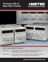
The Fluke 6100AElectrical Power StandardThe most accurate, comprehensive and flexiblesource of electrical power signals
Measurement validation and calibrationfor electrical power applicationsThe importance of accurate measurement ofpower and energy has increased dramaticallyover a relatively short period of time. Deregulation,competition and the increasinglydistributed nature of the power supply networkmean that measurements are made morefrequently, and a higher degree of accuracy isrequired as previously acceptable levels of errorbegin to compound.At the same time, the environment in whichthese measurements are being made is becomingincreasingly hostile to good measurementpractice. Harmonic distortion, voltagefluctuations, phase imbalances and otherextraneous, re-injected signal componentsprovide an alien environment for measurementdevices designed to operate primarily onsinusoidal signals.Additionally, many new measurement andinstrument types have arisen in an attempt to fullycharacterize network performance, and the natureof the product delivered – electricity, flicker andharmonic measurements are becoming ascommonplace as power factor measurements werea few years ago, and even more complexmeasurements such as inter-harmonics are nowbecoming relatively routine. This has resulted inmany more instruments, and many moreinstrument types being used. All of these, ofcourse, require measurement verification andcalibration throughout their life, from initialprototype through to mass deployment in the field.Many national and international standards arein place or are still in development to supportand to bring order to this situation. These set outto ensure measurements have traceability andare comprehensive and consistent. Many alsoaddress the issue of ensuring that measurementsare still valid under real world conditions, andrequire the simulation of such conditions for fullinstrument verification.Against this turbulent change, little progress hasbeen made in the verification of thesemeasurements or the support of these standards.Instruments used to measure and report preciseparameters on power lines carrying significantlydistorted, noisy and fluctuating voltages are stillverified and calibrated under laboratoryconditions. Pure, noise free, levelled sinusoidalvoltages and currents are still routinely applied asreference signals. Custom built systems are stillused to ensure and demonstrate compliance tostandards and to verify some of the newermeasurements.Against this background, Fluke has developedthe 6100A Electrical Power Standard.2
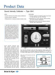
Accuracy and functionalityWho needs a 6100A?Validation of electrical power measurements and the equipment that make them is required in manydisciplines:• In design engineering to guarantee that measurements are being made correctly and accurately• In manufacturing test to make certain that measurements are correct and repeatable on every unitmanufactured• In service and calibration to ensure that instruments continue to perform to specificationthroughout their lifetime• In standards laboratories to ensure measurement techniques and equipment meet appropriatestandards.The Fluke 6100A provides the tools, the functions and the performance to fulfill these requirementscomprehensively, accurately and reliably.Phantom powerThe 6100A will supply pure sinusoidal voltage to 1000 V andcurrent to 21 Amps (optionally to 80 A). Up to 50 VA’s of power isavailable from the voltage terminals to support instruments whichdraw power from the line on which they are measuring.Up to 14 V of compliance is available from the current output toensure current is delivered in setups involving long cable runs,connectors and switches, or where multiple instruments areconnected in series. The current output can also produce anauxiliary voltage of up to 10 V in order to simulate signals that maybe produced by transducers or current probes. Phase anglebetween voltage and current, and between multiple phases, is fullyadjustable by the user from -180 degrees to +180 degrees.In addition to the values of V, I and phase angle set by the user,the on screen display shows calculated values of real power (W),apparent power (VA), various representations of reactive power andpower factor (PF).Outstanding resolution and accuracyThe Fluke 6100A sets a new benchmark for accuracy in powerstandards.Voltage and current are generated with up to 6 digitsresolution and accuracys approaching 100 ppm (0.01 %). Phaseadjustment provides for 1 milli-degree or 10 micro-Radianresolution. Phase performance is exceptional, with accuracy to3 milli-degrees and short term stability to 200 micro-degrees. Inmulti-phase systems phase accuracy between phases is 5 millidegrees,again with short term stability to 200 micro-degrees. Thisoutstanding level of phase performance equals or exceeds anumber of commercially available phase standards.Phase accuracy is imperative in achieving power accuracy. The3 milli-degrees phase accuracy of the Fluke 6100A ensures poweraccuracy approaching 200 ppm (0.02 %) can be achieved. Simpletrigonometry applied to the equation Power = VIcosødemonstrates that compromising phase performance can onlyseverely degrade power uncertainty.3
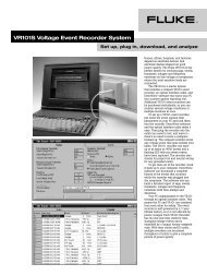
Accuracy and functionalityMulti-phase operationThe 6100A Master unit offers self-containedsingle phase operation, with one voltage and onecurrent output. For multi-phase applications, theaddition of one or more 6101A Auxiliary unitsprovides additional phases, with identicalperformance but without the overhead andadditional complexity of an additional set ofcontrols and display. Additional phases can beadded individually until a maximum of fourphases is reached. In multiphase systems, eachphase remains totally independent andcompletely electrically isolated, yet synchronizedwith, and under the control of the master unit.In multi-phase work, current and voltage on each phase is independently programmable, allowing theuser to simulate unbalance conditions.Energy calibration and verificationThe Fluke 6100A’s energy option provides fullfunctionality for work with energy (watthour)meters, and supports a number of methods ofworking, depending on the users preferenceand the availability of external references andother equipment.For full functionality, the 6100A is equippedwith inputs to receive calibration pulses from themeter or meters under test (single or multiphase).The 6100A is then able to calculateenergy recorded by the meter (according to themeter constant entered by the user), comparethis against energy it has delivered, thencalculate and display errors.If the user prefers to use an externalcomparator, the 6100A is equipped with pulseoutputs. These provide pulses proportional toenergy delivered, again according to the meter constant entered by the user. These pulse streams canthen be compared against equivalent pulses from the meter under test by the external comparator.Complex signalsIn addition to sinusoidal voltages and currents,the 6100A can supply accurate amounts ofharmonic distortion independently on the voltageand current outputs. All of the first 100 harmonicscan be set individually by the user, with levels ofup to 30 % of the fundamental value, theamplitude and phase of each harmonic areindependently controllable by the user. A dclevel is also programmable. Addition ofharmonics does not significantly impair accuracyor compromise traceability of the measurement.This unique capability means that test protocolsusing specific waveshapes such as those definedby IEC 61036 for energy meters can now beimplemented with ease, and with high levels ofconfidence and accuracy.4
Accuracy and functionalityFor more complex work, the 6100A will alsogenerate flicker (compliant to IEC 61000-4-15),interharmonics (compliant to IEC 61000-4-7),and fluctuating harmonics. Dips and swells from 0% to 140 % can be individually programmed onvoltage or current, or both. Dips and swells canbe sub-cycle (from around 1 millisecond) out to 1minute in length. Most of these signal types areavailable simultaneously, so that very complexscenarios are possible. This not only simulates“real world” conditions, but is also a requirementof new standards defining power qualitymeasurement methods such as IEC61000-4-30.The Fluke 6100A enables full compliance to thisinternational standard.User interfaceThe user interface of the 6100A is critical to allow users to exploit its extensive capabilities. To ensuresimplicity of operation, a Microsoft Windows ® user interface has been adopted. The interface can beaccessed through a combination of front panel knobs and buttons, an optional mouse and keyboardand a high resolution, 9-inch TFT display. Status information of all four phases is displayed, alongsidemore detailed information on current parameters being set or adjusted. Frequency domain and timedomain representation of current signal types can be displayed on the screen so that the user is ableevaluate the effect of control settings before applying the signal to the output terminals of the 6100A.At the bottom of the screen a context sensitive help window further guides the operator throughinstrument setup by providing additional control information and error messages.AutomationInstrument setups can be saved and recalled within the instrument or on floppy disk. This provides oneroute for automating complex tasks. A series of complete instrument setups can be stored, and recalledunder user or computer control, thus producing a sequence of steps, or test program. Additionally, the6100A is compatible with Fluke’s MET/CAL ® metrology software package, allowing full automation inaddition to a wide range of other functions such as inventory control.5
6100A and 6101A specificationsPrimary specificationsVoltage/Current amplitude setting resolution6 digitsRange of fundamental frequency16 Hz to 850 HzFrequency accuracy50 ppmFrequency setting resolution0.1 HzWarm up time to full accuracy1 hour or twice the time since last warm upSettling time< 1.4 secondNominal angle between Voltage phases 120 ºNominal angle between Voltage and Current of a phase 0 ºPhase angle setting± 180 º, ± π radiansPhase angle setting resolution0.001 º, 0.00001 radiansSinusoidal Voltage outputRange Frequency Voltage 1 year accuracy, ‘Closed loop’ Stability ‘Open loop’ StabilityTCal ± 5 ºC ± ± (ppm of output ± (ppm of output(ppm of output + mV) + mV) per hour + mV) per hour1.0 V to 16 V 16 Hz – 450 Hz 1.0 V – 6.4 V 122 1.0 40 0.8 200 0.86.4 V – 16 V 112 1.0 40 0.4 200 0.8450 Hz – 850 Hz 1.0 V – 6.4 V 164 1.0 40 0.8 200 0.86.4 V – 16 V 150 1.0 40 0.4 200 0.82.3 V to 33 V 16 Hz – 450 Hz 2.3 V – 13.2 V 122 2.0 40 0.8 200 0.813.2 V – 33 V 112 1.5 40 0.6 200 0.8450 Hz – 850 Hz 2.3 V – 13.2 V 164 2.0 40 0.8 200 0.813.2 V – 33 V 150 1.5 40 0.6 200 0.85.6 V to 78 V 16 Hz – 450 Hz 5.6 V – 31 V 122 2.0 40 0.8 200 0.831 V – 78 V 112 2.0 40 0.6 200 0.8450 Hz – 850 Hz 5.6 V – 31 V 164 2.0 40 0.8 200 0.831 V – 78 V 150 2.0 40 0.6 200 0.811 V to 168 V 16 Hz – 450 Hz 11 V – 67 V 122 4.4 40 1.5 200 1.567 V – 168 V 112 4.4 40 1.5 200 1.5450 Hz – 850 Hz 11 V – 67 V 164 4.4 40 1.5 200 0.867 V – 168 V 150 4.4 40 1.5 200 0.823 V to 336 V 16 Hz – 450 Hz 23 V – 134 V 122 8.8 40 3.0 200 3.0134 V – 336 V 112 8.8 40 3.0 200 3.0450 Hz – 850 Hz 23 V – 134 V 164 8.8 40 3.0 200 0.8134 V – 336 V 150 8.8 40 3.0 200 0.870 V to 1008 V 16 Hz – 450 Hz 70 V – 330 V 166 26 100 10 200 10330 V – 1008 V 158 26 100 10 200 10450 Hz – 850 Hz 70 V – 330 V 190 26 100 10 200 10330 V – 1008 V 175 26 100 10 200 106
6100A and 6101A specificationsVoltage dc and harmonic amplitude specificationsRange Frequency Voltage 1 year accuracy, ‘Closed loop’ Stability ‘Open loop’ StabilityTCal ± 5 ºC ± ± (ppm of output ± (ppm of output(ppm of output + mV) + mV) per hour + mV) per hour1.0 V to 16 V 0 V – 8 V dc 122 5.0 40 1.8 200 1.80 V – 4.8 V 16 Hz – 450 Hz 122 1.0 40 0.8 200 0.8450 Hz – 850 Hz 164 1.0 40 0.8 200 0.8850 Hz – 6 kHz 512 1.0 60 0.8 400 0.82.3 V to 33 V 0 V – 16.5 V dc 122 10 40 3.3 200 3.30 V - 9.9 V 16 Hz – 450 Hz 122 2.0 40 0.8 200 0.8450 Hz – 850 Hz 164 2.0 40 0.8 200 0.8850 Hz – 6 kHz 512 2.0 60 0.8 400 0.85.6 V to 78 V 0 V – 39 V dc 122 24 40 8.0 200 8.00 V - 23 V 16 Hz – 450 Hz 122 2.0 40 0.8 200 0.8450 Hz – 850 Hz 164 2.0 40 0.8 200 0.8850 Hz – 6 kHz 512 2.0 60 0.8 400 0.811 V to 168 V 0 V – 84 V dc 122 50 40 15 200 150 V - 50 V 16 Hz – 450 Hz 122 4.4 40 1.5 200 1.5450 Hz – 850 Hz 164 4.4 40 1.5 200 1.5850 Hz – 6 kHz 512 4.4 60 1.5 400 1.523 V to 336 V 0 V – 168 V dc 122 100 40 30 200 300 V - 100 V 16 Hz – 450 Hz 122 12.0 40 3.0 200 3.0450 Hz – 850 Hz 164 12.0 40 3.0 200 3.0850 Hz – 6 kHz 512 12.0 60 3.0 400 3.070 V to 1008 V 0 V – 504 V dc 166 300 100 100 200 1000 V - 302 V 16 Hz – 450 Hz 166 33 100 10 200 10450 Hz – 850 Hz 190 33 100 10 200 10850 Hz – 6 kHz 524 33 150 10 450 10Voltage from current terminals (Range limits and impedances)Full Range (FR) 0.25 V 1.5 V 10 VMax peak 0.353 V 2.121 V 14.14 VMinimum amplitude 0.05 V 0.15 V 1 VSource impedance 1 Ω 6.67 Ω 40.02 ΩMinimum load impedance to maintain specification 25 kΩ 170 kΩ 1 MΩVoltage from current terminals (Sine specifications)Range Frequency Output 1 year accuracy, ‘Closed loop’ Stability ‘Open loop’ Stabilitycomponent TCal ± 5 ºC ± ± (ppm of output ± (ppm of output(ppm of output + µV) + µV) per hour + µV) per hour0.05 V - 0.25 V 16 Hz – 450 Hz 0.05 V – 0.1 V 200 30 50 15 240 150.1 V – 0.25 V 200 30 50 15 240 15450 Hz – 850 Hz 0.05 V – 0.25 V 231 30 50 15 240 150.15 V - 1.5 V 16 Hz – 450 Hz 0.15 V – 0.6 V 200 50 50 25 240 250.6 V – 1.5 V 200 40 50 20 240 25450 Hz – 850 Hz 0.15 V – 1.5 V 231 50 50 25 240 251 V – 10 V 16 Hz – 450 Hz 1 V – 4 V 200 300 50 150 240 1504 V – 10 V 200 240 50 120 240 150450 Hz – 850 Hz 1 V – 10 V 231 300 50 150 240 1507
6100A and 6101A specificationsCurrent range limitsFull Range (FR) 0.25 A 0.5 A 1 A 2 A 5 A 10 A 21 A 80 AMax peak 0.353 A 0.707 A 1.414 A 2.828 A 7.07 A 14.14 A 28.28 A 113 AMaximum compliance 14 V 14 V 14 V 14 V 14 V 14 V 13 V 2 Vvoltage at FR (Vpk)Sinusoidal Current outputRange Frequency Current 1 year accuracy, ‘Closed loop’ Stability ‘Open loop’ StabilityTCal ± 5 ºC ± ± (ppm of output ± (ppm of output(ppm of output + µA) + µA) per hour + µA) per hour0.01 A - 0.25 A 16 Hz – 450 Hz 0.01 A – 0.1 A 139 6 50 3 240 30.1 A – 0.25 A 130 6 50 3 240 3450 Hz – 850 Hz 0.01 A – 0.1 A 182 6 50 3 360 30.1 A – 0.25 A 170 6 50 3 360 30.05 A - 0.5 A 16 Hz – 450 Hz 0.05 A – 0.2 A 139 12 50 5 240 50.2 A – 0.5 A 130 12 50 5 240 5450 Hz – 850 Hz 0.05 A – 0.2 A 182 12 50 5 360 50.2 A – 0.5 A 170 12 50 5 360 50.1 A -1 A 16 Hz – 450 Hz 0.1 A – 0.4 A 139 24 50 10 240 100.4 A – 1 A 130 24 50 10 240 10450 Hz – 850 Hz 0.1 A – 0.4 A 182 24 50 10 360 100.4 A – 1 A 170 24 50 10 360 100.2 A - 2 A 16 Hz – 450 Hz 0.2 A – 0.8 A 139 48 50 20 240 200.8 A – 2 A 130 48 50 20 240 20450 Hz – 850 Hz 0.2 A – 0.8 A 182 48 50 20 360 200.8 A – 2 A 170 48 50 20 360 200.5 A - 5 A 16 Hz – 450 Hz 0.5 A – 2 A 139 120 50 50 240 502 A – 5 A 130 120 50 50 240 50450 Hz – 850 Hz 0.5 A – 2 A 182 120 50 50 360 502 A – 5 A 170 120 50 50 360 501 A - 10 A 16 Hz – 450 Hz 1 A – 4 A 191 240 70 100 280 1004 A – 10 A 164 240 70 100 280 100450 Hz – 850 Hz 1 A – 4 A 267 240 70 100 420 1004 A – 10 A 250 240 70 100 420 1002 A - 21 A 16 Hz – 450 Hz 2 A – 8 A 213 720 90 300 320 3008 A – 21 A 189 720 90 300 320 300450 Hz – 850 Hz 2 A – 8 A 267 720 90 300 480 3008 A – 21 A 250 720 90 300 480 3008 A – 80 A 40 Hz – 450 Hz 8A – 32 A 265 2800 120 1200 1000 120032 A – 80 A 250 2800 120 1200 1000 1200450 Hz – 850 Hz 8 A – 32 A 300 2800 120 1200 1000 120032 A – 80 A 280 2800 120 1200 1000 1200Applicable only to the 6100A/80A and 6100A/E/80A8
6100A and 6101A specificationsCurrent dc and Harmonic amplitude specificationsRange Output Frequency 1 year accuracy, ‘Closed loop’ Stability ‘Open loop’ StabilityTCal ± 5 ºC ± ± (ppm of output ± (ppm of output(ppm of output + µA) + µA) per hour + µA) per hour0.01 A - 0.25 A 0 A – 0.125 A dc 139 75 50 11 240 110 A – 0. 75 A 16 Hz – 450 Hz 139 6 50 3 240 3450 Hz – 850 Hz 182 6 50 3 360 3850 Hz – 6 kHz 505 6 100 3 1000 30.05 A - 0.5 A 0 A – 0.25 A dc 139 150 50 22 240 220 A – 0.15 A 16 Hz – 450 Hz 139 12 50 5 240 5450 Hz – 850 Hz 182 12 50 5 360 5850 Hz – 6 kHz 505 12 100 5 1000 50.1 A -1 A 0 A – 0.5 A dc 139 300 50 45 240 450 A – 0.3 A 16 Hz – 450 Hz 139 24 50 10 240 10450 Hz – 850 Hz 182 24 50 10 360 10850 Hz – 6 kHz 505 24 100 10 1000 100.2 A - 2 A 0 A – 1 A dc 139 600 50 90 240 900 A – 0.6 A 16 Hz – 450 Hz 139 48 50 20 240 20450 Hz – 850 Hz 182 48 50 20 360 20850 Hz – 6 kHz 505 48 100 20 1000 200.5 A - 5 A 0 A – 2.5 A dc 139 1500 50 225 240 2250 A – 1.5 A 16 Hz – 450 Hz 139 120 50 50 240 50450 Hz – 850 Hz 182 120 50 50 360 50850 Hz – 6 kHz 505 120 100 50 1000 501 A - 10 A 0 A – 5 A dc 191 3000 70 450 280 4500 A – 3 A 16 Hz – 450 Hz 191 240 70 100 280 100450 Hz – 850 Hz 267 240 70 100 420 100850 Hz – 6 kHz 519 240 110 100 1100 1002 A - 21 A 0 A – 10 A dc 213 6000 90 900 320 9000 A - 6 A 16 Hz – 450 Hz 213 720 90 300 320 300450 Hz – 850 Hz 267 720 90 300 480 300850 Hz – 6 kHz 665 720 120 300 1300 3008 A – 80 A 0 A – 24 A 40 Hz – 450 Hz 265 2800 120 1200 1000 1200450 Hz – 850 Hz 300 2800 120 1200 1000 1200850 Hz – 3 kHz 690 2800 150 1200 2000 1200Maximum inductive loading for output stabilityFull range (FR) 0.25 A 0.5 A 1 A 2 A 5 A 10 A 21 A 80 AMaximum inductive 300 µH 300 µH 300 µH 300 µH 300 µH 45 µH 100 µH 30 µHload, hi bandwidthMaximum inductive load, 2 mH 2 mH 1 mH 1 mH 500 µH 360 µH 500 µH 250 µHlo bandwidthApplicable only to the 6100A/80A and 6100A/E/80A9
6100A and 6101A specificationsPhase angle – Current to VoltageFor all voltage ranges Voltage and current components Voltage and current components(16 V to 1008 V) >40 % of range 0.5 % to 40 % of rangeCurrent Range Frequency 1 year accuracy Stability 1 year accuracy StabilityTCal ± 5 ºC per hour TCal ± 5 ºC per hour0.25 A to 5 A 16 Hz – 69 Hz 0.003 ° 0.0002 ° 0.010 ° 0.001 °69 Hz – 180 Hz 0.005 ° 0.0002 ° 0.017 ° 0.002 °180 Hz – 450 Hz 0.015 ° 0.0005 ° 0.050 ° 0.005 °450Hz – 850 Hz 0.030 ° 0.0008 ° 0.070 ° 0.018 °850 Hz – 3 kHz 0.150 ° 0.0010 ° 0.200 ° 0.100 °3 kHz – 6 kHz 0.300 ° 0.0010 ° 0.450 ° 0.100 °5 A to 21 A 16 Hz – 69 Hz 0.004 ° 0.0003 ° 0.013 ° 0.002 °69 Hz – 180 Hz 0.007 ° 0.0003 ° 0.023 ° 0.004 °180 Hz – 450 Hz 0.020 ° 0.0005 ° 0.065 ° 0.010 °450Hz – 850 Hz 0.040 ° 0.0008 ° 0.080 ° 0.020 °850 Hz – 3 kHz 0.200 ° 0.0015 ° 0.250 ° 0.100 °3 kHz – 6 kHz 0.400 ° 0.0020 ° 0.600 ° 0.150 °21 A to 80 A 16 Hz – 69 Hz 0.004 ° 0.0005 ° 0.016 ° 0.003 °69 Hz – 180 Hz 0.008 ° 0.0005 ° 0.028 ° 0.005 °180 Hz – 450 Hz 0.025 ° 0.0010 ° 0.080 ° 0.015 °450Hz – 850 Hz 0.050 ° 0.0015 ° 0.100 ° 0.030 °850 Hz – 3 kHz 0.250 ° 0.0020 ° 0.300 ° 0.150 °Phase Angle – Voltage to Voltage (Multiphase systems)For all voltage ranges Voltage and current components Voltage and current components(16 V to 1008 V) >40 % of range 0.5 % to 40 % of rangeFrequency 1 year accuracy Stability 1 year accuracy StabilityTCal ± 5 ºC per hour TCal ± 5 ºC per hour16 Hz – 69 Hz 0.005 ° 0.0002 ° 0.010 ° 0.001 °69 Hz – 180 Hz 0.007 ° 0.0002 ° 0.018 ° 0.002 °180 Hz – 450 Hz 0.025 ° 0.0005 ° 0.052 ° 0.005 °450 Hz to 850 Hz 0.050 º 0.0008 ° 0.075 ° 0.018 °850 Hz to 3 kHz 0.170 ° 0.0010 ° 0.220 ° 0.100 °3 kHz to 6 kHz 0.350 ° 0.0015 ° 0.400 ° 0.150 °Applicable only to the 6100A/80A and 6100A/E/80A10
6100A and 6101A specificationsPowerThe following tables show in parts per million the minimum to maximum power accuracy for specificvoltage and current bands under sinusoidal conditions.Sinusoidal VACurrentV Rangerange 16 V 33 V 78 V 168 V 336 V 1008 V(6.4 V to 16 V) (13.2 V to 33 V) (31 V to 78 V) (67 V to 168 V) (134 V to 336 V) (330 V to 1008 V)0.1 A to 5 A 233 to 329 220 to 295 206 to 259 207 to 260 207 to 260 240 to 3045.1 A to 10 A 256 to 341 245 to 309 233 to 275 233 to 276 233 to 276 263 to 31710.1 A to 21 A 284 to 373 274 to 344 263 to 314 264 to 315 264 to 315 290 to 35221.1 A to 80 A 347 to 485 339 to 463 330 to 441 330 to 442 330 to 442 352 to 469Sinusoidal Power 16 Hz to 69 Hz, 1.0 > Power Factor > 0.75CurrentV Rangerange 16 V 33 V 78 V 168 V 336 V 1008 V(6.4 V to 16 V) (13.2 V to 33 V) (31 V to 78 V) (67 V to 168 V) (134 V to 336 V) (330 V to 1008 V)0.1 A to 2 A 237 to 323 225 to 288 212 to 252 212 to 253 212 to 253 244 to 2972.1 A to 5 A 241 to 333 229 to 299 215 to 264 216 to 265 216 to 265 248 to 3085.1 A to 10 A 264 to 347 253 to 315 241 to 282 241 to 283 241 to 283 270 to 32310.1 A to 21 A 291 to 378 281 to 350 270 to 320 271 to 321 271 to 321 297 to 35721.1 A to 80 A 398 to 489 391 to 467 383 to 445 384 to 446 384 to 446 402 to 473(Valid for RMS values > 40 % of range for Voltage and Current, not valid when Flicker, Fluctuating Harmonics, Dips/Swells orInterharmonics are applied)Sinusoidal Power 16 Hz to 69 Hz, 0.75 > Power Factor > 0.5CurrentV Rangerange 16 V 33 V 78 V 168 V 336 V 1008 V(6.4 V to 16 V) (13.2 V to 33 V) (31 V to 78 V) (67 V to 168 V) (134 V to 336 V) (330 V to 1008 V)0.1 A to 2 A 250 to 332 238 to 299 225 to 264 226 to 264 226 to 264 257 to 3072.1 A to 5 A 262 to 349 251 to 317 239 to 284 240 to 285 240 to 285 269 to 3255.1 A to 10 A 283 to 362 273 to 332 262 to 300 263 to 301 263 to 301 290 to 34010.1 A to 21 A 309 to 393 300 to 365 290 to 337 290 to 337 290 to 337 315 to 37221.1 A to 80 A 411 to 500 404 to 478 397 to 457 397 to 458 397 to 458 416 to 484(Valid for RMS values > 40 % of range for Voltage and Current, not valid when Flicker, Fluctuating Harmonics, Dips/Swells orInterharmonics are applied)Sinusoidal Power 16 Hz to 69 Hz, 0.5 > Power Factor > 0.25CurrentV Rangerange 16 V 33 V 78 V 168 V 336 V 1008 V(6.4 V to 16 V) (13.2 V to 33 V) (31 V to 78 V) (67 V to 168 V) (134 V to 336 V) (330 V to 1008 V)0.1 A to 2.1 A 309 to 378 299 to 349 289 to 320 290 to 321 290 to 321 314 to 3572.1 A to 5 A 357 to 424 349 to 399 340 to 373 340 to 374 340 to 374 362 to 4055.1 A to 10 A 373 to 435 365 to 410 357 to 386 357 to 386 357 to 386 377 to 41710.1 A to 21 A 392 to 461 385 to 438 377 to 414 378 to 415 378 to 415 397 to 44421.1 A to 80 A 477 to 555 471 to 536 465 to 517 465 to 518 465 to 518 481 to 541(Valid for RMS values > 40 % of range for Voltage and Current, not valid when Flicker, Fluctuating Harmonics, Dips/Swells orInterharmonics are applied)Applicable only to the 6100A/80A and 6100A/E/80A11
6100A and 6101A specificationsHarmonicsNumber of Harmonics availableMaximum Harmonic frequency availableMaximum level of individual HarmonicSetting method (user selectable)100 (simultaneously if required)6 kHz (100th Harmonic of 60 Hz)30 % of full range% RMS, % fundamental, dB down from fundamental, absolute valueFlickerSetting rangeFlicker modulation depth accuracy 0.025 %Modulation depth setting resolution 0.001 %ShapeFluctuating HarmonicsNumber of Harmonics to fluctuateModulation depth setting rangeFluctuation accuracy (0 % to ± 30 % modulation) 0.025 %Modulation depth setting resolution 0.001 %ShapeAny number from 0 to all set Harmonics can fluctuate0 % to 100 % of nominal Harmonic voltageRectangular or sinusoidalDuty cycle (shape = rectangular) 0.1 % to 99.99 %Modulating frequency range0.008 Hz to 30 HzNot available on Voltage or Current channels if Flicker is already enabled on that channelInterharmonicsFrequency accuracy500 ppmAmplitude accuracy 16 Hz to < 6 kHz 1 %Amplitude accuracy > 6 kHz 4 %Maximum value of a single InterharmonicThe maximum value for an Interharmonic < 2850 Hz is 30 % of range.Frequency range of Interharmonic16 Hz to 9 kHzDips and Swells±30 % of set voltage or current within range values (60% ∆V/V)Rectangular or sinusoidalDuty cycle (shape = rectangular) 0.01 % to 99.99 %Modulating frequency range0.0008 Hz to 40 HzPst indication accuracy0.25 % Valid for voltage only between 220 V and 240 VAlthough Flicker is Voltage phenomena the 6100A will provide Flicker on its Current output. Flicker is not available if FluctuatingHarmonics are already enabled on that channel.Dip/Swell Minimum duration 1 µsDip/Swell Maximum duration1 minuteDip Minimum amplitude0 % of the nominal outputSwell Maximum amplitudeThe least of full range value and 140 % of the nominal outputRamp up/down periodSettable 100 µs to 30 secondsOptional repeat with delay 0 to 60 seconds ± 31 µsStarting level amplitude accuracy±0.025 % of levelDip/Swell level amplitude accuracy±0.25 % of levelTrigger outTTL falling edge co-incident with end of trigger out delay, remaining lowfor 10 µs to 31 µs12
6100A/E specificationsPulse InputsMaximum frequency5 MHzMinimum pulse width60 nsMaximum counts per channel 2 32 -1 (4,294,967,295)Pulse and Gate InputsInput Low level maximumInput High level minimumInternal pull-up valuesMaximum input voltageMinimum input voltage1 V3 V135 Ω and 940 Ω to 4.5 V nominal(Approximately equivalent to 150 Ω/1k Ω to 5V nominal)28 V (clamped @ 30 V approximately)0 V (clamped @ -0.5 V approximately)Pulse OutputDriveOpen-collector with optional 470 Ω pull-upFrequency range0.011 Hz - 5 MHzFrequency accuracy ± ( 50 ppm + 107 nHz )External pull-up voltage30 V maximum (clamped)Sink current150 mA maximumGate OutputDriveInternal pull-upExternal pull-up voltageSink currentOpen-drainAs Gate-Input30 V maximum (clamped)1 A maximumAccuracyCounted/Timed timing accuracy ± ( 50 ppm + 60 ns )Packet mode accuracy (ppm) ± ( output power (ppm) + 50 ppm + 101,000/Test Duration (secs) )When very low pulse input rates are used (
General specificationsPowerVoltage100 V to 240 V with up to ± 10 % fluctuationsTransient overvoltages Impulse withstand (overvoltage) category II of IEC 60364-4-443Frequency47 Hz to 63 HzMaximum consumption1000 VA maximum from 100 V to 130 V, 1250 VA maximum from 130 V to 260 VDimensions6100A, 6101A and 6100A/E 6100A/80 A, 6101A/80 A and 6101A/E/80 AHeight 233 mm (9.17 inches) 324 mm (12.8 inches)Height (without feet) 219 mm (8.6 inches) 310 mm (12.2 inches)Width 432 mm (17 inches) 432 mm (17 inches)Depth 630 mm (24.8 inches) 630 mm (24.8 inches)Weight 23 kg (51 lb) 30 kg (66 lb)EnvironmentOperating temperature 5 ºC to 35 ºCCalibration temperature (TCal) range 16 ºC to 30 ºCStorage temperature 0 ºC to 50 ºCTransit temperature-20 ºC to 60 ºC < 100 hoursWarm up time1 hourSafe operating maximum relative humidity < 80 % 5 ºC to 31 ºC ramping linearly down to 50 % at 35 ºC(non-condensing)Storage maximum relative humidity
6100A Electrical Power StandardOrdering informationModel6100A Electrical Power Standard Mastercomprises:• One phase, (one voltage channel to 1000 V, onecurrent channel to 21 A)• User controls and display system• Interfacing via GPIB/RS232• Interfacing to Auxiliary Unit• Line cord• Lead kit• User manual6101A Auxiliary Power Standard comprises:• One phase, (one voltage channel to 1000 V, onecurrent channel to 21 A)• Cable and interfacing to connect to Master• Line cord• Lead kit6100A/80A Electrical Power Standard Mastercomprises:• One phase, (one voltage channel to 1000 V, onecurrent channel to 80 A)• User controls and display system• Interfacing via GPIB/RS232• Interfacing to Auxiliary Unit• Line cord• Lead kit• User manual6101A/80A Auxiliary Power Standard comprises:• One phase, (one voltage channel to 1000 V, onecurrent channel to 80 A)• Cable and interfacing to connect to Master• Line cord• Lead kit6100A/E Electrical Power Standard Mastercomprises:• One phase, (one voltage channel to 1000 V, onecurrent channel to 21 A) with energy counting optionfitted• User controls and display system• Interfacing via GPIB/RS232• Interfacing to Auxiliary Unit• Line cord• Lead kit• User manual6100A/E/80A Electrical Power Standardcomprises:• One phase, (one voltage channel to 1000 V, onecurrent channel to 80 A) with energy counting optionfitted• Cable and interfacing to connect to Master• Line cord• Lead kit• User manualComplete systems6120A complete 2-phase system comprises:• One 6100A• One 6101A6130A complete 3-phase system comprises:• One 6100A• Two 6101As6140A complete 4-phase system comprises:• One 6100A• Three 6101AsComplete 6100A/80A systems6120A/80A complete 2-phase system comprises:• One 6100 A/80A• One 6101 A/80A6130A/80A complete 3-phase system comprises:• One 6100A/80A• Two 6101A/80As6140A/80A complete 4-phase system comprises:• One 6100A/80A• Three 6101A/80AsComplete 6100A/E systems6120A/E complete 2-phase system comprises:• One 6100A/E• One 6101A6130A/E complete 3-phase system comprises:• One 6100A/E• Two 6101As6140A/E complete 4-phase system comprises:• One 6100A/E• Three 6101AsComplete 6100A/E/80A systems6120A/E/80A complete 2-phase systemcomprises:• One 6100A/E/80A• One 6101A/80A6130A/E/80A complete 3-phase systemcomprises:• One 6100A/E/80A• Two 6101A/80As6140A/E/80A complete 4-phase systemcomprises:• One 6100A/E/80A• Three 6101A/80AsAccessories6100-CASE6100A/6101A Transit caseY61006100A/6101A Rack Mount Kit15
6100A Electrical Power Standard6100A Electrical Power Standard6101A Auxiliary Power Standard6100A/E Electrical Power Standard6100A/80A Electrical Power StandardFluke. Keeping your worldup and running.Fluke CorporationPO Box 9090, Everett,WA USA 98206Fluke Europe B.V.PO Box 1186, 5602 BDEindhoven, The NetherlandsFluke Precision Measurement <strong>Ltd</strong> (UK)Hurricane Way, Norwich, NorfolkNR6 6JB, UK6100A/E/80A Electrical Power StandardFor more information call:In the U.S.A. (800) 443-5853 orFax (425) 446-5116In Europe/M-East/Africa (31 40) 2 675 200 orFax (31 40) 2 675 222In Canada (800)-36-FLUKE orFax (905) 890-6866From other countries (425) 446-5500 orFax (425) 446-5116Web access: http://www.fluke.com2003 Fluke Corporation. All rights reserved.©Trademarks are the property of their respective owners.Printed in the U.K. by Graphics Matter <strong>Ltd</strong>. 10/2003 1779013 B-ENG-N B, DS264