T2550 Installation & Wiring Sheet - Eurotherm Ltda
T2550 Installation & Wiring Sheet - Eurotherm Ltda
T2550 Installation & Wiring Sheet - Eurotherm Ltda
- TAGS
- installation
- wiring
- eurotherm
- ltda

Create successful ePaper yourself
Turn your PDF publications into a flip-book with our unique Google optimized e-Paper software.
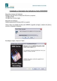
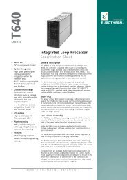
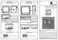
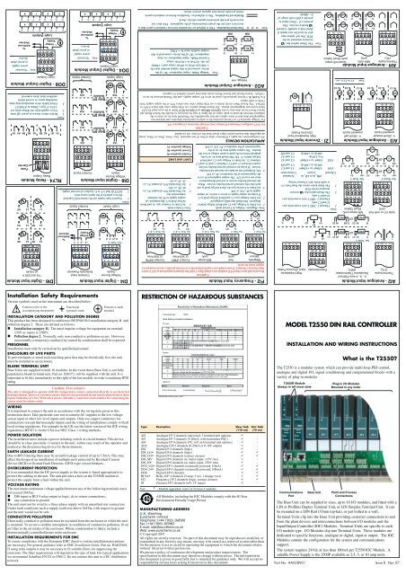
The Base UnitTO MOUNT THE BASEThis unit is intended to be mounted within an enclosure, or in an environmentsuitable for IP20 rated equipment. It can be DIN rail or bulkhead mounted.Illustration Key(1) Retention Screws(2) Base Retention Clip(3) DIN Rail(4) Side Cover(5) Terminal UnitRetention Clip(6) Support for TerminalUnit(7) EMC Earthing(8) Protective EarthTerminal Strip(* - Optional)Note.Always ensure a25mm clearancefor ventilation.(4)CD(6)(1)(2)EDIN RAIL MOUNTING (HORIZONTAL)1. Mount the DIN rail horizontally, using suitable bolts.2. Ensure that the DIN rail makes good electrical contact with the metal base of theenclosure.3. Loosen screws (1) in the base, and allow them, and the associated base retentionclips (2) to drop to the bottom of he screw slot.4. In the back of the base is an extruded slot which locates with the DIN rail(3).5. Fit the top edges of this into the top edge of the DIN rail (3). Slide the screws (1)with the associated clips (2) upwards as far as they will go towards the top of thescrew slots. The angled edge of the base retaining clip (2) must locate behind thebottom edge of the DIN rail.6. Tighen the screws (1).DIN RAIL MOUNTING (VERTICAL)CautionIt is acceptable to mount the base vertically. If it is mounted vertically, however, it isadvisable to fit a fan in the cubicle to ensure a free flow of air around the modules.1. Mount the DIN rail vertically, using suitable bolts.2. Ensure that the DIN rail makes good electrical contact with the metal base of theenclosure.3. Loosen screws (1) in the base, and move them and the associated base retentionclips (2) to the bottom of the screw slot.4. In the back of the base is an extruded slot which locates with the DIN rail (3)5. Fit the top edge of this into the top edge of the DIN rail (3)6. Slide the screws (1) with the associated clips (2) upwards as far as they will gotowards the top of the screw slots. The angled edge of the base retaining clip (2)must locate behind the bottom edge of the DIN rail.7. Tighten the screws.DIRECT PANEL MOUNTING1. Remove the screws (1) and base retention clips (2).2. Hold the base horizontally or vertically on the panel and mark the position of thetwo holes on the panel.3. Drill two 5.2mm holes in the panel.4. Using M5 bolts supplied, secure the base to the metal panel.A(8) (*8)(7)(8)(4)(3)(1)(2)Module Dimensions Weight (kg)Base Unit A B C D E No Modules All Modules<strong>T2550</strong>B - 00S 36 180 68 15 5 0.6 1.0<strong>T2550</strong>B - 04R 164 180 68 15 5 0.7 1.1<strong>T2550</strong>B - 06R 214 180 68 15 5 0.9 1.3<strong>T2550</strong>B - 08R 264 180 68 15 5 1.2 1.8<strong>T2550</strong>B - 16R 467 180 68 15 5 2.5 3.0(5)(1)(2)B! CautionDo not operate the equipment without a protective earth conductor connected to one ofthe earth terminals on the base unit. The earth cable should have at least the currentrating of the largest power cable used to connect to the unit.Connect the protective earth with a suitable tinned copper eyelet, and use the screwand washer supplied with the base unit, tightened to a torque of 1.2Nm (910.5lbin).This connection also provides a ground for EMC purposes.For DIN rail mounting, use symmetrical DIN rail to EN50022-35 X 7.5 or 35 X 15mounted horizontally or vertically.Connecting the 24Vdc Power SupplyCautionBefore proceeding with any wiring on this unit, please read section on <strong>Wiring</strong>, and Safetyand EMC information. It is the responsibility of the installer to ensure the safety andEMC compliance of any particular installation.The power supply is the 2500P. This is a DIN rail mounted unit, which may be mountedadjacent to the base or remotely. Alternatively, an existing power supply may be usedprovided it meets the specification below.The IOC terminal unit is not fused, but is diode protected against connection of a reversedpolarity supply. Connection of a reversed polarity supply will not damage the unit. Allmodules are individually fused. The fuse is not user replaceable, therefore the unit mustbe returned to the factory for replacement.POWER SUPPLY SPECIFICATIONPower supply voltage:Supply ripple:Power comsumption:Note.18.0Vdc min to 28Vdc max2Vp-p max90W max per baseThe current taken by each module is 100mA on average. 18V is the absolutelower limit. The use of an 18V Power Supply with any appreciable voltage dropmay cause unpredictable or out of specification operation. Damage may occurwhen a supply voltage >30Vdc is used.Assembling I/O Modules & Terminal UnitsTO FIT TERMINAL UNITTerminal UnitRetention clip2 1TO FIT A MODULEBase UnitTerminalUnitDIN RailBackplaneConnectorEMCEarthing StrapPlant and ProcessConnections1. Locate tag on the Terminal Unit PCBwith the slot in the Base.2. Press the lower end of the TerminalUnit until secured in place by theRetention clip. This is indicated by a‘click’ as the clip locks into place.To remove simply press the Retentionclip to release the Terminal Unit andwithdraw it from the slot in the BaseUnit.Modules are locked into positionusing the Retaining lever on the faceof the module.The module must be fitted andremoved with the Retaining lever inthe open ( ) position, as shown inthis side view.Once fitted the lever is closed tosecurely lock the module in place.Setting the IP AddressEach instrument uses a one-to-one mapping of LIN Node Number to an IP Addressdefined by the ‘network.unh‘ file.Note.The Compact Flash card is accessed using a standard Compact Flash cardreader. The ‘network.unh‘ file MUST be edited using the InstrumentPorperties dialog. It can be edited using a text editor program,e.g. ‘notepad.exe’, but this is not recommmended.ALLOCATION OF IP ADDRESSDHCP is where the instrument (IP host) will ask a DHCP server to provide it with anIP Address. Typically this happens at start-up, but can be repeated during operation.DHCP includes the concept of assigned values that will ‘expire’.A DHCP server is required that can respond to the request. The DHCP server willneed to be configured to correctly respond to the request. This configuration dependson the local company network policy.BootP or Bootstrap Protocol (Internet (TCP/IP protocol)) is used by a networkcomputer to obtain an IP Address and other network information such as serveraddress and Default Gateway. Upon startup, the client station sends out a BOOTPrequest to the BOOTP server, which returns the required information. A BootPtimeoutperiod can be configured. If this period elapses before the IP Address, Subnet mask,and Default Gateway address are obtained, the values will display 0.0.0.0.Link-Local is used as a fallback to either DHCP or BootP, or can be used on its ownas the only IP Address configuration method. Link-Local will always assign an IPAddress in the range 169.254.X.Y. This IP Address range is reserved for use byLink-Local and is explicitly defined as private and non-routable.The Link-Local algorithm ensures that an instrument (IP host) on a network will chosea unique IP Address from the Link-Local range.This is supported by Windows 98 and onwards, and was originally specified as afallback from DHCP.Manual requires the IP Address to be explicitly defined in the ‘network.unh‘ file.EDITING THE NETWORK SETTINGSEach instrument uses a one-to-one mapping of, LIN Node Number to a single IPAddress, defined in the Instrument Properties dialog.When despatched from the factory, theinstrument is configured using DHCPwith Link-Local Fallback, and adefault LIN Network name, ‘NET’.However, if the instrument is to have afixed IP Address, i.e. 192.168.111.2,and use the LIN Protocol Name,‘PLANT’, the Instrument Propertiesdialog must be used to modify theseparameters.Note.RECOVERY FROM UNKNOWN IP ADDRESS CONFIGURATIONTo reset the IP Address, and Subnet Mask (255.255.255.0) of an Instrument with anunknown IP Address when a Compact Flash card reader is not available, set the LINAddress switches as denoted below.IOC Unit LIN Address Switches In Position For IP AddressSimplex Unit ALL (SW1:S1 to SW1:S8) OFF 192.168.111.222Duplex UnitSimplex Mode ALL (SW1:S1 to SW1:S8) OFF 192.168.111.222Duplex Mode ALL (SW1:S1 to SW1:S8) ON Left - 192.168.111.222Right - 192.168.111.223A Computer with a fixed IP Address on this Subnet can then be connected directly tothe instrument and used to inspect and edit the IP Address of the <strong>T2550</strong> IOC module.Note.The IP Address must correspond tothe local company Network Policy.To display the Instrument Propertiesdialog, select the Properties command afterselecting the Instrument Folder in anappropriate Explorer view.Use the Instrument Properties dialog to edit the IP Address. The TerminalConfigurator may also be used, but this is not recommended.Terminal Unit (Simplex and Duplex Unit)The Terminal Units have links andswitches for configuring theMode, LIN address andinstrument Restart options. TheSimplex Unit uses one set of 10switches to set theseconfigurations. The Duplex Unithas one set of 8 switches, SW1, toconfigure the Duplex operationand instrument LIN address, andone set of 4 switches, SW2, to setthe instrument restartconfiguration.The Ethernet PortThis is a 10/100base T port. It canbe connected to a hub or switchwith Cat5 cable via the RJ45connector to create a network ofTactician instruments, including arange of operator interface units,and to interface with devicessupporting Modbus-TCP as amaster or a slave.The Terminal Unit will autonegotiate if connected directly to a device supporting10/100base T Ethernet, so RJ45 cross-over cables not required.BATTERY SUPPORTThe Simplex Unit supports Battery backup via the Lithium Manganese Dioxidebattery, maintaining the Real-Time Clock for 1.5 years continuous use.WarningIf batteries are abused, a caustic solution may leak that can result in the corrosionof aluminium and copper. The caustic solution must be neutralised using a weakacidic solution, i.e. vinegar, or washed away with copious amounts of water.Batteries must be disposed of according to current local regulations, and notdiscarded with normal refuse.The Duplex Unit supports external Battery backup only.CONNECTIONS TO RJ45 SOCKETRJ45 Pin Colour Signal8 Brown Not Used7 Brown/White Not Used6 Green RX-5 Blue/White Not Used4 Blue Not Used3 Green/White RX+2 Orange TX-1 Orange/White TX+Plug shroud to Cable screenOptionsswitchesAddressswitchesModuleconnectors422/485JumpersBatteryHolderBatteryconnectorP+ P- P+ P-P+ P-Positive Negative Redundant24v24v dc supply dc supplyNote. The power supply connections alsoapply to the Profibus Terminal UnitWarningCABLE COLOURSMAY CHANGE!SW1: LIN ADDRESS CONFIGURATIONSIn Duplex mode, the primary is initially in the left-hand (even address) first slot andthe secondary, the right-hand (odd address) second slot. If the secondary must takeover, and become the primary, it will also take over the even address.In Simplex mode, it always adopts the even address. It is strongly recommended thatthe odd address remains unallocated on this LIN segment to avoid address clashes if asecond module is subsequently added.A Simplex Unit always adopts the even address. It is strongly recommended that theodd address remains unallocated on this LIN segment.Simplex Terminal UnitOn (1)SW1: Function100 0111 110XSimplex Only (See SW2 Note below).908 Addr. Bit 7 (MSB, value 128) MSB 0 Bit77 Addr. Bit 616 Addr. Bit 515 Addr. Bit 414 Addr. Bit 313 Addr. Bit 212 Addr. Bit 1 (LSB, value 2) LSB1 Not Used10 Bit1Duplex Terminal UnitSW1: Function8 Addr. Bit 7 (MSB, value 128)7 Addr. Bit 66 Addr. Bit 55 Addr. Bit 44 Addr. Bit 33 Addr. Bit 22 Addr. Bit 1 (LSB, value 2)1 On = Duplex, Off = SimplexSW2: OPTION CONFIGURATIONSSW2: Function4 Not Used321Duplex Only (See Note below).On = Restart after WatchdogOff = Remain in Reset11Serial Communications (Modbus & Profibus)The Serial network supports Modbusand ProfiBus communicationsprotocols. Modbus communicationsare via the RJ45 connector on theTerminal Unit, but Profibuscommunications are via a standard9-way D-Type connector on adedicated Profibus Terminal Unit.The system power connections(standard screw terminals) are providedby the Terminal Unit.The Serial connection may be used toconnect to an operator interface unit,create a Modbus or Profibus networkor communicate with a variety of thirdpartyserial devices.BAUD RATEIn Modbus networks, each instrumentbaud rate is configured via theInstrument Properties dialog, andMUST be set the same for both theinstrument transmitting and theinstrument receiving data.In Profibus networks, the Baud Rate isis defined by the Profibus Master, bydetecting the fastest Baud Rate that alldevices can operate. The ProfibusTerminal Unit operates at 12M Baud.On (1)0111 110XMSB 0 Bit711111LSB 0 Bit11On (1)00ModbusComms ports(RS422/485)Binary Hex0000 00001 10010 20011 30100 40101 50110 60111 71000 81001 91010 A1011 B1100 C1101 D1110 E1111 FNote. ‘Hot/Cold’ start-up.Bit 2(9) Bit 3(10) FunctionOff Off Automatic database generation.On Off Attempt cold start. Halt if fails.Off On Attempt hot start. Halt if fails.On On Attempt hot start, if failed attempt cold start. Halt if fails.ModuleconnectorAddressswitchesBatteryconnector9-way D-TypeProfibus CommsconnectorP+ P- 24v dc supplyP+ P- Redundant24v dc supplySERIAL NETWORK CONNECTOR (EIA 485)ModbusFit applicable links as shown:Link Pos Terminal Unit Profibus Terminal UnitLK1 and LK2 1-2 2 (3) wire (default) Profibus Network TerminatedLK1 and LK2 2-3 4 (5) wireProfibus Network Unterminated (default)ADDRESS CONFIGURATIONSProfibus Address configurations from 1to 127 must be set in the InstrumentProperties dialog via the InstrumentFolder or Modbus Tools. 0 is aninvalid address, and when configuring aduplex Profibus system the lastpermitted Address configuration is 125,to allow an even address, e.g. 126, forthe second IOC in the redundant pair.Note.81LINK CONFIGURATIONDUPLEX UNITLK1Label1Moulding colour,Black (<strong>T2550</strong>A/Term)LK21MB120AN100120Ω 5%120Ω 5%Explicit Modbus Registers, in Modbus Tools MUST be configured to permitProfibus Slave communications, see Instrument Handbook.81SIMPLEX UNITProfibusPin Colour 3-wire signal 5-wire signal Pin Signal Description- - - - 9 Not Used N/A8 Brown N/A RxA 8 A Receive/Transmit A7 Brown/White N/A RxB 7 Not Used N/A6 Green Cmn Cmn 6 VP 5V5 Blue/White N/A N/A 5 Cmn Signal Common4 Blue N/A N/A 4 Not Used N/A3 Green/White Cmn Cmn 3 B Receive/Transmit B2 Orange A TxA 2 Not Used N/A1 Orange/White B TxB 1 Shield Shield (ground)Plug shroud to Cable screenWarningCABLE COLOURS MAY CHANGE!COMMUNICATIONS LINE TERMINATORThe communications line MUST be terminated ONLY on the last device in the chainusing the appropriate load resistors. To minimise on site wiring and to provide thecorrect resistor values, ‘Terminators’ are available from your distributor.RJ45 LINE TERMINATIONThe Modbus TCP/IP RJ45 line terminator, <strong>T2550</strong>A/Term, is plugged into the last RJ45socket in the chain. If the operating interface is a PC or PLC this should be terminatedin accordance using the appropriate load resistors.120Ω 5%LK2LK111