IGEA BT
IGEA BT
IGEA BT

You also want an ePaper? Increase the reach of your titles
YUMPU automatically turns print PDFs into web optimized ePapers that Google loves.
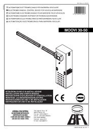
<strong>IGEA</strong> <strong>BT</strong>Thank you for buying this product. Our company is sure that you will bemore than satisfied with the product’s performance.Carefully read the “WARNINGS” pamphlet and the “INSTRUCTIONBOOKLET” which are supplied together with this product, since theyprovide important information regarding the safety, installation, use andmaintenance of the product. This product complies with recognised technicalstandards and safety regulations. We declare that this product is inconformity with the following European Directives: 73/23/ EEC, 89/336/EEC, 98/37/EEC and subsequent amendments.WARNING! The installation, the maintenance and the repair should bedone by responsible and qualified persons with an updated knowledge ofthe current safety standards. It’s strictly forbidden to service the automationwhen the power is on.ATTENTION! The <strong>IGEA</strong>-<strong>BT</strong> model controller is not equipped with mechanicaltorque adjustment. It is compulsory to use a control panel of the samemanufacturer, in compliance with the basic safety requirements of directives73/23/CEE, 89/336/CEE, 89/37/CEE equipped with appropriate electricadjusment of the torque.D811369_011) GENERAL SAFETYWARNING! An incorrect installation or improper use of the productcan cause damage to persons, animals or things.• The “Warnings” leaflet and “Instruction booklet” supplied with thisproduct should be read carefully as they provide important informationabout safety, installation, use and maintenance.• Scrap packing materials (plastic, cardboard, polystyrene etc) accordingto the provisions set out by current standards. Keep nylon or polystyrenebags out of children’s reach.• Keep the instructions together with the technical brochure for futurereference.• This product was exclusively designed and manufactured for the usespecified in the present documentation. Any other use not specified inthis documentation could damage the product and be dangerous.• The Company declines all responsibility for any consequences resultingfrom improper use of the product, or use which is different from thatexpected and specified in the present documentation.• Do not install the product in explosive atmosphere.• The construction components of this product must comply with thefollowing European Directives: 89/336/CEE, 73/23/EEC, 98/37/EEC andsubsequent amendments. As for all non-EEC countries, the abovementionedstandards as well as the current national standards shouldbe respected in order to achieve a good safety level.• The Company declines all responsibility for any consequences resultingfrom failure to observe Good Technical Practice when constructing closingstructures (door, gates etc.), as well as from any deformation which mightoccur during use.• The installation must comply with the provisions set out by the followingEuropean Directives: 89/336/CEE, 73/23/EEC, 98/37/EEC andsubsequent amendments.• Disconnect the electrical power supply before carrying out any work onthe installation. Also disconnect any buffer batteries, if fitted.• Fit an omnipolar or magnetothermal switch on the mains power supply,having a contact opening distance equal to or greater than 3mm.• Check that a differential switch with a 0.03A threshold is fitted just beforethe power supply mains.• Check that earthing is carried out correctly: connect all metal parts forclosure (doors, gates etc.) and all system components provided with anearth terminal.• Fit all the safety devices (photocells, electric edges etc.) which are neededto protect the area from any danger caused by squashing, conveyingand shearing, according to and in compliance with the applicabledirectives and technical standards.• Position at least one luminous signal indication device (blinker) where itcan be easily seen, and fix a Warning sign to the structure.• The Company declines all responsibility with respect to the automationsafety and correct operation when other manufacturers’ components areused.• Only use original parts for any maintenance or repair operation.• Do not modify the automation components, unless explicitly authorisedby the company.• Instruct the product user about the control systems provided and themanual opening operation in case of emergency.• Do not allow persons or children to remain in the automation operationarea.• Keep radio control or other control devices out of children’s reach, inorder to avoid unintentional automation activation.• The user must avoid any attempt to carry out work or repair on theautomation system, and always request the assistance of qualifiedpersonnel.• Anything which is not expressly provided for in the present instructions,is not allowed.2) GENERAL OUTLINEThis Low-voltage controller (24V) is suitable for residential use and hasbeen designed for swing gates with particularly large gate posts. The drivearm, built with a special anti-shearing shape, allows the leaves to be movedwhen the controller is considerably out of place with respect to the fulcrumof the leaves. The non-reversible electro-mechanical gearmotor maintainsthe stop during closing and opening.The release knob with personalised key, fitted outside each operator,makes manual manoeuvre extremely easy.AUTOMATION FOR SWING GATES3) TECHNICAL SPECIFICATIONSMotor: .............................................................................. 24V 1500 min -1Power: ..................................................................................................40WInsulation class: ........................................................................................ FLubrication: ................................................................... Permanent greaseReduction radio: ............................................................................... 1: 812Output shaft revolutions: ...................................................... 1.8 min -1 MAX90° opening time: ................................................................................. 15sTorque supplied: ............................................................................ 300 NmWeight and max leaf length: ........... 2000N (~200kg) for 2.5m leaf length2500N (~250kg) for 2m leaf lengthImpact reaction: ............ Integrated torque limiter on LIBRA control panelMotion drive: ...............................................................................Lever armStop:.................................................... Incorporated electric limit switchesManual manoeuvre: ......................... Release knob with personalised keyNumber of manoeuvres in 24h: .............................................................. 40Environmental conditions: ..................................................... -15 to +60°CDegree of protection: ......................................................................... IP 44Operator weight: ................................................................... 160N (~16kg)Dimensions: ................................................................................ See fig. 14) OPERATOR INSTALLATION4.1) Preliminary checksCheck that:• The gate structure is sufficiently sturdy and rigid.The fixing position must be worked out according to the leaf structure. Inany case, the manoeuvring arm must push against a reinforced leafpoint (fig. 2).• The leaves can be moved manually along their entire stroke.If the gate has not been installed recently, check the wear condition of allits components. Repair or replace defective and worn parts.Operator reliability and safety are directly affected by the condition ofthe gate structure.4.2) Fitting of the manual release knob• With reference to fig. 9, position release knob “A” on flange “B” prefittedon the cover.• Insert adapting ring “C” in the bush with release tooth “D”.WARNING: Depending on the operator installation position (right orleft side), insert ring “C” and position bush “D” as shown in fig. 9.• Insert space washer “E” and then shimming thrust bearing “F” into bush”D” on the release tooth side.• Secure everything, using appropriate self-tapping screw “G” inside theoperator cover, checking the correct positioning of ring “C” and bush “D”.• Close the operator cover, using the appropriate screws supplied.WARNING: The release tooth on bush “D” must be inserted in therelease lever as shown in fig. 9b. Otherwise, the emergencymanoeuvre cannot be carried out.Insertion is made easy by turning knob “A” to the side opposite to that formanual release (clockwise in the case of a left-hand leaf, anticlockwisein the case of a right-hand leaf) and locking it in such position by meansof the appropriate key.Check that bush “D” is placed horizontally (fig. 9b) and close the coverby positioning its front side (the one with the release knob) as indicatedin fig. 9c.• Before connecting the operator to the power supply, manually checkthat the release knob operates correctly.5) FIXING OF SUPPORTING PLATE (Fig.2)The controller is supplied complete with anchoring bracket and lever arm.Once the reinforcement point of the leaf has been identified with the gateclosed, draw an imaginary horizontal line from the centre of the reinforcementpoint to the gate post (fig.2). Position the anchoring bracket according to thevalues given in fig. 2 for openings of up to 90° or in fig.3 for openings greaterthan 90° up to a maximum of 125°.The bracket fixing position must be flat and parallel to the leaf. Use screwsor expansion bolts which are suited to the type of gate post. If the surfaceof the gate post is not regular, use expansion bolts with studs so that theparallel plate of the leaf can be adjusted (fig.4).• Fasten the gearmotor to the gate post using the 4 screws, pointing thegearmotor to the left or the right (fig.5).11141
<strong>IGEA</strong> <strong>BT</strong>142• Assemble the lever arm as shown in fig.6.DX= assembly on the right leafSX= assemby on the left leafChoose the most suitable position of ‘F’ bracket for the fastening to theleaf.• Insert the square of the first lever in the output shaft of the gearmotorand fasten it (fig.7).• Release the operator by turning the release knob to allow easy movementof the arm (see paragraph on “EMERGENCY MANOEUVRE”).• The correct position for the controller arm is shown in fig.8.The leaf fixing point can be identified by positioning the arm so that it isin accordance with the distance shown in fig.8.• Fix the angular towing bar “F” to the leaf by welding or using screws.• With the controller released, check the correct movement of the arm.• Repeat the same operation for the other leaf, if installed.6) ELECTRICAL INSTALLATION SET-UPArrange the electrical installation as shown in fig.10.The power supply connections must be kept separate from the auxiliaryconnections (photocells, sensitive edge, etc.). Fig.10 shows the crosssectionand the number of connections.WARNING! For connection to the mains, use a multipolar cable witha minimum of 3x1.5mm 2 cross section and complying with thepreviously mentioned regulations. For example, if the cable is out side(in the open), it has to be at least equal to H07RN-F, but if it is on theinside (or outside but placed in a plastic cable cannel) it has to be orat least egual to H05VV-F with section 3x1.5mm 2 .In fig.11 you will find the junction-box of the operator and the position of thecable holder which should be fixed with an adequate tightening of the bolt.In case the motor tours in the opposite side, you should invert the runningbuckle “M” of the operator. Refer to the relevant instruction manual forconnection of the control panel.7) LIMIT-SWITCH SETTING• Position the limit-switch reference cams “R-FC1” and “R-FC2” as shownin fig. 12, without tightening the fixing screws.• Identify the opening and closing limit switches (FC1 and FC2) keepingin mind that:In the left-hand operator (fig. 13):FC1 corresponds to the OPENING limit switchFC2 corresponds to the CLOSING limit switchIn the right-hand operator (fig. 14):FC1 corresponds to the CLOSING limit switchFC2 corresponds to the OPENING limit switch• When the gate is fully closed or opened, rotate the corresponding camuntil you perceive the click of the limit microswitch concerned, and lock itin position by tightening the appropriate screws as shown in fig. 12.• Check that the limit switches intervene correctly, initiating a few completemotor-driven opening and closing cycles.• Fit the cover on the operator.• f the control panel is provided with operation-time setting, this must beset to a value slightly greater than that needed for limit-switch intervention.8) ADJUSTMENT OF LEAF PHASE DISPLACEMENTIn case of gates with two leaves, the control panel should include a delaysetting function on closing of the second leaf to guarantee a correct closingmanoeuvre. For the wiring of the motor which should close with a slightdelay, refer to the instructions for the control panel installed.9) MOTOR TORQUE ADJUSTMENTWARNING: Check that the impact force value measured at thepoints established by the EN 12445 standard is lower than thatspecified in the EN 12453 standard.Keep the knob in its release position by turning the key further. Push the leafslowly to open or close the gate.To reactivate motor-driven operation, free the knob from its release positionand bring it back to its initial position for normal operation.11) AUTOMATION CHECKBefore allowing the automation to be used normally, carry out the followingprocedure very carefully:• Check the correct functioning of all safety devices (limit microswitches,photocells, sensitive edges etc.).• Check that the thrust (anti-squash) force of the leaf is within the limitsset by current regulations.• Check the manual opening command.• Check the opening and closing operations with the control devices inuse.• Check the standard and customised electronic functioning logic.12) AUTOMATION OPERATIONSince the automation can be remote-controlled by means of a remotecontrol device or a start button, and so out of sight, the good working orderof all the safety devices should be checked regularly. In the event of anyanomalous functioning of the safety devices, consult a specialised technicianimmediately. Keep children at a safe distance from the automation operationarea.13) CONTROLThe automation is used for the power-operated opening and closing of thegate. The control can be of a number of types (manual, remote-controlled,magnetic badge access control, etc.) depending on requirements and thecharacteristics of the installation. See the specific instructions for thevarious control systems. Users of the automation must be instructed aboutits control and operation.14) MAINTENANCEDisconnect the power supply when carrying out any maintenance operations.• Lubricate the <strong>IGEA</strong>-<strong>BT</strong>s of the manoeuvring arm regularly.• Clean the lenses of the photocells every so often.• Have a specialised technician (installer) check the adjustment of theelectric clutch.• In the event of any anomalous functioning which cannot be resolved,disconnect the power supply and contact a specialised technician(installer). Whilst the automation is out of order, activate the manualrelease to allow manual opening and closing.15) SCRAPPINGWARNING! This operation should only be carried out by qualified personnel.Materials must be disposed of in conformity with the current regulations.In case of scrapping, the automation devices do not entail any particularrisks or danger. In case of materials to be recycled, these should be sortedout by type (electrical components, copper, aluminium, plastic etc.).16) DISMANTLINGWARNING! This operation should only be carried out by qualified personnel.When the automation system is disassembled to be reassembled onanother site, proceed as follows:• Disconnect the power supply and the entire external electrical installation.• In the case where some of the components cannot be removed or aredamaged, they must be replaced.WARNINGSCorrect controller operation is only ensured when the data containedin the present manual are observed. The company is not to be heldresponsible for any damage resulting from failure to observe theinstallation standards and the instructions contained in thepresent manual.The adjustment of the motor torque (anti-squashing) is performed on thecontrol panel. See control unit instruction manual.The adjustment should be set for the minimum force required to carry outthe opening and closing strokes completely observing, however, the limitsof the relevant standards in force.CAUTION! Excessive torque adjustment may jeopardise the anti-squashsafety function. On the other hand insufficient torque adjustment may notguarantee correct opening or closing strokes.The descriptions and illustrations contained in the present manualare not binding. The Company reserves the right to make any alterationsdeemed appropriate for the technical, manufacturing and commercialimprovement of the product, while leaving the essential productfeatures unchanged, at any time and without undertaking to updatethe present publication.10) EMERGENCY MANOEUVRE (Fig. 15)In the case of power failure or operation malfunctions, manual emergencymanoeuvre can be carried out by turning the external release knob withpersonalised key.First turn the key clockwise, then rotate the release knob to free the gate.The knob is to be rotated anticlockwise in the case of a left-hand leaf,clockwise in the case of a right-hand leaf.12AUTOMATION FOR SWING GATESD811369_01
<strong>IGEA</strong> <strong>BT</strong>Fig. 1 Fig. 2Fig. 31461702017011036022093ûMAX 300315 MIN165300MAXSX315 MIN165SX110600700170125û180û90û180û125ûFig. 4Fig. 5143SXDXFig. 6 Fig. 7SFFig. 8DXSXSD811369_01SS101521AUTOMATION FOR SWING GATES
<strong>IGEA</strong> <strong>BT</strong>Fig. 9Fig. 9bDCGBADFEDCLEFTRIGHTDCDCLEFTRIGHTLEFTDFig. 9c144123RIGHTDFig. 10ALMFreSFti2x1mm 2 3x1.5mm 2 3x1.5mm 2Fte3x1mm 2RG582x1.5mm 2QR4x1mm 2 4x1mm 22x1.5mm 2 3x1.5mm 2CFMITFri22CFAUTOMATION FOR SWING GATESD811369_01
<strong>IGEA</strong> <strong>BT</strong>D811369_01Fig. 11MN.O.N.O.MOT -MOT +1F1F234 5 67 8 91 2 3MOMOFCFig. 12R - FC2 R - FC1FC1FC2FC1FC2145Fig. 13 Fig. 14LEFTSX (LEFT)DX (RIGHT)OPEN SX FC1CLOSE DX FC1CLOSE SX FC2D811369_01AUTOMATION FOR SWING GATES
<strong>IGEA</strong> <strong>BT</strong>Fig. 15LEFTRIGHT11221463 3D811369_01AUTOMATION FOR SWING GATES