

Atmel 8051 MCU Instruction Set - Keil
Atmel 8051 MCU Instruction Set - Keil
Atmel 8051 MCU Instruction Set - Keil

You also want an ePaper? Increase the reach of your titles
YUMPU automatically turns print PDFs into web optimized ePapers that Google loves.
<strong>Instruction</strong> <strong>Set</strong> Summary0 1 2 3 4 5 6 70 NOP JBCbit,rel[3B, 2C]JBbit, rel[3B, 2C]JNBbit, rel[3B, 2C]JCrel[2B, 2C]JNCrel[2B, 2C]JZrel[2B, 2C]JNZrel[2B, 2C]1 AJMP(P0)[2B, 2C]ACALL(P0)[2B, 2C]AJMP(P1)[2B, 2C]ACALL(P1)[2B, 2C]AJMP(P2)[2B, 2C]ACALL(P2)[2B, 2C]AJMP(P3)[2B, 2C]ACALL(P3)[2B, 2C]2 LJMPaddr16[3B, 2C]LCALLaddr16[3B, 2C]RET[2C]RETI[2C]ORLdir, A[2B]ANLdir, A[2B]XRLdir, a[2B]ORLC, bit[2B, 2C]3 RRARRCARLARLCAORLdir, #data[3B, 2C]ANLdir, #data[3B, 2C]XRLdir, #data[3B, 2C]JMP@A + DPTR[2C]4 INCADECAADDA, #data[2B]ADDCA, #data[2B]ORLA, #data[2B]ANLA, #data[2B]XRLA, #data[2B]MOVA, #data[2B]5 INCdir[2B]DECdir[2B]ADDA, dir[2B]ADDCA, dir[2B]ORLA, dir[2B]ANLA, dir[2B]XRLA, dir[2B]MOVdir, #data[3B, 2C]6 INC@R0DEC@R0ADDA, @R0ADDCA, @R0ORLA, @R0ANLA, @R0XRLA, @R0MOV@R0, @data[2B]7 INC@R1DEC@R1ADDA, @R1ADDCA, @R1ORLA, @R1ANLA, @R1XRLA, @R1MOV@R1, #data[2B]8 INCR0DECR0ADDA, R0ADDCA, R0ORLA, R0ANLA, R0XRLA, R0MOVR0, #data[2B]9 INCR1DECR1ADDA, R1ADDCA, R1ORLA, R1ANLA, R1XRLA, R1MOVR1, #data[2B]AINCR2DECR2ADDA, R2ADDCA, R2ORLA, R2ANLA, R2XRLA, R2MOVR2, #data[2B]BINCR3DECR3ADDA, R3ADDCA, R3ORLA, R3ANLA, R3XRLA, R3MOVR3, #data[2B]CINCR4DECR4ADDA, R4ADDCA, R4ORLA, R4ANLA, R4XRLA, R4MOVR4, #data[2B]DINCR5DECR5ADDA, R5ADDCA, R5ORLA, R5ANLA, R5XRLA, R5MOVR5, #data[2B]EINCR6DECR6ADDA, R6ADDCA, R6ORLA, R6ANLA, R6XRLA, R6MOVR6, #data[2B]FINCR7DECR7ADDA, R7ADDCA, R7ORLA, R7ANLA, R7XRLA, R7MOVR7, #data[2B]Note:Key: [2B] = 2 Byte, [3B] = 3 Byte, [2C] = 2 Cycle, [4C] = 4 Cycle, Blank = 1 byte/1 cycle2-72<strong>Instruction</strong> <strong>Set</strong>
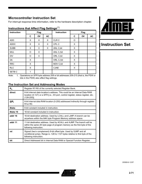
Table 1. AT89 <strong>Instruction</strong> <strong>Set</strong> Summary (1)Mnemonic Description Byte OscillatorPeriodARITHMETIC OPERATIONSMnemonic Description Byte OscillatorPeriodLOGICAL OPERATIONSADD A,R n Add register toAccumulator1 12ANL A,R n AND Register toAccumulator1 12ADD A,direct Add direct byte toAccumulator2 12ANL A,direct AND direct byte toAccumulator2 12ADD A,@R i Add indirect RAM toAccumulator1 12ANL A,@R i AND indirect RAM toAccumulator1 12ADD A,#data Add immediate data toAccumulator2 12ANL A,#data AND immediate data toAccumulator2 12ADDC A,R n Add register toAccumulator with Carry1 12ANL direct,A AND Accumulator todirect byte2 12ADDC A,direct Add direct byte toAccumulator with Carry2 12ANL direct,#data AND immediate data todirect byte3 24ADDC A,@R i Add indirect RAM toAccumulator with Carry1 12ORL A,R n OR register toAccumulator1 12ADDC A,#data Add immediate data toAcc with Carry2 12ORL A,direct OR direct byte toAccumulator2 12SUBB A,R n Subtract Register fromAcc with borrow1 12ORL A,@R i OR indirect RAM toAccumulator1 12SUBB A,direct Subtract direct byte fromAcc with borrow2 12ORL A,#data OR immediate data toAccumulator2 12SUBB A,@R i Subtract indirect RAMfrom ACC with borrow1 12ORL direct,A OR Accumulator to directbyte2 12SUBB A,#data Subtract immediate datafrom Acc with borrow2 12ORL direct,#data OR immediate data todirect byte3 24INC A Increment Accumulator 1 12INC R n Increment register 1 12INC direct Increment direct byte 2 12INC @R i Increment direct RAM 1 12DEC A Decrement Accumulator 1 12DEC R n Decrement Register 1 12DEC direct Decrement direct byte 2 12DEC @R i Decrement indirect RAM 1 12INC DPTR Increment Data Pointer 1 24MUL AB Multiply A & B 1 48DIV AB Divide A by B 1 48DA A Decimal AdjustAccumulator1 12Note: 1. All mnemonics copyrighted © Intel Corp., 1980.XRL A,R n Exclusive-OR register toAccumulatorXRL A,direct Exclusive-OR direct byteto AccumulatorXRL A,@R i Exclusive-OR indirectRAM to AccumulatorXRL A,#data Exclusive-OR immediatedata to AccumulatorXRL direct,A Exclusive-ORAccumulator to directbyteXRL direct,#data Exclusive-OR immediatedata to direct byte1 122 121 122 122 123 24CLR A Clear Accumulator 1 12CPL A ComplementAccumulator1 12RL A Rotate Accumulator Left 1 12RLC A Rotate Accumulator Leftthrough the Carry1 12LOGICAL OPERATIONS (continued)2-74<strong>Instruction</strong> <strong>Set</strong>
<strong>Instruction</strong> <strong>Set</strong>Mnemonic Description Byte OscillatorPeriodMnemonic Description Byte OscillatorPeriodRR A Rotate AccumulatorRight1 12MOVX A,@DPTR Move Exernal RAM (16-bit addr) to Acc1 24RRC A Rotate AccumulatorRight through the Carry1 12MOVX @R i ,A Move Acc to ExternalRAM (8-bit addr)1 24SWAP A Swap nibbles within theAccumulator1 12MOVX @DPTR,A Move Acc to ExternalRAM (16-bit addr)1 24DATA TRANSFERMOV A,R n Move register toAccumulatorMOV A,direct Move direct byte toAccumulatorMOV A,@R i Move indirect RAM toAccumulatorMOV A,#data Move immediate data toAccumulatorMOV R n ,A Move Accumulator toregisterMOV R n ,direct Move direct byte toregisterMOV R n ,#data Move immediate data toregister1 122 121 122 121 122 242 12PUSH direct Push direct byte ontostackPOP direct Pop direct byte fromstackXCH A,R n Exchange register withAccumulatorXCH A,direct Exchange direct bytewith AccumulatorXCH A,@R i Exchange indirect RAMwith AccumulatorXCHD A,@R i Exchange low-orderDigit indirect RAM withAccBOOLEAN VARIABLE MANIPULATION2 242 241 122 121 121 12CLR C Clear Carry 1 12MOV direct,A Move Accumulator todirect byteMOV direct,R n Move register to directbyte2 122 24MOV direct,direct Move direct byte to direct 3 24MOV direct,@R i Move indirect RAM todirect byteMOV direct,#data Move immediate data todirect byteMOV @R i ,A Move Accumulator toindirect RAMMOV @R i ,direct Move direct byte toindirect RAMMOV @R i ,#data Move immediate data toindirect RAMMOV DPTR,#data16 Load Data Pointer with a16-bit constantMOVC A,@A+DPTR Move Code byte relativeto DPTR to AccMOVC A,@A+PC Move Code byte relativeto PC to AccMOVX A,@R i Move External RAM (8-bit addr) to AccDATA TRANSFER (continued)2 243 241 122 242 123 241 241 241 24CLR bit Clear direct bit 2 12SETB C <strong>Set</strong> Carry 1 12SETB bit <strong>Set</strong> direct bit 2 12CPL C Complement Carry 1 12CPL bit Complement direct bit 2 12ANL C,bit AND direct bit to CARRY 2 24ANL C,/bit AND complement ofdirect bit to Carry2 24ORL C,bit OR direct bit to Carry 2 24ORL C,/bit OR complement of directbit to Carry2 24MOV C,bit Move direct bit to Carry 2 12MOV bit,C Move Carry to direct bit 2 24JC rel Jump if Carry is set 2 24JNC rel Jump if Carry not set 2 24JB bit,rel Jump if direct Bit is set 3 24JNB bit,rel Jump if direct Bit is NotsetJBC bit,rel Jump if direct Bit is set &clear bitPROGRAM BRANCHING3 243 242-75
Mnemonic Description Byte OscillatorPeriodACALL addr11 Absolute Subroutine Call 2 24LCALL addr16 Long Subroutine Call 3 24RET Return from Subroutine 1 24RETIReturn frominterrupt1 24AJMP addr11 Absolute Jump 2 24LJMP addr16 Long Jump 3 24SJMP rel Short Jump (relativeaddr)JMP @A+DPTR Jump indirect relative tothe DPTRJZ rel Jump if Accumulator isZeroJNZ rel Jump if Accumulator isNot ZeroCJNE A,direct,rel Compare direct byte toAcc and Jump if NotEqualCJNE A,#data,rel Compare immediate toAcc and Jump if NotEqualCJNE R n ,#data,rel Compare immediate toregister and Jump if NotEqualCJNE @R i ,#data,rel Compare immediate toindirect and Jump if NotEqualDJNZ R n ,rel Decrement register andJump if Not ZeroDJNZ direct,rel Decrement direct byteand Jump if Not Zero2 241 242 242 243 243 243 243 242 243 24NOP No Operation 1 122-76<strong>Instruction</strong> <strong>Set</strong>
<strong>Instruction</strong> <strong>Set</strong>Table 2. <strong>Instruction</strong> Opcodes in Hexadecimal OrderHexCodeNumberof Bytes00 1 NOPMnemonicOperands01 2 AJMP code addr02 3 LJMP code addr03 1 RR A04 1 INC A05 2 INC data addr06 1 INC @R007 1 INC @R108 1 INC R009 1 INC R10A 1 INC R20B 1 INC R30C 1 INC R40D 1 INC R50E 1 INC R60F 1 INC R710 3 JBC bit addr,code addr11 2 ACALL code addr12 3 LCALL code addr13 1 RRC A14 1 DEC A15 2 DEC data addr16 1 DEC @R017 1 DEC @R118 1 DEC R019 1 DEC R11A 1 DEC R21B 1 DEC R31C 1 DEC R41D 1 DEC R51E 1 DEC R61F 1 DEC R720 3 JB bit addr,code addr21 2 AJMP code addr22 1 RET23 1 RL A24 2 ADD A,#data25 2 ADD A,data addrHexCodeNumberof BytesMnemonicOperands26 1 ADD A,@R027 1 ADD A,@R128 1 ADD A,R029 1 ADD A,R12A 1 ADD A,R22B 1 ADD A,R32C 1 ADD A,R42D 1 ADD A,R52E 1 ADD A,R62F 1 ADD A,R730 3 JNB bit addr,code addr31 2 ACALL code addr32 1 RETI33 1 RLC A34 2 ADDC A,#data35 2 ADDC A,data addr36 1 ADDC A,@R037 1 ADDC A,@R138 1 ADDC A,R039 1 ADDC A,R13A 1 ADDC A,R23B 1 ADDC A,R33C 1 ADDC A,R43D 1 ADDC A,R53E 1 ADDC A,R63F 1 ADDC A,R740 2 JC code addr41 2 AJMP code addr42 2 ORL data addr,A43 3 ORL data addr,#data44 2 ORL A,#data45 2 ORL A,data addr46 1 ORL A,@R047 1 ORL A,@R148 1 ORL A,R049 1 ORL A,R14A 1 ORL A,R22-77
HexCodeNumberof BytesMnemonicOperandsHexCodeNumberof BytesMnemonicOperands4B 1 ORL A,R34C 1 ORL A,R44D 1 ORL A,R54E 1 ORL A,R64F 1 ORL A,R750 2 JNC code addr51 2 ACALL code addr52 2 ANL data addr,A53 3 ANL data addr,#data54 2 ANL A,#data55 2 ANL A,data addr56 1 ANL A,@R057 1 ANL A,@R158 1 ANL A,R059 1 ANL A,R15A 1 ANL A,R25B 1 ANL A,R35C 1 ANL A,R45D 1 ANL A,R55E 1 ANL A,R65F 1 ANL A,R760 2 JZ code addr61 2 AJMP code addr62 2 XRL data addr,A63 3 XRL data addr,#data64 2 XRL A,#data65 2 XRL A,data addr66 1 XRL A,@R067 1 XRL A,@R168 1 XRL A,R069 1 XRL A,R16A 1 XRL A,R26B 1 XRL A,R36C 1 XRL A,R46D 1 XRL A,R56E 1 XRL A,R66F 1 XRL A,R770 2 JNZ code addr71 2 ACALL code addr72 2 ORL C,bit addr73 1 JMP @A+DPTR74 2 MOV A,#data75 3 MOV data addr,#data76 2 MOV @R0,#data77 2 MOV @R1,#data78 2 MOV R0,#data79 2 MOV R1,#data7A 2 MOV R2,#data7B 2 MOV R3,#data7C 2 MOV R4,#data7D 2 MOV R5,#data7E 2 MOV R6,#data7F 2 MOV R7,#data80 2 SJMP code addr81 2 AJMP code addr82 2 ANL C,bit addr83 1 MOVC A,@A+PC84 1 DIV AB85 3 MOV data addr,data addr86 2 MOV data addr,@R087 2 MOV data addr,@R188 2 MOV data addr,R089 2 MOV data addr,R18A 2 MOV data addr,R28B 2 MOV data addr,R38C 2 MOV data addr,R48D 2 MOV data addr,R58E 2 MOV data addr,R68F 2 MOV data addr,R790 3 MOV DPTR,#data91 2 ACALL code addr92 2 MOV bit addr,C93 1 MOVC A,@A+DPTR94 2 SUBB A,#data95 2 SUBB A,data addr96 1 SUBB A,@R02-78<strong>Instruction</strong> <strong>Set</strong>
<strong>Instruction</strong> <strong>Set</strong>HexCodeNumberof BytesMnemonicOperandsHexCodeNumberof BytesMnemonicOperands97 1 SUBB A,@R198 1 SUBB A,R099 1 SUBB A,R19A 1 SUBB A,R29B 1 SUBB A,R39C 1 SUBB A,R49D 1 SUBB A,R59E 1 SUBB A,R69F 1 SUBB A,R7A0 2 ORL C,/bit addrA1 2 AJMP code addrA2 2 MOV C,bit addrA3 1 INC DPTRA4 1 MUL ABBD 3 CJNE R5,#data,code addrBE 3 CJNE R6,#data,code addrBF 3 CJNE R7,#data,code addrC0 2 PUSH data addrC1 2 AJMP code addrC2 2 CLR bit addrC3 1 CLR CC4 1 SWAP AC5 2 XCH A,data addrC6 1 XCH A,@R0C7 1 XCH A,@R1C8 1 XCH A,R0C9 1 XCH A,R1CA 1 XCH A,R2A5reservedCB 1 XCH A,R3A6 2 MOV @R0,data addrA7 2 MOV @R1,data addrA8 2 MOV R0,data addrA9 2 MOV R1,data addrAA 2 MOV R2,data addrAB 2 MOV R3,data addrAC 2 MOV R4,data addrAD 2 MOV R5,data addrAE 2 MOV R6,data addrAF 2 MOV R7,data addrB0 2 ANL C,/bit addrB1 2 ACALL code addrB2 2 CPL bit addrB3 1 CPL CB4 3 CJNE A,#data,code addrB5 3 CJNE A,data addr,code addrB6 3 CJNE @R0,#data,code addrB7 3 CJNE @R1,#data,code addrB8 3 CJNE R0,#data,code addrB9 3 CJNE R1,#data,code addrBA 3 CJNE R2,#data,code addrBB 3 CJNE R3,#data,code addrBC 3 CJNE R4,#data,code addrCC 1 XCH A,R4CD 1 XCH A,R5CE 1 XCH A,R6CF 1 XCH A,R7D0 2 POP data addrD1 2 ACALL code addrD2 2 SETB bit addrD3 1 SETB CD4 1 DA AD5 3 DJNZ data addr,code addrD6 1 XCHD A,@R0D7 1 XCHD A,@R1D8 2 DJNZ R0,code addrD9 2 DJNZ R1,code addrDA 2 DJNZ R2,code addrDB 2 DJNZ R3,code addrDC 2 DJNZ R4,code addrDD 2 DJNZ R5,code addrDE 2 DJNZ R6,code addrDF 2 DJNZ R7,code addrE0 1 MOVX A,@DPTRE1 2 AJMP code addrE2 1 MOVX A,@R02-79
HexCodeNumberof BytesMnemonicOperandsE3 1 MOVX A,@R1E4 1 CLR AE5 2 MOV A,data addrE6 1 MOV A,@R0E7 1 MOV A,@R1E8 1 MOV A,R0E9 1 MOV A,R1EA 1 MOV A,R2EB 1 MOV A,R3EC 1 MOV A,R4ED 1 MOV A,R5EE 1 MOV A,R6EF 1 MOV A,R7F0 1 MOVX @DPTR,AF1 2 ACALL code addrF2 1 MOVX @R0,AF3 1 MOVX @R1,AF4 1 CPL AF5 2 MOV data addr,AF6 1 MOV @R0,AF7 1 MOV @R1,AF8 1 MOV R0,AF9 1 MOV R1,AFA 1 MOV R2,AFB 1 MOV R3,AFC 1 MOV R4,AFD 1 MOV R5,AFE 1 MOV R6,AFF 1 MOV R7,A2-80<strong>Instruction</strong> <strong>Set</strong>
<strong>Instruction</strong> <strong>Set</strong><strong>Instruction</strong> DefinitionsACALL addr11Function: Absolute CallDescription: ACALL unconditionally calls a subroutine located at the indicated address. The instruction increments the PCtwice to obtain the address of the following instruction, then pushes the 16-bit result onto the stack (low-orderbyte first) and increments the Stack Pointer twice. The destination address is obtained by successivelyconcatenating the five high-order bits of the incremented PC, opcode bits 7 through 5, and the second byte of theinstruction. The subroutine called must therefore start within the same 2 K block of the program memory as thefirst byte of the instruction following ACALL. No flags are affected.Example: Initially SP equals 07H. The label SUBRTN is at program memory location 0345 H. After executing the followinginstruction,Bytes: 2Cycles: 2ACALLSUBRTNat location 0123H, SP contains 09H, internal RAM locations 08H and 09H will contain 25H and 01H, respectively,and the PC contains 0345H.Encoding: a10 a9 a8 1 0 0 0 1 a7 a6 a5 a4 a3 a2 a1 a0Operation: ACALL(PC) ← (PC) + 2(SP) ← (SP) + 1((SP)) ← (PC 7-0 )(SP) ← (SP) + 1((SP)) ← (PC 15-8 )(PC 10-0 ) ← page address2-81
ADD A,R nBytes: 1ADD A,@R iBytes: 1ADDA,Function: AddDescription: ADD adds the byte variable indicated to the Accumulator, leaving the result in the Accumulator. The carry andauxiliary-carry flags are set, respectively, if there is a carry-out from bit 7 or bit 3, and cleared otherwise. Whenadding unsigned integers, the carry flag indicates an overflow occurred.OV is set if there is a carry-out of bit 6 but not out of bit 7, or a carry-out of bit 7 but not bit 6; otherwise, OV iscleared. When adding signed integers, OV indicates a negative number produced as the sum of two positiveoperands, or a positive sum from two negative operands.Four source operand addressing modes are allowed: register, direct, register-indirect, or immediate.Example: The Accumulator holds 0C3H (1100001lB), and register 0 holds 0AAH (10101010B). The following instruction,ADDA,R0leaves 6DH (01101101B) in the Accumulator with the AC flag cleared and both the carry flag and OV set to 1.ADD A,directCycles: 1Encoding: 0 0 1 0 1 r r rOperation: ADD(A) ← (A) + (R n )Bytes: 2Cycles: 1Encoding: 0 0 1 0 0 1 0 1 direct addressOperation: ADD(A) ← (A) + (direct)ADD A,#dataCycles: 1Encoding: 0 0 1 0 0 1 1 iOperation: ADD(A) ← (A) + ((R i ))Bytes: 2Cycles: 1Encoding: 0 0 1 0 0 1 0 0 immediate dataOperation: ADD(A) ← (A) + #data2-82<strong>Instruction</strong> <strong>Set</strong>
ADDC A,R nBytes: 1<strong>Instruction</strong> <strong>Set</strong>ADDC A, Function: Add with CarryDescription: ADDC simultaneously adds the byte variable indicated, the carry flag and the Accumulator contents, leaving theresult in the Accumulator. The carry and auxiliary-carry flags are set respectively, if there is a carry-out from bit 7or bit 3, and cleared otherwise. When adding unsigned integers, the carry flag indicates an overflow occurred.OV is set if there is a carry-out of bit 6 but not out of bit 7, or a carry-out of bit 7 but not out of bit 6; otherwise OVis cleared. When adding signed integers, OV indicates a negative number produced as the sum of two positiveoperands or a positive sum from two negative operands.Four source operand addressing modes are allowed: register, direct, register-indirect, or immediate.Example: The Accumulator holds 0C3H (11000011B) and register 0 holds 0AAH (10101010B) with the carry flag set. Thefollowing instruction,ADDCA,R0leaves 6EH (01101110B) in the Accumulator with AC cleared and both the Carry flag and OV set to 1.ADDC A,directADDC A,@R iADDC A,#dataCycles: 1Encoding: 0 0 1 1 1 r r rOperation: ADDC(A) ← (A) + (C) + (R n )Bytes: 2Cycles: 1Encoding: 0 0 1 1 0 1 0 1 direct addressOperation: ADDC(A) ← (A) + (C) + (direct)Bytes: 1Cycles: 1Encoding: 0 0 1 1 0 1 1 iOperation: ADDC(A) ← (A) + (C) + ((R i ))Bytes: 2Cycles: 1Encoding: 0 0 1 1 0 1 0 0 immediate dataOperation: ADDC(A) ← (A) + (C) + #data2-83
ANL A,R nBytes: 1AJMPaddr11Function: Absolute JumpDescription: AJMP transfers program execution to the indicated address, which is formed at run-time by concatenating thehigh-order five bits of the PC (after incrementing the PC twice), opcode bits 7 through 5, and the second byte ofthe instruction. The destination must therfore be within the same 2 K block of program memory as the first byte ofthe instruction following AJMP.Example: The label JMPADR is at program memory location 0123H. The following instruction,Bytes: 2Cycles: 2AJMPJMPADRis at location 0345H and loads the PC with 0123H.Encoding: a10 a9 a8 0 0 0 0 1 a7 a6 a5 a4 a3 a2 a1 a0Operation: AJMP(PC) ← (PC) + 2(PC 10-0 ) ← page addressANL,Function: Logical-AND for byte variablesDescription: ANL performs the bitwise logical-AND operation between the variables indicated and stores the results in thedestination variable. No flags are affected.The two operands allow six addressing mode combinations. When the destination is the Accumulator, the sourcecan use register, direct, register-indirect, or immediate addressing; when the destination is a direct address, thesource can be the Accumulator or immediate data.Note: When this instruction is used to modify an output port, the value used as the original port data will be readfrom the output data latch, not the input pins.Example: If the Accumulator holds 0C3H (1100001lB), and register 0 holds 55H (01010101B), then the followinginstruction,ANLA,R0leaves 41H (01000001B) in the Accumulator.When the destination is a directly addressed byte, this instruction clears combinations of bits in any RAMlocation or hardware register. The mask byte determining the pattern of bits to be cleared would either be aconstant contained in the instruction or a value computed in the Accumulator at run-time. The followinginstruction,ANLP1,#01110011Bclears bits 7, 3, and 2 of output port 1.Cycles: 1Encoding: 0 1 0 1 1 r r rOperation: ANL(A) ← (A) ∧ (R n )2-84<strong>Instruction</strong> <strong>Set</strong>
<strong>Instruction</strong> <strong>Set</strong>ANLANLANLANLANLA,directBytes: 2Cycles: 1Encoding: 0 1 0 1 0 1 0 1 direct addressOperation: ANL(A) ← (A) ∧ (direct)A,@R iBytes: 1Cycles: 1Encoding: 0 1 0 1 0 1 1 iOperation: ANL(A) ← (A) ∧ ((R i ))A,#dataBytes: 2Cycles: 1Encoding: 0 1 0 1 0 1 0 0 immediate dataOperation: ANL(A) ← (A) ∧ #datadirect,ABytes: 2Cycles: 1Encoding: 0 1 0 1 0 0 1 0 direct addressOperation: ANL(direct) ← (direct) ∧ (A)direct,#dataBytes: 3Cycles: 2Encoding: 0 1 0 1 0 0 1 1 direct address immediate dataOperation: ANL(direct) ← (direct) ∧ #data2-85
ANLANLANLC,Function: Logical-AND for bit variablesDescription: If the Boolean value of the source bit is a logical 0, then ANL C clears the carry flag; otherwise, this instructionleaves the carry flag in its current state. A slash ( / ) preceding the operand in the assembly language indicatesthat the logical complement of the addressed bit is used as the source value, but the source bit itself is notaffected. No other flags are affected.Only direct addressing is allowed for the source operand.Example: <strong>Set</strong> the carry flag if, and only if, P1.0 = 1, ACC.7 = 1, and OV = 0:C,bitBytes: 2Cycles: 2MOV C,P1.0 ;LOAD CARRY WITH INPUT PIN STATEANL C,ACC.7 ;AND CARRY WITH ACCUM. BIT 7ANL C,/OV ;AND WITH INVERSE OF OVERFLOW FLAGEncoding: 1 0 0 0 0 0 1 0 bit addressOperation: ANL(C) ← (C) ∧ (bit)C,/bitBytes: 2Cycles: 2Encoding: 1 0 1 1 0 0 0 0 bit addressOperation: ANL(C) ← (C) ∧(bit)2-86<strong>Instruction</strong> <strong>Set</strong>
<strong>Instruction</strong> <strong>Set</strong>CJNE,, relFunction: Compare and Jump if Not Equal.Description: CJNE compares the magnitudes of the first two operands and branches if their values are not equal. The branchdestination is computed by adding the signed relative-displacement in the last instruction byte to the PC, afterincrementing the PC to the start of the next instruction. The carry flag is set if the unsigned integer value of is less than the unsigned integer value of ; otherwise, the carry is cleared. Neitheroperand is affected.CJNE A,direct,relThe first two operands allow four addressing mode combinations: the Accumulator may be compared with anydirectly addressed byte or immediate data, and any indirect RAM location or working register can be comparedwith an immediate constant.Example: The Accumulator contains 34H. Register 7 contains 56H. The first instruction in the sequence,Bytes: 3Cycles: 2CJNER7, # 60H, NOT_EQ; . . . . . . . . ;R7 = 60H.NOT_EQ: JC REQ_LOW ;IF R7 < 60H.; . . . . . . . . ;R7 > 60H.sets the carry flag and branches to the instruction at label NOT_EQ. By testing the carry flag, this instructiondetermines whether R7 is greater or less than 60H.If the data being presented to Port 1 is also 34H, then the following instruction,WAIT: CJNE A, P1,WAITclears the carry flag and continues with the next instruction in sequence, since the Accumulator does equal thedata read from P1. (If some other value was being input on P1, the program loops at this point until the P1 datachanges to 34H.)Encoding: 1 0 1 1 0 1 0 1 direct address rel. addressOperation: (PC) ← (PC) + 3IF (A) < > (direct)THEN(PC) ← (PC) + relative offsetIF (A) < (direct)THEN(C) ← 1ELSE(C) ← 02-87
CJNE A,#data,relBytes: 3Cycles: 2Encoding: 1 0 1 1 0 1 0 0 immediate data rel. addressOperation: (PC) ← (PC) + 3IF (A) < > dataTHEN(PC) ← (PC) + relative offsetIF (A) < dataTHEN(C) ← 1ELSE(C) ← 0CJNE R n ,#data,relBytes: 3Cycles: 2Encoding: 1 0 1 1 1 r r r immediate data rel. addressOperation: (PC) ← (PC) + 3IF (R n ) < > dataTHEN(PC) ← (PC) + relative offsetIF (R n ) < dataTHEN(C) ← 1ELSE(C) ← 0CJNE @R i ,data,relBytes: 3Cycles: 2Encoding: 1 0 1 1 0 1 1 i immediate data rel. addressOperation: (PC) ← (PC) + 3IF ((R i )) < > dataTHEN(PC) ← (PC) + relative offsetIF ((R i )) < dataTHEN(C) ← 1ELSE(C) ← 02-88<strong>Instruction</strong> <strong>Set</strong>
<strong>Instruction</strong> <strong>Set</strong>CLRCLRCLRCLRAFunction: Clear AccumulatorDescription: CLR A clears the Accumulator (all bits set to 0). No flags are affectedExample: The Accumulator contains 5CH (01011100B). The following instruction,CLR Aleaves the Accumulator set to 00H(00000000B).bitBytes: 1Cycles: 1Encoding: 1 1 1 0 0 1 0 0Operation: CLR(A) ← 0Function: Clear bitDescription: CLR bit clears the indicated bit (reset to 0). No other flags are affected. CLR can operate on the carry flag or anydirectly addressable bit.CExample: Port 1 has previously been written with 5DH (01011101B). The following instruction,CLR P1.2 leaves the port setto 59H (01011001B).Bytes: 1Cycles: 1Encoding: 1 1 0 0 0 0 1 1Operation: CLR(C) ← 0bitBytes: 2Cycles: 1Encoding: 1 1 0 0 0 0 1 0 bit addressOperation: CLR(bit) ← 02-89
CPLCPLCPLAFunction: Complement AccumulatorDescription: CPLA logically complements each bit of the Accumulator (one’s complement). Bits which previously contained a1 are changed to a 0 and vice-versa. No flags are affected.Example: The Accumulator contains 5CH (01011100B). The following instruction,bitBytes: 1Cycles: 1CPLAleaves the Accumulator set to 0A3H (10100011B).Encoding: 1 1 1 1 0 1 0 0Operation: CPL(A) ←(A)Function: Complement bitDescription: CPL bit complements the bit variable specified. A bit that had been a 1 is changed to 0 and vice-versa. No otherflags are affected. CLR can operate on the carry or any directly addressable bit.CNote: When this instruction is used to modify an output pin, the value used as the original data is read from theoutput data latch, not the input pin.Example: Port 1 has previously been written with 5BH (01011101B). The following instruction sequence,CPL P1.1CPLP1.2 leaves the port set to 5BH (01011011B).Bytes: 1Cycles: 1Encoding: 1 0 1 1 0 0 1 1Operation: CPL(C) ←(C)CPLbitBytes: 2Cycles: 1Encoding: 1 0 1 1 0 0 1 0 bit addressOperation: CPL(bit) ←(bit)2-90<strong>Instruction</strong> <strong>Set</strong>
<strong>Instruction</strong> <strong>Set</strong>DAAFunction: Decimal-adjust Accumulator for AdditionDescription: DA A adjusts the eight-bit value in the Accumulator resulting from the earlier addition of two variables (each inpacked-BCD format), producing two four-bit digits. Any ADD or ADDC instruction may have been used toperform the addition.If Accumulator bits 3 through 0 are greater than nine (xxxx1010-xxxx1111), or if the AC flag is one, six is addedto the Accumulator producing the proper BCD digit in the low-order nibble. This internal addition sets the carryflag if a carry-out of the low-order four-bit field propagates through all high-order bits, but it does not clear thecarry flag otherwise.If the carry flag is now set, or if the four high-order bits now exceed nine (1010xxxx-1111xxxx), these high-orderbits are incremented by six, producing the proper BCD digit in the high-order nibble. Again, this sets the carryflag if there is a carry-out of the high-order bits, but does not clear the carry. The carry flag thus indicates if thesum of the original two BCD variables is greater than 100, allowing multiple precision decimal addition. OV is notaffected.All of this occurs during the one instruction cycle. Essentially, this instruction performs the decimal conversion byadding 00H, 06H, 60H, or 66H to the Accumulator, depending on initial Accumulator and PSW conditions.Note: DA A cannot simply convert a hexadecimal number in the Accumulator to BCD notation, nor does DAAapply to decimal subtraction.Example: The Accumulator holds the value 56H (01010110B), representing the packed BCD digits of the decimal number56. Register 3 contains the value 67H (01100111B), representing the packed BCD digits of the decimal number67. The carry flag is set. The following instruction sequenceBytes: 1Cycles: 1ADDCDAA,R3Afirst performs a standard two’s-complement binary addition, resulting in the value 0BEH (10111110) in theAccumulator. The carry and auxiliary carry flags are cleared.The Decimal Adjust instruction then alters the Accumulator to the value 24H (00100100B), indicating the packedBCD digits of the decimal number 24, the low-order two digits of the decimal sum of 56, 67, and the carry-in. Thecarry flag is set by the Decimal Adjust instruction, indicating that a decimal overflow occurred. The true sum of56, 67, and 1 is 124.BCD variables can be incremented or decremented by adding 01H or 99H. If the Accumulator initially holds 30H(representing the digits of 30 decimal), then the following instruction sequence,ADDDAA, # 99HAleaves the carry set and 29H in the Accumulator, since 30 + 99 = 129. The low-order byte of the sum can beinterpreted to mean 30 - 1 = 29.Encoding: 1 1 0 1 0 1 0 0Operation: DA-contents of Accumulator are BCDIF [[(A 3-0 ) > 9] ∨ [(AC) = 1]]THEN (A 3-0 ) ← (A 3-0 ) + 6ANDIF [[(A 7-4 ) > 9] ∨ [(C) = 1]]THEN (A 7-4 ) ← (A 7-4 ) + 62-91
DEC R nBytes: 1DEC @R iBytes: 1DECDECbyteFunction: DecrementDescription: DEC byte decrements the variable indicated by 1. An original value of 00H underflows to 0FFH. No flags areaffected. Four operand addressing modes are allowed: accumulator, register, direct, or register-indirect.ANote: When this instruction is used to modify an output port, the value used as the original port data will be readfrom the output data latch, not the input pins.Example: Register 0 contains 7FH (01111111B). Internal RAM locations 7EH and 7FH contain 00H and 40H, respectively.The following instruction sequence,Bytes: 1Cycles: 1DECDECDEC@R0R0@R0leaves register 0 set to 7EH and internal RAM locations 7EH and 7FH set to 0FFH and 3FH.Encoding: 0 0 0 1 0 1 0 0Operation: DEC(A) ← (A) - 1Cycles: 1Encoding: 0 0 0 1 1 r r rDECOperation: DEC(R n ) ← (R n ) - 1directBytes: 2Cycles: 1Encoding: 0 0 0 1 0 1 0 1 direct addressOperation: DEC(direct) ← (direct) - 1Cycles: 1Encoding: 0 0 0 1 0 1 1 iOperation: DEC((R i )) ← ((R i )) - 12-92<strong>Instruction</strong> <strong>Set</strong>
<strong>Instruction</strong> <strong>Set</strong>DIVABFunction: DivideDescription: DIV AB divides the unsigned eight-bit integer in the Accumulator by the unsigned eight-bit integer in register B.The Accumulator receives the integer part of the quotient; register B receives the integer remainder. The carryand OV flags are cleared.Exception: if B had originally contained 00H, the values returned in the Accumulator and B-register areundefined and the overflow flag are set. The carry flag is cleared in any case.Example: The Accumulator contains 251 (0FBH or 11111011B) and B contains 18 (12H or 00010010B). The followinginstruction,Bytes: 1Cycles: 4DIVABleaves 13 in the Accumulator (0DH or 00001101B) and the value 17 (11H or 00010001B) in B, since251 = (13 x 18) + 17. Carry and OV are both cleared.Encoding: 1 0 0 0 0 1 0 0Operation: DIV(A) 15-8 ← (A)/(B)(B) 7-02-93
DJNZDJNZ R n ,rel,Function: Decrement and Jump if Not ZeroDescription: DJNZ decrements the location indicated by 1, and branches to the address indicated by the second operand ifthe resulting value is not zero. An original value of 00H underflows to 0FFH. No flags are affected. The branchdestination is computed by adding the signed relative-displacement value in the last instruction byte to the PC,after incrementing the PC to the first byte of the following instruction.The location decremented may be a register or directly addressed byte.Note: When this instruction is used to modify an output port, the value used as the original port data will be readfrom the output data latch, not the input pins.Example: Internal RAM locations 40H, 50H, and 60H contain the values 01H, 70H, and 15H, respectively. The followinginstruction sequence,Bytes: 2Cycles: 2DJNZ direct,relDJNZDJNZDJNZ40H,LABEL_150H,LABEL_260H,LABEL_3causes a jump to the instruction at label LABEL_2 with the values 00H, 6FH, and 15H in the three RAMlocations. The first jump was not taken because the result was zero.This instruction provides a simple way to execute a program loop a given number of times or for adding amoderate time delay (from 2 to 512 machine cycles) with a single instruction. The following instruction sequence,MOV R2, # 8TOGGLE: CPL P1.7DJNZR2,TOGGLEtoggles P1.7 eight times, causing four output pulses to appear at bit 7 of output Port 1. Each pulse lasts threemachine cycles; two for DJNZ and one to alter the pin.Encoding: 1 1 0 1 1 r r r rel. addressOperation: DJNZ(PC) ← (PC) + 2(R n ) ← (R n ) - 1IF (R n ) > 0 or (R n ) < 0THEN(PC) ← (PC) + relBytes: 3Cycles: 2Encoding: 1 1 0 1 0 1 0 1 direct address rel. addressOperation: DJNZ(PC) ← (PC) + 2(direct) ← (direct) - 1IF (direct) > 0 or (direct) < 0THEN(PC) ← (PC) + rel2-94<strong>Instruction</strong> <strong>Set</strong>
INC R nBytes: 1INC @R iBytes: 1<strong>Instruction</strong> <strong>Set</strong>INCINCFunction: IncrementDescription: INC increments the indicated variable by 1. An original value of 0FFH overflows to 00H. No flags are affected.Three addressing modes are allowed: register, direct, or register-indirect.ANote: When this instruction is used to modify an output port, the value used as the original port data will be readfrom the output data latch, not the input pins.Example: Register 0 contains 7EH (011111110B). Internal RAM locations 7EH and 7FH contain 0FFH and 40H,respectively. The following instruction sequence,Bytes: 1Cycles: 1INCINCINC@R0R0@R0leaves register 0 set to 7FH and internal RAM locations 7EH and 7FH holding 00H and 41H, respectively.Encoding: 0 0 0 0 0 1 0 0Operation: INC(A) ← (A) + 1Cycles: 1Encoding: 0 0 0 0 1 r r rINCOperation: INC(R n ) ← (R n ) + 1directBytes: 2Cycles: 1Encoding: 0 0 0 0 0 1 0 1 direct addressOperation: INC(direct) ← (direct) + 1Cycles: 1Encoding: 0 0 0 0 0 1 1 iOperation: INC((R i )) ← ((R i )) + 12-95
INCJBDPTRFunction: Increment Data PointerDescription: INC DPTR increments the 16-bit data pointer by 1. A 16-bit increment (modulo 2 16 ) is performed, and anoverflow of the low-order byte of the data pointer (DPL) from 0FFH to 00H increments the high-order byte (DPH).No flags are affected.blt,relThis is the only 16-bit register which can be incremented.Example: Registers DPH and DPL contain 12H and 0FEH, respectively. The following instruction sequence,Bytes: 1Cycles: 2INCINCINCDPTRDPTRDPTRchanges DPH and DPL to 13H and 01H.Encoding: 1 0 1 0 0 0 1 1Operation: INC(DPTR) ← (DPTR) + 1Function: Jump if Bit setDescription: If the indicated bit is a one, JB jump to the address indicated; otherwise, it proceeds with the next instruction. Thebranch destination is computed by adding the signed relative-displacement in the third instruction byte to the PC,after incrementing the PC to the first byte of the next instruction. The bit tested is not modified. No flags areaffected.Example: The data present at input port 1 is 11001010B. The Accumulator holds 56 (01010110B). The following instructionsequence,Bytes: 3Cycles: 2JBJBP1.2,LABEL1ACC. 2,LABEL2causes program execution to branch to the instruction at label LABEL2.Encoding: 0 0 1 0 0 0 0 0 bit address rel. addressOperation: JB(PC) ← (PC) + 3IF (bit) = 1THEN(PC) ← (PC) + rel2-96<strong>Instruction</strong> <strong>Set</strong>
<strong>Instruction</strong> <strong>Set</strong>JBCJCbit,relFunction: Jump if Bit is set and Clear bitDescription: If the indicated bit is one, JBC branches to the address indicated; otherwise, it proceeds with the next instruction.The bit will not be cleared if it is already a zero. The branch destination is computed by adding the signedrelative-displacement in the third instruction byte to the PC, after incrementing the PC to the first byte of the nextinstruction. No flags are affected.relNote: When this instruction is used to test an output pin, the value used as the original data will be read from theoutput data latch, not the input pin.Example: The Accumulator holds 56H (01010110B). The following instruction sequence,Bytes: 3Cycles: 2JBCJBCACC.3,LABEL1ACC.2,LABEL2causes program execution to continue at the instruction identified by the label LABEL2, with the Accumulatormodified to 52H (01010010B).Encoding: 0 0 0 1 0 0 0 0 bit address rel. addressOperation: JBC(PC) ← (PC) + 3IF (bit) = 1THEN(bit) ← 0(PC) ← (PC) +relFunction: Jump if Carry is setDescription: If the carry flag is set, JC branches to the address indicated; otherwise, it proceeds with the next instruction. Thebranch destination is computed by adding the signed relative-displacement in the second instruction byte to thePC, after incrementing the PC twice. No flags are affected.Example: The carry flag is cleared. The following instruction sequence,Bytes: 2Cycles: 2JCCPLLABEL1CJC LABEL 2sets the carry and causes program execution to continue at the instruction identified by the label LABEL2.Encoding: 0 1 0 0 0 0 0 0 rel. addressOperation: JC(PC) ← (PC) + 2IF (C) = 1THEN(PC) ← (PC) + rel2-97
JMP@A+DPTRFunction: Jump indirectDescription: JMP @A+DPTR adds the eight-bit unsigned contents of the Accumulator with the 16-bit data pointer and loadsthe resulting sum to the program counter. This is the address for subsequent instruction fetches. Sixteen-bitaddition is performed (modulo 2 16 ): a carry-out from the low-order eight bits propagates through the higher-orderbits. Neither the Accumulator nor the Data Pointer is altered. No flags are affected.Example: An even number from 0 to 6 is in the Accumulator. The following sequence of instructions branches to one of fourAJMP instructions in a jump table starting at JMP_TBL.Bytes: 1Cycles: 2MOVJMPDPTR, # JMP_TBL@A + DPTRJMP_TBL: AJMP LABEL0AJMPAJMPAJMPLABEL1LABEL2LABEL3If the Accumulator equals 04H when starting this sequence, execution jumps to label LABEL2. Because AJMP isa 2-byte instruction, the jump instructions start at every other address.Encoding: 0 1 1 1 0 0 1 1Operation: JMP(PC) ← (A) + (DPTR)2-98<strong>Instruction</strong> <strong>Set</strong>
<strong>Instruction</strong> <strong>Set</strong>JNB bit,relFunction: Jump if Bit Not setDescription: If the indicated bit is a 0, JNB branches to the indicated address; otherwise, it proceeds with the next instruction.The branch destination is computed by adding the signed relative-displacement in the third instruction byte to thePC, after incrementing the PC to the first byte of the next instruction. The bit tested is not modified. No flags areaffected.Example: The data present at input port 1 is 11001010B. The Accumulator holds 56H (01010110B). The followinginstruction sequence,Bytes: 3Cycles: 2JNBJNBP1.3,LABEL1ACC.3,LABEL2causes program execution to continue at the instruction at label LABEL2.Encoding: 0 0 1 1 0 0 0 0 bit address rel. addressOperation: JNB(PC) ← (PC) + 3IF (bit) = 0THEN (PC) ← (PC) + relJNCrelFunction: Jump if Carry not setDescription: If the carry flag is a 0, JNC branches to the address indicated; otherwise, it proceeds with the next instruction.The branch destination is computed by adding the signal relative-displacement in the second instruction byte tothe PC, after incrementing the PC twice to point to the next instruction. The carry flag is not modified.Example: The carry flag is set. The following instruction sequence,Bytes: 2Cycles: 2JNCCPLJNCLABEL1CLABEL2clears the carry and causes program execution to continue at the instruction identified by the label LABEL2.Encoding: 0 1 0 1 0 0 0 0 rel. addressOperation: JNC(PC) ← (PC) + 2IF (C) = 0THEN (PC) ← (PC) + rel2-99
JNZJZrelFunction: Jump if Accumulator Not ZeroDescription: If any bit of the Accumulator is a one, JNZ branches to the indicated address; otherwise, it proceeds with the nextinstruction. The branch destination is computed by adding the signed relative-displacement in the secondinstruction byte to the PC, after incrementing the PC twice. The Accumulator is not modified. No flags areaffected.Example: The Accumulator originally holds 00H. The following instruction sequence,relBytes: 2Cycles: 2JNZINCJNZLABEL1ALABEL2sets the Accumulator to 01H and continues at label LABEL2.Encoding: 0 1 1 1 0 0 0 0 rel. addressOperation: JNZ(PC) ← (PC) + 2IF (A) ≠ 0THEN (PC) ← (PC) + relFunction: Jump if Accumulator ZeroDescription: If all bits of the Accumulator are 0, JZ branches to the address indicated; otherwise, it proceeds with the nextinstruction. The branch destination is computed by adding the signed relative-displacement in the secondinstruction byte to the PC, after incrementing the PC twice. The Accumulator is not modified. No flags areaffected.Example: The Accumulator originally contains 01H. The following instruction sequence,JZDECJZBytes: 2Cycles: 2LABEL1ALABEL2changes the Accumulator to 00H and causes program execution to continue at the instruction identified by thelabel LABEL2.Encoding: 0 1 1 0 0 0 0 0 rel. addressOperation: JZ(PC) ← (PC) + 2IF (A) = 0THEN (PC) ← (PC) + rel2-100<strong>Instruction</strong> <strong>Set</strong>
<strong>Instruction</strong> <strong>Set</strong>LCALL addr16LJMPFunction: Long callDescription: LCALL calls a subroutine located at the indicated address. The instruction adds three to the program counter togenerate the address of the next instruction and then pushes the 16-bit result onto the stack (low byte first),incrementing the Stack Pointer by two. The high-order and low-order bytes of the PC are then loaded,respectively, with the second and third bytes of the LCALL instruction. Program execution continues with theinstruction at this address. The subroutine may therefore begin anywhere in the full 64K byte program memoryaddress space. No flags are affected.Example: Initially the Stack Pointer equals 07H. The label SUBRTN is assigned to program memory location 1234H. Afterexecuting the instruction,Bytes: 3Cycles: 2addr16LCALLSUBRTNat location 0123H, the Stack Pointer will contain 09H, internal RAM locations 08H and 09H will contain 26H and01H, and the PC will contain 1234H.Encoding: 0 0 0 1 0 0 1 0 addr15-addr8 addr7-addr0Operation: LCALL(PC) ← (PC) + 3(SP) ← (SP) + 1((SP)) ← (PC 7-0 )(SP) ← (SP) + 1((SP)) ← (PC 15-8 )(PC) ← addr 15-0Function: Long JumpDescription: LJMP causes an unconditional branch to the indicated address, by loading the high-order and low-order bytes ofthe PC (respectively) with the second and third instruction bytes. The destination may therefore be anywhere inthe full 64K program memory address space. No flags are affected.Example: The label JMPADR is assigned to the instruction at program memory location 1234H. The instruction,Bytes: 3Cycles: 2LJMPJMPADRat location 0123H will load the program counter with 1234H.Encoding: 0 0 0 0 0 0 1 0 addr15-addr8 addr7-addr0Operation: LJMP(PC) ← addr 15-02-101
MOV A,R nBytes: 1MOV ,Function: Move byte variableDescription: The byte variable indicated by the second operand is copied into the location specified by the first operand. Thesource byte is not affected. No other register or flag is affected.This is by far the most flexible operation. Fifteen combinations of source and destination addressing modes areallowed.Example: Internal RAM location 30H holds 40H. The value of RAM location 40H is 10H. The data present at input port 1 is11001010B (0CAH).MOV R0,#30H ;R0 < = 30HMOV A,@R0 ;A < = 40HMOV R1,A ;R1 < = 40HMOV B,@R1 ;B < = 10HMOV @R1,P1 ;RAM (40H) < = 0CAHMOV P2,P1 ;P2 #0CAHleaves the value 30H in register 0, 40H in both the Accumulator and register 1, 10H in register B, and 0CAH(11001010B) both in RAM location 40H and output on port 2.*MOV A,directCycles: 1Encoding: 1 1 1 0 1 r r rOperation: MOV(A) ← (R n )Bytes: 2Cycles: 1Encoding: 1 1 1 0 0 1 0 1 direct addressOperation: MOV(A) ← (direct)* MOV A,ACC is not a valid <strong>Instruction</strong>.MOV A,@R iBytes: 1Cycles: 1Encoding: 1 1 1 0 0 1 1 iOperation: MOV(A) ← ((R i ))2-102<strong>Instruction</strong> <strong>Set</strong>
<strong>Instruction</strong> <strong>Set</strong>MOVA,#dataMOV R n ,AMOVMOVMOVMOVBytes: 2Cycles: 1Encoding: 0 1 1 1 0 1 0 0 immediate dataOperation: MOV(A) ← #dataBytes: 1Cycles: 1Encoding: 1 1 1 1 1 r r rOperation: MOV(R n ) ← (A)R n ,directBytes: 2Cycles: 2Encoding: 1 0 1 0 1 r r r direct addr.Operation: MOV(R n ) ← (direct)R n ,#dataBytes: 2Cycles: 1Encoding: 0 1 1 1 1 r r r immediate dataOperation: MOV(R n ) ← #datadirect,ABytes: 2Cycles: 1Encoding: 1 1 1 1 0 1 0 1 direct addressOperation: MOV(direct) ← (A)direct,R nBytes: 2Cycles: 2Encoding: 1 0 0 0 1 r r r direct addressOperation: MOV(direct) ← (R n )2-103
MOVMOVMOVdirect,directBytes: 3Cycles: 2Encoding: 1 0 0 0 0 1 0 1 dir. addr. (scr) dir. addr. (dest)Operation: MOV(direct) ← (direct)direct,@R iBytes: 2Cycles: 2Encoding: 1 0 0 0 0 1 1 i direct addr.Operation: MOV(direct) ← ((R i ))direct,#dataMOV @R i ,AMOVMOVBytes: 3Cycles: 2Encoding: 0 1 1 1 0 1 0 1 direct address immediate dataOperation: MOV(direct) ← #dataBytes: 1Cycles: 1Encoding: 1 1 1 1 0 1 1 iOperation: MOV((R i )) ← (A)@R i ,directBytes: 2Cycles: 2Encoding: 1 0 1 0 0 1 1 i direct addr.Operation: MOV((R i )) ← (direct)@R i ,#dataBytes: 2Cycles: 1Encoding: 0 1 1 1 0 1 1 i immediate dataOperation: MOV((R i )) ← #data2-104<strong>Instruction</strong> <strong>Set</strong>
<strong>Instruction</strong> <strong>Set</strong>MOVMOVMOVMOV,Function: Move bit dataDescription: MOV , copies the Boolean variable indicated by the second operand into the locationspecified by the first operand. One of the operands must be the carry flag; the other may be any directlyaddressable bit. No other register or flag is affected.Example: The carry flag is originally set. The data present at input Port 3 is 11000101B. The data previously written tooutput Port 1 is 35H (00110101B).C,bitBytes: 2Cycles: 1MOVMOVMOVDPTR,#data16P1.3,CC,P3.3P1.2,Cleaves the carry cleared and changes Port 1 to 39H (00111001B).Encoding: 1 0 1 0 0 0 1 0 bit addressOperation: MOV(C) ← (bit)bit,CBytes: 2Cycles: 2Encoding: 1 0 0 1 0 0 1 0 bit addressOperation: MOV(bit) ← (C)Function: Load Data Pointer with a 16-bit constantDescription: MOV DPTR,#data16 loads the Data Pointer with the 16-bit constant indicated. The 16-bit constant is loaded intothe second and third bytes of the instruction. The second byte (DPH) is the high-order byte, while the third byte(DPL) holds the lower-order byte. No flags are affected.This is the only instruction which moves 16 bits of data at once.Example: The instruction,Bytes: 3Cycles: 2MOVDPTR, # 1234Hloads the value 1234H into the Data Pointer: DPH holds 12H, and DPL holds 34H.Encoding: 1 0 0 1 0 0 0 0 immed. data15-8 immed. data7-0Operation: MOV(DPTR) ← #data 15-0DPH ← DPL ← #data 15-8 ← #data 7-02-105
MOVC A,@A+ Function: Move Code byteDescription: The MOVC instructions load the Accumulator with a code byte or constant from program memory. The addressof the byte fetched is the sum of the original unsigned 8-bit Accumulator contents and the contents of a 16-bitbase register, which may be either the Data Pointer or the PC. In the latter case, the PC is incremented to theaddress of the following instruction before being added with the Accumulator; otherwise the base register is notaltered. Sixteen-bit addition is performed so a carry-out from the low-order eight bits may propagate throughhigher-order bits. No flags are affected.Example: A value between 0 and 3 is in the Accumulator. The following instructions will translate the value in theAccumulator to one of four values defined by the DB (define byte) directive.MOVC A,@A+DPTRBytes: 1Cycles: 2REL_PC: INC AMOVCRETDBDBDBDBA,@A+PC66H77H88H99HIf the subroutine is called with the Accumulator equal to 01H, it returns with 77H in the Accumulator. The INC Abefore the MOVC instruction is needed to “get around” the RET instruction above the table. If several bytes ofcode separate the MOVC from the table, the corresponding number is added to the Accumulator instead.Encoding: 1 0 0 1 0 0 1 1Operation: MOVC(A) ← ((A) + (DPTR))MOVC A,@A+PCBytes: 1Cycles: 2Encoding: 1 0 0 0 0 0 1 1Operation: MOVC(PC) ← (PC) + 1(A) ← ((A) + (PC))2-106<strong>Instruction</strong> <strong>Set</strong>
MOVX A,@R iBytes: 1<strong>Instruction</strong> <strong>Set</strong>MOVX ,Function: Move ExternalDescription: The MOVX instructions transfer data between the Accumulator and a byte of external data memory, which is why“X” is appended to MOV. There are two types of instructions, differing in whether they provide an 8-bit or 16-bitindirect address to the external data RAM.In the first type, the contents of R0 or R1 in the current register bank provide an 8-bit address multiplexed withdata on P0. Eight bits are sufficient for external I/O expansion decoding or for a relatively small RAM array. Forsomewhat larger arrays, any output port pins can be used to output higher-order address bits. These pins arecontrolled by an output instruction preceding the MOVX.In the second type of MOVX instruction, the Data Pointer generates a 16-bit address. P2 outputs the high-ordereight address bits (the contents of DPH), while P0 multiplexes the low-order eight bits (DPL) with data. The P2Special Function Register retains its previous contents, while the P2 output buffers emit the contents of DPH.This form of MOVX is faster and more efficient when accessing very large data arrays (up to 64K bytes), since noadditional instructions are needed to set up the output ports.It is possible to use both MOVX types in some situations. A large RAM array with its high-order address linesdriven by P2 can be addressed via the Data Pointer, or with code to output high-order address bits to P2,followed by a MOVX instruction using R0 or R1.Example: An external 256 byte RAM using multiplexed address/data lines is connected to the <strong>8051</strong> Port 0. Port 3 providescontrol lines for the external RAM. Ports 1 and 2 are used for normal I/O. Registers 0 and 1 contain 12H and34H. Location 34H of the external RAM holds the value 56H. The instruction sequence,MOVXMOVXA,@R1@R0,Acopies the value 56H into both the Accumulator and external RAM location 12H.Cycles: 2Encoding: 1 1 1 0 0 0 1 iOperation: MOVX(A) ← ((R i ))MOVX A,@DPTRBytes: 1Cycles: 2Encoding: 1 1 1 0 0 0 0 0Operation: MOVX(A) ← ((DPTR))2-107
MOVX @R i ,ABytes: 1Cycles: 2Encoding: 1 1 1 1 0 0 1 iOperation: MOVX((R i )) ← (A)MOVX @DPTR,ABytes: 1Cycles: 2Encoding: 1 1 1 1 0 0 0 0Operation: MOVX(DPTR) ← (A)MULABFunction: MultiplyDescription: MUL AB multiplies the unsigned 8-bit integers in the Accumulator and register B. The low-order byte of the 16-bitproduct is left in the Accumulator, and the high-order byte in B. If the product is greater than 255 (0FFH), theoverflow flag is set; otherwise it is cleared. The carry flag is always cleared.Example: Originally the Accumulator holds the value 80 (50H). Register B holds the value 160 (0A0H). The instruction,Bytes: 1Cycles: 4MULABwill give the product 12,800 (3200H), so B is changed to 32H (00110010B) and the Accumulator is cleared. Theoverflow flag is set, carry is cleared.Encoding: 1 0 1 0 0 1 0 0Operation: MUL(A) 7-0 ← (A) X (B)(B) 15-82-108<strong>Instruction</strong> <strong>Set</strong>
ORL A,R nBytes: 1<strong>Instruction</strong> <strong>Set</strong>NOPFunction: No OperationDescription: Execution continues at the following instruction. Other than the PC, no registers or flags are affected.Example: A low-going output pulse on bit 7 of Port 2 must last exactly 5 cycles. A simple SETB/CLR sequence generates aone-cycle pulse, so four additional cycles must be inserted. This may be done (assuming no interrupts areenabled) with the following instruction sequence,Bytes: 1Cycles: 1CLR P2.7NOPNOPNOPNOPSETB P2.7Encoding: 0 0 0 0 0 0 0 0Operation: NOP(PC) ← (PC) + 1ORL Function: Logical-OR for byte variablesDescription: ORL performs the bitwise logical-OR operation between the indicated variables, storing the results in thedestination byte. No flags are affected.The two operands allow six addressing mode combinations. When the destination is the Accumulator, the sourcecan use register, direct, register-indirect, or immediate addressing; when the destination is a direct address, thesource can be the Accumulator or immediate data.Note: When this instruction is used to modify an output port, the value used as the original port data is read fromthe output data latch, not the input pins.Example: If the Accumulator holds 0C3H (11000011B) and R0 holds 55H (01010101B) then the following instruction,ORLA,R0leaves the Accumulator holding the value 0D7H (1101011lB).When the destination is a directly addressed byte,the instruction can set combinations of bits in any RAM location or hardware register. The pattern of bits to be setis determined by a mask byte, which may be either a constant data value in the instruction or a variablecomputed in the Accumulator at run-time. The instruction,ORLP1,#00110010Bsets bits 5, 4, and 1 of output Port 1.Cycles: 1Encoding: 0 1 0 0 1 r r rOperation: ORL(A) ← (A) ∨ (R n )2-109
ORLORLORLORLORLA,directBytes: 2Cycles: 1Encoding: 0 1 0 0 0 1 0 1 direct addressOperation: ORL(A) ← (A) ∨ (direct)A,@R iBytes: 1Cycles: 1Encoding: 0 1 0 0 0 1 1 iOperation: ORL(A) ← (A) ∨((R i ))A,#dataBytes: 2Cycles: 1Encoding: 0 1 0 0 0 1 0 0 immediate dataOperation: ORL(A) ← (A) ∨ #datadirect,ABytes: 2Cycles: 1Encoding: 0 1 0 0 0 0 1 0 direct addressOperation: ORL(direct) ← (direct) ∨ (A)direct,#dataBytes: 3Cycles: 2Encoding: 0 1 0 0 0 0 1 1 direct addr. immediate dataOperation: ORL(direct) ← (direct) ∨ #data2-110<strong>Instruction</strong> <strong>Set</strong>
<strong>Instruction</strong> <strong>Set</strong>ORLORLORLPOPC,Function: Logical-OR for bit variablesDescription: <strong>Set</strong> the carry flag if the Boolean value is a logical 1; leave the carry in its current state otherwise. A slash ( / )preceding the operand in the assembly language indicates that the logical complement of the addressed bit isused as the source value, but the source bit itself is not affected. No other flags are affected.Example: <strong>Set</strong> the carry flag if and only if P1.0 = 1, ACC. 7 = 1, or OV = 0:C,bitBytes: 2Cycles: 2directMOV C,P1.0 ;LOAD CARRY WITH INPUT PIN P10ORL C,ACC.7 ;OR CARRY WITH THE ACC. BIT 7ORL C,/OV ;OR CARRY WITH THE INVERSE OF OV.Encoding: 0 1 1 1 0 0 1 0 bit addressOperation: ORL(C) ← (C) ∨ (bit)C,/bitBytes: 2Cycles: 2Encoding: 1 0 1 0 0 0 0 0 bit addressOperation: ORL(C) ← (C) ∨ (bit)Function: Pop from stack.Description: The contents of the internal RAM location addressed by the Stack Pointer is read, and the Stack Pointer isdecremented by one. The value read is then transferred to the directly addressed byte indicated. No flags areaffected.Example: The Stack Pointer originally contains the value 32H, and internal RAM locations 30H through 32H contain thevalues 20H, 23H, and 01H, respectively. The following instruction sequence,Bytes: 2Cycles: 2POPPOPDPHDPLleaves the Stack Pointer equal to the value 30H and sets the Data Pointer to 0123H. At this point, the followinginstruction,POPSPleaves the Stack Pointer set to 20H. In this special case, the Stack Pointer was decremented to 2FH before beingloaded with the value popped (20H).Encoding: 1 1 0 1 0 0 0 0 direct addressOperation: POP(direct) ← ((SP))(SP) ← (SP) - 12-111
PUSH directRETFunction: Push onto stackDescription: The Stack Pointer is incremented by one. The contents of the indicated variable is then copied into the internalRAM location addressed by the Stack Pointer. Otherwise no flags are affected.Example: On entering an interrupt routine, the Stack Pointer contains 09H. The Data Pointer holds the value 0123H. Thefollowing instruction sequence,Bytes: 2Cycles: 2PUSHPUSHDPLDPHleaves the Stack Pointer set to 0BH and stores 23H and 01H in internal RAM locations 0AH and 0BH,respectively.Encoding: 1 1 0 0 0 0 0 0 direct addressOperation: PUSH(SP) ← (SP) + 1((SP)) ← (direct)Function: Return from subroutineDescription: RET pops the high- and low-order bytes of the PC successively from the stack, decrementing the Stack Pointerby two. Program execution continues at the resulting address, generally the instruction immediately following anACALL or LCALL. No flags are affected.Example: The Stack Pointer originally contains the value 0BH. Internal RAM locations 0AH and 0BH contain the values23H and 01H, respectively. The following instruction,Bytes: 1Cycles: 2RETleaves the Stack Pointer equal to the value 09H. Program execution continues at location 0123H.Encoding: 0 0 1 0 0 0 1 0Operation: RET(PC 15-8 ) ← ((SP))(SP) ← (SP) - 1(PC 7-0 ) ← ((SP))(SP) ← (SP) - 12-112<strong>Instruction</strong> <strong>Set</strong>
<strong>Instruction</strong> <strong>Set</strong>RETIFunction: Return from interruptDescription: RETI pops the high- and low-order bytes of the PC successively from the stack and restores the interrupt logic toaccept additional interrupts at the same priority level as the one just processed. The Stack Pointer is leftdecremented by two. No other registers are affected; the PSW is not automatically restored to its pre-interruptstatus. Program execution continues at the resulting address, which is generally the instruction immediately afterthe point at which the interrupt request was detected. If a lower- or same-level interrupt was pending when theRETI instruction is executed, that one instruction is executed before the pending interrupt is processed.Example: The Stack Pointer originally contains the value 0BH. An interrupt was detected during the instruction ending atlocation 0122H. Internal RAM locations 0AH and 0BH contain the values 23H and 01H, respectively. Thefollowing instruction,Bytes: 1Cycles: 2RETIleaves the Stack Pointer equal to 09H and returns program execution to location 0123H.Encoding: 0 0 1 1 0 0 1 0Operation: RETI(PC 15-8 ) ← ((SP))(SP) ← (SP) - 1(PC 7-0 ) ← ((SP))(SP) ← (SP) - 1RLAFunction: Rotate Accumulator LeftDescription: The eight bits in the Accumulator are rotated one bit to the left. Bit 7 is rotated into the bit 0 position. No flags areaffected.Example: The Accumulator holds the value 0C5H (11000101B). The following instruction,Bytes: 1Cycles: 1RLAleaves the Accumulator holding the value 8BH (10001011B) with the carry unaffected.Encoding: 0 0 1 0 0 0 1 1Operation: RL(A n + 1) ← (A n ) n = 0 - 6(A 0 ) ← (A 7 )2-113
RLCRRRRC2-114AFunction: Rotate Accumulator Left through the Carry flagDescription: The eight bits in the Accumulator and the carry flag are together rotated one bit to the left. Bit 7 moves into thecarry flag; the original state of the carry flag moves into the bit 0 position. No other flags are affected.Example: The Accumulator holds the value 0C5H(11000101B), and the carry is zero. The following instruction,AABytes: 1Cycles: 1RLC<strong>Instruction</strong> <strong>Set</strong>Aleaves the Accumulator holding the value 8BH (10001010B) with the carry set.Encoding: 0 0 1 1 0 0 1 1Operation: RLC(A n + 1) ← (A n ) n = 0 - 6(A 0 ) ← (C)(C) ← (A 7 )Function: Rotate Accumulator RightDescription: The eight bits in the Accumulator are rotated one bit to the right. Bit 0 is rotated into the bit 7 position. No flagsare affected.Example: The Accumulator holds the value 0C5H (11000101B). The following instruction,Bytes: 1Cycles: 1RRAleaves the Accumulator holding the value 0E2H (11100010B) with the carry unaffected.Encoding: 0 0 0 0 0 0 1 1Operation: RR(A n ) ← (A n + 1) n = 0 - 6(A 7 ) ← (A 0 )Function: Rotate Accumulator Right through Carry flagDescription: The eight bits in the Accumulator and the carry flag are together rotated one bit to the right. Bit 0 moves into thecarry flag; the original value of the carry flag moves into the bit 7 position. No other flags are affected.Example: The Accumulator holds the value 0C5H (11000101B), the carry is zero. The following instruction,Bytes: 1Cycles: 1RRCAleaves the Accumulator holding the value 62 (01100010B) with the carry set.Encoding: 0 0 0 1 0 0 1 1Operation: RRC(A n ) ← (A n + 1) n = 0 - 6(A 7 ) ← (C)(C) ← (A 0 )
<strong>Instruction</strong> <strong>Set</strong>SETBSETB CSETB bitSJMPFunction: <strong>Set</strong> BitDescription: SETB sets the indicated bit to one. SETB can operate on the carry flag or any directly addressable bit. No otherflags are affected.Example: The carry flag is cleared. Output Port 1 has been written with the value 34H (00110100B). The followinginstructions,relBytes: 1Cycles: 1SETBCSETB P1.0sets the carry flag to 1 and changes the data output on Port 1 to 35H (00110101B).Encoding: 1 1 0 1 0 0 1 1Operation: SETB(C) ← 1Bytes: 2Cycles: 1Encoding: 1 1 0 1 0 0 1 0 bit addressOperation: SETB(bit) ← 1Function: Short JumpDescription: Program control branches unconditionally to the address indicated. The branch destination is computed byadding the signed displacement in the second instruction byte to the PC, after incrementing the PC twice.Therefore, the range of destinations allowed is from 128 bytes preceding this instruction 127 bytes following it.Example: The label RELADR is assigned to an instruction at program memory location 0123H. The following instruction,Bytes: 2Cycles: 2SJMPRELADRassembles into location 0100H. After the instruction is executed, the PC contains the value 0123H.Note: Under the above conditions the instruction following SJMP is at 102H. Therefore, the displacement byte ofthe instruction is the relative offset (0123H-0102H) = 21H. Put another way, an SJMP with a displacement of0FEH is a one-instruction infinite loop.Encoding: 1 0 0 0 0 0 0 0 rel. addressOperation: SJMP(PC) ← (PC) + 2(PC) ← (PC) + rel2-115
SUBB A,R nBytes: 1SUBB A,Function: Subtract with borrowDescription: SUBB subtracts the indicated variable and the carry flag together from the Accumulator, leaving the result in theAccumulator. SUBB sets the carry (borrow) flag if a borrow is needed for bit 7 and clears C otherwise. (If C wasset before executing a SUBB instruction, this indicates that a borrow was needed for the previous step in amultiple-precision subtraction, so the carry is subtracted from the Accumulator along with the source operand.)AC is set if a borrow is needed for bit 3 and cleared otherwise. OV is set if a borrow is needed into bit 6, but notinto bit 7, or into bit 7, but not bit 6.When subtracting signed integers, OV indicates a negative number produced when a negative value issubtracted from a positive value, or a positive result when a positive number is subtracted from a negativenumber.The source operand allows four addressing modes: register, direct, register-indirect, or immediate.Example: The Accumulator holds 0C9H (11001001B), register 2 holds 54H (01010100B), and the carry flag is set. Theinstruction,SUBBA,R2will leave the value 74H (01110100B) in the accumulator, with the carry flag and AC cleared but OV set.Notice that 0C9H minus 54H is 75H. The difference between this and the above result is due to the carry(borrow) flag being set before the operation. If the state of the carry is not known before starting a single ormultiple-precision subtraction, it should be explicitly cleared by CLR C instruction.SUBB A,directSUBB A,@R iSUBB A,#dataCycles: 1Encoding: 1 0 0 1 1 r r rOperation: SUBB(A) ← (A) - (C) - (R n )Bytes: 2Cycles: 1Encoding: 1 0 0 1 0 1 0 1 direct addressOperation: SUBB(A) ← (A) - (C) - (direct)Bytes: 1Cycles: 1Encoding: 1 0 0 1 0 1 1 iOperation: SUBB(A) ← (A) - (C) - ((R i ))Bytes: 2Cycles: 1Encoding: 1 0 0 1 0 1 0 0 immediate dataOperation: SUBB(A) ← (A) - (C) - #data2-116<strong>Instruction</strong> <strong>Set</strong>
XCH A,R nBytes: 1<strong>Instruction</strong> <strong>Set</strong>SWAP AFunction: Swap nibbles within the AccumulatorDescription: SWAP A interchanges the low- and high-order nibbles (four-bit fields) of the Accumulator (bits 3 through 0 andbits 7 through 4). The operation can also be thought of as a 4-bit rotate instruction. No flags are affected.Example: The Accumulator holds the value 0C5H (11000101B). The instruction,Bytes: 1Cycles: 1SWAPAleaves the Accumulator holding the value 5CH (01011100B).Encoding: 1 1 0 0 0 1 0 0Operation: SWAP(A 3-0 ) D (A 7-4 )XCHA,Function: Exchange Accumulator with byte variableDescription: XCH loads the Accumulator with the contents of the indicated variable, at the same time writing the originalAccumulator contents to the indicated variable. The source/destination operand can use register, direct, orregister-indirect addressing.Example: R0 contains the address 20H. The Accumulator holds the value 3FH (0011111lB). Internal RAM location 20Hholds the value 75H (01110101B). The following instruction,XCHA,@R0leaves RAM location 20H holding the values 3FH (00111111B) and 75H (01110101B) in the accumulator.Cycles: 1Encoding: 1 1 0 0 1 r r rXCHXCHOperation: XCH(A) D ((R n )A,directBytes: 2Cycles: 1Encoding: 1 1 0 0 0 1 0 1 direct addressOperation: XCH(A) D (direct)A,@R iBytes: 1Cycles: 1Encoding: 1 1 0 0 0 1 1 iOperation: XCH(A) D ((R i ))2-117
XRL A,R nBytes: 1XCHD A,@R iFunction: Exchange DigitDescription: XCHD exchanges the low-order nibble of the Accumulator (bits 3 through 0), generally representing ahexadecimal or BCD digit, with that of the internal RAM location indirectly addressed by the specified register.The high-order nibbles (bits 7-4) of each register are not affected. No flags are affected.Example: R0 contains the address 20H. The Accumulator holds the value 36H (00110110B). Internal RAM location 20Hholds the value 75H (01110101B). The following instruction,Bytes: 1Cycles: 1XCHDA,@R0leaves RAM location 20H holding the value 76H (01110110B) and 35H (00110101B) in the Accumulator.Encoding: 1 1 0 1 0 1 1 iOperation: XCHD(A 3-0 ) D ((R i3-0 ))XRL,Function: Logical Exclusive-OR for byte variablesDescription: XRL performs the bitwise logical Exclusive-OR operation between the indicated variables, storing the results inthe destination. No flags are affected.The two operands allow six addressing mode combinations. When the destination is the Accumulator, the sourcecan use register, direct, register-indirect, or immediate addressing; when the destination is a direct address, thesource can be the Accumulator or immediate data.Note: When this instruction is used to modify an output port, the value used as the original port data is read fromthe output data latch, not the input pins.Example: If the Accumulator holds 0C3H (1100001lB) and register 0 holds 0AAH (10101010B) then the instruction,XRLA,R0leaves the Accumulator holding the value 69H (01101001B).When the destination is a directly addressed byte, this instruction can complement combinations of bits in anyRAM location or hardware register. The pattern of bits to be complemented is then determined by a mask byte,either a constant contained in the instruction or a variable computed in the Accumulator at run-time. Thefollowing instruction,XRLP1,#00110001Bcomplements bits 5, 4, and 0 of output Port 1.Cycles: 1Encoding: 0 1 1 0 1 r r rOperation: XRL(A) ← (A) V (R n )2-118<strong>Instruction</strong> <strong>Set</strong>
<strong>Instruction</strong> <strong>Set</strong>XRLXRLXRLXRLXRLA,directBytes: 2Cycles: 1Encoding: 0 1 1 0 0 1 0 1 direct addressOperation: XRL(A) ← (A) V (direct)A,@R iBytes: 1Cycles: 1Encoding: 0 1 1 0 0 1 1 iOperation: XRL(A) ← (A) V ((R i ))A,#dataBytes: 2Cycles: 1Encoding: 0 1 1 0 0 1 0 0 immediate dataOperation: XRL(A) ← (A) V #datadirect,ABytes: 2Cycles: 1Encoding: 0 1 1 0 0 0 1 0 direct addressOperation: XRL(direct) ← (direct) V (A)direct,#dataBytes: 3Cycles: 2Encoding: 0 1 1 0 0 0 1 1 direct address immediate dataOperation: XRL(direct) ← (direct) V #data2-119


