Storm Water Technology Fact Sheet: Wet Detention Ponds (PDF)
Storm Water Technology Fact Sheet: Wet Detention Ponds (PDF)
Storm Water Technology Fact Sheet: Wet Detention Ponds (PDF)

You also want an ePaper? Increase the reach of your titles
YUMPU automatically turns print PDFs into web optimized ePapers that Google loves.
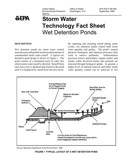
United StatesEnvironmental ProtectionAgencyOffice of <strong>Water</strong>Washington, D.C.<strong>Storm</strong> <strong>Water</strong><strong>Technology</strong> <strong>Fact</strong> <strong>Sheet</strong><strong>Wet</strong> <strong>Detention</strong> <strong>Ponds</strong>EPA 832-F-99-048September 1999DESCRIPTION<strong>Wet</strong> detention ponds are storm water controlstructures providing both retention and treatment ofcontaminated storm water runoff. A typical wetdetention pond design is shown in Figure 1. Thepond consists of a permanent pool of water intowhich storm water runoff is directed. Runoff fromeach rain event is detained and treated in the ponduntil it is displaced by runoff from the next storm.By capturing and retaining runoff during stormevents, wet detention ponds control both stormwater quantity and quality. The pond’s naturalphysical, biological, and chemical processes thenwork to remove pollutants. Sedimentationprocesses remove particulates, organic matter, andmetals, while dissolved metals and nutrients areremoved through biological uptake. In general, ahigher level of nutrient removal and better stormwater quantity control can be achieved in wetSource: Maryland Department of the Environment, 1986.FIGURE 1 TYPICAL LAYOUT OF A WET DETENTION POND
detention ponds than can be achieved with otherBest Management Practices (BMPs), such as dryponds, infiltration trenches, or sand filters.There are several common modifications that canbe made to the ponds to increase their pollutantremoval effectiveness. The first is to increase thesettling area for sediments through the addition ofa sediment forebay, as shown in Figure 1. Heaviersediments will drop out of suspension as runoffpasses through the sediment forebay, while lightersediments will settle out as the runoff is retained inthe permanent pool. A second commonmodification is the construction of shallow ledgesalong the edge of the permanent pool. Theseshallow peripheral ledges can be used to establishaquatic plants that can impede flow and trappollutants as they enter the pond. The plants alsoincrease biological uptake of nutrients. In additionto their function as aquatic plant habitat, the ledgesalso have several other functions, which can includeincluding acting as a safety precaution to preventaccidental drowning and providing easy access tothe permanent pool to aid in maintenance. Finally,perimeter wetland areas can also be created aroundthe pond to aid in pollutant removal.APPLICABILITY<strong>Wet</strong> detention ponds have been widely usedthroughout the U.S. for many years. Many of theseponds have been monitored to determine theirperformance. EPA Region V is currentlyperforming a study on the effectiveness of 50 to 60wet detention ponds. Other organizations, such asthe Washington, D.C., Council of Governments(WMCOG) and the Maryland Department of theEnvironment, have also conducted extensiveevaluations of wet detention pond performance.ADVANTAGES AND DISADVANTAGES<strong>Wet</strong> detention ponds provide both storm waterquantity and quality benefits, and providesignificant retrofit coverage for existingdevelopment. Benefits include decreased potentialfor downstream flooding and stream bank erosionand improved water quality due to the removal ofsuspended solids, metals, and dissolved nutrients.While the positive impacts from a wet detentionponds will generally exceed any negative impacts,wet detention ponds that are improperly designed,sited, or maintained, may have potential adverseaffects on water quality, groundwater, cold waterfisheries, or wetlands. Improperly designed ormaintained ponds may result in stratification andanoxic conditions that can promote the resuspensionof solids and the release of nutrients and metalsfrom the trapped sediments. In addition,precautions should be taken to prevent damage towetland areas during pond construction. Finally, thepotential for groundwater contamination should becarefully evaluated. However, studies to dateindicate that wet detention ponds do notsignificantly contribute to groundwatercontamination (Schueler, 1992).The following limitation should also be consideredwhen determining the feasibility of installing a wetdetention pond:1. <strong>Wet</strong> detention ponds must be able tomaintain a permanent pool of water.Therefore, ponds cannot be constructed inareas where there is insufficientprecipitation to maintain the pool or in soilsthat are highly permeable. In wetter regions,a small drainage area may be sufficient toensure that there is enough water tomaintain a permanent pool; whereas in morearid regions, a larger drainage area may berequired. In some cases, soils that are highlypermeable may be compacted or overlaidwith clay blankets to make the bottom lesspermeable.2. Land constraints, such as small sites orhighly developed areas, may preclude theinstallation of a pond.3. Discharges from ponds usually consist ofwarm water, and thus pond use may belimited in areas where warm waterdischarges from the pond will adverselyimpact a cold water fishery.4. The local climate (i.e., temperature) mayaffect the biological uptake in the pond.
5. Without proper maintenance, theperformance of the pond will drop offsharply. Regular cleaning of the forebays isparticularly important. Maintaining thepermanent pool is also important inpreventing the resuspension of trappedsediments. The accumulation of sedimentsin the pond will reduce the pond’s storagecapacity and cause a decline in itsperformance. Therefore, the bottomsediments in the permanent pool should beremoved about every 2 to 5 years. In mostcases, no specific limitations have beenplaced on disposal of sediments removedfrom wet detention ponds. Studies to dateindicate that pond sediments are likely tomeet toxicity limits and can be safelylandfilled (NVPDC, 1992). Some stateshave allowed sediment disposal on-site, aslong as the sediments are deposited awayfrom the shoreline to prevent their re-entryinto the pond.DESIGN CRITERIAIn general, pond designs are unique for each siteand application. Criteria for selecting the site forinstallation of the pond should include the site’sability to support the pond environment, as well asthe cost effectiveness of locating a pond at thatspecific site. In addition, the pond should belocated where the topography of the site allows formaximum storage at minimum construction costs(NVPDC, 1992). Site-specific constraints for pondconstruction may include wetlands impacts,existing utilities (e.g., electric or gas) that would becostly to relocate, and underlying bedrock thatwould require expensive blasting operations toexcavate.The site must have adequate base-flow from thegroundwater or from the drainage area to maintainthe permanent pool. Typically, underlying soilswith permeabilities of between 10 -5 and 10 -6 cm/secwill be adequate to maintain a permanent pool.All local, state and federal permit requirementsshould be established prior to initiating the ponddesign. Depending on the location of the pond,required permits and certifications may includewetland permits, water quality certifications, damsafety permits, sediment and erosion control plans,waterway permits, local grading permits, land useapprovals, etc.(Schueler, 1992). Since many statesand municipalities are still in the process ofdeveloping or modifying storm water permitrequirements, the applicable requirements should beconfirmed with the appropriate regulatoryauthorities.<strong>Wet</strong> detention ponds should be designed to meetboth storm water quality and quantity controlrequirements. <strong>Storm</strong> water quantity requirementsare typically met by designing the pond to controlpost-development peak discharge rates topre-development levels. Usually the pond isdesigned to control multiple design storms (e.g. 2-and/or 10-year storms) and safely pass the 100-yearstorm event. However, the design storm may varydepending on local conditions and requirements.<strong>Storm</strong> water quality control is achieved throughpollutant removal in the permanent pool. Removalefficiency is primarily dependent on the length oftime that runoff remains in the pond, which isknown as the pond’s Hydraulic Residence Time(HRT). As discussed above, wet detention pondsremove pollutants through both sedimentation andbiological uptake processes, both of which increasewith the length of time runoff remains in the pond.These processes can be modeled to determine adesign HRT using either the solids settling methodor the eutrophication method, respectively(Hartigan, 1988).The calculated HRT will be dependent on themethod selected. HRTs calculated by theeutrophication method can be up to three timesgreater than HRTs calculated by the solids settlingmethod. The longer HRTs associated with theeutrophication method appear to be due to theslower reaction rates associated with the biologicalremoval of dissolved nutrients (Hartigan, 1988).Once the design HRT has been determined, theactual dimensions of the pond must be calculated toachieve the design HRT. The primary factorcontributing to a pond’s HRT is its volume.Because many wet detention ponds are restricted inarea, pond depth can be an important factor in the
pond’s overall volume. However, the depth of thepool also affects many of the pond’s removalprocesses, and so it must be carefully controlled. Itis important to maintain a sufficient permanent pooldepth in order to prevent the resuspension oftrapped sediments (NVPDC, 1992). Conversely,thermal stratification and anoxic conditions in thebottom layer might develop if permanent pooldepths are too great. Stratification and anoxicconditions may decrease biological activity.Anoxic conditions may also increase the potentialfor the release of phosphorus and heavy metalsfrom the pond sediments (NVPDC, 1992). Thesefactors dictate that the permanent pool depth shouldnot exceed 6 meters (20 feet). The optimal depthranges between 1 and 3 meters (3 and 9 feet) formost regions, given a 2 week HRT (Hartigan,1988).Other key factors to be considered in the ponddesign are the volume and area ratios. The volumeratio, VB/VR, is the ratio of the permanent poolstorage (VB) to the mean storm runoff (VR).Larger VBs and smaller VRs provide for increasedretention and treatment between storm events. LowVB/VR ratios result in poor pollutant removalefficiencies.The area ratio, A/As, is the ratio of the contributingdrainage area (A) to the permanent pool surfacearea (As). The area ratio is also an indicator ofpollutant removal efficiency. Data from previousstudies indicates that area ratios of less than 100typically have better pollutant removal efficiencies(MD DEQ, 1986).The contours of the pond are also important. Thepond should be constructed with adequate slopesand lengths. While a length-to-width ratio isusually not used in the design of wet detentionponds for storm water quantity management, a 2:1length-to-width ratio is commonly used when waterquality is of concern. In general, highlength-to-width ratios (greater than 2:1) willdecrease the possibility of short-circuiting and willenhance sedimentation within the permanent pool.Baffles or islands can also be added within thepermanent pool to increase the flow path (Hartigan,1988). Shoreline slopes between 5:1 and 10:1 arecommon and allow easy access for maintenance,such as mowing and sediment removal (Hartigan,1988). In addition, wetland vegetation is difficult toestablish and maintain on slopes steeper than 10:1.<strong>Ponds</strong> should be wedge-shaped so that flow entersthe pond and gradually spreads out. This minimizesthe potential for zones with little or no flow(Urbonas, 1993).The design of the wet pond embankment is anotherkey factor to be considered. Proper design andconstruction of the embankments will prolong theintegrity of the pond structure. Subsidence andsettling will likely occur after an embankment isconstructed. Therefore during construction, theembankment should be overfilled by at least 5percent (SEWRPC, 1991). Seepage through theembankment can also affect the stability of thestructure. Seepage can generally be minimized byadding drains, anti-seepage collars, and coretrenches. The embankment side slopes can beprotected from erosion by using minimum sideslopes of 2:1 and by covering the embankment withvegetation or rip-rap. The embankment should alsohave a minimum top width of 2 meters (6 feet) toaid in maintenance.Finally, the internal flow control of the pond mustbe considered. Discharge from the pond iscontrolled by a riser and an inverted release pipe.Normal flows will be discharged through the wetpond outlet, which consists of a concrete orcorrugated metal riser and barrel. The riser is avertical pipe or inlet structure that is attached to thebase with a watertight connection. Risers aretypically placed in or adjacent to the embankmentrather than in the middle of the pond. This provideseasy access for maintenance and prevents the use ofthe riser as a recreation spot (e.g. diving platformfor kids) (Schueler, 1988). The barrel is ahorizontal pipe attached to the riser that conveysflow under the embankment.Typically, flow passes through an inverted pipeattached to the riser, as shown in Figure 1, whilehigher flows will pass through a trash rack installedon the riser. The inverted pipe should dischargewater from below the pond water surface to preventfloatables from clogging the pipe and to avoiddischarging the warmer surface water. Clogging ofthe pipe could result in overtopping of the
embankment and damage to the embankment(NVPDC, 1992). Flow is conveyed through thenear horizontal barrel and is discharged to thereceiving stream. Rip-rap, plunge pools, or otherenergy dissipators, should be placed at the outlet toprevent scouring and to minimize erosion. Rip-rapalso provides a secondary benefit of re-aeration ofthe pond discharges.Planners should consider both the design storm andpotential construction materials when designing andconstructing the riser and barrel. Generally, theriser and barrel are sized to meet the storm watermanagement design criteria (e.g. to pass a 2-year ora 10-year storm event). In many installations, theriser and barrel are designed to convey multipledesign storms (Urbonas, 1993). To increase the lifeof the outlet, the riser and barrel should beconstructed of reinforced concrete rather thancorrugated metal pipe (Schueler, 1992). The riser,barrel, and base should also provide have sufficientweight to prevent flotation (NVPDC, 1992).In most cases, emergency spillways should beincluded in the pond design. Emergency spillwaysshould be sized to safely pass flows that exceed thedesign storm flows. The spillway prevents pondwater levels from overtopping the embankment,which could cause structural damage to theembankment. The emergency spillway should belocated so that downstream buildings and structureswill not be negatively impacted by spillwaydischarges. The pond design should include a lowflow drain, as shown in Figure 1. The drain pipeshould be designed for gravity discharge and shouldbe equipped with an adjustable gate valve.PERFORMANCEThe primary pollutant removal mechanism in a wetdetention pond is sedimentation. Significant loadsof suspended pollutants, such as metals, nutrients,sediments, and organics, can be removed bysedimentation. Other pollutant removalmechanisms include algal uptake, wetland plantuptake, and bacterial decomposition (Schueler,1992). Dissolved pollutant removal also occurs asa result of biological and chemical processes(NVPDC, 1992).The removal rates of conventional wet detentionponds (i.e., without the sediment forebay orperipheral ledges) are well documented and areshown in Table 1. The wide range in the removalrates is a result of varying hydraulic residence times(HRTs), which is further discussed in the DesignCriteria section. Increased pollutant removal bybiological uptake and sedimentation is correlatedwith increased HRTs. Proper design andmaintenance also effect pond performance.Studies have shown that more than 90 percent of thepollutant removal occurs during the quiescentperiod (the period between the rainfall events) (MDDEQ, 1986). However, some removal occursduring the dynamic period (when the runoff entersthe pond). Modeling results have indicated thattwo-thirds of the sediment, nutrients and trace metalloads are removed by sedimentation within 24TABLE 1 REMOVAL EFFICIENCIESFROM WET DETENTION PONDSParameterTotalSuspendedSolidTotalPhosphorusSolubleNutrientsPercent RemovalSchueler,1992Hartigan,198850-90 80-9030-90Lead 70-80Zinc 40-50BiochemicalOxygenDemand orChemicalOxygenDemand40-80 50-7020-401 hydraulic residence time varies2 hydraulic residence time of 2 weeksSource: Schueler, 1992 & MD DEQ, 1986.
hours. These projections are supported by theresults of the EPA's 1993 National Urban RunoffProgram (NURP) studies. However, other studiesindicate that an HRT of two weeks is required toachieve significant phosphorus removal (MD DEQ,1986).The pond’s treatment efficiency can be enhanced byextending the detention time in the permanent poolto up to 40 hours. This allows for a more gradualrelease of collected runoff, resulting in bothincreased pollutant removal and control of peakflows (Hartigan, 1988).OPERATION AND MAINTENANCE<strong>Wet</strong> detention ponds function more effectivelywhen they are regularly inspected and maintained.Routine maintenance of the pond includes mowingof the embankment and buffer areas and inspectionfor erosion and nuisance problems (e.g. burrowinganimals, weeds, odors) (SEWRPC, 1991). Trashand debris should be removed routinely to maintainan attractive appearance and to prevent the outletfrom becoming clogged. In general, wet detentionponds should be inspected after every storm event.The embankment and emergency spillway shouldalso be routinely inspected for structural integrity,especially after major storm events. Embankmentfailure could result in severe downstream flooding.When any problems are observed during routineinspections, necessary repairs should be madeimmediately. Failure to correct minor problemsmay lead to larger and more expensive repairs oreven to pond failure. Typically, maintenanceincludes repairs to the embankment, emergencyspillway, inlet, and outlet; removal of sediment; andcontrol of algal growth, insects, and odors(SEWRPC, 1991). Large vegetation or trees thatmay weaken the embankment should be removed.Periodic maintenance may also include thestabilization of the outfall area (e.g. adding rip-rap)to prevent erosive damage to the embankment andthe stream bank. In most cases, sediments removedfrom wet detention ponds are suitable for landfilldisposal. However, where available, on-site use ofremoved sediments for soil amendment will reducemaintenance costs.COSTSTypical costs for wet detention ponds range from$17.50-$35.00 per cubic meter ($0.50-$1.00 percubic foot) of storage area (CWP, 1998). The totalcost for a pond includes permitting, design andconstruction, and maintenance costs. Permittingcosts may vary depending on state and localregulations. Typically, wet detention ponds are lesscostly to construct in undeveloped areas than toretrofit into developed areas. This is due to the costof land and the difficulty in finding suitable sites indeveloped areas. The cost of relocating pre-existingutilities or structures is also a major concern indeveloped areas. Several studies have shown theconstruction cost of retrofitting a wet detentionpond into a developed area may be 5 to 10 times thecost of constructing the same size pond in anundeveloped area. Annual maintenance costs cangenerally be estimated at 3 to 5 percent of theconstruction costs (Schueler, 1992). Maintenancecosts include the costs for regular inspections of thepond embankments, grass mowing, nuisancecontrol, debris and liter removal, inlet and outletmaintenance and inspection, and sediment removaland disposal. Sediment removal cost can bedecreased by as much as 50 percent if an on-sitedisposal areas are available (SEWRPC, 1991).REFERENCES1. Center for <strong>Water</strong>shed Protection, 1998.Cost and Benefits of <strong>Storm</strong> <strong>Water</strong> BMPs.2. Hartigan, J.P., 1988 “Basis for Design of<strong>Wet</strong> <strong>Detention</strong> Basin BMPs,” in Design ofUrban Runoff Quality Control. AmericanSociety of Engineers. 1988.3. Maryland Department of the Environment,1986. Feasibility and Design of <strong>Wet</strong> <strong>Ponds</strong>to Achieve <strong>Water</strong> Quality Control.Sediment and <strong>Storm</strong> <strong>Water</strong> Administration.4. Northern Virginia Planning DistrictCommission, Engineers and SurveyorsInstitute, 1992. Northern Virginia BMPHandbook.
5. Schueler, T.R., 1992. A Current Assessmentof Urban Best Management Practices.Metropolitan Washington Council ofGovernments.6. Southeastern Wisconsin Regional PlanningCommission, 1991. Costs for UrbanNonpoint Source <strong>Water</strong> Pollution ControlMeasures. Technical Report No. 31.Southwest Florida <strong>Water</strong> Management DistrictBetty Rushton2379 Broad StreetBrooksville, FL 34609The mention of trade names or commercial productsdoes not constitute endorsement or recommendationfor the use by the U.S. Environmental ProtectionAgency.7. Urbonas, Ben and Peter Stahre, 1993.<strong>Storm</strong> <strong>Water</strong> Best Management Practicesand <strong>Detention</strong> for <strong>Water</strong> Quality, Drainageand CSO Management. PTR Prentice Hall,Englewood Cliffs, New Jersey.ADDITIONAL INFORMATIONCity of Charlotte, North CarolinaSteve Sands<strong>Storm</strong> <strong>Water</strong> Services, Engineering and PropertyManagement600 East 4 th StreetCharlotte, NC 28202Illinois EPACharles FellmanAuxiliary Point Source Program, Permit Section,Division of <strong>Water</strong> Pollution Control1021 N. Grand Avenue East, P.O. Box 19276Springfield, IL 62794Minnehaha Creek <strong>Water</strong>shed DistrictPete CangialosiGray Freshwater Center, Navarre2500 Shadywood Road, Suite 37Excelsior, MN 55331Polk County, FloridaBob KollingerNatural Resources and Drainage Division4177 Ben Durrance RoadBartow, FL 33830City of Reynoldsburg, OhioLarry Ward<strong>Storm</strong> <strong>Water</strong> Utility7806 East Main StreetReynoldsburg, OH 43068For more information contact:Municipal <strong>Technology</strong> BranchU.S. EPAMail Code 4204401 M St., S.W.Washington, D.C., 20460