Table of Contents - Supco
Table of Contents - Supco
Table of Contents - Supco

Create successful ePaper yourself
Turn your PDF publications into a flip-book with our unique Google optimized e-Paper software.
SUPCO Part No. Page SUPCO Part No. Page SUPCO Part No. PageSUPCO Part Number IndexiiiiSUPCO PART NO.Page31 6670 6675 665011 145014 149063 49064 49065 49066 49067 49068 49069 49070 49071 410475 68, 6911093 7513495 7514263 7514265 7514753 8714754 8719994 7519995 7520540 755-Apr 443004 53, 5443005 53, 5443054 50, 5443055 50, 5443057 51, 5443058 51, 5443154 51, 5443168 51, 5443309 53, 5443320 53, 5443355 52, 5443359 53, 5443503 52, 5443558 52, 5443658 51, 5443658 52, 5443665 52, 5443758 52, 5443855 50, 5490290 590291 590292 590293 590294 590295 590340 490341 490342 490370 590372 590374 590380 590382 5SUPCO PART NO. Page SUPCO PART NO. Page90384 514265-001 8724H10BAR 9324H150PSI 9324H3.5BAR 9324H35BAR 9324H500PSI 9324H50PSI 9330-220-0S 6630-OS 6630WM 6631-220 6631D10BAR 9331D150PSI 9331D3.5BAR 9331D35BAR 9331D500PSI 9331D50PSI 9331WM 6650100B 1450103B 1450150B 1450153B 145PAK 296H10BAR 936H150PSI 936H3.5BAR 936H35BAR 936H500PSI 936H50PSI 9370056A 10670056B 10670-220 6670CSA 6670CSA220 6675-220 667D10BAR 937D150PSI 937D3.5BAR 937D35BAR 937D500PSI 937D50PSI 939900H 1179904H 1179904K 1179906H 1179906K 1179915K 117A100 32A105 32A110 32A112 32A116 32A120 32A124 32A128 32A136 32A144 32A158 32A19 thru A99 32ADTA 75, 83ADTA 89ADTA 91APP120 11AT012 thru AT015 39AT021 39AT022 39B101 thru B360 32B23 thru B99 32BC1 thru BC5 29BC1-100 thru BC5-100 29BJ10 105BJ10PLUS 105BPV12 61BPV14 61BPV21 61BPV31 61BPV31D 61BPV34 61BPV36 61BPV38 61BPV56 61BPV58 61BPV78 61BTG-54VL 55BTG-54VLW 55BTG-DB2 55BTG-DK 55BTG-DO 55BTG-EK 55BTG-EM 55BTG-EO 55BTG-K 55BTG-KM 55BTG-KWM 55BTG-O 55BTG-RB2 55BTG-RK 55BTG-RM 55BTG-RO 55BTG-RWM 55BTG-UK2 55BTG-UM 55BTG-UO2 55BTG-UV2 55BTG-UWM 55BX35 thru BX300 32CABLE10H 83CABLE10H 87CABLE10H 89CABLE10H 91CABLE10H 96CABLE10T 87CABLE10T 91CABLE15 91CABLE15 94
SUPCO Part No. Page SUPCO Part No. Page SUPCO Part No. PageSUPCO Part Number IndexivivSUPCO PART NO. Page SUPCO PART NO. Page SUPCO PART NO. PageDP40242 8, 9DP40243 8, 9DP501203 8, 9DP502403 8, 9DP50243 8, 9DP601203 8, 9DP602403 8, 9DP60243 8, 9DP751203 8, 9DP752403 8, 9DP75243 8, 9DP901203 8, 9DP902403 8, 9DP90243 8, 9DPG100 69DPG1000 69DPG25V 69DPGT 94DPGT220EU 94DPGT220UK 94DPGT220US 94DR10 97DR40 97DSP1000 71DTK-1-4LVLP-D 11DTK-1-4LVLP-LV 11DTK-1LVLP-D 11DTK-1LVLP-LV 11DTK-240-3CMPLUS 11DTK-2LVLP-SCP-RUV 11DTK-4LVLP 11DVTH 82E20120F12 89E20120F12 98E20120F24 89E20120F24 98E20120F31 89E20120F31 98E20120F7 89E20120F7 98E2050F12 89E2050F24 89E2050F31 89E2050F31 98E2050F7 89E2050F7 98E3010524 89E3010C12 89E3010C12 98E3010C24 98E3010C31 89E3010C31 98E3010C7 89E3010C7 98E3050524 89E3050C12 89E3050C12 98E3050C24 98E3050C31 89E3050C31 98E3050C7 89E3050C7 98E40110F12 89E40110F12 98E40110F24 89E40110F24 98E40110F31 89E40110F31 98E40110F7 89E40110F7 98E545C12 89E545C12 98E545C24 89E545C24 98E545C31 89E545C31 98E545C7 89E545C7 98ECAP321 56EDT10 14EDT11 14EDT12 14EDT12-20 14EDT13 14EDT13-20 14EDT20 14EDT21 14ELB101 101ELB201 101ELB250 101ELB251 101ELB301 101ELB304 101ELB305 101ELB312 101ELB320 101ELB321 101ELB340 101ELB400 102ELB400 103ELB402 102ELB701 103ELB710 103ELB711 103ELB713 102ELB714 101ELB717 100ELB721 103ELB910 100ELB913 100EVENT-6H 93EVENT-7D 93F3050C12 98F336 55FB101 thru FB109 21FB152 thru FB191 21FB250 20FB302 20FB325 20FB350 20FB353 21FB401 20FB402 19FB402 20FB403 20FB404 20FB450 21FB455 19FB455 21FB460 20FB461 20FB501 20FB504 20FB550 19FB550 20FB551 20FB590 20FB601 20FB604 20FB650 20FB651 20FB660 20FB665 20FB701 20FB702 20FB703 20FB718G 21FB803 20FBP100 103FC1113 104FC1214 104FC1617 104FC1820 104FC2224 104FC4011 34FC4031 34FCO810 104FCO915 104FL135 thru FL350-50 41FL50 39FL60 39FLD135 41FLD205 41FPT10 104FPT13 104FPT15 104FTV12 62FWB1 105G403K 43, 44GC401 15GC405 15GC410 15GC501 15GC503 15
vSUPCO Part No. Page SUPCO Part No. Page SUPCO Part No. PageSUPCO Part Number IndexSUPCO PART NO. Page SUPCO PART NO. Page SUPCO PART NO. PageGC505 15GC506 15GC601 15GC602 15GC604 15GC607 15GC701 15GC702 15GC707 15GFK1 19HK7 105HL758 38HP083 thru HP165S 27HS10001 112HS10004 112HS10016 112HS10128 112HS11001 112HS11004 112HS11016 112HS11128 112HS12001 112HS15128 115HS15128 117HS16001 114HS16501 114HS17001 112HS17004 112HS17016 112HS18004 114HS20004 113HS20016 113HS20128 113HS21004 113HS21016 113HS21128 113HS22008 113HS22032 113HS22128 113HS23008 113HS23032 113HS23128 113HS24000 114HS24010 114HS24128 114HS26004 113HS26016 113HS26128 113HS30004 112HS30016 112HS50004 116HS51032 114HS52032 116HS52105 116HS52115 116HS52128 116HS55032 115HS56011 115HS57014 115HS58128 115HS58520 116HS59128 115HS59520 116HSINJ001 113HSUVB001 112HT100 2, 125, 126, 127HT70 2, 125, 126, 127HT80 2, 125, 126, 127HT90 2, 125, 126, 127HTP5 91HTP5 92HTP5100 91HTP5100 92HTP515 91HTP515 92HTP525 91HTP525 92HTP550 91HTP550 92HVT2 104IAQ50 79IAQ55 79IC100 60IC102 60ICG1 58ICG-220 58IG4000 43IG401 43, 44IG402K 43, 44IG405 43, 44IG406 43, 44IG412 43, 44IG414 43, 44IM1 105IM2 105IM3 105IM4 105IM5 105IMK3 105KA12 117KEL 93KES 93KEV 93KPP 96KPT 97KTE 96KTE 97KTH 89KTH 91KTH 96KTH 97KTP 96KTP 97KTT 96KTT 97L120 thru L340 42L135DC 39L145DC 39L210DC 39L420 84, 86LCV 84, 86LD120 thru LD305 42LIT11TC 70LIT6 70LIT8B 70LITH9B 87LLD032 thru LLD309S 25LLS 87LLS 87LLSU 87LLSU 87LPT 84, 86LT2 84, 85LTC 84, 85LTH 84, 85LTT 84, 85M044 111M098 111M444 111M500 77M501 77M814520 13MCASE 77MCASE 96MD5 24MD6 24MD7 24MFD10 77MFDCASE 68, 69MFDCASE 77MFDFUSE 77MTM1028 80OL1 60OL2 60OL3 60OL4 60OPR021 59OV32 60OV34 60, 61OV36 60, 61OV38 60, 61OV40 60, 61OV42 60, 61OV44 60, 61OV46 60, 61OV48 60, 61OV50 60P89 104PC6 96PIT1 70PO115 58PO230 58POP3 56POP5 56v
SUPCO Part No. Page SUPCO Part No. Page SUPCO Part No. PageSUPCO Part Number IndexviviSUPCO PART NO. Page SUPCO PART NO. Page SUPCO PART NO. PagePRO21 58PRO22 58PRO41 58PRO42 58PRO62 58PRO81 58PRO82 58PT100 71, 72PT100C 71PT100H 71PT100HC 71Q101 thru Q116 36RC1220 102RC2106 102RC2108 102RC2110 102RC2112 102RC3110 102RC3114 102RC5003 100RC5010 100RC5019 100RCB1 105RCO210 58RCO220 58RCO410 58RCO420 58RCO620 58RCO810 58RCO820 58RO41 58RO42 58RO62 58RO81 58RO82 58RPT61 78RSC20 58RW516 105RW916 105RWA10 105S0100 111S0100F24 94S0100F7 94S045C24 94S045C7 94S20120F24 94S20120F7 94S210 thru S220 24S3050C24 94S3050C7 94S4590F24 94S4590F7 94S8 111S804100 13S804120 13S804500 13S804520 13S814100 13S814120 13S814500 13S814520 13SA1 62SA2 62SAB233 99SAB243 99SAB444 99SAB454 99SAB515 99SAB710 99SAR21 106SB001 20SC1002 15SCASE 78SCCP 81SCDM 81SCM 10, 128SCM1 10SCMPLUG 11SCMPLUS 10, 128SCR11 91SCR12 91SD100F7 94SD120F24 94SD120F7 94SD50C7 94SF0099 61SF0101 61SF0111 61SF1010 62SF1060 61SF1090 61SF1414 63SF1818 63SF2010 64SF2012 64SF2020 64SF2028 64SF2035 64SF2060 64SF2070 64SF2090 64SF2235 63SF2245 63SF2250 63SF2525 62SF2595 64SF2597 64SF3500 103SF3510 103SF3515 103SF3525 103SF3535 103SF3570 103SF3600 62SF3602 62SF3603 62SF3604 62SF3605 62SF3606 62SF3608 62SF3800 65SF3813 65SF3900 65SF3910 65SF3920 65SF3930 65SF3970 65SF4040 63SF4311 65SF4311 104SF4314 65SF4450 63SF5014 64SF5050 64SF5161 63SF5421 62SF5501 61SF5501 63SF5512 63SF5514 63SF5516 63SF5518 63SF5534 63SF5538 63SF5555 65SF5558 63SF5578 63SF8400 63SF8403 63SF8404 63SF8404 63SF8405 63SF8406 63SF8412 63SF8414 63SF8416 63SF8418 63SF8434 63SF8458 63SF8478 63SF8725 64SF9601 64SF9602 64SF9603 64SF9613 65SF9614 65SF9615 65SF9616 65SF9620 65SF9644 65SFC75120 thru SFC300400 23SFPC 41SG3970 104SG4314 104
viiSUPCO Part No. Page SUPCO Part No. Page SUPCO Part No. PageSUPCO Part Number IndexSUPCO PART NO. Page SUPCO PART NO. Page SUPCO PART NO. PageSGV05 thru SGVA2 107SH201 thru SH207 67SH221 thru SH226 67SH250 67SH251 thru SH252 67SH281 thru SH284 67SH500 thru SH505 67SHF110 thru SHF250 39SHF90 39SHL120 thru SHL325 39SHL501 thru SHL519 37SHM125 thru SHM350 37SHP200150 thru SHP610420 22SHS03 thru SHSA2 107SHS50 67SIG100 thru SIG111 47, 48. 49SIG1100 47, 48, 49SIG401 thru SIG414 47, 48, 49SIS018 56SK3W2 3SK3W3 3SK3W4S 3SK3W5 3SK3W6S 3SL300T 88SL300TH 88SL5703 40SL5708 40SL79002 40SL79005 40SLF130VA 38SLF155VA 38SLF158VB 38SLF165VA 38SLF170VA 38SLF185VB 38SLF190HA 38SLF194HB 38SLF194VB 38SLF200HA 38SLF200VA 38SLF210HA 38SLF222VA 38SLF230HA 38SLF230HB 38SLF250HA 38SLF252VB 38SLF255VA 38SLF260HA 38SLF275HB 38SLF275VB 38SLF280HB 38SLF300HB 38SLF300VA 38SLF330VA 38SLP0520 thru SLP90120 22SLS120 38SLS130 38SLS140 38SLS145 38SLS150 38SLS155 38SLS160 38SLS165 38SLS170 38SLS175 38SLS180 38SLS200 38SLS250 38SLS255 38SLS265 38SLS275 38SLS285 38SLS295 38SLS300 38SLS300HB 38SLS350 38SM140-40A 18SM550 thru SM556 17SM670 thru SM681 18SM6700B 19SM683 18SM684 18SM685 18SM690C 18SM691 18SM692 18SM700 thru SM705 17SM775 18SM998 17SM999 17SMR375 thru SMR610 22, 23SP12C 56SP18 56SP18C 56SP2 56SP2C 56SP3 56SP3C 56SP4 56SP4C 56SP6 56SP6C 56SPP 3SPP10E 3SPP4E 3SPP5 3SPP5E 3SPP5TD 5SPP6 3SPP6E 3SPP6TD 5SPP7E 3SPP7S 3SPP8E 3SPP9E 3SR4-20 90, 91SR6N1 106SRB 90, 91SRC 90, 91SRJ 90, 91SRL130 38SRL135 38SRL220 38SRL230 38SRL240 38SRL250 38SRL260 38SRL300 38SRL300ICP 38SRL350 38SRTH 90, 91SRV 90, 91SRVLA 91SS410 58SSGFM2 thru SSGFM4 28SSGSS2 thru SSGSS5 28SSGSS7 28SSLD83 thru SSLD419S 26, 27SSN2000 45, 46SSN24 47, 48, 49SSN3000 45, 46SSN3016 45, 46SSN4000 45, 46ST01 thru ST04 73ST06 thru ST08 73ST09 73ST10 73ST200 111STC4162 thru STC6377 40STC4257 33STC4283 33STC4300 33STC4333 33STC4358 33STC4438 33STC4468 33STC5257 33STC5300 33STC5333 33STC5337 33STC5377 33STC6257 33STC6300 33STC6333 33STD5-105 72STF4170 thru STF4305B 40STV2 62STV2D 62STV3 62STV4 62SUD103 23SUD109 thru SUD116 23SUPR 4vii
SUPCO Part No. Page SUPCO Part No. Page SUPCO Part No. PageSUPCO Part Number IndexviiiviiiSUPCO PART NO. Page SUPCO PART NO. Page SUPCO PART NO. PageSW100 75SW100 87SW25 75SW25 87SW50 75SW50 87SW75 75SW75 87SWC03 thru SWCA1 107SXT 79R 35SXT100R 35SXT101 35SXT103 thru SXT106 35SXT111 thru SXT116 35SXT148 35SXT150 35SXT160 35T1001 thru T1197 107, 108, 109, 110T1121 thru T1125 42T2001 thru T2112C 107, 108, 109, 110T45 34TA2 74TA22 74TA2-220 74TA2-220C 74TA2C 74TA3001 106TA3-220 76TA3C 76TA3C220 76TA3P 75TA3P 76TA6 74TA6220 74TA6C 74TA6C220 74TA7 74TA7C 74TA7PROBE 75TAL2 76TAP4 76TAP4-220 76TAP4-220 76TAP4C 76TC103 106TC104 106TC2 104TCW100 75TCW100 91TCW100 94TCW25 75TCW25 91TCW25 94TCW50 75TCW50 91TCW50 94TCW75 75TCW75 91TCW75 94TD68 16TD69 16TD69W 16TD72 16TD73 16TD73W 16TDP269 5TH7001 39TH7010 39THA2 75THA2P 75THC120 73THP2 73THP5 94THS60 106TLA 81TP15 91TP15 96TP6 96TPFDA 78TPFDA 81TPFDA 87TPM110 73TPMP2 12TPMPU 12TPP 78TPS 78TTP5 94UFC1 104UPR041 59UPRO81 59UR041 59URCO210 59URCO210RC 59URCO410 59URCO410RC 59URCO810 59URCO810RC 59URO81 59URSC10 59USBS 75USBS 87UW1 105V20120F31 98V20120F7D 98V2050F12 98V2050F31 98V2050F7 98V3010C12 98V3010C24 98V3010C31 98V3010C7 98V3050C24 98V3050C31 98V3050C7 98V40110F12 98V40110F24 98V40110F31 98V40110F7 98V545C12 98V545C24 98V545C34 98V545C7 98VG60 68, 69VG61 68, 69VG64 68, 69VG64S 68, 69VG65 68, 69VG66 68, 69VGC 68, 69VLCEL 83VLPAPER 83VLS CABLE 83VLSK 83VLT 83VLT PROBE 83VLT4-115 83VLT4-12 83VLT4-230 83VLTH PROBE 83VLTH-115 83VLTH-12 83VLTH-230 83VLWPCASE 83VPR 83VSG 68, 69WA100 80WH3 14WH4 14
Keep ScrollingDown1
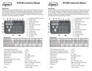
AC Hard StartsA/C Hard StartsChoosing the correct hard start for the application combines a technical need with a pr<strong>of</strong>essional preference.Select from the broadest <strong>of</strong>fering <strong>of</strong> Hard Starts from the Pioneer <strong>of</strong> Hard Start technology.Four (4) styles to choose from:• HT Series High Torque Series Relay (EPR)/Capacitor combination• SPPE Elite Series Electronic Potential Relay (EPR)/Capacitor combination• SPP Series PTC/Capacitor combination• SK3W Series 3-wire Potential Relay/Capacitor combinationApplications• Use on any single phase air conditioner or refrigeration unit• Low voltage situations• Hard starting compressorsNATE Recognized Course 1867-0002SUPCO Hard Start KitsHT Series - HIGH TORQUE Hard Start KitsMatching a high current potential relay with a high voltage capacitor means the ultimate Torque for the most reliable Hard Start Kits.Choose from 4 sizes for the best solution.Features/Benefits• Device includes high current potential relay and 330VAC start capacitor.• 40 Amp Electronic Potential relay (EPR) providessuperior performance for low voltage applications.• Senses Motor Start• Instant Re-start• Safety time delay if compressor fails to start• Easy 2-wire installation• Made in the USA• UL recognizedApplications• For use on ALL types <strong>of</strong> single phase208 – 277 VAC air conditioning, heat pumpand refrigeration compressors; includingreciprocating, scroll and rotary from 1 – 5 hp.®Product InformationSUPCO. RECOMMENDED INCREASE IN CAPACITOR CAPACITOR REPLACESPART NO. RANGE APPLICATION TORQUE (%) DIMENSIONS SPECIFICATIONS KICKSTARTHT70 1-3 hp Cap Tube & Orifice Metering Devices 1000 % 6 3/4”L X 1 9/16”W X 2 1/2”H 108-130 µF X 330 VAC KS8HT80 1-3 hp All Metering Devices 1000 % 6 3/4”L X 1 9/16”W X 2 1/2”H 189-227 µF X 330 VAC TO-5HT90 Maneurop All Maneurop 1000 % 6 3/4”L X 1 9/16”W X 2 1/2”H 233-280 µF X 330 VAC MP1Compressors Compressors +HT100 3.5 - 5 hp All Metering Devices 1000 % 6 3/4”L X 1 9/16”W X 2 1/2”H 270-324 µF X 330 VAC KS1+ Use HT80 for M/N’s MT18JA* MTEJA* & MTZ18JA** For HT Cross Reference refer to page 125 -12722Hard Start Comparison HT SPPE SK3W SPPSelection <strong>Table</strong> Series Series Series SeriesStart Sensing Technology Voltage Voltage Voltage NAUses Electronic Potential Relay (EPR) Yes Yes Yes NoInstant Re-Start Yes Yes Yes NoSenses Motor Start Yes Yes Yes NoTwo wire, non-polarized Yes Yes No YesOEM Style, 3-wire No No Yes NoReplaces 3-wire capacitor kit Yes Yes Yes YesUL approved Yes Yes Pending YesPTCR Device No No No YesBackup Timing Safety Circuit Yes Yes No NoPotentially damaging to motor windings No No No NoRequires non-replaceable fuse protection No No No No330V Capacitor Yes Yes Yes NoPotential Relay DevicesThe Potential Relay start device has recently been the subject <strong>of</strong> considerableattention in the market place. Several manufacturers are promoting productswith a variety <strong>of</strong> technologies. The primary distinction between the potentialrelay devices relates to a voltage sensing or current sensing capability.The voltage sensing method monitors start winding developed voltage andactuates a mechanical or electronic potential relay to disengage the startcapacitor. The electronic potential relay is inherently more reliable and precisethan the older type mechanical potential relay. SUPCO employs voltage sensingtechnology with an electronic potential relay.
AC Hard StartsSee Page 123-124for E Class AdvantageTech NotesSPPE ‘E Class’ Series EPR/Capacitor CombinationFeatures/Benefits• Electronic Potential RelayTechnology (EPR)• Backup electronic timing circuitto protect the compressor• Voltage sensing• Instant Re-start• Easy 2-wire installation• Can be used on PSC and CSIRtype compressors• 330 V Capacitor®OPERATINGPART VOLTAGE RECOMMENDED CAPACITORNO. (VAC) RANGE (hp) SIZE (µF)SPP4E 90 – 130 1/8 – 1 88 – 106SPP5E 170 – 277 1/3 – 2 43 – 52SPP6E 170 – 277 1/2 – 3 88 – 106SPP7E 170 – 277 1 – 4 130 – 156SPP8E 170 – 277 1 and up 189 – 227SPP9E 170 – 277 1 and up 233 – 280SPP10E 170 – 277 3 and up 270 – 324SPP Series PTC/Capacitor CombinationFeatures/Benefits• Positive Temperature CoefficientTechnology (PTC)• Field proven reliability• Easy 2-Wire installation• Most economicOPERATING®PART VOLTAGE RECOMMENDED INCREASENO. (VAC) RANGE (hp) IN TORQUE (%)SPP* 90 – 277 1/2 to 10 250%SPP5 90 – 277 1/2 to 10 300%SPP6 90 – 277 1/2 to 10 500%SPP7S 90 – 277 1/2 to 10 600%* This model does not include a capacitorSK3W Series 3-Wire Potential Relay/Capacitor CombinationFeatures/Benefits• OEM-Style 3-wire Installation• Instant re-start• Easy installation with “fast clamp-on” connection• Models for standard and scroll compressors• 330 VAC Start Capacitor VoltageDROP-OUT PICK-UP MAXIMUMPART hp VOLTAGE VOLTAGE COIL CAPACITORNO. RATINGS COMPRESSOR (VAC) (VAC) VOLTAGE SIZE (µF)SK3W2 1 thru. 2 hp Standard 60-135 204-233 500 VAC 88 - 108SK3W3 2 1/2 thru. 3 1/2 hp Standard 60-121 171-184 420 VAC 189 - 227SK3W5 4 thru. 5 hp Standard 60-121 171-184 420 VAC 243 - 292SK3W4S 3 thru. 4 hp Scroll 60-135 204-233 500 VAC 189 - 227SK3W6S 4 1/2 thru. 6 hp Scroll 60-121 171-184 420 VAC 270 - 324Application Note: 2-wire vs. 3-wire InstallationSK3W Series 3-wireHT, SPP & SPPESeries 2-wire“Fast Clamp-On” Connection(used with SK3W Series)SPPTO COMPRESSOR33
RelaysUniversal Potential RelaysReplacing all potential relays, these WIRE TO WIRE Universal Potential Relays <strong>of</strong>fer the ultimate in convenience. One potential relay to fit any application.Choose to “drop in” the SUPR Universal Potential Relay or “dial in” the exact pick-up voltage for the APR5 Adjustable Potential Relay. State <strong>of</strong> theArt electronic circuitry provides Wire to Wire replacement <strong>of</strong> any potential relay with added motor protection.Applications• Replaces all OEM potential relays• Use on any single phase motor orair conditioning and refrigerationcompressor up to 5 hp.Features/Benefits• Reduces inventory• Accomodates screw-on or push-on connections.• Wire to Wire Replacement for virtually ALL • Dimensions identical to industry standard potential relays.potential relays.• Easy replacement mounting with universal mounting bracket.• Recycles instantly• Start winding protection if motor does not start.• Replaces both 3 and 5 terminal potential relays • Prevents start capacitor venting when motor doesn’t start.• Normally closed contacts• Contact Material: Silver Cadmium OxideSUPR Universal Potential Relay• Time Function Relay• Start Time: 1.0 - 1.5 secondsAPR5 Adjustable Potential Relay• Adjustable, Voltage Sensitive Relay• Set pick-up voltage• Safety time out 1.0 – 1.5 secondsNote: See Technical Area for Application Note on RelaysCommon SpecificationsOperating Voltage 110 – 270 VAC, Single PhaseAmperage30 AMPMotor Power Rating up to 5 hpOperating Position Non-positional mounting.Universal Mounting Allows for easy installation. Unused portionsBracket<strong>of</strong> the bracket simply snap <strong>of</strong>f with pliers.TerminalsScrew or push-on. Adapters to convertscrew-on to push-on are provided.Dimensions 1.75W x 2.25L x 1.50H4490X Series Potential Relays• Meets all requirements <strong>of</strong>OEM relays• Universal break-<strong>of</strong>fbracketFeatures/Benefits• 50/60 cycle• Contact rating 35 amp@ 277 VAC• Non-positional• Instructions and wiringdiagram included in eachrelay®903X Series GeneralPurpose Switching RelaysDouble pole – double throw (DPDT)Applications• HVAC/ R• Appliance vending machines• Fan controls• Business machines®CONTINUOUSDROPPART Coil PICK-Up Out Replaces GE 3ARR3No. Voltage Min. Max. Max. Relay Groups*9063 170 139 153 55 2J; 2K; 2L; 2M; 5N; 7J; 7K; 7L; 7M; 7N; 8L;*Determine group from GE part number.8M; 8N9064 395 260 275 120 3A; 3B; 3AV; 3AU; 4A; 4B; 6A; 6B; 6AV; 10A;10B; 10AU; 10AV; 14A; 14B; 16A9065 332 168 182 90 3P; 3R; 3AP; 5P; 5R; 5S; 5T; 13P; 19N; 22S9066 395 215 225 120 3U; 3V; 3AT; 6U; 6V; 6W; 16U9067 420 295 315 125 3C; 3D; 3AA; 4C; 4D; 4BK; 6C; 6D; 6AA; 10C;10D; 26A; 26B; 26C; 26D9068 502 325 345 135 3E; 3F; 3AB; 3AC; 4E; 4F; 4G; 6E; 6F; 6G; 10H;10AB; 10AC; 26E; 26F; 26G; 26H; 27E; 27F; 27G9069 336 180 195 105 3S; 3T; 10S; 10T; 10AS; 13S; 13T; 20S; 25S; 25T9070 253 285 305 77 5B; 5C; 5D; 5AA; 8B; 8C; 8D; 27A; 27B; 27C9071 420 212 232 121 6TV; 6TW; 10V; 16TV; 20VPART Coil Terminal Terminal Cross ReferenceNo. Voltage 1-2-3 4-5-6 Essex/RBM Honeywell90340 24 power power 90-340 R8222D101490341 110/12 power power 90-341 R4222D101390342 208/240 power power 90-342 R4222N1021POWERCONTACT 208/240V 208/240VPilotRATINGS 120V 277V 120V 277VFull Load Amps 12 6 - -Resistive Amps* 15 15 3 3Locked Rotor Amps 60 35 - -Horsepower 3/4 3/4 1/10 1/10*0.75 power factor
HVAC - RelaysRelays902XX & 903XX Series General Purpose Fan RelaysEngineering Data• CONTACTS: SPST-NO, SPST-NC, SPDT, 1 NO/1 NC, Material/Power - Silver Alloy, Material 1/2 Pilot - Fine Silver• POWER RATINGS (All Forms): 125 VAC, 18A Resistive, 12 FLA, 60LRA, 240/277 VAC, 18A Resistive, 8 FLA, 48 LRA• SPECIAL POWER RATINGS (Form 1 & 2): 125 VAC, 14 FLA, 84LRA, 277 VAC, 25A Resistive• PILOT RATINGS (All Forms): 3A, 277 VAC Gen. Purpose, 250 VA@ 250 VAC, 277 VA @ 277 VAC, 125 VA @ 125 VAC• COILS : Voltage Ratings - 24, 120, 208/240, 77 VAC, 12, 24 VACFrequency - 50/60 Hz Pick-up Voltage - AC 85% <strong>of</strong> nominal, DC 75%<strong>of</strong> nominal, Power Ratings -AC DC, Inrush 5 VA 3VA, Sealed 3 VA3 VAWiring DiagramsPARTCOILNO. DESCRIPTION AMPS VOLTAGE90290 SPST 4 24V90291 SPST 4 120V90292 SPST 4 240V90293 SPDT 1 24V90294 SPDT 1 120V90295 SPDT 1 240V90370 SPDT 12 24V90372 SPDT 12 120V90374 SPDT 12 240V90380 NO/NC 13 24V90382 NO/NC 13 120V90384 NO/NC 13 240V902XX / SPST902XX / SPDT903XX / SPDT903XX / SPNO / SPNCShort Cycle Protector, Time Delay Relay and Contactor Combination• Choose Delay on Break or Delay on Make model• Ideal for split systems not supplied with contactor or time delayrelayFeatures/Benefits• Adjustable Delay• Relay coil same voltage as load• ¼” male quick connect terminals• Encapsulated circuitry• Input Voltage: 208 - 230 VACCompressor Protection Package CombinationCombines Hard Start Kit with maximum compressor protection.• Prevents short cycling• Contactor takes compressor load <strong>of</strong>f thethermostat circuitPART Delay DELAyNO. Type RangeTDP269 Delay on Make (DOM) 6 sec. to 300 sec.Features/Benefits• Can be installed in pilot circuits for 24 to 288 VAC• Adjustable time delay from 6 seconds to 5 minutes• Operates with or without cooling thermostat anticipator• Only two terminal connection on Time Delay• Can be mounted as an assembly or snapped apart forseparate mounting• Two models available to suit specific requirementsApplications• Residential and commercial PSC A/C units and heatpumps• For all PSC A/C units from 1 hp to 10 hp• Can be used on 115 thru 288 VAC units• For severe low voltage or hard starting compressorsPART INCREASED TIMENO. TORQUE DELAY RANGESPP5TD 270 ounce inches (300%) 6 sec. to 5 minutesSPP6TD 390 ounce inches (500%) 6 sec. to 5 minutesCapacitorsFacts About Capacitors• Capacitors are rated by micr<strong>of</strong>arads (uF) and voltage. The rated capacitor should not be changed since the motor operates at maximum efficiency when using aspecified capacitor size. However a plus or minus 10 % rule <strong>of</strong> thumb applies to the micr<strong>of</strong>arad rating when changing out a capacitor. If necessary, the replacementcapacitor voltage rating can be higher than specified, but not lower without effecting the capacitor life.• Always replace the run capacitor when installing a new motor. If a defective capacitor is in the circuit the motor will probably not run. If it does run, it will operate as if itis overloaded. The motor speed will be low; it will overheat and probably activate the motor overload protector causing short cycling.• Capacitors can hold a charge for long periods <strong>of</strong> time. To prevent shock the capacitor should be discharged before it is removed. The proper procedure to do this is touse a 5000 to 20000 Ohm bleed resistor.• To check capacitors, use a SUPCO Capacitor Tester p/n MFD10.5
Capacitors®SINGLE - OVALMotor Run Capacitors370 VOLT 440 VOLTPART NO. µF PART NO. µFCR2X370 2 CR2X440 2CR3X370 3 CR3X440 3CR4X370 4 CR4X440 4CR5X370 5 CR5X440 5CR6X370 6 CR6X440 6CR7.5X370 7.5 CR7.5X440 7.5CR10X370 10 CR10X440 10CR12.5X370 12.5 CR12.5X440 12.5CR15X370 15 CR15X440 15CR17.5X370 17.5 CR17.5X440 17.5CR20X370 20 CR20X440 20CR25X370 25 CR25X440 25CR30X370 30 CR30X440 30CR35X370 35 CR35X440 35CR40X370 40 CR40X440 40CR45X370 45 CR45X440 45CR50X370 50 CR50X440 50CR55X370 55 CR55X440 55CR60X370 60 CR60X440 60CR70X370 70Features• Non – PCB biodegradable synthetic oil• Physical interrupter for safety• Operating temperature –13°F to + 185°F (- 25°C to + 85°C)• Micr<strong>of</strong>arad uF tolerance +/- 5 %• Drawn steel case construction• Quad blade quick connect terminals• Hermetically sealedSINGLE - ROUNDApplications• Air Conditioning Compressors• Refrigeration Compressors• Furnace Blower Motors• Condenser Fan Motors370 VOLT 440 VOLTPART NO. µF PART NO. µFCR15X370R 15 CR5X440R 5CR20X370R 20 CR10X440R 10CR25X370R 25 CR15X440R 15CR30X370R 30 CR20X440R 20CR35X370R 35 CR25X440R 25CR40X370R 40 CR30X440R 30CR45X370R 45 CR35X440R 35CR50X370R 50 CR40X440R 40CR55X370R 55 CR45X440R 45CR60X370R 60 CR50X440R 50CR70X370R 70 CR55X440R 55CR80X370R 80 CR60X440R 60CR70X440R 70CR80X440R 80DUAL - OVALDUAL - ROUND370 VOLT 440 VOLT 370 VOLT 440 VOLT66PART NO. µF PART NO. µFCD15+5X370 15+5 CD20+5X440 20+5CD15+10X370 15+10 CD25+5X440 25+5CD20+5X370 20+5 CD25+7.5X440 25+7.5CD20+15X370 20+15 CD25+10X440 25+10CD25+3X370 25+3 CD30+5X440 30+5CD25+5X370 25+5 CD35+5X440 35+5CD25+10X370 25+10 CD35+7.5X440 35+7.5CD30+3X370 30+3 CD40+5X440 40+5CD30+5X370 30+5 CD40+7.5X440 40+7.5CD30+7.5X370 30+7.5 CD45+5X440 45+5CD35+3X370 35+3 CD45+7.5X440 45+7.5CD35+5X370 35+5 CD50+5X440 50+5CD35+7.5X370 35+7.5 CD55+5X440 55+5CD35+10X370 35+10 CD55+10X440 55+10CD40+5X370 40+5 CD60+5X440 60+5CD45+5X370 45+5CD55+5X370 55+5CD55+7.5X370 55+7.5CD60+10X370 60+10PART NO. µF PART NO. µFCD20+5X370R 20+5 CD20+5X440R 20+5CD20+7.5X370R 20+7.5 CD25+5X440R 25+5CD25+3X370R 25+3 CD25+7.5X440R 25+7.5CD25+4X370R 25+4 CD30+5X440R 30+5CD25+5X370R 25+5 CD30+7.5X440R 30+7.5CD30+3X370R 30+3 CD35+5X440R 35+5CD30+5X370R 30+5 CD35+7.5X440R 35+7.5CD35+5X370R 35+5 CD35+10X440R 35+10CD40+5X370R 40+5 CD40+5X440R 40+5CD45+5X370R 45+5 CD40+7.5X440R 40+7.5CD80+5X370R 80+5 CD40+10X440R 40+10CD80+7.5X370R 80+7.5 CD45+5X440R 45+5CD45+7.5X440R 45+7.5CD50+5X440R 50+5CD50+7.5X440R 50+7.5CD55+5X440R 55+5CD55+7.5X440R 55+7.5CD55+10X440R 55+10CD60+5X440R 60+5CD60+7.5X440R 60+7.5CD80+5X440R 80+5CD80+7.5X440R 80+7.5CD80+10X440R 80+10
Capacitors110 VACPART VALUE CASENO, (µF) SIZECS21-25X110 21-25 1CS25-30X110 25-30 1CS30-36X110 30-36 1CS36-43X110 36-43 1CS43-56X110 43-56 1CS56-72X110 56-72 1CS64-77X110 64-77 1CS72-88X110 72-88 1CS88-108X110 88-108 1CS108-130X110 108-130 1CS124-156X110 124-156 1CS145-175X110 145-175 1CS161-193X110 161-193 1CS189-227X110 189-227 1CS200-240X110 200-240 2CS216-259X110 216-259 2CS233-292X110 233-292 4CS270-324X110 270-324 4CS300-360X110 300-360 4CS324-388X110 324-388 4CS340-408X110 340-408 4CS378-440X110 378-440 4CS400-480X110 400-480 5CS460-552X110 460-552 5CS540-648X110 540-648 5CS590-708X110 590-708 5CS708-850X110 708-850 7CS829-995X110 829-995 8CS1000-1200X110 1000-1200 8Motor Start CapacitorsUL approved Start Capacitors available in 110 VAC, 165 VAC, 220 VACand 330 VAC.Features• Dry, electrolytic, no polarized type for intermittent duty in AC motors andcompressors.• Used where starting torques must be higher in relation to running torques.• Moisture and oil resistant molded phenolic resin or plastic material.• Standard dual blade terminals.• Industry standard case sizes.165 VAC 220 VACPART VALUE CASENO. (µF) SIZECS124-156X165 124-156 4CS145-175X165 145-175 4CS161-193X165 161-193 4CS233-292X165 233-292 5CS270-324X165 270-324 5PART VALUE CASE330 VACPART Value CASENO. (µF) SIZECS21-25X330 21-25 1CS25-30X330 25-30 1CS30-36X330 30-36 4CS36-43X330 36-43 4CS43-56X330 43-56 4CS53-70X330 53-70 5CS56-72X330 56-72 5CS72-88X330 72-88 5CS88-108X330 88-108 7CS108-130X330 108-130 8CS124-156X330 124-156 8CS130-156X330 130-156 8CS145-175X330 145-175 8CS161-193X330 161-193 8CS189-227X330 189-227 8CS216-259X330 216-259 8CS270-324X330 270-324 8CS324-388X330 324-388 8®PART VALUE Value CASE CASEPart NO. Number (µF) (UF) SIZE SIZECS21-25X220 21-25 1CS25-30X220 25-30 1CS30-36X220 30-36 1CS36-43X220 36-43 1CS43-56X220 43-56 2CS56-72X220 56-72 2CS64-77X220 64-77 4CS72-88X220 72-88 4CS88-108X220 88-108 4CS108-130X220 108-130 4CS124-156X220 124-156 5CS145-175X220 145-175 7CS161-193X220 161-193 7CS189-227X220 189-227 7CS216-259X220 216-259 8CS233-292X220 233-292 8CS270-324X220 270-324 8Case DimensionsCASESIZE DIAMETER HEIGHT1 1 7/16” 2 3/4”2 1 7/16” 3 3/8”4 1 13/16” 3 3/8”5 1 13/16” 4 3/8”6 2 1/16” 3 3/8”7 2 1/16” 4 3/8”8 2 9/16” 4 3/8”Wiring Diagramsfor Run Capacitors77
ContactorsSUPCO Brand Definite Purpose ContactorsSUPCO contactors are designed for use in HVAC&R systems. These contactors are available in 1.5, 2 and 3 pole configurations from 20 through 90 fullamps. Compact universal design allows replacement <strong>of</strong> the most common brands.®Features• Silver Cadmium Oxide Contacts• Ranges: 20 – 90 FLA• Poles: 1.5, 2 & 3• Coil Voltages: 24, 120 & 240 VAC• Terminations: #10-32 screw – 20,25 & 30 FLA Models, Box Lug – 40,50, 60, 75 & 90 FLA Models• Temperature Range: - 40°F to+ 150°F / (- 40°C to + 65°C)• UL & CSA ApprovedBenefits• Economically priced• Space saving dimensions allow forsmaller panels and more wiringroom.• Interchangeable mounting withmany competitive contactors.• Complete competitivecross-reference available.Applications• Low drop out voltage making themideal for any air conditioning,heating and refrigeration application.1.5 POLE FULL LOAD COILPART NO. AMPS VOLTAGEDP25241 25 24DP251201 25 120DP252401 25 240DP30241 30 24DP301201 30 120DP302401 30 2402 POLE FULL LOAD COILPART NO. AMPS VOLTAGEDP20242 20 24DP201202 20 120DP202402 20 240DP25242 25 24DP251202 25 120DP252402 25 240DP30242 30 24DP301202 30 120DP302402 30 240DP40242 40 24DP401202 40 120DP402402 40 240Contactor NomenclatureExample: DP30242DP = Definite Purpose30 = Full Load Amps24 = Coil Voltage2 = # Of Poles3 POLE FULL LOAD COILPART NO. AMPS VOLTAGEDP25243 25 24DP251203 25 120DP252403 25 240DP30243 30 24DP301203 30 120DP302403 30 240DP40243 40 24DP401203 40 120DP402403 40 240DP50243 50 24DP501203 50 120DP502403 50 240DP60243 60 24DP601203 60 120DP602403 60 240DP75243 75 24DP751203 75 120DP752403 75 240DP90243 90 24DP901203 90 120DP902403 90 240Application NoteThe contactor is the primary controller in a cooling controlscircuit. It is the switching device which activates the compressormotor to pump refrigerant through the system to providecooling.Contactors are used to break the power supply to thecompressor. Either 1 or 2 poles are needed for single phase;2 or 3 poles for 3 phase motors. Auxiliary contacts may beused for interlock switching, fan loads or crankcase heaters.If the contactor is selected with an adequate current rating,the condenser fan may also be wired in parallel with thecompressor. Then the condenser fan is energized wheneverthe compressor is powered.88Checking Contactor Operation:• Check contactor operation by switching the contactorfrom the system controls.• Make sure that the pressure and overload controls canbreak the system circuit to prevent contactor operation, ifnecessary.
<strong>Supco</strong> Brand Contactor Cross ReferenceContactorsGlobalPART Arrow Cutler CutlerNO. GE API Hart Hammer Diversitech Elmwood Furnas GE GemLINE HAMMERDP25241 CR453CB3HAA *** C251NU10 C25CNB125T *** *** 45DG10AJD8A CR353CB3AH1 *** 4140DP251201 CR453CB3AAA *** C251NU20 C25CNB125A *** *** 45DG10AFD8A CR353CB3AA1 *** 4141DP252401 CR453CB3BAA *** C251NU30 C25CNB125B *** *** 45DG10AGA CR353CB3AB1 *** 4142DP30241 CR453CC3HAA *** C301NU10 C25CNB130T *** *** 45EG10AJA CR353CD3AH1 *** 4143DP301201 CR453CC3AAA *** C301NU20 C25CNB130A *** *** 45EG10AJA CR353CD3AA1 *** 4144DP302401 CR453CC3BAA *** C301NU30 C25CNB130B *** *** 45EG10AGA CR353CD3AB1 *** 4145DP20242 CR453CA2HAA *** C202U10 C25BNB220T *** 30BO20 45CG20AJ CR353CA2AH1 *** 4101DP201202 CR453CA2AAA *** C202U20 C25BNB220A *** 30BO-20 45CG20AF CR353CA2AA1 *** 4102DP202402 CR453CA2BAA *** C202U30 C25BNB220B *** *** 45CG20AG Same *** 4103DP25242 CR453CB2HAA *** C252U10 C25BNB225T DP25224 30CO-20 45DG20AJ CR353CB2AH1 *** 4104DP251202 CR453CB2AAA *** C252U20 C25BNB225A DP252120 30CO-20 45DG20AF CR353CB2AA1 *** 4105DP252402 CR453CB2BAA *** C252U30 C25BNB225B DP252240 30CO-20 45DG20AG CR353CB2AB1 *** 4106DP30242 CR453CC2HAA SA2S3024V C302U10 C25BNB230T DP30224 30EO-20 45EG20AJ CR353AC2AH1 *** 4107DP301202 CR453CC2AAA SA2S30120V C302U20 C25BNB230A DP302120 30EO-20 45EG20AF CR353AC2AA1 *** 4108DP302402 CR453CC2BAA SA2S30240V C302U30 C25BNB230B DP302240 30EO-20 45EG20AG CR353AC2AB1 *** 4109DP40242 CR453CE2HBB SA2M4024V ACC420U10 C25DNF240T DP40224 30FO-20 45GG20AJ CR353AD2BH1 *** 4161DP401202 CR453CE2ABB SA2M40120V ACC420U20 C25DNF240A DP402120 30FO-20 45GG20AF CR353AD2BA1 *** 4162DP402402 CR453CE2BBB SA2M4024V ACC420U30 C25DNF240B DP402240 30FO-20 45GG20AG CR353AD2BB1 *** 4163DP25243 CR453AB3HAA *** ACC220U10 C25DND325T *** 30DO-30 42AF35AJ CR353AB3AH1 DP2530 4110DP251203 CR453AB3AAA *** ACC220U20 C25DND325A *** 30DO-30 42AF35AF CR353AB3AA1 DP2531 4111DP252403 CR453AB3BAA *** ACC220U30 C25DND325B *** 30DO-30 42AF35AG CR353AB3AB1 DP2532 4112DP30243 CR453AC3HAA SA3S3024V ACC330U10 C25DND330T DP30324 30EO-30 42BF35AJ CR353AC3AH1 DP3030 4113DP301203 CR453AC3AAA SA3S30120V ACC330U20 C25DND330A DP303120 30EO-30 42BF35AF CR353AC3AA1 DP3031 4114DP302403 CR453AC3BAA SA3S30240V ACC330U30 C25DND330B DP303240 30EO-30 42BF35AG CR353AC3AB1 DP3032 4115DP40243 CR453AD3HBB SA3M4024V ACC430U10 C25DNF340T DP40324 30FO-30 42CF35AJ CR353AD3BH1 DP4030 4116DP401203 CR453AD3ABB SA3M40120V ACC430U20 C25DNF340A DP403120 30FO-30 42CF35AF CR353AD3BA1 DP4031 4117DP402403 CR453AD3BBB SA3M40240V ACC430U30 C25DNF340B DP403240 30FO-30 42CF35AG CR353AD3BB1 DP4032 4118DP50243 CR353FE3BH1 SA3G5024V ACC530U10 C25FNF350T DP50324 30GO-30 42DF35AJ CR353FE3BH1 DP5030 4128DP501203 CR353FE3BA1 SA3G50120V ACC530U20 C25FNF350A DP503120 30GO-30 42DF35AF CR353FE3BA1 DP5031 4129DP502403 CR353FE3BB1 SA3G50240V ACC530U30 C25FNF350B DP503240 30GO-30 42DF35AG CR353FE3BB1 DP5032 4130DP60243 CR353FF3BH1 SA3A6024V ACC530U10 C25FNF360T DP60324 30HO-30 42EF35AJ CR353FF3BH1 DP6030 4131DP601203 CR353FF3BA1 SA3A60120V ACC530U20 C25FNF360A DP603120 30HO-30 42EF35AF CR353FF3BA1 DP6031 4132DP602403 CR353FF3BB1 SA3A60240V ACC530U30 C25FNF360B DP603240 30HO-30 42EF35AG CR353FF3BB1 DP6032 4133DP75243 CR353EG3BH1 *** ACC730U10 C25FNF375T DP75324 *** 42FE35AJ CR353EG3BH1 *** 4134DP751203 CR353EG3BA1 *** ACC730U20 C25FNF375A DP753120 *** 42FE35AF CR353EG3BA1 DP7531 4135DP752403 CR353EG3BB1 *** ACC730U30 C25FNF375B DP753240 *** 42FE35AG CR353EG3BB1 DP7532 4136DP90243 CR353EH3BH1 *** *** C25GNF390T DP90324 *** 42GE35AJ CR353EH3BH1 *** 4137DP901203 CR353EH3BA1 *** ACC930U20 C25GNF390A DP903120 *** 42GE35AF CR353EH3BA1 DP9031 4138DP902403 CR353EH3BB1 *** ACC930U30 C25GNF390B DP903240 *** 42GE35AG CR353EH3BB1 DP9032 4139PART Joslyn MA Line Mars Packard / ProductsNO. Honeywell Honeywell Clark Power Pro Economy Fasco Unlimited RBM/Essex Square D StevecoDP25241 DP1025A5005 *** A77306654A3 *** *** 1S25A 310015QO1XXXA *** 8910DP21 94385DP251201 DP1025B5046 *** A77306654A1 *** *** 1S25B 310015T01XXXA *** *** 94386DP252401 DP1025C5045 *** A77306654A2 *** *** 1S25C 310015U01XXXA *** *** 94387DP30241 DP1030A5013 *** A77306653A3 *** 13067/13101 1S30A 310015Q02XXXA *** 8910DP12 94388DP301201 DP1030B5020 *** A77306653A1 *** 13068 1S30B 310015T02XXXA *** *** 94389DP302401 DP1030C5029 *** A7730665312 *** 13069 1S30C 310015U02XXXA *** *** 94390DP20242 DP2020A5021 *** A77306680A3 *** 13071 2S20A 310020Q03XXXA 143-1 DP12V14 90234DP201202 DP2020B5038 *** A77306680A1 *** 13072 2S20B 310020T03XXXA 143-1 DP12VO2 90235DP202402 DP2020C5037 *** A77306680A2 *** 13073 2S20C 310020U03XXXA *** *** 90236DP25242 *** *** A77306660A3 *** 13077 *** *** 143-6 DP22V14 ***DP251202 *** *** A77306660A1 *** 13078 *** *** 143-6 DP22VO2 ***DP252402 *** *** A77306660A2 *** 13079 *** *** 143-6 DP22VO9 ***DP30242 DP2030A5004 DP2030A1003 A77306657A3 8910DP32V14 14321/13104 C2S30A 310020Q06XXXA 143-7 DP32V14 90244DP301202 DP2030B5003 DP2030B1002 A77306657A1 *** 14322 C2S30B 310020T06XXXA 143-7 DP32VO2 90245DP302402 DP2030C5002 DP2030C1001 A77306657A2 *** 14323 C2S30C 310020U06XXXA 143-7 DP32VO9 90246DP40242 DP2040A5003 *** A77309045A3 8910DP42V14 14421 C2S40A 310020Q18XXXA 154-4 DPA42V14 ***DP401202 DP2040B5002 *** A77309045A1 *** 14422 C2S40B 310020T18XXXA 154-4 DPA42VO2 ***DP402402 DP2040C5001 *** A77309045A2 *** 14423 C2S40C 310020U18XXXA 154-4 DPA42VO9 ***DP25243 DP3025A5003 DP3025A1002 A77309040A3 *** 13001 3M25A 310030Q8XXXAH 154-2 8910DPA23 90160DP251203 DP3025B5002 DP3025B1001 A77309040A1 *** 13002 3M25B 310030T8XXXAH 154-2 DPA23VO2 90161DP252403 DP3025C5001 DP3025C1000 A77309040A2 *** 13003 3M25C 310030U8XXXAH 154-2 DPA23VO9 90162DP30243 DP3030A5003 DP3030A1002 A77309044A3 8910DPA33V14 14331/13007 C3M30A 310030Q9XXXAH 154-3 DPA33V14 90163DP301203 DP3030B5002 DP3030B1001 A77309044A1 8910DPA33V02 13008 C3M30B 310030T9XXXAH 154-3 DPA33V02 90164DP302403 DP3030B5001 DP3030C1000 A77309044A2 8910DPA33V09 13009 C3M30C 310030U9XXXAH 154-3 DPA33VO9 90165DP40243 DP3040A5002 DP3040A1001 A77309046A3 8910DPA43V14 14431/13013 C3M40A 310030Q10XXXAH 154-4 DPA43V14 90170DP401203 DP3040B5001 DP3040B1000 A77309046A1 8910DPA43V02 13014 C3M40B 310030T10XXXAH 154-4 DPA43VO2 90171DP402403 DP3040C5000 DP3040C1009 A77309046A2 8910DPA43V09 14433/13015 C3M40C 310030U10XXXAH 154-4 DPA43VO9 90172DP50243 DP3050A5001 DP3050A1000 A77288514A3 8910DPA53V14 13200 C3L50A 310030Q16XXXCG *** 8910MO3 92459DP501203 DP3050B5000 DP3050B1009 A77288514A1 8910DPA53V02 13201 C3L50B 310030T16XXXCG *** 8910MO3 92460DP502403 DP3050C5009 DP3050C1008 A77288514A2 8910DPA53V09 13202 C3L50C 310030U16XXXCG *** 8910MO3 92461DP60243 DP3060A5000 DP3060A1009 A77288517A3 8910DPA63V14 13220 C3L60A 310030Q17XXXCG *** 8910NO3 92463DP601203 DP3060B5009 DP3060B1008 A77288517A1 8910DPA63V02 13221 C3L60B 310030T17XXXCG *** 8910NO3 92464DP602403 DP3060C5008 DP3060C1007 A77288517A2 8910DPA63V09 13222 C3L60C 310030U17XXXCG *** 8910NO3 92465DP75243 DP3075A5008 DP3075A1007 A77288520A3 *** 13240 C3L75A 3100Y30Q75XXXCG *** *** 92467DP751203 DP3075B5007 DP3075B1006 A77288520A1 *** 13241 C3L75B 3100Y30T75XXXCG *** 8910PO3 92468DP752403 DP3075C5006 DP3075C1005 A77288520A2 *** 13242 C3L75C 3100Y30U75XXXCG *** *** 92469DP90243 *** DP3090A1006 *** *** 13260 C3L90A 3100Y30Q90XXXCG *** *** ***DP901203 *** DP3090B1005 *** *** 13261 C3L90B 3100Y30T90XXXCG *** 8910Q03 ***DP902403 *** DP3090C1004 *** *** 13262 C3L90C 3100Y30U90XXXCG *** *** *** 9
SUPCO Commercial Refrigeration Defrost ControlsDesigned to meet a wide variety <strong>of</strong> customer requirements. These electro-mechanical controls are used on many different types<strong>of</strong> commercial refrigeration equipment, including walk in boxes, reach in boxes, refrigerated cases and condensing units.Features/Benefits• Heavy-duty synchronous motor.• Adjustable Defrost Initiation Frequency:One to six times per day.Models• Adjustable Defrost Cycle Duration: 4 to 110 minutes in two-minute increments.• Contact Arrangements: Electric heat, hot gas, or <strong>of</strong>f cycle defrost available.• Heavy-duty steel case with electrical knockouts in the sides, back and bottom.Specifications• Operating Voltages: 120 or 208/240 VAC, 60 Hz• Amperage: 40-amp non-inductive @ 120, 208 or 240 VAC• Maximum hp: 2 hp @ 120, 208 or 240 VAC• Pilot Duty: 690 VA @ 120, 208 or 240 VAC• Operating Temperature Range: -35°F to 175°F• Overall Case Dimensions: 7.697” H x 4.4” W x 3.8” D• Shipping Weight: S8040 series 3.5 lbs & S8141 series 3.75 lbs.SWITCHING TIME INITIATED TIME INITIATEDPART NO NORMALLY OPEN TIME TEMPERATURE ORNO. VOLTAGE NC NORMALLY CLOSED TERMINATED PRESSURE TERMINATEDS804100 120 1 NO / 2 NC YES NOS804120 240 1 NO / 2 NC YES NOS804500 120 1 NO / 1 NC YES NOS804520 240 1 NO / 1 NC YES NOS814100 120 1 NO / 2 NC NO YESS814120 240 1 NO / 2 NC NO YESS814500 120 1 NO / 1 NC NO YESS814520 240 1 NO / 1 NC NO YESTimersApplicationsAs a defrost control based uponthe following functions.• Time initiation and timetermination.• Time initiation andtemperature termination.• Time initiation and pressuretermination.AccessoriesX3596 Dial Pins 5 Pins Per PackCross ReferenceSUPCO PARAGON PRECISIONS804100 8041-00 6041-00S804120 8041-20 6041-20S804500 8045-00 6045-00S804520 8045-20 6045-20S814100 8141-00 6141-00S814120 8141-20 6141-20S814500 8145-00 6145-00S814520 8145-20 6145-20M814520EXACT DROP-IN REPLACEMENT MECHANISM for SUPCO S814520 and Paragon® 8145-20Sold in convenient6-pack counter display!For Wiring Diagrams See Page 1291313
1414TimersGeneral Purpose 24 Hour Mechanical TypeCD101CD100 SeriesFeatures• Dial: 24 hour, 2 on and 2 <strong>of</strong>f trippers• Switch Rating: 40 amps resistive or tungsten, 1000 VA pilot duty, 2 hp and 120 or 240 volts.• Operations: Up to 10 ON/OFF operations per 24 hours. With manual ON/OFF switch that allows circuit to be handoperated without disturbing scheduled setting.• Minimum Setting: 1 hour between ON/OFF, 2 hoursbetween OFF/ON.• Enclosure: Non corrosive NEMA 1Applications• Pool filter pumps• Pool heaters• Indoor and outdoor lighting systems• Sprinkler systems5000 Series Multi Circuit Defrost ControlsThese accurate multi-circuit timing devices can individually operate from 1 to 24 switches.Features• Field adjustable defrost control combines ease <strong>of</strong> programming with accuracy and reliability.Electronic Adjustable TimersFeatures• Adjustable Interval Timers• LED to indicate energized load• Fast cycle button to alternate timer manually• Automatic cycle is between 40 to 60 seconds• Timer reset connection for external reset control• Replaces most mechanical commercial timers• Mounted using # 6 screws (not included)• Available in 120 Volts or 220 VoltsEDT Series Electronic Adjustable Defrost TimersFeatures/Benefits• Universal Replacement• Electronic Circuitry• Adjustable Defrost Frequency 4 to 12 Hours• Adjustable Defrost Time 10 to 35 Minutes• Available in 115 & 208/240 Volts• Standard Size & Mounting To Fit Most Applications• No Ground Wire• Quiet Operation & Durability• Standard Terminal Configuration To Accommodate Most Connections• Dust Pro<strong>of</strong> Case• Temperature Range: 32°F to 135°F (0°C to 57°C)• Humidity Range: 10-95% Non-CondensingREPLACESPART NO. PARAGON VOLTS SWITCH ENCLOSURECD101 4001-00 120 SPST NEMA1CD104 4004-71 240 DPST NEMA1AccessoriesX100 - Trippers (2 per bag)• Positive snap acting switches to provide positive and immediate switching.• Time Cycle: Adjustable in 2 minute increments from 2 to 120 minutes.• Motor: Synchronous type, completely sealed and lubricated.• Motor Power: 4 watts• Motor Temperature Range: (Ambient): 35°F to 175°FPARTNO.50100B50103BVOLTS120240Hz6060NO. OFSWITCHES88NO. OFMOTORS22• Base: All steel construction, 16 gauge-channeled steel.5011 Slave Slave 8 SlaveZinc plated for corrosion resistance and durability.5014 Slave Slave 4 Slave• Contact Transfers: Maximum number <strong>of</strong> contact transfers per 24-hour50150B 120 60 4 2period for each program timer is 64 (8-switch unit) or 32 (4-switch unit).50153B 240 60 4 2• Terminals: 1/4” male quick connect (standard).ApplicationsThe 5000 series controls are designed to control a series <strong>of</strong> operations with a variable time sequence; such as a refrigerator defrost cycle.Applications• Defrost Heaters• Water Heaters• Indoor or Outdoor• Motors• PumpsLighting SystemsApplications• Replaces Most Defrost Timers In Domestic & Commercial Refrigerators & Freezers®Common Specifications for EDT12 and EDT13On Time5 to 60 MinutesOff Time1 to 27 HoursTiming Accuracy +10%Fast CycleApproximately 30 SecondsMAXIMUM MAXIMUM NO. OFPART OPERATING MOTOR SWITCHING SWITCHING CURRENT Set OFNO. VOLTAGE CAPACITY, hp (RESISTIVE), AMP CONTACTSEDT12 120 1 27 1EDT12-20 220 2 25 1EDT13 120 1 27 2EDT13-20 220 2 25 2PARTMAX. COMPRESSOR MAX. RESISTIVENO. VOLTAGE RATING LOADEDT10 115 VAC 1/3 HP 10 AmpEDT20 208/240 VAC 1/3 HP 5 AmpEDT11 115 VAC 3/4 HP 20 AmpEDT21 208/240 VAC 3/4 HP 20 AmpOptional AccessoriesWH3 - Three wire adapter kitWH4 - Four wire adapter kit
GC400 Series Cycle Defrost ControlsConstant Cut-in Universal ReplacementFeatures/Benefits• 39°F Constant Cut-In• Adjustable Cut Out• Universal Mounting Hardware IncludedApplications• Provides automatic defrosteach compressor cycleCold ControlsPART CALIBRATION °F CAPILLARYNO. NORM OFF WARM OFF COLD OFF CUT-IN LENGTHGC401 3 -11 -23 39 51”GC405 12 -5 -15 39 60”GC410 12 24 5 39 40”Thermostats rated 125 VAC, 1/2 HP, 20 Amps F.L - 80 Amps L.R.,SPST switch action.GC500 Series Cold ControlConstant Differential Universal ReplacementFeatures/Benefits• Maintains Differential between On and OffTemperatures• Adjustable Operating Temperatures• Universal Mounting Hardware IncludedApplications• “Frostfree” and Conventianal Refrigeration UnitsPART NORMAL °F CALIBRATION °F DIFF CAPILLARYNO. OFF ON WARM OFF COLD ON °F LENGTHGC501 9 20 38 -16 11 42”GC503 9 26 42.5 -16 17 42”GC505 31 36 49 16 5 24”GC506 18 31 48.5 -7 13 24”Thermostats rated 125 VAC, 1/2 HP, 20 Amps F.L - 80 Amps L.R.,SPST switch action.GC600 Series Cold ControlConstant Differential Universal ReplacementFeatures/Benefits• Maintains Differential between On and OffTemperatures• Adjustable Operating Temperatures• Universal Mounting Hardware IncludedApplications• FreezersPART NORMAL °F CALIBRATION °F DIFF CAPILLARYNO. OFF ON WARM OFF COLD ON °F LENGTHGC601 -5 4 22 -29 9 78”GC602 -13 0 12 -30 13 78”GC604 -12 6 20 -34 18 36”GC607 -8 1 13 -23 9 31”Thermostats rated 125 VAC, 1/2 HP, 20 Amps F.L - 80 Amps L.R.,SPST switch action.GC700 Series For Air ConditionersUniversal ReplacementFeatures/Benefits• Covers a Wide Range <strong>of</strong> Applications• Universal Mounting Hardware IncludedApplications• Room Air ConditionersRANGE °F CAPILLARy ELECTRICAL RATINGSPART COLD WARM DIFF DETAILS 120 / 208 / 240 VACNO. Off On °F LENGTH STYLE SWITCH F.l.A.L. R.AGC701 52 93 6 18” Air Coil SPST 20 A 80 AGC702 52 93 6 36” Straight SPST 30 A 125AGC707 52 93 6 36” Straight SPDT 25A 80ASC1002 Temporary Cold ControlFeatures/Benefits• Temporary Emergency Universal Replacement• Keeps Equipment Up & Running Until ExactReplacement or Permanent Control Is Installed• SC1002 Can Be Used As Permanent Control• Three Mounting Options Available Suction Cup,Velcro or Screw Mounting• Safe & Easy InstallationApplications• Domestic & Commercial Refrigerators & FreezersPART NO. TEMP. RANGE DIFF °F SWITCHSC1002 -6°F to 40°F 7° SPST*For wiring accessories refer to pages 107 -110 Terminals & Connectors.1515
Time DelaysTD Series Time DelaysStandard Features / Specifications• Three styles available: Delay on Make, Delay on Break & By – Pass• Fixed or adjustable delay ranges• Initiate timer in 70 milliseconds• Broad input voltage range (Pilot Circuit)19 to 250 VAC/VDC, 50/60 Hz (TD60)19 to 250 VAC ONLY, 50/60 Hz (TD70)• Maximum load 1.0 amp, 10 amp inrush• Varying models work with or without anticipator type thermostats• Terminal or wire connections available• Operating Temperature Range 0°F to 160° F (-18°C to 71°C)• Compact Size 2” x 2” x .075” (5.08 x 5.08 x 1.9 cm)• Non positional single hole mounting• All parameters are subject to change as per special requirements• By – pass a control or device during start up• Helps to reduce power surges in multiple compressor applicationsGeneral Applications• Protection from short cycling <strong>of</strong> compressor• Ideal for compressor stagingTD60 SeriesDelay on Make Timers (DOM)Mode <strong>of</strong> Operation• Upon application <strong>of</strong> power the time delay initiates. Oncompletion <strong>of</strong> selected delay period, the load is energized.Timer will reset on power interruption or when thermostatdisconnects.Timing Diagram®®DELAY RANGE DELAY RANGEPART NO. ADJUSTABLE FIXED (min) CONNECTIONS REPLACESTD68** 6 sec to 8 min n/a 2 1/4” male terminals Diversitech AC-800-ADM1 /ICM 105 / A-1 706 / Mars 32391TD69* 6 sec to 8 min n/a 2 1/4” male terminals Diversitech AC-800-ADM1 /ICM 102 / A-1 701 / Mars 32391TD69W* 6 sec to 8 min n/a 2 6” long wire leads*Cut the jumper to use in 120/240 volts. **The TD68 is not for use with a cooling anticipator.TD70 SeriesDelay on Break Timers (DOB)Mode <strong>of</strong> Operation• Upon application <strong>of</strong> power the load is energized immediately.When the thermostat opens or on power interruption the loadis de-energized and the time delay initiates. The load will beenergized again after the delay time has elapsed.Timing DiagramDELAY RANGE DELAY RANGEPART NO. ADJUSTABLE FIXED (min) CONNECTIONS REPLACESTD72** 6 sec to 5 min n/a 2 1/4” male terminals Diversitech ASC500-ADB1 /ICM203 / Mars 32392 / A-1 EAC-501-ADJTD73* 6 sec to 5 min n/a 2 1/4” male terminals Diversitech ASC500-ADB1 /ICM203 / Mars 32392 / A-1 EAC-501-ADJTD73W* 6 sec to 5 min n/a 2 6” long wire leads*Cut the jumper to use in 120/240 volts. **The TD72 is not for use with a cooling anticipator.1616
Ventilator MotorsSM550 Series Ventilator MotorsFeatures/Benefits• Exact Replacement for Nutone Range Hood Ventilators• C Frame Design• SM550 Motor includes FB460 ImpellerApplications• Range Hoods• Bathroom Exhaust FansMotors®PART SHAFT NUTONE ROBERTSHAWNO. SPEED RPM DIMENSIONS ROTATION STACK LEAD NO. NO.SM550 1 3000 7/32” X 1 3/4” CCW 1/2” 120 V Plug C65878 33-100SM551 2 High 3000 7/32” X 1 7/16” CW 7/8” 2 Speed Plug C52367 33-101Low 1640SM552 1 3000 7/32” X 1 1/4” CCW 3/4” 120 V Plug C63675 33-103SM553 1 3000 7/32” X 1 3/4” CCW 3/4” Eyelet C66582 33-104SM554 2 High 3300 7/32” X 1 7/16” CCW 7/8” 2 Speed Plug C27987 33-105Low 1500SM555 1 3000 7/32” X 2 3/8” CCW 5/8” 120 V Plug C68627 33-106SM556 1 3000 7/32” X 1 7/8” CCW 5/8” 120 V Plug C34484 N/ASM700 Series Ventilator MotorsFeatures/Benefits• Exact Replacement for BroanVentilators• C Frame Design• 120 Volts / 60 Hz• CCW Rotation• Multi Fit To Work WithOther Brand VentilatorsTech TipsPART SHAFT SHAFT PLUG REPLACESNO. SPEED DIA. STACK LENGTH TYPE BROAN NO.SM700 2 7/32” 3/4” 1 1/4” F 3 PIN 99080218SM701 1 1/4” 7/8” 2 3/4” F 2 PRONG 99080159SM702 1 1/4” 7/8” 2 3/4” F 5 PIN 99080160SM703 1 5/32” 1/2” 1 3/4” S 2 PRONG 99080245SM704 1 7/32” 7/8” 1 1/4” F 2 PRONG 99080166SM705 1 .181” 5/8” 1 1/2” F 2 PRONG 99080216®• “F” suffix on shaft length indicates flat on shaft.• “S” suffix indicates spline shaft.• When replacing a motor make sure that the type, voltage, amperage, wattage, rotation, shaft size,stack size and the electrical connectors are the same as the original motor.Evaporator Fan Motors®SM999 Universal Evaporator Fan Motor Kit – 120 VACFeatures/Benefits• Prefastened Multi Fit, Break Off Mounting Bracket• Break Off 2” Motor Shaft with Breakaways at ½” and 1-1/2”• Includes All Mounting Accessories and Hardware• Reversible Rotation• Single Speed• Shaft Diameter 1/8”SM998 Universal Evaporator Fan Motor Kit – 220 VACFeatures/Benefits• Includes the same Features & Benefits,Applications and Specifications as theSM999,except it operates on 220 VAC50/60 Hz.• Direct Replacement for the Mars 90998PARTNO.SM999SM998Applications• Replaces Over 450 Different EvaporatorType Motors.• Direct Replacement For The GEM 240Series, Mars 90999 and Robertshaw 33-110, 33-112 & 33-114.DESCRIPTION120 VAC, 3000 RPM, 1/200 hp, .31 AMP impedance protected220 VAC, 3000 RPM, 1/200 hp, .31 AMP impedance protectedMotor RotationTo determine motor rotation:CW - Clockwise CCW - Counter ClockwiseA. Facing shaft end <strong>of</strong> motor, locate the copper Buss Baras indicated in illustration.B. The Buss Bar location determines shaft rotation.Motor Rotation asviewed facing ShaftCW - Clockwise RotationCCW - Counter ClockwiseCWUpper buss bar on leftLower buss bar on rightBussBarCCWUpper buss bar on rightLower buss bar on left1717
MotorsSM140-40A Blower Fan AssemblyFeatures/Benefits• Direct replacement kit for Nutone bath fans• Replaces Nutone motor P/N K5895 and kit P/N K5894• Kit includes single speed motor, 3 3/4”x2”blower wheel and mounting bracket.• Motor includes 6” wire leads with moldedplug.PARTNO. SPEED RPM VOLTS AMPS ROTATION NUTONESM140-40A 1 2400 115 0.9 CCWSE K5894 Motor KitK5895 Motor OnlyExact Replacement & Utility MotorsSM600 Series Utility Motor KitsFeatures/Benefits• Versatile replacement for all “C” Frame and 3 1/2” RoundStyle motors• Impedance Protected• SM670, SM672 and SM673 include fan blades FB402 andFB550• SM675 is thermal protected• Available in sleeve or ballbearing design• SM675 includes fan blade FB550 onlySpecifications• Motor Kits include complete hardware and mounting kitsPART CURRENT SHAFT STACK ROTATION REPLACES REPLACES REPLACESNO. TYPE VOLTS AC RPM (AMPS) DIMENSIONS SIZE (REVERSIBLE) ACME MIAMI BOHN ROBERTSHAW MARSSM670 a Sleeve 120 3000 0.55 3/16” X 1-1/4” 5/8” CW/CCW 600, 700, 14001 90971710, 4670SM671 Sleeve 120 3000 0.55 3/16” X 1 1/4” 5/8” CW/CCW 14003SM672 a Sleeve 240 3000 0.32 3/16” X 1 1/4” 5/8” CW/CCW 602, 702, 4672 14005 90982SM673 a Sleeve 120 3000/1550 .55/.34 3/16” X 1 1/4” 5/8” CW/CCW 4673 14007SM675 b Sleeve 120/240 3000 1.0/.50 3/16” X 2 3/8” 1” CW/CCW 7502 90970SM676 Sleeve 120 3000 0.5 3/16” X 1 1/4” 7/8” CW/CCW 780 14011SM678 Sleeve 120 3000 0.55 3/16” X 1 1/2” 1/2” CW/CCW 14015SM679 Sleeve 120 3000 0.5 7/32” X 1 1/2” 5/8” CW/CCW 14017SM680 Sleeve 120 3000 0.9 3/16” X 1 1/2” 1 1/8” CW/CCW 750 14019 90970SM681 Sleeve 120 3000/1550 .82/.21 3/16” X 1 3/8” 5/8” CW/CCW 14021SM683 Sleeve 240 3000 0.25 3/16” X 1 1/4” 7/8” CW/CCW 14025 90970SM684 Sleeve 120 3000/1550 .82/.21 7/32” X 2 1/4” 1” CW/CCWSM685 Sleeve 120 3000/1550 .82/.21 3/16” X 1 3/4” 7/8” CWSM690C Sleeve 120 3000 0.4 3/16” X 1 1/2” 5/8” CWSM691 Sleeve 120 3000 .80 3/16” X 1 1/4” 5/8” CW 5007S5036F5018SSM692 Sleeve 240 3000 .40 3/16” X 1-1/4” 5/8” CW 5007TSM775 Sleeve 120/240 3000 1.0/.52 3/16” X 2-3/8” 1” CW/CCWaIncludes hardware kit: 2 fan blades, mounting bracket, hub adapter, 1/4” shaft adapter, & 5/16” shaft adapter.bIncludes hardware kit: 1 fan blade, mounting bracket, hub adapter, 1/4” shaft adapter, & 5/16” shaft adapter.Motor shaft is 2 3/8” with break<strong>of</strong>fs at 5/8” & 1 7/8” points.Applications• Reach In Cooler & FreezerEvaporators• Walk In Cooler & Freezer Evaporators• Exhaust Fans• Ventilator Fans• Range Hoods• Electric Unit Heaters5018T®1818
Fan BladesExact Replacement Plastic Impellers®Features/Benefits• Broan & Nutone Exact Replacement Impellers• 3 Sizes AvailableTech Tip• “F” Suffix on impeller hole indicatesimpeller will accomodate flat shaft.Applications• Bathroom Ventilators• Kitchen VentilatorsPART REPLACES BLADE HOLENO. MFG. NO. O.D. I.D.SB001 Nutone 68920 4 5/8” .181FFB460 Broan 9910379H 4 9/16” .218FB461 Broan 99110630 4 5/8” .150Plastic Blower WheelsFeatures/Benefits• 3 Sizes AvailableApplications• Bathroom Ventilators• Kitchen VentilatorsPART BOTTOM TOP OEMNO. SHAFT ROTATION DIAMETER DEPTH DIAMETER PART NO.FB250 1/8” CW 2 1/2” 1” 2 11/16”FB325 3/16” CW 3” 1” 3 1/4”FB590 1/4” CW 5 3/4” 2” 6 1/8” Nutone 59000APlastic Vent Hood Fan BladesFeatures/Benefits• 2 Sizes AvailableApplications• Ducted & Non Ducted Vent HoodsPART NO. SHAFT DIAMETER NO. BLADES ROTATION PITCH VolumeFB660 7/32” 6 5/8” 5 CW 25° HighFB665 7/32” 6 5/8” 5 CW 12° StandardUse with SM500 series or SM700 series that have 7/32” w/flat shaft.Replaces Nutone 68929300 and many Broan blades.Plastic Fan Blades – General PurposeFeatures/Benefits• Celcon Plastic Construction• Light Weight Design Reduces Bearing Wear & Vibrations• 2 1/2” to 8” Diameter Sizes Available (1/2” increments)• Integral Hub Available In 1/8”, 3/16”, 1/4” & 5/16” Sizes• Color Coded Rotation White = CW Gray = CCW• Eliminates Bent or Misaligned Blades• Low Air NoiseApplications• Refrigerator & Freezer Evaporators• Ventilators®2020PARTNO. OFNO. SHAFT DIAMETER BLADES ROTATIONFB302 3/16” 3 1/2” 4 CWFB350 3/16” 3 1/2” 4 CWFB401 1/8” 4” 5 CWFB402 3/16” 4” 5 CWFB403 1/8” 4” 5 CCWFB404 3/16” 4” 5 CCWFB501 3/16” 5” 5 CWFB504 3/16” 5” 5 CCWFB550 3/16” 5 1/2” 4 CCWPARTNO. OFNO. SHAFT DIAMETER BLADES ROTATIONFB551 1/4” 5 1/2” 4 CCWFB601 3/16” 6” 6 CWFB604 3/16” 6” 4 CCWFB650 3/16” 6 1/2” 5 CWFB651 1/4” 6 1/2” 5 CWFB701 1/4” 7” 5 CWFB702 5/16” 7” 5 CWFB703 1/4” 7” 5 CCWFB803 1/4” 8” 5 CCW
HVAC - Duct BoostersAluminum Fan Blades - General PurposeFeatures/Benefits• 22 Gauge Aluminum Alloy Construction• Light Weight Design Reduces Bearing Wear & Vibration• 4” to 6 1/2” Diameter Sizes Available (1/2” increments)• Slotted Set Screw Hub Sizes 3/16”, 7/32” & 1/4”• Clockwise or Counter Clockwise RotationsFan BladesApplications• Refrigerator & Freezer Evaporators• VentilatorsTech Tip• Rotation is determined by facing air dischargePARTNO.NO. SHAFT DIAMETER BLADES ROTATION PITCHFB152 3/16” 4” 10 CCW 35FB153 1/4” 4” 10 CCW 35FB156 3/16” 4 1/2” 10 CW 40FB157 1/4” 4 1/2” 10 CW 40FB158 3/16” 4 1/2” 10 CCW 40FB159 1/4” 4 1/2” 10 CCW 40FB162 3/16” 5” 4 CW 19FB163 7/32” 5” 4 CW 19FB164 1/4” 5” 4 CW 19FB165 3/16” 5” 4 CCW 19FB166 7/32” 5” 4 CCW 19FB167 1/4” 5” 4 CCW 19FB170 3/16” 5 1/2” 4 CW 22PARTNO.NO. SHAFT DIAMETER BLADES ROTATION PITCHFB173 3/16” 5 1/2” 4 CCW 22FB175 1/4” 5 1/2” 4 CCW 22FB178 3/16” 6” 4 CW 20FB180 1/4” 6” 4 CW 20FB181 3/16” 6” 4 CCW 20FB182 7/32” 6” 4 CCW 20FB186 3/16” 6 1/2” 4 CW 20FB187 7/32” 6 1/2” 4 CW 20FB188 1/4” 6 1/2” 4 CW 20FB189 3/16” 6 1/2” 4 CCW 20FB190 7/32” 6 1/2” 4 CCW 20FB191 1/4” 6 1/2” 4 CCW 20Plastic Fan Blades Direct Replacement and Hub TypeFeatures/Benefits• Eight Popular Direct Replacements• Available in Hub or Shaft Mount 1/8”,3/16”• Clockwise & Counter ClockwiseRotationsApplications• Refrigerator & Freezer EvaporatorsPARTNO. SHAFT DIAMETER BLADES ROTATION REPLACEMENT FORFB353 HUB 4” 4 CCW Whpl/Cldspt 513543FB450 1/8” 4 1/2” 5 CCW GE WR60X114FB455 3/16” 5 9/16” 5 CCW Bohn 5101BFB718G HUB 7” 5 CW GEM FB718SubZero 3-15-032-0Aluminum Condenser Fan BladesPART NO. OFFeatures/Benefits• Aluminum Construction• 9 Popular Sizes Available• 6” to 10” Diameter• Clockwise & Counter Clockwise Rotations• 5 BladesApplications• Unit Bearing Motors with1/4” x 20 Threaded ShaftsNO. DIAMETER BLADES ROTATION PITCHFB101 6” 5 CW 30°FB103 7” 5 CCW 20°FB104 7” 5 CW 20°FB105 8” 5 CCW 20°FB106 8” 5 CW 20°FB107 8 3/4” 5 CW 20°FB108 10” 5 CCW 29°FB109 10” 5 CW 22°Tech TipFan Blade RotationTo determine the blade rotation. CW – Clockwise & CCW – Counter Clockwise1. Lay blade on a flat surface (either side up).2. The direction <strong>of</strong> rotation is determined by observing which blade edge touches the flat surface.3. Left side is touching the flat surface = CW.4. Right side is touching the flat surface = CCW.Left SideTouching CWRight SideTouching CCW2121
Pressure SwitchesHigh precision control ateconomical prices…®Specifications/Competitive ComparisonPressure SwitchesAutomatic Reset High, Low & Condenser Fan Cycling Pressure SwitchesFeatures• High Pressure SPST open on pressure rise• Low Pressure SPST open on pressure fall• Condenser Fan Cycling SPST open on pressure rise• 1/4” SAE Female flare fitting with valve core depressor• Snap acting stainless steel hermetically sealed sensor(SHP, SLP & SFC)• Small size and light weight for direct mounting• Excellent set point repeatability/stability• Pressure Range: 0 to 650 PSI• Burst Pressure: 5000 PSI• Life @ Rated Load: 100,000 cycles• Rated Voltage: 50/60 Hz, 24/120 / 240 Volts (6RLA, 36 LRA)• Temperatures: Ambient 20°F to 176°F (-30°C to80°C). Fluid 60°F to 250°F (-50°C to 120°C).Applications• Refrigeration systems• Air conditioning systems• Heat pump systemsLOW PRESSUREPART OPEN CLOSE JOHNSONNO. PSI PSI TOLERANCE KLIXON MARS A-1 RANCO ROBERTSHAW CONTROL GLOBALSLP0520 5 20 +5 PSI PS80-K2-F0305-020-005 33329 PS-LP05-20 MPL-7001 3101-001 P100AC-1C GLP329SLP0530 5 30 +5 PSI N/A N/A N/A N/A 3100-002,MG20-1132 N/A N/ASLP1025 10 25 +5 PSI PS80-K2-F0307-025-005 33330 PS-LP10-25 MPL-7011 3100-050 P100AP201C GLP330SLP1535 15 35 +5 PSI PS80-K2-F0312-035-005 33333 N/A MPL7002 3100-001,MG20-1026 P100AC2 N/ASLP2045 20 45 +5 PSI N/A N/A N/A N/A 3100-003,MG20-1133 N/A N/ASLP2550 25 50 +5 PSI PS80-K2-F0316-050-005 33362 PS-LP25-50 MPL-7012 MG21-2033 N/A GLP362SLP2565 25 65 +5 PSI PS80-K2-F0323-065-005 33336 N/A N/A 3101-002 N/A N/ASLP2580 25 80 +5 PSI PS80-K2-F0325-080-005 33363 PS-LP25-80 MPL-7003 3101-003,3100-051 N/A GLP363SLP3560 35 60 +5 PSI N/A N/A N/A MPL7004 3100-004,MG20-1593 N/A N/ASLP4560 45 60 +5 PSI N/A N/A N/A MPL7005 N/A P100AP2C N/ASLP4080 40 80 +5 PSI PS80-K2-F0326-080-005 33364 PS-LP40-80 MPL-7014 3101-005,3100-052 N/A GLP364SLP5090 50 90 +5 PSI PS80-K2-F0328-090-005 33339 N/A N/A N/A N/A N/ASLP75100 75 100 +5 PSI N/A N/A N/A N/A N/A N/A GLP342410ASLP90120 90 120 +5 PSI N/A N/A N/A N/A N/A N/A N/AHIGH PRESSUREPART OPEN CLOSE JOHNSONNO. PSI PSI TOLERANCE KLIXON MARS A-1 RANCO ROBERTSHAW CONTROL GLOBALSHP200150 200 150 +15 PSI PS80-K1-0334-200-150 33353 PS-HP200-150 N/A N/A N/A GHP353SHP250150 250 150 +15 PS1 PS80-K1-0336-250-150 33354 PS-HP250-150 N/A N/A N/A GHP354SHP250180 250 180 +15 PSI N/A N/A N/A MPH7101 N/A N/A N/ASHP275195 275 195 +15 PSI PS80-K1-0339-275-195 33310 N/A MPH-7102 3100-112 P100CC9C N/ASHP300200 300 200 +15 PSI PS80-K1-0341-300-200 33355 PS-HP300-200 MPH-7103 N/A N/A GHP355SHP325225 325 225 +15 PSI N/A N/A N/A MPH7104 N/A N/A N/ASHP325230 325 230 +15 PSI PS80-K1-0346-325-230 33313 N/A N/A N/A N/A N/ASHP350250 350 250 +15 PSI PS80-K1-0348-350-250 33356, PS-HP350250 MPH-7105 3101-201,3100-150, N/A GHP35633316 MG21-1125SHP375265 375 265 +15 PSI PS80-K1-0353-375-265 33319 N/A MPH-7106 3100-111 N/A N/ASHP400200 400 200 +15 PSI PS80-K1-0357-400-200 33357 PS-HP400-200 N/A 3100-152 N/A GHP357SHP400280 400 280 +15 PSI PS80-K1-0358-400-280 33322 N/A N/A N/A N/A N/ASHP400300 400 300 +15 PSI PS80-K1-0359-400-300 33358 PS-HP400-300 MPH-7107 3101-202,3100-151,6 P100CA-1C/ GHP358MG21-112P100CP1CSHP425300 425 300 +15 PSI PS80-K1-0360-425-300 33325 N/A N/A N/A N/A N/ASHP425325 425 325 +15 PSI N/A N/A N/A MPH7108 3100-100/3100-203, P100CA2C/ N/AMG21-1046 P100CP2CSHP450250 450 250 +15 PSI PS80-K1-0363-450-250 33359 PS-HP450-250 N/A N/A N/A GHP359SHP600475 600 475 +15 PSI N/A N/A N/A N/A N/A N/A GHP361410ASHP610420 610 420 +15 PSI N/A N/A N/A N/A N/A N/A N/AMANUAL RESET HPPART OPEN CLOSE JOHNSONNO. PSI PSI TOLERANCE KLIXON MARS A-1 RANCO ROBERTSHAW CONTROL GLOBALSMR375 375 +15 PSI N/A N/A N/A MPH7109 N/A P100DC3C N/ASMR410 410 +15 PSI 29PSL012-24 33365 PSMF-HP410 MPH7110 3101-301,3100-103 P100DA-1C N/ASMR440 440 +15 PSI N/A N/A N/A N/A 3100-104 N/A N/ASMR610 610 +15 PSI N/A N/A N/A N/A N/A N/A N/A2222
Specifications/Competitive ComparisonManual Reset High Pressure Switches• Open on pressure rise• 1/4” female SAE connection• Increased reliability• Maintenance free design• Bistable discSpecifications/Competitive Comparison• Environmentally sealed sensors• Safety Feature / Latching mechanism• Line mount with mechanical fittings• Pressure Range: 200 – 500 PSI• Burst Pressure: 3500 PSIPressure SwitchesFAN CYCLING LPPART OPEN CLOSE JOHNSONNO. PSI PSI TOLERANCE KLIXON MARS A-1 RANCO ROBERTSHAW CONTROL GLOBALSFC75120 75 120 +15 PSI N/A N/A N/A MPF7006 N/A N/A N/ASFC110170 110 170 +15 PSI N/A N/A N/A MPF7007 N/A N/A N/ASFC125265 125 265 +10 PSI 20PS116KA264G126G 33340 N/A N/A N/A N/A N/ASFC210275 210 275 +15 PSI 20PS107KA275K210K 33341 N/A MPF-7009 3101-101,3100-079 N/A GFC341SFC150225 150 225 +15 PSI N/A N/A N/A MPF-7008 N/A P100AP3C N/ASFC170250 170 250 +15 PSI N/A N/A N/A N/A N/A P100AP4C N/ASFC200240 200 240 +15 PSI N/A N/A N/A N/A 3100-080 N/A N/ASFC200365 200 365 +15 PSI N/A N/A N/A N/A N/A N/A N/ASFC300400 300 400 +15 PSI N/A N/A N/A MPF7010 N/A N/A N/AOrange = New Items• Pro<strong>of</strong> Pressure: 600 PSI (Short term max over pressure)• Life @ Rated Load: 30,000 cycles• Rated Voltage: 50 / 60 Hz , 24 / 120 / 240 Volts (6 RLA, 36 LRA)• Temperatures: Ambient 20°F to 176°F (-30°C to 80°C).Fluid 60°F to 250°F (-50°C to 120°C).MANUAL RESETPART OPENNO. PSI TOLERANCE KLIXON MARS A-1 RANCO ROBERTSHAW TECUMSEH JOHNSON COPELANDSMR375 375 +15 PSI MPH7109 P100DC3CSMR410 410 +15 PSI 29PSL012-24 33350 PSMF-HP410 MPH7110 3101-301 N/A P100DA-1C3100-103SMR440 440 +15 PSI N/A N/A N/A 3100-104 N/A N/ASMR610 610 +15 PSI NASIZE CHARTSUD Series Copper DriersSUPCO Copper Driers are high quality, highcapacity original equipment components foruse on domestic and commercial refrigerators,freezers and air conditioners.Features• 100% XH-9 beaded molecular sieve• Hermetically sealed• Copper shells and end tubes• High capacity• Easy break <strong>of</strong>f grooved endsNOTE: All driers arecompatible with allrefrigerants.DriersDROPS OF WATER REMOVEDRECOMMENDEDPARTR-12 R-22TONNAGENO. 75° 125° 75° 125° R-12 R-22SUD103 37.5 34 34 32 1/3 1/2SUD109 37.5 34 34 32 1/3 1/2SUD110 37.5 34 34 32 1/3 1/2SUD111 74 68 68 64 3/4 1SUD112 99 93 95 90 1 2SUD113 74 68 68 64 3/4 1SUD114 74 68 68 64 3/4 1SUD115 37.5 34 34 32 1/3 1/2SUD116 74 68 68 64 3/4 1SUPCO Copper Extended DriersPARTDIMENSIONSNO. DESCRIPTION INLET OUTLET (SEE CHART)SUD103 1” Plugged Ends 1/4” O. D. 1/4” O. D. ASUD109 3/4” Non-Directional 1/4” O. D. 1/4” O. D. BSUD110 3/4” Fused Ends 1/4” O.D. 1/4” O.D. CSUD111 1” Charging Drier 1/4” O.D. 1/4” Flare 1/4” O.D. or Cap DSUD112 1” Step Down Drier 5/16” O.D. 5/16” O.D. or Cap ESUD113 1” Double Inlet (2)1/4” O. D. 1/4” O. D. FSUD114 1” Fused Ends 1/4” I.D. 1/4” O. D. 1/4” O.D. or Cap GSUD115 3/4” Charging Drier 1/4” I.D. 1/4” O. D. 1/4” Flare 1/4” O. D. or Cap HSUD116 1” Step Down Drier 3/16”, 1/4”, 5/16” I.D. 5/16” I.D. or Cap J2323
DriersS200 Series CopperStrainersSUPCO copper strainers are specificallydesigned for reopened systems. Eachstrainer contains an oversized screenarea for filtering large quantities <strong>of</strong> foreignmatter from systems that were burnt out.PART NO. INLET OUTLET O.A. LENGTH O.D. FEEDS210 1/4” .098 CAP 2 3/4” 3/4” 1S211 1/4” .125 CAP 2 3/4” 3/4” 1S212 1/4” 1/4” 2 3/4” 3/4” 1S213 5/16” 5/16” 2 3/4” 3/4” 1S214 3/8” Double Feed Cap .125 4 1/2” 5/8” 2S215 3/8” Triple Feed Cap .125 4 1/2” 5/8” 3S216 3/8” 3/8” 4 1/2” 5/8” 1S218 3/8” .125 CAP 4 1/2” 5/8” 1S219 3/8” .146 CAP 5” 7/8” 4S220 3/8” .112 CAP 4 1/2” 7/8” 6®Solder Connection DriersDROPS OF WATER REMOVEDRECOMMENDEDPARTR-12 R-22TONNAGENO. DESCRIPTION INLET OUTLET 75° 125° 75° 125° R-12 R-22MD5 1” Drier (No Tubes) 1/4” CAP 37.5 34 34 32 1/3 1/2MD6 1” Drier (No Tubes) 3/8” CAP 37.5 34 34 32 1/3 1/2MD7 1” Drier (No Tubes) 1/4” 1/4” 37.5 34 34 32 1/3 1/2®CSLD Series / Compact Suction Line DriersFeatures/Benefits• Dual access valves• High acid removal• Solid copper fittings (available in solder only)• Corrosion resistant epoxy powder paint finishApplications• The CSLD has a compact 14 cubic inch solid block desiccant core,designed when limited space is available.• Compact suction line filter drier for moisture, acid and contaminantremoval.• For use with CFC, HCFC and HFC refrigerants.NomenclatureExample: CSLD14S5CSLD 14 S 5Series Unit Size Cubic Inches S=ODF Connection Connection Size (in 1/8)Specifications• Maximum working pressure(MWP): 500 PSIG• Filtration: 40 micronsFLOW CAPACITY IN TONS REFRIGERANT (1)(FOR KW MULTIPLY TONS BY 3.5 (2))R-12 R-134a R-22 R-407C R-410AEVAPORATOR TEMPERATURE (F)DIMENSION 40 20 0 -20 40 20 0 -20 40 20 0 -20 -40 40 20 0 -20 -40 40 20 0 -20 -40PART CONNECTIONS IN INCHES PRESSURE DROP (PSI)NO. SIZE & TYPE A B 2 1.5 1 0.5 2 1.5 1 0.5 3 2 1.5 1 0.5 3 2 1.5 1 0.5 3 2 1.5 1 0.5CSLD14S4 1/2 ODF 4 7/32 4 9/16 1.3 0.9 0.5 0.3 1.3 0.9 0.5 0.3 2 1.3 0.9 0.6 0.3 2.2 1.5 1.1 0.7 0.4 1.4 0.9 0.6 0.4 0.2CSLD14S5 5/8 ODF 4 1/2 4 9/16 2.2 1.5 0.9 0.6 2.3 1.5 0.9 0.5 3.6 2.4 1.6 1 0.5 4 2.8 1.9 1.2 0.7 2.5 1.6 1.1 0.7 0.3CSLD14S6 3/4 ODF 4 3/8 4 9/16 3 2.1 13.7 0.8 3.1 2.1 13 0.7 4.9 3.2 2.2 1.4 0.7 5.5 3.7 2.7 1.7 0.9 3.3 2.2 1.5 0.9 0.5CSLD14S7 7/8 ODF 4 9/16 4 9/16 3.2 2.2 1.5 0.8 3.3 2.2 1.4 0.7 5.2 3.4 2.3 1.5 0.8 5.8 3.9 2.8 1.9 1.1 3.6 2.3 1.6 1 0.5CSLD14S9 1 1/8 ODF 4 27/32 4 9/16 4.4 3.1 1.9 1.1 4.5 3 1.8 1 7 4.6 3.1 2 1 7.8 5.3 3.7 2.5 1.3 4.8 3.2 2.1 1.3 0.72424(1) All ratings in accordance with ARI Standard 730-86(2) For 2 PSI P, Multiply values by 1.4Example: 1.0 tons x 3.5 = 3.5 kWFLOW CAPACITY IN TONS REFRIGERANT(FOR KW, MULTIPLY TONS BY 3.5)R-502 R-404A/507EVAPORATOR TEMPERATURE (F)40 20 0 -20 -40 40 20 0 -20 -40PART CONNECTIONS PRESSURE DROP (PSI)NO. SIZE & TYPE 3 2 1.5 1 0.5 3 2 1.5 1 0.5CSLD14S4 1/2 ODF 1.3 0.8 0.5 0.3 0.2 1.3 0.8 0.5 0.3 0.2CSLD14S5 5/8 ODF 2.7 1.7 1.1 0.7 0.3 2.6 1.7 1.1 0.7 0.3CSLD14S6 3/4 ODF 3.7 2.3 1.5 0.9 0.5 3.6 2.3 1.5 0.9 0.5CSLD14S7 7/8 ODF 4 2.4 1.6 1 0.5 3.9 2.4 1.6 1 0.5CSLD14S9 1 1/8 ODF 5.1 3.1 2 1.3 0.7 4.9 3.1 2 1.3 0.7
LLD Series Liquid Line DriersFeatures/Benefits• Solid copper fittings• Shock resistant steel construction• High acid and moisture removal• Corrosion resistant epoxy powder paint finishSpecifications• Desiccant Blend: Activated Alumina withMolecular Sieve• Filtration: 40 microns• Maximum working pressure (MWP): 680psig all LLD DriersDriersApplicationsSolid core liquid line filter drierideal for use with CFC,HCFC and HFC refrigerants including R410A.• Refrigeration Compressors• Air Conditioning Compressors• Heat Pump Compressors®LLD CAPACITY TABLESNomenclatureExample: LLD083SLLD 08 3 SSeries Unit Size Cubic Inches Connection Size (in 1/8) S=ODF Connection (Omit for SAE)FLOW CAPACITY WATER CAPACITY /TONS @ 1 PSI P (1)(4) DROPS OF WATERDimensions (FOR KW, MULTIPLY TONS BY 3.5)PART Connection in Inches R-404A R-12 R-134a R-22 R-407C R-410A R-404/507 R-502NO. SIZE & TYPE A B R-12 R-134a R-22 R-410A R-407C /507 R- 502 75°F 125°F 75°F 125°F 75°F 125°F 75°F 125°F 75°F 125°F 75°F 125°F 75°F 125°FLLD032 1/4 SAE 4 5/16 1 5/8 1.6 1.9 2.1 2.1 2 1.4 1.3 64 46 44 37 34 31 31 21 27 17 47 37 43 34LLD032S 1/4 ODF 3 3/4 1 5/8 1.9 2.3 2.5 2.5 2.4 1.7 1.6LLD052 1/4 SAE 4 7/8 2 1/2 1.6 2 2.2 2.2 2.1 1.4 1.4LLD052S 1/4 ODF 4 11/32 2 1/2 2.4 2.9 3.1 3.1 3.1 2.1 2 130 81 68 50 58 38 47 26 44 23 73 48 73 49LLD053 3/8 SAE 5 3/16 2 1/2 3 3.7 4 4 3.9 2.7 2.6LLD053S 3/8 ODF 4 17/32 2 1/2 3.7 4.5 4.9 4.9 4.8 3.3 3.2LLD082 1/4 SAE 5 13/16 2 1/2 1.6 2 2.2 2.2 2.1 1.4 1.4LLD082S 1/4 ODF 5 1/4 2 1/2 2.5 3.1 3.4 3.4 3.3 2.2 2.2LLD083 3/8 SAE 6 3/32 2 1/2 3.5 4.3 4.7 4.7 4.6 3.1 3 188 117 101 76 87 57 68 39 63 34 109 73 105 71LLD083S 3/8 ODF 5 7/16 2 1/2 3.4 4.2 4.6 4.6 4.5 3 3LLD084 1/2 SAE 6 11/32 2 1/2 5.5 6.7 7.3 7.3 7.1 4.9 4.7LLD084S 1/2 ODF 5 1/2 2 1/2 5.7 7 7.6 7.6 7.4 5.1 4.9LLD162 1/4 SAE 6 19/32 2 1/2 1.6 2 2.2 2.2 2.1 1.4 1.4LLD163 3/8 SAE 6 7/8 2 1/2 3.6 4.4 4.8 4.8 4.7 3.2 3.1LLD163S 3/8 ODF 6 7/32 2 1/2 4 4.9 5.3 5.3 5.2 3.6 3.5LLD164 1/2 SAE 7 1/8 2 1/2 6.8 8.3 9 9 8.8 6 5.8 295 204 169 140 151 117 134 86 115 67 180 143 193 145LLD164S 1/2 ODF 6 9/32 2 1/2 7.1 8.6 9.3 9.3 9.1 6.2 6.1LLD165 5/8 SAE 7 1/2 2 1/2 9.7 11.8 12.8 12.8 12.5 8.6 8.3LLD165S 5/8 ODF 6 17/32 2 1/2 10.7 13.1 14.2 14.2 13.9 9.5 9.2LLD303 3/8 SAE 9 9/16 3 3.9 4.7 5.1 5 3.4 3.3LLD303S 3/8 ODF 8 29/32 3LLD304 1/2 SAE 9 13/16 3 7.1 8.6 9.3 9.1 6.2 6.1LLD304S 1/2 ODF 8 15/16 3 7.2 8.8 9.5 9.4 6.4 6.2LLD305 5/8 SAE 10 3/16 3 11.3 13.8 15 14.7 10 9.7 615 444 359 278 314 218 309 212 385 272 427 335LLD306S 3/4 ODF 9 5/8 3 13 15.8 17.1 16.8 11.5 11.1LLD307S 7/8 ODF 9 13/16 3 14.3 17.4 18.9 18.5 12.6 12.3LLD309S 1 1/8 ODF 9 13/16 3 20.4 24.9 27 26.5 18 17.5(1) All ratings in accordance with ARI Standard 710-86. (2) Water Capacities are based on: (3) 20 drops <strong>of</strong> water = 1 gram = 1 cc86° F liquid refrigerant temperature Equilibrium Point Dryness (EPD) <strong>of</strong>:5°F saturated vapor temperature 50 parts per million for R-134a, R404-A/507, (4) For 2 PSI D P, Multiply values by 1.43.1 lbs./min./ton for R-134aR-410A and R-407C2.9 lbs./min./ton for R-22 and R-407C 60 parts per million for R-224.0 lbs./min./ton for R-404A/507 and R-12 30 parts per million for R-5024.4 lbs./min./ton for R-502 15 parts per million for R-122.7 lbs./min./ton for R-410A2525
DriersLLD LIQUID REFRIGERANT HOLDING CAPACITY - OUNCESUNIT R-12 R-134a R-22 R407C R-410A R-404A/507 R-502SIZE 75°F 125°F 75°F 125°F 75°F 125°F 75°F 125°F 75°F 125°F 75°F 125°F 75°F 125°F03 2.4 2.2 2.2 2 2.2 2 2.1 1.9 2 1.7 1.9 1.7 2.2 205 5.9 6 5.5 5.5 5.4 5.4 5.2 5 4.8 4.5 4.7 4.5 5.5 5.408 8 7.4 7.4 6.7 7.3 6.6 7 6.2 6.5 5.5 6.4 5.5 7.5 6.616 14.5 12.5 13.4 11.4 13.2 11.2 12.6 10.4 11.7 9.4 11.6 9.3 13.5 11.230 21.8 19.9 20.1 18.1 19.8 17.8 18.9 16.6 23.3 19.6 17.4 14.7 20.2 17.7The LLD filter-drier is UL listed for 680 PSIG maximum working pressure for all sizes.LLD LIQUID LINE FILTER DRIERSAIR CONDITIONINGREFRIGERATION, LOW TEMP. & FIELD REPLACEMENT & OEM SELFFILTER COMMERCIAL INSTALLATIONS FIELD INSTALLATIONS CONTAINED EQUIPMENTDRIER R-12/134a R-22/407C/410A R-404A/507A R-12/134a R-22/407C/410A R-12/134a R-22/407C032,032S,033,033S 1/4 1/4 1/4 1/2 3/4 3/4 1052,052S 1/3 1/3 1/3 3/4 1 1 1 1/2053,053S 1 1/2 2 2 3082,082S 1/2 1/2 1/2 3/4 1 1/2 1 20825S 1 1 1 2 3 3 4083,083S 1 1 1 2 3 3 4084,084S 1.5 2 1 3 5 4 7162,162S 1 1 1/2 3/4 1 2 2 2 1/21625S 2 2 1/2 2 3 4 4 5163,163S 2 4 2 4 6 5 7 1/2164,164S 2 4 2 4 6 5 7 1/2165,165S 3 5 2 1/2 5 7 1/2 7 1/2 10303S 3 3 2 3 4 1/2 4 5304,304S 3 5 3 5 7 1/2 7 1/2 9305,305S 5 7 1/2 5 8 10 10 14306S 7 1/2 7 1/2 5 7 1/2 12 1/2 15 20307S 7 1/2 7 1/2 5 7 1/2 12 1/2 15 20309S 7 1/2 10 7 1/2 10 12 1/2 15 20®SSLD Series / Suction Line Filter DriersFeatures• Dual access valves• Solid copper fittings• Corrosion resistant epoxypowder paint finishNomenclatureExample: SSLD167SApplicationsSSLD Dimensions Diagram• To protect the compressorfrom dirt and all solidcontaminants.Specifications• Filtration: 40 microns• Maximum working pressure (MWP):500 psigSSLD 16 7 SSeries Unit Size Cubic Inch Connection Size (in 1/8) S=ODF Connection (omit for SAE)Flow Capacities in Refrigerant Tons at Selected Evaporator Temperatures+40°F +20°F 0°F -20°F +40°F +20°F 0°F -20°F -40°F +40°F +20°F 0°F -20°F -40°FDIMENSION R-134a R-22 R410APART CONNECTION IN INCHES PRESSURE DROP IN PSINO. SIZE & TYPE A B 2 1.5 1 0.5 3 2 1.5 1 0.5 3 2 1.5 1 0.5SSLD83 3/8 SAE 6 3/32 2 1/2 0.6 0.4 0.2 0.1 0.9 0.6 0.4 0.3 0.1 1.1 0.8 0.5 0.4 0.1SSLD83S 3/8 ODF 5 7/16 2 1/2 0.8 0.5 0.3 0.2 1.3 0.8 0.6 0.4 0.2 1.6 1 0.8 0.5 0.3SSLD84 1/2 SAE 6 11/32 2 1/2 1.4 0.9 0.6 0.3 2.2 1.4 1 0.6 0.3 2.7 1.8 1.3 0.8 0.4SSLD84S 1/2 ODF 5 1/2 2 1/2 1.7 1.2 0.7 0.4 2.7 1.8 1.2 0.8 0.4 3.4 2.3 1.6 1.1 0.5SSLD85 5/8 SAE 6 3/16 2 1/2 2.2 1.5 0.9 0.5 3.4 2.2 1.5 1 0.5 4.2 2.8 2 1.3 0.7SSLD85S 5/8 ODF 5 3/4 2 1/2 2.4 1.6 1 0.5 3.8 2.5 1.7 1.1 0.6 4.7 3.2 2.3 1.5 0.8SSLD164 1/2 SAE 7 1/8 2 1/2 1.5 1 0.6 0.3 2.3 1.5 1 0.7 0.4 2.9 1.9 1.3 0.9 0.5SSLD165S 5/8 ODF 6 9/16 2 1/2 2.2 1.5 0.9 0.5 3.4 2.2 1.5 1 0.5 4.2 2.8 2 1.3 0.7SSLD166 3/4 SAE 6 31/32 2 1/2 2.6 1.8 1.1 0.6 4.1 2.7 1.8 1.2 0.6SSLD166S 3/4 ODF 6 31/32 2 1/2 2.6 1.8 1.1 0.6 4.1 2.7 1.8 1.2 0.6 5.1 3.4 2.4 1.6 0.8SSLD167S 7/8 ODF 7 1/8 2 1/2 2.7 1.8 1.1 0.6 4.6 2.8 1.9 1.1 0.6SSLD305 5/8 SAE 10 3/16 3 3 2 1.2 0.6 4.7 3.1 2.1 1.3 0.7 5.8 3.9 2.8 1.7 0.9SSLD305S 5/8 ODF 9 7/32 3 2.8 1.8 1.1 0.6 4.3 2.8 1.9 1.2 0.6 5.3 3.6 2.5 1.6 0.8SSLD306S 3/4 ODF 9 5/8 3 3.4 2.3 1.4 0.7 5.4 3.5 2.4 1.5 0.8 6.7 4.5 3.2 2 1.1SSLD307S 7/8 SAE 9 25/32 3 3.8 2.5 1.6 0.8 5.9 3.9 2.6 1.7 0.9 7.3 5 3.5 2.3 1.2SSLD417S 9.4 6.2 4.5 2.8 1.5SSLD419S 1 1/8 ODF 9 15/16 3 1/2 5.4 3.6 2.2 1.2 8.5 5.5 3.8 2.4 1.3 10.6 7 5.1 3.2 1.82626
Flow Capacity Chart+40°F +20°F 0°F -20°F -40°F +40°F +20°F 0°F -20°F -40°FDimension R407C R-502/R404A/R507PART Connection in Inches Pressure Drop in psiNO. SIZE & TYPE A B 3 2 1.5 1 0.5 3 2 1.5 1 0.5SSLD83 3/8 SAE 6 3/32 2 1/2 1 0.6 0.4 0.3 0.1 0.7 0.5 0.3 0.2 0.1SSLD83S 3/8 ODF 5 7/16 2 1/2 1.4 0.9 0.6 0.4 0.2 1 0.7 0.5 0.3 0.1SSLD84 1/2 SAE 6 11/32 2 1/2 2.3 1.5 1.1 0.6 0.3 1.8 1.1 0.8 0.5 0.3SSLD84S 1/2 ODF 5 1/2 2 1/2 2.9 1.9 1.3 0.8 0.4 2.2 1.4 1 0.6 0.3SSLD85 5/8 SAE 6 3/16 2 1/2 3.6 2.3 1.6 1 0.5 2.8 1.8 1.2 0.8 0.4SSLD85S 5/8 ODF 5 3/4 2 1/2 4.1 2.7 1.8 1.2 0.6 3.1 2 1.3 0.8 0.4SSLD164 1/2 SAE 7 1/8 2 1/2 2.5 1.6 1.1 0.7 0.4 1.9 1.2 0.8 0.5 0.3SSLD165S 5/8 ODF 6 9/16 2 1/2 3.6 2.3 1.6 1 0.5 2.8 1.8 1.2 0.8 0.4SSLD166 3/4 SAE 6 31/32 2 1/2 3.4 2.2 1.5 0.9 0.5SSLD166S 3/4 ODF 6 31/32 2 1/2 4.4 2.9 1.9 1.3 0.6 3.4 2.2 1.5 0.9 0.5SSLD167S 7/8 ODF 7 1/8 2 1/2 4.3 2.6 1.7 1 0.6SSLD305 5/8 SAE 10 3/16 3 5 3.3 2.2 1.4 0.7 3.8 2.5 1.7 1 0.5SSLD305S 5/8 ODF 9 7/32 3 4.6 3 2 1.3 0.6 3.6 2.3 1.5 1 0.5SSLD307S 7/8 SAE 9 25/32 3 6.3 4.1 2.7 1.8 0.9 4.9 3.1 2.1 1.3 0.7SSLD419S 1 1/8 ODF 9 15/16 3 1/2 9.1 5.9 4 2.5 1.3 6.9 4.5 3 1.9 1All ratings in accordance with ARI standard 710-86DriersHP Series/Liquid Line Bi-Directional Heat Pump DriersFeatures/BenefitsSpecifications• 16 cubic inch drier in a 2 1/2” diameter shell• Desiccant blend: 75% molecular sieve and 25%• Internal check valves allow flow and filtration in either direction. activated alumina (Bead).• High moisture and acid removal• Filtration: 40 microns• Corrosion resistant epoxy powder paint finish• Maximum working pressure (MWP): 680 psig• Copeland approved for POE oils®Applications• Bi directional liquid line filter driers for heat pump applicationsusing CFC, HCFC and HFC refrigerants. Including R410A.NomenclatureExample: HP165SHP 16 5 SSeries Unit Size Cubic Inches Connection Size S=ODF Connection(in 1/8)(Omit for SAE)(1) All ratings in accordance withARI Standard 710-86.86°F liquid refrigerant temperature.5°F saturated vapor temperature3.1 lbs./min./ton for R-134a2.9 lbs./min./ton for R-22 and R-407C4.0 lbs. min./ton for R-404A/507and R-124.4 lbs./min./ton for R-5022.7 lbs./min./ton for R-410A(2) Water Capacities are based on:Equilibrium Point Dryness (EPD) <strong>of</strong>:50 parts per million for R-134a,R404-A/507, R-410A and R-407C60 parts per million for R-2215 parts per million for R-1230 parts per million for R-502(3) 20 drops <strong>of</strong> water = 1 gram = 1 cc(4) For 2 PSI D P, Multiply values by 1.4HP CAPACITY TABLESFLOW CAPACITY WATER CAPACITY TONS (2)TONS @ 1 PSI ∆ P(1)(4) DROPS OF WATER (3)PART CONNECTION DIMENSIONS (FOR kW, MULTIPLY TONS BY 3.5) R-22 R-407C R-410ANO. SIZE & TYPE A B R-22 R-410A R-407C 75°F 125°F 75°F 125°F 75°F 125°FHP083 3/8 SAE 6.28 2.63 4.5 4.5 4.4HP083S 3/8 ODF 5.63 2.63 5.1 5.1 5HP084 1/2 SAE 6.53 2.63 6.4 6.4 6.3 159 144 106 79 85 75HP84S 1/2 ODF 5.66 2.63 6.7 6.7 6.6HP163 3/8 SAE 6.97 2.63 4.6 4.6 4.5HP163S 3/8 ODF 6.31 2.63 5.2 5.2 5.1HP164 1/2 SAE 7.22 2.63 7.7 7.7 7.6 323 294 237 179 178 160HP164S 1/2 ODF 6.34 2.63 8.1 8.1 7.9HP165 5/8 SAE 7.59 3.09 8.3 8.3 8.1HP165S 5/8 ODF 6.63 2.63 8.7 8.7 8.5HP CAPACITY TABLESLIQUID REFRIGERANTWATER HOLDING CAPACITYFLOW CAPACITY - HOLDING CAPACITY - Oz. DROPSUNIT TONS @ 1 PSI R-22 R R-407 R-410A R-22 R-407C R-410ASIZE R-22/R-410A R-407C 75°F 125°F 75°F 125°F 75°F 125°F 75°F 125°F 75°F 125°F 75°F 125°F163S 5.2 5.1164 6.6 6.5164S 7.4 7.3 10.1 9.1 9.6 8.5 9 7.6 161 141 125 87 91 55165 8 7.8165S 8.3 8.12727
DriersHERMETIC LIQUID LINE HP FILTER DRIERSAIR CONDITIONINGREFRIGERATION, LOW TEMP. & FIELD REPLACEMENT & OEM: SELF CONTAINEDUNIT COMMERCIAL INSTALLATIONS FIELD INSTALLATIONS EQUIPMENTSIZE R-12/134A R-22/407C/410A R-404A/134A R-12/134A R-22/407C/410A R-12/13A R-22/407C083, 083S 1 1 1 2 3 3 4084, 084S 1.5 2 1 3 5 4 7162, 162S 1 1.5 3/4 1 2 2 2 1/2163, 163S 2 4 2 4 6 5 7 1/2164, 164S 2 4 2 4 6 5 7 1/2165, 165S 3 5 2 1/2 5 7 1/2 7 1/2 10LIQUID REFRIGERANT HOLDING CAPACITY - OUNCESR-22 R-407C R-410AUNIT SIZE 75°F 125°F 75°F 125°F 75°F 125°F05 4.6 4.2 4.4 3.9 4.1 3.508 7.7 6.9 7.3 6.4 6.9 5.816 14.2 12.7 13.5 11.8 12.6 10.630 21.0 18.7 20.0 17.4 -- --R-410A The HP filter-drier is UL listed for 680 PSIG maximum workingpressure for all sizes.®SSG Series Moisture IndicatorsFeatures/Benefits• Fully hermetic design• 3% relative humidity indication compared to 10% paper indicators.• Single indicator for all common refrigerants• Accurate color calibration at low ppm levels and higher temperatures.• Tri Color Coded- Blue = Dry optimal operation conditions, - Purple = Low levels <strong>of</strong> moisture indicated,- Pink = High levels <strong>of</strong> moisture detected• Wide angle viewing high visibility window for ease <strong>of</strong> monitoring.• All brass corrosion resistant body• Solid copper fittingsApplications• SUPCO’s SSG is designed to provide an accurate method <strong>of</strong> determining the moisture content <strong>of</strong> asystem’s refrigerant.• Unique 3% high accuracy moisture indicator for CFC, HCFC and HFC refrigerants, including R410A.Specifications• 3% relative humidity sensitivity• Maximum working pressure (MWP): 680 psigPART CONNECTIONNO. SIZE & TYPE A B C D E FSSGFM2 1/4 SAE 2.75 ± .03 1.19 ± .03 .34 ± .06 .937 ± .06SSGFM3 3/8 SAE 3.00 ± .03 1.31 ± .03 .47 ± .06 1.187 ± .06SSGFM4 1/2 SAE 3.22 ± .03 1.41 ± .03 .47 ± .06 1.187 ± .06SSGSS2 1/4 ODF 4.62 ± .10 .34 ± .06 .937 ± .06 .254 ± .002 .375SSGSS3 3/8 ODF 4.62 ± .10 .34 ± .06 .937 ± .06 .379 ±.002 .402SSGSS4 1/2 ODF 4.87 ± .10 .47 ± .06 1.187 ± .06 .504 ± .003 .500SSGSS5 5/8 ODF 4.87 ± .10 .47 ± .06 1.187 ± .06 .629 ± .003 .625SSGSS7 7/8 ODF 6.31 ± .10 .61 ± .06 1.500 ± .06 .879 ± .003 .750NomenclatureExample: SSGSS3SSG S 3<strong>Supco</strong> Sight Glass Connection style Solder x Solder Connection size (in 1/8)2828
Cap TubingOur S<strong>of</strong>t Copper Capillary Tubingis precision plug drawn with theinternal diameter held to a tolerance<strong>of</strong> +/- .001. It has been thoroughlydehydrated, sealed and individuallypackaged.BC Series Bullet ® Restricto Cap TubingFits ANY domestic and commercial refrigerator or room air conditioner from 1/8 H.P. to 5 H.P.Features• Precision Bore, Plus or Minus .001• The Bullet Restricto Cap is consolidated into afive-pak replacement kit. It’sguaranteed to provide you with uniformity on allapplications.• The five “Restricto Cap” sizes cover hundreds <strong>of</strong>applications (see chart below).• Specification: ASTMB360PART NO. SIZE LENGTHBC1 .081 O.D. x .031 I.D. 10 FT. COILBC2 .093 O.D. x .040 I.D. 12 FT. COILBC3 .093 O.D. x .052 I.D. 12 FT. COILBC4 .125 O.D. x .064 I.D 12 FT. COILBC5 .071 O.D. x .028 I.D. 10 FT. COILBC1-100 .081 O.D. x .031 I.D. 100 FT. COILBC2-100 .093 O.D. x .040 I.D. 100 FT. COILBC3-100 .093 O.D. x .052 I.D. 100 FT. COILBC4-100 .125 O.D. x .064 I.D. 100 FT. COILBC5-100 .071 O.D. x .028 I.D. 100 FT. COIL5PAKFive pack replacement kit.CTC3 Cap Tube ComputerCalculate the flow rate <strong>of</strong> a defective cap tube and duplicate that flow rate with cap tubesthat have a different I.D.Features/Benefits• Computes inside diameter, length, refrigerant, horsepower, application and flow rate• Shows temperature/pressure charts for 12 refrigerants• Compact, light weight & easy to use!• Converts Cap Tubing used with refrigerants R12, 134A, R22, and R502 only.Added Notes• Use R12 conversion for R416A• Use R134 conversion for R401A, R401B, R406A, R500, R409A• Use R502 conversion for R402B, R403B, R404A, R407C,R408AReference chart for Bullet ® “Restricto” Capillary Tubing for All Refrigerants in Low,Medium and High ApplicationsNOTE: This chart is average measurements for average conditions, and may have to be “finetuned” for exact replacement. These charts are for Fan Cooled units only. Add 10% to the length <strong>of</strong>the cap tubing for Static Cooled Units.NOTE: Application Temperatures are Saturated Suction Temperatures (SST).SINGLE FEEDREF hp -10 LOW +20 MED +45 HIGHR12/R416A 1/8 hp 110” # 5 84” # 5 48” # 51/6 hp 71” # 5 96” # 1 72” # 11/5 hp 54” # 1 36” # 1 24” # 11/4 hp 43” # 1 90” # 2 60” # 21/3 hp 93” # 2 72” # 2 36” # 21/2 hp 96” # 3 48” # 3 90” # 43/4 hp 60” # 3 92” # 4 72” # 41 hp 36” # 3 84” # 4 54” # 41-1/2 hp 84” # 4 60” # 4 43” # 42 hp 55” # 4 40” # 4 26” # 4REF hp -10 LOW +20 MED +45 HIGHR134A / R401A 1/8 hp 121” # 5 92” #5 53” # 5R401B/R406A 1/6 hp 78” # 5 106” #1 79” # 1R409A/R500 1/5 hp 59” # 1 39” #1 26” # 11/4 hp 47” # 1 99” #2 66” # 21/3 hp 102” # 2 79” #2 39” # 21/2 hp 105” # 3 52” # 3 99” # 43/4 hp 66” # 3 101” #4 79” # 41 hp 39” # 3 92” #4 59” # 41-1/2 hp 92” # 4 66” #4 47” # 42 hp 61” # 4 44” #4 29” # 4NOTE: For Multiple Feeds with smaller HP’s than those shown in the charts.• Divide HP by number <strong>of</strong> feeds, go to Single Feed Chart, select a cap tube for the calculated HP and use that selection for each feed.• Ex: 1 HP, LOW, R12 5 FEED USE: 1/5 HP, LOW, R12, SINGLE FEED CHART• RESULT: 5 Feeds, 54” BC12929
Cap Tubing3030SINGLE FEEDREF hp -10 LOW +20 MED +45 HIGH REF hp -10 LOW +20 MED +45 HIGHR22 1/8 hp 132” #5 101” #5 58” #5 R402B/R403B 1/8 hp 144” #5 111” #5 63” #51/6 hp 86” #5 116” #1 86” #1 R404A/R407C 1/6 hp 95” #5 78” #5 95” #11/5 hp 64” #1 42” #1 28” #1 R408A/R502 1/5 hp 70” #1 46” #1 31” #11/4 hp 51” #1 109” #2 72” #21/4 hp 56” #1 31” #1 79” #21/3 hp 112” #2 87” #2 43” #21/3 hp 30” #1 96” #2 47” #21/2 hp 115” #3 57” #3 109” #41/2 hp 29” #2 63” #3 32” #33/4 hp 72” #3 111” #4 87” #43/4 hp 79” #3 32” #3 96” #41 hp 42” #3 101” #4 65” #41 hp 46” #3 111” #4 72” #41-1/2 hp 101” #4 72” #4 51” #41-1/2 hp 111” #4 79” #4 56” #42 hp 67” #4 48” #4 32” #42 hp 74” #4 52” #4 34” #4R402A/R407A 1/8 hp N/A 122” #5 69” #5 R410A 1/8 hp N/A 144” #5 81” #5R407B/R507 1/6 hp 104” # 5 138” #1 105” #11/6 hp 123” #5 100” #5 78” #51/5 hp 77” # 1 50” #1 34” #11/5 hp 90” #1 60” #1 41” #11/4 hp 62” # 1 34” #1 86” #21/4 hp 73” #1 40” #1 101” #21/3 hp 33” # 1 106” #2 52” #21/3 hp 38” #1 30” #1 62” #21/2 hp 31” # 2 69” #3 35” #31/2 hp 37” #2 84” #3 42” #33/4 hp 87” # 3 37” #3 106” #43/4 hp 104” #3 44” #3 34” #31 hp 52” # 3 30” #3 79” #41 hp 62” #3 36” #3 94” #41-1/2 hp 32” # 3 86” #4 62” #41-1/2 hp 38” #3 103” #4 74” #42 hp 82” # 4 58” #4 37” #42 hp 96” #4 69” #4 45” #4(All double feed caps tubes require 2 lengths <strong>of</strong> each size listed below.)DOUBLE FEEDREF hp -10 LOW +20 MED +45 HIGHR12/R416A 1/2 hp 43” #1 90” #2 60” #23/4 hp 30” #1 63” #2 42” #21 hp 96” #3 48” #3 90” #41 1/2 hp 60” #3 92” #4 72” #42 hp 36” #3 84” #4 54” #42 1/2 hp 108” #4 72” #4 49” #43 hp 84” #4 60” #4 43” #43 1/2 hp 70” #4 54” #4 35” #44 hp 55” #4 40” #4 26” #4R134A/R401A 1/2 hp 47” #1 99” #2 66” #2R401B/R406B 3/4 hp 33” #1 69” #2 46” #2R409A/R500 1 hp 105” #3 52” #3 99” #41 1/2 hp 66” #3 101” #4 79” #42 hp 40” #3 92” #4 59” #42 1/2 hp 119” #4 79” #4 53” #43 hp 92” #4 66” #4 47” #43 1/2 hp 77” #4 59” #4 38” #44 hp 60” #4 44” #4 29” #4R22 1/2 hp 52” #1 108” #2 72” #23/4 hp 36” #1 77” #2 50” #21 hp 115” #3 58” #3 108” #41 1/2 hp 72” #3 110” #4 86” #42 hp 43” #3 101” #4 65” #42 1/2 hp 39” #3 87” #4 58” #43 hp 101” #4 72” #4 52”#4 3 1/2 hp 84” #4 64” #441” #4 4 hp 66” #4 48” #431” #4TRIPLE FEED (All triple feed cap tubes require 3 lengths <strong>of</strong> each size listed below.)REF hp -10 LOW +20 MED +45 HIGHR12/R416A 1 hp 93” #2 72” #2 36” #21 1/2 hp 96” #3 48” #3 90” #42 hp 77” #3 38” #3 72” #43 hp 36” #3 84” #4 54” #44 hp 108” #4 63” #4 41” #45 hp 86” #4 50” #4 32” #4R134A/R401A 1 hp 102” #2 79” #2 39” #2R401B/R406A 1 1/2 hp 105” #3 52” #3 99” #4R409A/R500 2 hp 84” #3 42” #3 79” #43 hp 40” #3 92” #4 59” #44 hp 30” #3 69” #4 45” #45 hp 94” #4 55” #4 35” #4R22 1 hp 112” #2 86” #2 43” #21 1/2 hp 37” #2 58” #3 108” #42 hp 92” #3 46” #3 86” #43 hp 43” #3 100” #4 65” #44 hp 32” #3 75” #4 49” #45 hp 102” #4 60” #4 39” #4REF hp -10 LOW +20 MED +45 HIGHR402B/R403B 1/2 hp 56” #1 119” #2 78” #2R404A/R407C 3/4 hp 39” #1 85” #2 55” #2R408A/R502 1 hp 28” #2 63” #3 119” #41 1/2 hp 79” #3 32” #3 94” #42 hp 47” #3 110” #4 71” #42 1/2 hp 43” #3 96” #4 64” #43 hp 111” #4 79” #4 57” #43 1/2 hp 92” #4 70” #4 46” #44 hp 73” #4 53” #4 34” #4R402A/R407A 1/2 hp 62” #1 32” #1 85’ #2R407B/R507 3/4 hp 43” #1 92” #2 60” #21 hp 31” #2 70” #3 36” #31 1/2 hp 87” #3 35” #3 103” #42 hp 52” #3 28” #3 78” #42 1/2 hp 47” #3 106” #4 70” #43 hp 32” #3 86” #4 62” #43 1/2 hp 101” #4 77” #4 50” #44 hp 80” #4 58” #4 37” #4R410A 1/2 hp 72” #1 37” #1 102” #23/4 hp 50” #1 116’ #2 70” #21 hp 37” #2 83” #3 42” #31 1/2 hp 102” #3 44” #3 34” #32 hp 62” #3 37” #3 93” #42 1/2 hp 55” #3 32” #3 81” #43 hp 38” #3 101” #4 74” #43 1/2 hp 118” #4 90” #4 55” #44 hp 92” #4 70” #4 41” #4REF hp -10 LOW +20 MED +45 HIGHR402B/R403B 1 hp 30” #1 94” #2 47” #2R404A/R407C 1 1/2 hp 41” #2 63” #3 32” #3R408A/R502 2 hp 101” #3 50” #3 95” #43 hp 47” #3 110” #4 71” #44 hp 35” #3 83” #4 53” #45 hp 32” #3 66” #4 43” #4R402A/R407A 1 hp 33” #1 104” #2 52” #24R07B/R507 1 1/2 hp 45” #2 70” #3 35” #32 hp 111” #3 55” #3 104” #43 hp 52” #3 31” #3 78” #44 hp 38” #3 91” #4 58” #45 hp 35” #3 72” #4 47” #4R410A 1 hp 39” #1 30” #1 62” #21 1/2 hp 54” #2 84” #3 42” #32 hp 27” #2 66” #3 32” #33 hp 62” #3 37” #3 94” #44 hp 46” #3 109” #4 68” #45 hp 42” #3 86” #4 56” #4
Belts“A” SectionClassical V Belts• 1/2 inch top width• 11/32 inch thick•Dual Brand A & 4LMulti-Plus Dual Brand V-BeltsClearly identifying RMA classic part number and dimensionallyequivalent FHP number, the Multi-plus belt is designed to reducetotal V-Belt investment.• Consolidate belts sizes into a single belt line• Able to handle classic and FHP drive applications“B” SectionClassical V Belts• 21/32 inch top width• 13/32 inch thick• Dual Brand B & 5L“BX” SectionCogged Multiple V Belts• 21/32 inch top width• 13/32 inch thickApplications• HVAC• Refrigeration• IndustrialBeltSection b bb hb(Pitch) (Angle) (Width) (Height)A 40° .50 in .31 inB, BX 40° .66 in .41 in“A & B” Sec- “BX” Section3232APPROX.PART CROSS OUTSIDENO. to L’s LENGTHA100 4L1020 102A105 107A110 112A112 114A116 118A120 122A124 126A128 130A136 138A144 146A158 160A19 4L210 21A20 4L220 22A21 4L230 23A22 4L240 24A23 4L250 25A24 4L260 26A25 4L270 27A26 4L280 28A27 4L290 29A28 4L300 30A29 4L310 31A30 4L320 32A31 4L330 33A32 4L340 34A33 4L350 35A34 4L360 36A35 4L370 37A36 4L380 38A37 4L390 39A38 4L400 40A39 4L410 41A40 4L420 42A41 4L430 43A42 4L440 44A43 4L450 45A44 4L460 46A45 4L470 47A46 4L480 48A47 4L490 49A48 4L500 50A49 4L510 51A50 4L520 52A51 4L530 53A52 4L540 54A53 4L550 55A54 4L560 56A55 4L570 57A56 4L580 58A57 4L590 59A58 4L600 60A59 4L610 61A60 4L620 62A61 4L630 63A62 4L640 64A63 4L650 65APPROX.PART CROSS OUTSIDENO. A64 to 4L660 L’s LENGTH 66A65 4L670 67A66 4L680 68A67 4L690 69A68 4L700 70A69 4L710 71A70 4L720 72A71 4L730 73A72 4L740 74A73 4L750 75A74 4L760 76A75 4L770 77A76 4L780 78A77 4L790 79A78 4L800 80A79 4L810 81A80 4L820 82A81 4L830 83A82 4L840 84A83 4L850 85A84 4L860 86A85 4L870 87A86 4L880 88A87 4L890 89A88 4L900 90A89 4L910 91A90 4L920 92A91 4L930 93A92 4L940 94A93 4L950 95A94 4L960 96A95 4L970 97A96 4L980 98A97 4L990 99A98 4L1000 100A99 4L1010 101B23 5L260 26B24 5L270 27B25 5L280 28B26 5L290 29B27 5L300 30B28 5L310 31B29 5L320 32B30 5L330 33B31 5L340 34B32 5L350 35B33 5L360 36B34 5L370 37B35 5L380 38B36 5L390 39B37 5L400 40B38 5L410 41B39 5L420 42B40 5L430 43B41 5L440 44B42 5L450 45B43 5L460 46APPROX.PART CROSS OUTSIDENO. to L’s LENGTHB44 5L470 47B45 5L480 48B46 5L490 49B47 5L500 50B48 5L510 51B49 5L520 52B50 5L530 53B51 5L540 54B52 5L550 55B53 5L560 56B54 5L570 57B55 5L580 58B56 5L590 59B57 5L600 60B58 5L610 61B59 5L620 62B60 5L630 63B61 5L640 64B62 5L650 65B63 5L660 66B64 5L670 67B65 5L680 68B66 5L690 69B67 5L700 70B68 5L710 71B69 5L720 72B70 5L730 73B71 5L740 74B72 5L750 75B73 5L760 76B74 5L770 77B75 5L780 78B76 5L790 79B77 5L800 80B78 5L810 81B79 5L820 82B80 5L830 83B81 5L840 84B82 5L850 85B83 5L860 86B85 5L880 88B86 5L890 89B87 5L900 90B88 5L910 91B89 5L920 92B90 5L930 93B91 5L940 94B92 5L950 95B93 5L960 96B94 5L970 97B95 5L980 98B96 5L990 99B97 5L1000 100B98 5L1010 101B99 5L1020 102B101 104APPROX.PART CROSS OUTSIDENO. to L’s LENGTHB102 105B104 107B105 108B106 109B107 110B110 113B111 114B112 115B114 117B115 118B116 119B118 121B120 123B124 127B126 129B128 131B130 133B133 136B134 137B135 138B136 139B140 143B144 147B152 155B158 161B162 165B195 198B210 213B225 227B240 242B255 257B270 272B285 287B300 302B315 317B330 332B360 362BX35 38BX36 39BX38 41BX42 45BX43 46BX46 49BX48 51BX50 53BX51 54BX53 56BX55 58BX56 59BX58 61BX59 62BX60 63BX61 64BX62 65BX63 66BX65 68We have the full product line <strong>of</strong> HVAC Belts • Please call if you need other belts.See page 105 for Belt Adjustment Tools (BJ10)APPROX.PART CROSS OUTSIDENO. to L’s LENGTHBX66 69BX67 70BX70 73BX71 74BX75 78BX77 80BX78 81BX80 83BX81 84BX82 85BX83 86BX90 93BX93 96BX95 98BX96 99BX97 100BX99 102BX100 103BX103 106BX105 108BX112 115BX116 119BX120 123BX124 127BX128 131BX133 135BX136 139BX144 147BX150 153BX158 161BX162 163BX173 176BX180 183BX195 198BX210 213BX225 226.5BX240 241.5BX255 256.5BX270 271.5BX300 301.5
DH500(DH500 Series 3/8” O.D.)DH Series Duct Heater Coil KitsFeatures/Benefits• Nichrome heavy gauge construction.• Welded terminal bolts for low resistanceand longer life.• Complete kits contain close wound coil t<strong>of</strong>it many applications, two male and tw<strong>of</strong>emale bushings, terminal screws, nutsand washers to make a proper repair.The DH500 & DH500FC kits include the<strong>Supco</strong> STC in line series thermal cut<strong>of</strong>fs.Tech TipThe coil should be evenly stretched aminimum <strong>of</strong> 1 1/2 to 5 times the closewound length.HeatersApplicationsReplacement coil kits for many electricheat applications.• Duct Heaters• Electric Furnaces• Air Curtains• Strip HeatersPART MARS Close Wound WATTAGE WATTAGENO. PART NO. LENGTH AT VOLTS AT VOLTSDH500* 34601 28” 5000@240 3750@208DH500-3 23” 5000@480DH500FC* 12” 5000@240 3750@208DH501 34608 22” 3500@240 2600W@208DH502-4 18” 2000@277DH506 34630 26 1/2” 4000@240DH507 18 1/2” 3000@240 2250@208DH520 34652 31 1/2” 6600@240 5000@208DH534 34656 26” 6000@240 4500@208DH560 28” 5600@240 4200@208*Includes 306°F Thermal Cut<strong>of</strong>f SUPCO p/n STC4300DH500FC(5/8” O.D.)®Tech TipWhen stretching coils measure lengthneeded and stretch new coil slightlyshorter. After installation, cycle with theheater on and allow full operation for 5minutes. Any manufacturing flaws in thecoil will show up quickly.CABSTC Series Thermal Cut<strong>of</strong>fsFeatures/Benefits• STC thermal cut<strong>of</strong>fs are available in a range <strong>of</strong> temperature andelectrical ratings to meet a variety <strong>of</strong> different applications.• Provides reliable back up protection for temperature controllingthermostats and other over temperature conditions.• One time operation.• Three configurations available to accommodate in line or faceplate mounting.• Rated for continuous operating currents <strong>of</strong> up to 10 amps @250VAC (15 amps @ 120VAC).• Used with the <strong>Supco</strong> DH series duct heaters.ApplicationsManufactured as a thermal safeguard, the<strong>Supco</strong> STC opens the circuit if the designedtemperature limit is reached.• Duct heaters• Electric furnaces• Heat Pump systems• Portable electric heaters• Industrial equipment• Office machines®PART OPEN OPEN TYPENO. T-O-D DIVERSITEC A-1 TEMP. °F TEMP. °C REF.STC4257 G4A01128C HFL4257 TC4257 262°F 128°C In Line ASTC4283 G4A01144C TC4283 291°F 144°C In Line ASTC4300 G4A01152C HFL4300 TC4300 306°F 152°C In Line ASTC4333 G4A01167C HFL4333 TC4333 333°F 167°C In Line ASTC4358 G4A01184C 363°F 184°C In Line ASTC4438 G4A01228C TC4438 442°F 228°C In Line ASTC4468 G4A01240C TC4468 464°F 240°C In Line ASTC5257 G4AM0600128C HFL5257 TC5257 262°F 128°C Face Plate Straight BSTC5300 G4AM0600152C HFL5300 TC5300 306°F 152°C Face Plate Straight BSTC5333 G4AM0600167C HFL5333 TC5333 333°F 167°C Face Plate Straight BSTC5337 337°F 169°CSTC5377 G4AM0600192C TC5377 378°F 192°C Face Plate Straight BSTC6257 G4AM0600128C 262°F 128°C Face Plate Right Angle CSTC6300 G4AM0600152C 306°F 152°C Face Plate Right Angle CSTC6333 G4AM0600167C 333°F 167°C Face Place Right Angle C3333
HeatersCH Series Compressor HeatersFeatures/Benefits• Prevents refrigerant migration which causescompressor damage.• Entire heating band is corrosion resistant• Installs quickly and easily• Low power consumption• High temperature silicone rubber element• 30” long insulated leadsApplications• Air Conditioning• Heat Pumps• Refrigeration CompressorsPART GIRTH GIRTH Copeland MarsNO. VOLTS WATTS DIM. MIN. DIM. MAX. Part No. Part No FITS COMPRESSORCH101 240 54 27 7/16” 34 1/4” 32605 Aspera: H, Bendix / Westinghouse: E,CH101-3 480 54 27 7/16” 34 1/4” 018-0037-03 32608CH102 240 60 25 3/4” 32 9/16” 32609 Tecumseh: AJ, Trane: D4340/7669CH103 240 45 24 3/4” 31 9/16” 018-0038-02 32613 Bristol: H10B, H20B, H21G, H22B, H2NG-144CH104 240 75 41 1/2” 48 5/16” 32617 Carrier: 6A88, Fedder Chrysler 3009CH1042 120 75 41 1/2” 48 5/16” 32619 Bristol: H106, H206, H21G, H22GCH105 240 50 32 1/2” 39 5/16” 32621 Copeland: ZR, Trane: DE4340, 7570CH1053 480 50 32 1/2” 39 5/16” 32624CH1202 120 90 30 3/16” 37” Copeland: BRCH135 240 45 23 7/16” 27 1/2” 32629CH197 240 25 13 3/4” 20 9/16” 32631 Fedders Chrysler: 2870908, Sanyo: CR151F, CR20F,CR33FTransformersUniversal Fan CentersTwo economically priced products to choose from that cover all applications.®FC4011 & Universal FC4031Features/Benefits• DPDT plug-in style relay (90340)• 40 VA transformer• Mounts directly to 4” x 4” electrical box• Color coded wiring for easy installation• Universal FC4031 includes multi tap primaryvoltages for all applications, reduces inventoryApplications• Provides low voltage control <strong>of</strong> line voltage fanmotors and auxiliary circuits in HVAC systems®SPECIFICATIONSREPLACES REPLACES REPLACESPART NO. VA PRIMARY VAC SECONDARY VAC hp CONTACTS JARD MARS STEVECOFC4011 40 120 24 3/4 DPDT 4011FC 24013 90-113FC4031 40 120/208/240 24 3/4 DPDT 4031FC 24010 90-130T45 Universal TransformerA versatile transformer that can be used for many different applications. Accepts input voltages<strong>of</strong> 120, 208, and 240 VAC and provides a choice <strong>of</strong> secondary voltages <strong>of</strong> 2.5, 8, 12, 16and 24 VAC.• 50/60 Hz Class 2• Enclosed Frame - Plate, Foot or Knock-Out Mount®PART PRIMARY SECONDARyNO. VAC VAC VA H W D MWT45 120/208/240 2.5, 8, 12, 16 & 24 48 2 1/16” 3 1/4” 2 3/4” 2 13/16”NOTE: Transformer is furnished with a 4” x 4” mounting plate, wire nuts, 1/2” conduit and 8” leads.3434
TransformersControl TransformersA complete line <strong>of</strong> Control Transformers designed for HVAC/R applications.• Foot or Multi-mount• Output from 20 – 100 VA• A multitude <strong>of</strong> Primary and Secondary combinations• Circuit breakers and fuses where noted®SXT105SXT111Foot Mount TransformersPART NO. PRIMARY V SECONDARY V OUTPUT VA BREAKER/FUSE MOUNT TYPESXT100R 120/208/240/480 24 100 Breaker FootSXT101 120/208/240 2.5/12/24 40 Fuse FootSXT103 277 24 40 No FootSXT104 208/240 24 40 No FootSXT105 120/208/240 24 40 No FootSXT114 120/208/240 24 20 No Foot* SXT115 120/208/240 24 40 No FootSXT116 120 24 40 No FootSXT160 208/240 24 60 Fuse FootSXT79R 120/208/240/480 24 75 Breaker Foot* Includes Metal Shroud.Multi-Mount TransformersPART NO. PRIMARY V SECONDARY V OUTPUT VA BREAKER/FUSE MOUNT TYPESXT106 120/208/240 24 40 No MultiSXT111 120/208/240 2.5/12/24 40 Fuse MultiSXT112 120 24 40 No MultiSXT113 208/240 24 40 No MultiSXT148 120/208/240 2.5/12/24 48 No MultiSXT150 120/208/240 24 50 Fuse MultiCross ReferenceFoot MountPART NO. JARD MARS UEI WHITE-RODGERS HONEYWELLSXT101 4032F 50355 UET101 N/A N/ASXT104 4021F 50353 N/A 90-T40F2 AT40A1139, AT40B1032SXT105 4031F 50354 UET105 90-T40F3 AT40A1121, AT40A1139, AT40B1214SXT114 2031F 50351 UET114 N/A AT20A1123SXT115 4031F 50354 UET115 90-T40F3 AT40A1121, AT40A1139, AT40B1214SXT116 4011F 50352 N/A 90-T40F1 AT40A1121, AT40B1206SXT160 6021F 50316 UET160 N/A N/ASXT79R 7541C 50321 UET79R 90-T75C3 AT88A1005, AT88A1021, AT88A1047SXT100R 10041C 50341 UET100R N/A N/AMulti-MountJARD MARS UEI WHITE-RODGERS HONEYWELLPART NO. PART NO. PART NO. PART NO. PART NO. PART NO.SXT106 4031M 50304 N/A 90-T40M3 AT40A1018, AT72D1683, AT72D1691, AT140A1018SXT111 5032M 50333 UET111 N/A N/ASXT112 4011M 50302 UET112 90-T40M1 AT72D1683, AT140A1000SXT113 4021M 50303 UET113 90-T40M2 AT72D1691, AT140A1026SXT148 5032M 50333 N/A N/A N/ASXT150 5031M 50314 UET150 90-T50M3 AT87A1106, AT87A1007,AT87A1049, AT87A1056, AT150A10073535
SequencersRecommended Sequencer Packages for ElectricHeatingNote 1: Auxiliary Contacts: In the above recommended packages,during the ON cycle, the auxiliary contacts complete thecontrol circuit to subsequent 15S sequencers when morethan one 15S sequencer is required. The auxiliary contactsmay be any contacts in the first 15S sequencer exceptthose marked M1-M2.Note 2: Fan Interlock: The recommended combinations whichcontain more than one 15S sequencer include an extra set<strong>of</strong> contacts for fan interlock. (These are the first contacts<strong>of</strong> the second and third 15S sequencers.) A fan interlock isrequired by Underwriters Laboratories in order to guaranteethat the fan will stay on until all elements are de-energized.All <strong>of</strong> the M1-M2 contacts <strong>of</strong> each 15S unit would be wiredto the fan so that during the OFF cycle, the fan would stayenergized regardless <strong>of</strong> the timing sequence <strong>of</strong> each package.Note 3: Main Contacts, Electrical Ratings: 7FLA, 4LRA, 240 VACinductive or 30A, 240 VAC resistive or 30A, 240 VAC total<strong>of</strong> inductive or resistive, with 7FLA, 240 VAC maximuminductive.Note 4: Control Voltage on Heater Terminals (H): 24 VAC nominal(heater rated for 30 VAC/NEMA Class II circuit).Features/Benefits• Direct replacement for most fan & heat sequencingfunctions.• 24 volt input control• Contacts designated M1 – M2 <strong>of</strong> a multi timing sequencerwill turn on first and turn <strong>of</strong>f last, as required by UL andCSA for electric heating applications.• Five second on delay between all subsequent stages,unless they function together.“Q” Series Sequencer Wiring DiagramApplicationsThe SUPCO Q Series ThermodiscSequencers are field proven forcontrolling the operation <strong>of</strong> heatingelements and/or blower motors inelectric, gas or oil heat systems.• Electric Furnaces• Heat Pumps• Gas Furnaces• Oil Furnaces®3636Cross ReferencePARTINTERSTATENO. GEM GLOBAL MARS WATSCO KLIXON W/R ELECTRIC I-9 ZETTLER OEMQ101 GS101 24ZC-1 33241 TDR10 6000A0NI-98 24A34-1 IES24A34-1 ZC24A341-1 ***Q102 GS102 24ZC-2 33242 TDR15 6000AONI-97 24A34-2 IES24A34-2 ZC24A34-2 ***Q103 GS103 24ZC-3 33244 TDR20 6000AONI-87 24A34-3 IES24A34-3 ZC24A34-3 JanitrolBT1256504ICP/Carrier HQ1056789Q104 GS104 24ZC-4 33245 TDR25 6000AONI-86 24A34-4 IES24A34-4 ZC24A34-4 ***Q105 GS105 24ZC-5 33232 TDR30 51172-32 24A34-5 IES24A34-5 ZC24A34-5 ***Q106 GS106 24ZC-6 33233 *** 51172-22 24A34-6 IES24A34-6 ZC24A34-6 ***Q107 GS107 *** *** *** *** *** *** *** ***Q108 GS108 *** *** *** *** *** *** *** Goodman B13707-38Q109 *** *** *** *** *** *** *** *** Janitrol BT1256500Q110 *** *** *** *** *** *** *** *** Weatherking 422311608Q111 *** *** *** *** *** *** *** *** Weatherking 422311606Q112 *** *** *** *** *** *** *** *** Weatherking 422311607Q113 *** *** 33265 *** 6000E4 *** *** *** ***Q114 *** *** *** *** *** *** *** *** Coleman 7670-307,308308,130,913,101Q115 *** *** 33246 *** 6000EOM 24A52-1 *** *** ***Q116 *** *** 33243 *** 6000AOM 24A51-1 *** *** ****Note all sequencers include a 24 volt heater, except the Q113 which has a 240 volt heater.
Gas Furnace Limits and Plenum ThermostatsThermostats• Direct OEM Replacements• Economical• Use 36T Electrical Ratings (page 42)®Plenum ThermostatsGOODMAN LENNOX yORKBDP AIR-EASE CORSAIR BORG-WARNERBRYANT CARRIER ARMSTRONG RUUD RHEEM FRAZIERPART OPEN CLOSE BOARD BOARD INSERTION DAY & NIGHT JANITROL CONCORD WEATHER TRANE JOHNSONNO. DESCRIPTION °F °F WIDTH HEIGHT LENGTH PAYNE GMC MAGIC CHEF KING GE LUXAIRSHL501 L170-40 SPST 170°F 130°F 1.88” 2.8” 3.12” HH12ZA174AHH12ZA176AP331-2203SHL502 L180-30 SPST 180°F 150°F 1.88” 2.8” 3.12” HH12ZA178A B1370001SHL503 L190-40 SPST 190°F 150°F 1.88” 2.8” 3.12” HH12ZA189HH12ZB190HH12ZA193AP331-2205SHL504 L240-40 SPST 240°F 200°F 1.88” 2.8” 3.12” HH12ZA240HH12ZA252AP331-2217SHL505 L140-40 SPST 140°F 100°F 1.88” 2.8” 1.87” HH12ZB140 025-29041-005SHL506 L170-40 SPST 170°F 130°F 1.88” 2.8” 1.87” HH12ZB170 47-25349-02 SWT1258SHL507 L140-30 SPST 140°F 110°F 1.88” 2.8” 3.12” HH12ZA140 87F16 025-29041-005SHL508 L190-20 SPST 190°F 170°F 1.88” 2.8” 3.12” HH12ZB190 B1370913 47-21711-03 SWT1260 025-29041-006HH12ZA193HH12ZA189P331-2005SHL509 L240-30 SPST 240°F 210°F 1.88” 2.8” 3.12” HH12ZB240 B1370903HH12ZA240HH12ZA252P331-2217* SHL510* SHL511L150-20 SPSTL160-20 SPST150°F160°F130°F140°F1.625”1.625”1.44”1.44”3.12”3.12”HH12ZB150HH12ZB160 1370908S47-25349-0347-21711-07* SHL512 L170-20 SPST 170°F 150°F 1.625” 1.44” 3.12” HH12ZB170 47-25350-06* SHL513* SHL514* SHL515L170-40 SPSTL180-40 SPSTL200-40 SPST170°F180°F200°F130°F140°F160°F1.88”1.88”1.88”2.94”2.94”2.94”3.12”3.12”3.12”HH12ZB170HH12ZB180HH12ZB200HH12ZA19926H6637H7349L03SWT125847-25349-05 SWT1260 025-29041-006HH12ZA201* SHL516* SHL517L210-40 SPSTL220-40 SPST210°F220°F170°F180°F1.88”1.88”2.94”2.94”3.12”3.12”HH12ZB210HH12ZB220HH12ZA219SWT1273HH12ZA22348NHT042620BE0122* SHL518 L250-40 SPST 250°F 210°F 1.88” 2.94” 3.12” HH12ZB250 B1370012S SWT1261HH12ZA251SWT1272P331-2208SHL519 L155-30 SPST 155°F 125°F 1.88” 2.8” 7.12” B1370006B1370908S* Includes gasketManual Reset Limit Control* - Open on RisePART NO. DESCRIPTION OPEN CLOSESHM125 Limit - Open on Rise 125 ManualSHM130 Limit - Open on Rise 130 ManualSHM160 Limit - Open on Rise 160 ManualSHM170 Limit - Open on Rise 170 ManualSHM180 Limit - Open on Rise 180 Manual* Adapter Flange Plate included with each thermostat. * Use 60T Electrical Ratings (page 42)PART NO. DESCRIPTION OPEN CLOSESHM190 Limit - Open on Rise 190 ManualSHM200 Limit - Open on Rise 200 ManualSHM290 Limit - Open on Rise 290 ManualSHM350 Limit - Open on Rise 350 Manual3737
3838ThermostatsRollout SwitchesFeatures/Benefits• Auto and Manual Reset• Offered in a broad temperature range to cover mostheating applicationsSmall Flush Mount SPST Limit Thermostats(Flush Mount Automatic Rollout)PART CUT CUTNO. TERMINALS OUT IN DIFFERENTIALSLF130VA Vertical 1/4” 130 115 15SLF155VA Vertical 1/4” 155 115 40SLF158VB Vertical 3/16” 158 118 40SLF165VA Vertical 1/4” 165 125 40SLF170VA Vertical 1/4” 170 130 40SLF185VB Vertical 3/16” 185 145 40SLF190HA Horizontal 1/4” 190 150 40SLF194HB Horizontal 3/16” 194 154 40SLF194VB Vertical 3/16” 194 154 40SLF200HA Horizontal 1/4” 200 160 40SLF200VA Vertical 1/4” 200 160 40SLF210HA Horizontal 1/4” 210 170 40SLF222-VA Vertical 1/4” 222 182 40* Use 36T Electrical Ratings Page 42Automatic Rollouts - SPST Limit ThermostatsPART CUT CUTNO. TERMINALS OUT IN DIFFERENTIALSLS120 45° angle 1/4” 120 105 15SLS130 45° angle 1/4” 130 115 15SLS140 45° angle 1/4” 140 100 40SLS145 45° angle 1/4” 145 105 40SLS150 45° angle 1/4” 150 110 40SLS155 45° angle 1/4” 155 115 40SLS160 45° angle 1/4” 160 120 40SLS165 45° angle 1/4” 165 125 40SLS170 45° angle 1/4” 170 130 40SLS175 45° angle 1/4” 175 135 40SLS180 45° angle 1/4” 180 140 40* Use 36T Electrical Ratings Page 42* Use 36T ElectricalRatings Page 43Applications• Automatic or Manual Rollout safety in gasfired furnaces, unit heater and ro<strong>of</strong> top units.Small Flush Mount SPST Limit Thermostats(Flush Mount Automatic Rollout)PART CUT CUTNO. TERMINALS OUT IN DIFFERENTIALSLF230HA Horizontal 1/4” 230 190 40SLF230HB Horizontal 3/16” 230 190 40SLF250HA Horizontal 1/4” 250 200 50SLF252VB Vertical 3/16” 252 202 50SLF255VA Vertical 1/4” 255 205 50SLF260HA Horizontal 1/4” 260 210 50SLF275HB Horizontal 3/16” 275 225 50SLF275VB Vertical 3/16” 275 225 50SLF280HB Horizontal 3/16” 280 230 50SLF300HB Horizontal 3/16” 300 250 50SLF300VA Vertical 1/4” 300 250 50SLF330VA Vertical 1/4” 330 280 50Automatic Rollouts - SPST Limit ThermostatsPART CUT CUTNO. TERMINALS OUT IN DIFFERENTIALSLS200 45° angle 1/4” 200 160 40SLS250 45° angle 1/4” 250 200 50SLS255 45° angle 1/4” 255 205 50SLS265 45° angle 1/4” 265 215 50SLS275 45° angle 1/4” 275 225 50SLS285 45° angle 1/4” 285 235 50SLS295 45° angle 1/4” 295 245 50SLS300 45° angle 1/4” 300 250 50SLS300HB Horizontal 3/16” 300 250 50SLS350 45° angle 1/4” 350 300 50Manual Rollouts - SPST Limit ThermostatsPART CUT CUTNO. TERMINALS OUT INSRL130 Vertical 1/4” 130 ManualSRL135 Vertical 1/4” 135 ManualSRL220 Vertical 1/4” 220 ManualPART CUT CUTNO. TERMINALS OUT INSRL250 Vertical 1/4” 250 ManualSRL260 Vertical 1/4” 260 ManualSRL300 Vertical 1/4” 300 ManualSRL230 Vertical 1/4” 230 Manual SRL350 Vertical 1/4” 350 ManualSRL Series X RefPARTSRL240 Vertical 1/4” 240PARTManual SRL300ICP 300 ManualNO. REPLACES OEM OEM P/NNO. REPLACES OEM OEM P/NSRL130 Rheem/Ruud Weatherking 47-22453-01SRL260 Nordyne 626350SRL135 Rheem/Ruud Weatherking 47-22453-02SRL300 Nordyne 626343SRL220 Nordyne 626354Rheem/Ruud Weatherking 47-22861-02SRL230 Nordyne 626353SRL300ICP ICP 1013102SRL240 Nordyne 626355SRL350 Goodman B13701-54SRL250 Nordyne 626352 * Use 36T Electrical Ratings Page 42HVAC Flush Mount Adjustable Airstream ThermostatsPART 5/16” AIRSTREAM ADJUSTABLE GEMNO. INSERT RANGE DIFFERENTIAL BRAND NO.HF757 Fan Close on Rise 70 180 30 White Rodgers 757-1HL758 Limit Open on Rise 110 200 30 White Rodgers 758-1CarrierHH680316®
ATSHFSHLAdjustable AT Series• Series covers almost 95% <strong>of</strong> heater and dryer applications• Dial knob• 40° adjustable rangeAdjustable ThermostatsPART NO.STANDARD ADJUSTABLEMOUNT RANGE DIFFERENTIALAT012 135 175 40AT013 175 215 40AT014 210 250 40AT015 250 290 40Open on temperature riseFan Control* - Close on RisePART CUT CUTNO. DESCRIPTION OUT IN DIFFERENTIALSHF90 Fan 80 90 10SHF110 Fan 90 110 20SHF110DC Fan - Deep Cup 90 110 20SHF120 Fan 110 120 10SHF130 Fan 115 130 15SHF140 Fan 120 140 20SHF150 Fan 130 150 20SHF160 Fan 140 160 20SHF170 Fan 150 170 20SHF180 Fan 160 180 20SHF200 Fan 180 200 20SHF250 Fan 220 250 30*Adapter Flange Plate included with each thermostat.*Use 60T Electrical Ratings Page 42• 1/4” quick connect terminals• Use 60T Electrical Ratings(page 42)ThermostatsAdjustable Airflow ThermostatsPART NO.STANDARD ADJUSTABLEMOUNT RANGE DIFFERENTIALAT021 90 130 40AT022 140 180 40Close on temperature rise®Limit Control* - Open on RisePART CUT CUTNO. DESCRIPTION OUT IN DIFFERENTIALSHL120 Limit - Open on Rise 120 110 10SHL140 Limit - Open on Rise 140 100 40SHL150 Limit - Open on Rise 150 110 40SHL160 Limit - Open on Rise 160 120 40SHL170 Limit - Open on Rise 170 130 40SHL180 Limit - Open on Rise 180 140 40SHL190 Limit - Open on Rise 190 150 40SHL200 Limit - Open on Rise 200 160 40SHL210 Limit - Open on Rise 210 130 80SHL230 Limit - Open on Rise 230 190 40SHL250 Limit - Open on Rise 250 210 40SHL300 Limit - Open on Rise 300 250 50SHL325 Limit - Open on Rise 325 275 50*Adapter Flange Plate included with each thermostat.*Use 60T Electrical Ratings Page 42L135DCDeep Cup Limit ThermostatsRANGEPART NO. OPEN°F CLOSE°F DIFFERENTIAL BRAND OEM NO.L135DC 135 120 15 Electrolux 5308013213L145DC 145 125 20 Electrolux 5308015847L210DC 210 170 40 Armstrong 01851A-02518J371851A18J3701*Use 60T Electrical Ratings Page 42FL50HVAC Flush Mount Staging ThermostatsPARTNO. DESCRIPTION OPEN CLOSE DIFFERENTIALFL50 HVAC Staging Thermostat 50 35 15FL60 HVAC Staging Thermostat 60 45 153939
ThermostatsCABThermal Cut OutsPART NO. PART NO. OPEN OPEN15 AMP 25 AMP TEMP. TEMP.SERIES 1 SERIES 2 °C °F STYLESTC4162 STC8162 72 162 ASTC4170 STC8170 77 170 ASTC4183 STC8183 84 183 ASTC4199 STC8199 93 199 ASTC4208 STC8208 98 208 ASTC4220 STC8220 104 220 ASTC4228 STC8228 109 228 ASTC4242 STC8242 117 242 ASTC4250 STC8250 121 250 ASTC4257 STC8257 125 257 ASTC4283 STC8283 139 283 ASTC4300 STC8300 149 300 ASTC4333 167 333 ASTC8378 192 378 APART NO. PART NO. OPEN OPEN15 AMP 25 Amp TEMP. TEMP.SERIES 1 SERIES 2 °C °F STYLESTC4358 184 363 ASTC4438 STC8438 226 438 ASTC4468 STC8468 242 468 ASTC5257 STC85257 125 257 BSTC5283 STC85283 139 283 BSTC5300 STC85300 149 300 BSTC5333 STC85333 167 333 BSTC5377 STC85377 192 377 BSTC6257 STC86257 125 257 CSTC6283 STC86283 139 283 CSTC6300 STC86300 149 300 CSTC6333 STC86333 167 333 CSTC6377 STC86377 192 377 CSeries 1 Maximum Wattage 1800W @ 120V / 2400W @ 240Series 2 Maximum Wattage 1800W @ 120V / 6000W @ 240Thermal Cut OutsPART NO. TERMINALS °C °F STYLESTF4170 QC. 1/4” 77 170 36TSTF4183 QC. 1/4” 84 183 36TSTF4208 QC. 1/4” 98 208 36TSTF4221 QC. 1/4” 105 221 36TSTF4230 QC. 1/4” 110 230 36TSTF4242 QC. 1/4” 117 242 36T*Maximum Wattage 1800W @ 120V/2400W @ 240PART NO. TERMINALS °C °F STYLESTF4249B QC. 3/16” 121 249 36TSTF4262 QC. 1/4” 128 262 36TSTF4291B QC. 3/16” 144 291 36TSTF4305 QC. 1/4” 152 305 36TSTF4305B QC. 3/16” 152 305 36TExact Replacement Commercial Refrigeration Defrost ThermostatsExact Replacement Commercial Refrigeration Defrost Thermostats4040• Surface Mount• 2 wire heater limit75°F - 40°F range• SPST• Resistive Amps: 25• Volts AC: 120/240• Surface Mount• 3 wire fan and defrostterminator 55°F - 35°F range• SPDT• Resistive Amps: 25• Volts AC: 120/240• Tube Mount• 3 wire defrost control55°F - 35°F range• SPDT• Resistive Amps: 25• Volts AC: 120/240• Surface Mount• 3 wire defrost control45°F - 30°F range• SPDT• Restrictive Amps: 25• Volts AC: 120/240PART NO. OPEN CLOSE MOUNT REPLACESSL5708 75°F 40°F Surface Bohn, Larkin, Chandler,Climate Control 5708L & 4752CPART NO. OPEN CLOSE MOUNT REPLACESSL5709 55°F 35°F Surface Bohn, Larkin, Chandler,Climate Control 5709L & 4751CPART NO. OPEN CLOSE MOUNT REPLACESSL79002 55°F 30°F Tube Russell 103079002PART NO. OPEN CLOSE MOUNT REPLACESSL79005 65°F 30°F Surface Russell 103079005
ThermostatsGeneral PurposeL & LD Series• Open on rise• Close when temperaturedifferential is reached• 1/4” quick disconnect terminalsApplications• Most home laundry dryers• Fan and Limit Applications®“L” Series , Single Pole - Single ThrowPARTNO. °DIFF. OPEN (°F) CLOSE (°F)L120 10 120 110L125 10 125 115L130 15 130 115L135 15 135 120L140 20 140 120L145 20 145 125L150 20 150 130L155 20 155 135L160 20 160 140L165 20 165 145L170 20 170 150L175 20 175 155L180-20 20 180 160L180-40 40 180 140Use 60T Electrical Ratings BelowThermostatsPARTNO. °DIFF. OPEN (°F) CLOSE (°F)L190 40 190 150L200 40 200 160L205 40 205 165L225 40 225 185L240 40 240 200L250 40 250 210L260 40 260 220L270 40 270 230L290 40 290 250L300 40 300 260L320 40 320 280L340 40 340 300“LD” Series, Single Pole - Double PolePARTPARTNO. DESCRIPTION OPEN CLOSE DIFFERENTIALLD120 SPDT Thermostats 120 105 15LD130 SPDT Thermostats 130 115 15LD135 SPDT Thermostats 135 120 15LD140 SPDT Thermostats 140 120 20LD145 SPDT Thermostats 145 125 20LD155 SPDT Thermostats 155 135 20LD170 SPDT Thermostats 170 150 20LD190 SPDT Thermostats 190 170 20LD200 SPDT Thermostats 200 160 40LD210 SPDT Thermostats 210 170 40LD225 SPDT Thermostats 225 185 40LD240 SPDT Thermostats 240 200 40LD270 SPDT Thermostats 270 230 40LD290 SPDT Thermostats 290 250 40LD305 SPDT Thermostats 305 265 40Use 60T Electrical Ratings BelowT1121T1122T1124T1125Terminal AdaptersPARTNO. DESCRIPTION WHERE USEDT1121 2 to 1 Terminal Adapter 1/4” QC Female to 2 Male 1/4” QC Chair TerminalT1122 2 to 1 Terminal Adapter 1/4” QC Female to 2 Male 1/4” QC Side by Side TerminalT1123 Screw to Terminal Adapter 8 - 10 Stud to 1/4” QC TerminalT1124 Terminal to Screw Adapter 1/4” QC Female to Screw Right Angle TerminalT1125 2 to 1 Terminal Adapter 1/4” QC Female to 1/4” QC Male Piggyback TerminalT112336T Electrical RatingsMotor RatingResistive (Inductive) PilotVAC (Non-Inductive) Full Load Locked Rotor Duty120 15A 3A 12A 125 VA240 1OA 1.5A 6A 125 VA350°F Max Ambient TemperatureTypical Electrical Ratings60T Electrical RatingsMotor RatingResistive (Inductive) PilotVAC (Non-Inductive) Full Load Locked Rotor Duty120 25A 14A 72A 125 VA240 25A 10A 60A 125 VA350°F Max Ambient Temperature4242
IG SeriesFlat Hot Surface Furnace IgnitersFurnace IgnitersSUPCO’s IG series flat hot surface igniters <strong>of</strong>fer dependable ignition in all heating applications; including furnaces, boilers, ro<strong>of</strong>tops, unit heaters,water heaters, swimming pool heaters and many other types <strong>of</strong> heating equipment. The SUPCO Flat Igniters <strong>of</strong>fer an efficient, stronger more reliablehot surface Silicon Carbide (SIC) composition that uses a unique manufacturing process, compared to the existing Silicon Carbide design that has beenused in heating equipment for years.Specifications• Time to temperature (1800° F):
Furnace Igniters4444IG402K Cross ReferenceRobertshaw Exact FunctionalOEM P/N P/NAmerican Road Equipment 201W 41-402 XArmstrong Air 38322B001 41-402 XClaire Brothers C-238 41-402 XClaire Brothers C-242 41-402 XColeman 1474-051 41-402 XColeman 1474-052 41-402 XDMO Industries 20834 41-402 XDornback Furnace 271 W 41-402 XEnerco Tech 10399 41-402 XEvcon 1474-051 41-402 XEvcon 1474-052 41-402 XHUPP Industries 9050 41-402 XMajestic 75-92-104 41-402 XMajestic 75-92-105 41-402 XMetzger 201N 41-402 XMetzger 201W 41-402 XMor Flo 3200618 41-402 XNordyne 105141000 41-402 XNordyne 632-0880 41-402 XNordyne 632-0770 41-402 XNorton 201K 41-402 XNorton 201L 41-402 XNorton 201N 41-402 XNorton 201R 41-402 XNorton 201W 41-402 XNorton 271N 41-402 XNorton 271W 41-402 XRheem 62-22441-01 41-408 XRheem 62-22441-01 41-402 XRheem 62-22868-02 41-411 XRheem 62-22868-82 41-411 XRheem 62-22868-93 41-411 XRheem 62-22868-2 41-411 XRoberts Gordon 90436600 41-402 XSuperior Fireplace 94851 41-402 XTrane Company B144676P01 41-410 XTrane Company B340039P01 41-408 XTrane Company 340039P01 41-402 XTrane Company IGN23 41-402 XTrane Company IGN34 41-408 XWayne Home Equipment 62821-001 41-402 XWayne Home Equipment 62821-002 41-402 XWhite, LB 120-07549 41-402 XWhite LB Company 120-07549 41-402 XWhite Rodgers 767A-357 41-402 XWhite Rodgers 767A-365 41-402 XWhite Rodgers 767A-366 41-402 XWhite Rodgers 767A-377 41-408 XWilliamson 9050 41-402 XIG403K Cross ReferenceOEM P/N Robertshaw Exact FunctionalCarrier Corp LH33ZS001A 41-409 XCarrier Corp LH33ZS002 41-409 XDucane 20015201 41-409 XNorton 201 41-403 XNorton 271 41-403 XRaypak 600915 41-403 XRoberts Gordon 90434300 41-409 XSnyder General 1380672 41-409 XSnyder General 1380680 41-409 XSnyder General 1380654 41-403 XTrane Company B138196P01 41-403 XTrane Company IGN26 41-409 XTrane Company IGN26 41-403 XTrane Company IGN30 41-407 XTrane Company IGN30 41-403 XWeil Mclain 511-330-139 41-409 XWeil Mclain 511-330-193 41-403 XWeil Mclain 511-330-190 41-404 X<strong>Supco</strong> Flat Igniter Cross ReferencePART OEM OEM Robertshaw Exact FunctionalNO. P/N P/N P/NIG401 Amana B1336102 41-401 XIG401 Amana D99182 41-401 XIG401 Amana 10041601 41-401 XIG401 Norton 201A 41-401 XIG401 Norton 271A 41-401 XIG401 Trianco-Heatmaker 2600-359 41-401 XIG401 White Rodgers 767A309 41-401 XIG401 White Rodgers 767A356 41-401 XIG405 Detroit Radiant 201D 41-405 XIG405 Norton 201D 41-405 XIG405 Norton 271P 41-405 XIG405 Smith HB 50018 41-405 XIG405 Viessman 9302094 41-405 XIG405 White Rodgers 767A361 41-405 XIG405 York International 025-27766-000 41-405 XIG405 York International 025-27774-000 41-405 XIG405 York International 025-29043-000 41-405 XIG405 York International 025-29050-000 41-405 XIG405 White Rogers 767A-361 41-405 XIG406 American Appliance 271B 41-406 XIG406 Comfort Zone 150114-04-01 41-406 XIG406 Mor Flo 3200580 41-406 XIG406 Mor Flo 3210401 41-406 XIG406 Norton 201J 41-406 XIG406 Norton 201M 41-406 XIG406 Norton 201N 41-406 X XIG406 Norton 201Y 41-406 XIG406 Norton 271M 41-406 XIG406 Norton 271Y 41-406 XIG406 Perfection Schwank 108803-G1 41-406 XIG406 Weil Mclain 511-330-188 41-406 XIG406 Weil Mclain 511-330-148 41-406 XIG406 White Rogers 767A-374IG412 Goodman B1401009S 41-412 XIG412 Goodman B1401009 41-412 XIG412 Intercity Products 1009604 41-412 XIG412 White Rogers 767A-373 410412 XIG414 Arcoaire 1096048 41-414 XIG414 Arcoaire 1380680 41-414 XIG414 Comfortmaker 1096048 41-414 XIG414 Heil 1096048 41-414 XIG414 Intercity Products 1096048 41-414 XIG414 Norton 271NM 41-414 XIG414 Tempstar 1096048 41-414 XIG414 White Rogers 767A-384 41-414 XNote: Partial Cross Reference. Contact SUPCO for complete Cross Reference.Igniter Facts and FictionFact: SUPCO’s Igniters are made from high density silicon carbide.They are fragile and must be treated with care during installation.Fiction: Handling an igniter with bare hands will cause premature failure.Fact: Premature failure <strong>of</strong> an igniter can be caused by excess vibration,incorrect voltage or improper installation.Fiction: Round igniter designs cannot be used to replace flat igniters.Fact: By using proper mounting hardware, a round igniter can be usedin place <strong>of</strong> an original flat igniter.Fiction: If the replacement igniter looks the same as the original, it willwork in the application.Fact: Igniters differ in their ability to handle current (amps) and each isdesigned for a specific OEM application. Consult the crossreference information in this catalog sheet to identify the correctreplacement.Fiction: Testing for a good igniter is done by measuring its Resistance(Ohms).Fact: The test <strong>of</strong> an igniter is done by measuring the current draw(amps) <strong>of</strong> the ignition circuit.Fiction: A visual inspection <strong>of</strong> an igniter will identify whether it is operable.Fact: Hairline cracks cannot be seen, and will cause improper operation<strong>of</strong> the igniter. It is recommended to use a current (amp) test.
Furnace IgnitersSilicon Nitride Universal Furnace Igniters - 120 VoltSilicon Nitride (SiNi) igniters <strong>of</strong>fer the ultimate in durability and cycle life. Choose from three (3) Universal 120 V SiNi igniters toupgrade your ignition control system.Features/Benefits• Silicon Nitride technology for strong, durable operation and performance• Easy installation: kits include igniter, mountingbrackets, hardware, instructions & cross reference• Universal replacements, reduces SKU’s• Replaces hundreds <strong>of</strong> OEM & competitors igniters• Longer igniter life (non porous construction)• Low energy consumption uses half the power• Low energy consumption uses half the power<strong>of</strong> Silicon Carbide igniters• Superior gas lighting ability, faster time totemperature response than Silicon Carbide igniters• 120 volt full line voltage igniters no powersupply module requiredApplications(Various types <strong>of</strong> gas fired equipment)• Furnaces• Boilers• Unit Heaters• Water HeatersNote: Silicon Nitride HSI igniters CANNOT beused in Direct Sense Applications!SSN4000SSN4000Ultimate Mini UniversalSilicon NitrideIgniter–120 Volt• Miniature design• Life rated to 200,000 cycles• 3 year warrantySpecificationsOperating Voltage115 VAC Min 102-132 VACTime To Temperature1800°F (982°C) 200,000SSN3000SSN3000Heavy DutyUniversalSilicon NitrideIgniter - 120 Volt• Robust design• Life rated to 50,000 cycles• 2 year warrantySpecifications for SSN3000/SSN3016Operating Voltage115 VAC Min 102-132 VACTime To Temperature1800°F (982°C)
4646Furnace IgnitersSSN4000 Cross ReferenceAmana1073500210755002B138196P01B144676P02B340039P01B144676P01American StandardIGN0030ArcoaireSee ICPArmstrong383322B001Barnett Brass661924661926661927661928CarrierLH33ZS001ALH33ZS002LH33ZS003LH33ZS004Clare BrosC238C238-1C242Coleman/Evcon1474051114740512Detroit/Brant Radiant201DSSN3000 Cross ReferenceAmana1073500210755002B138196P01B144676P02B340039P01B144676P01American Appliance271BAmerican StandardIGN0030American WaterHeater6905032ArcoaireSee ICPArmstrong38322800138322B001Barnett Brass661924661927661928CarrierLH33ZS001ALH33ZS002LH33ZS003LH33ZS004Claire BrosC238C238-1C242Coleman/Evcon1474051114740512DMO/Olsen ECR Ind2678920834Dornback271WDucane20015201Enerco Tech10399EZ Flow62374GE/Hot PointWG37X11WG37X34Giant PV526000125FC067626000025GMO20834Goodman/JanitrolB1193939B11726-06B1401009Grimsby StoveZCO-350John Woods/GSW PV8648371082HB SmithDetroit/Brant Radiant14740512201DDMO/Olsen/ECR Ind2678920834Dornback271WDucane20015201Enerco Tech10399EZ Flow62374GE/Hot PointWG37X11WG37X34Giant PV526000125526000025GMO Industries20834Goodman/JanitrolB1172606B1193939B1401009Grimsby StoveZCO-350John Woods/GSW PV8648371082HB Smith5001890505001811482459050101344Heatmaker2400-0482400-2862600-3593079-1009330-102Hupp Ind9050ICP/HeilComfortmaker/ArcoaireTempstar/KeepriteSnyder General1009980109604810096041001344138068011481451096047138065413806721148245Integra69053323260618JohnstoneHB Smith1013441148245Hupp Ind9050ICP/Heil/Arcoaire/KeepriteComfortmaker/TempstarSnyder General1009980109604810096041001344138068011481451096047138065413806721148245Integra69050323260618JohnstoneL37-698L37-699L37-700L37-812L37-814L37-816LB White Co120-07549L37-698L37-699L37-700L37-812L37-814L37-815L37-816L40-765LB White Co120-07549Lennox33J370196P0136N7798P7798P78Majestic75-92-10475-92-105Metzger201N201WMor Flo3200618Nordyne/TappanFrigidaire/PhilcoIntertherm/Miller903758105141000RH622286893Nordyne/TappanLennox33J370196P0136N7798P7798P78Majestic75-92-10475-92-10575-92-10495-92-105Mars67930Metzger201N201WMor-Flo3200618Nordyne/TappanFrigidaire/PhilcoIntertherm/Miller903110105141000632-0880902661902694903758632-3811Norton101M201D201KFrigidaire/PhilcoIntertherm/Miller632-0770632-0880632245-0902661902694903758632-3811632-3540Norton101M201D201K201L201M201P201W271M271N271P271R271RS271W201A271A201R201271271NMOlsen26789RaypackNorton201L201M201P201W271M271N271P271R271RS271W201A271A201R201271271NMOlsen26789Raypack600915Rheem/Rudd62-22868-9362-22441-0162-22868-82Roberts Gordon904343009043660050015600915Rheem62-22441-0162-22668-9362-212868-8262-22868-0290434300Roberts Gordon90436600Robertshaw/Uniline41-40241-40341-40441-40541-40741-40841-40941-41041-109041-402N41-403N41-404N41-405N41-407N41-408N41-409N41-410N41-412NStarliteRobertshaw/Uniline41-23841-24241-40241-40341-40441-40541-40741-40841-40941-41041-41241-109041-402N41-403N41-404N41-405N41-407N41-408N41-409N41-410N41-412NSurface IgniterFC007FC011FC014FC018FC020FC021FC022FC023FC024FC025FC02711120-100-140211120-100-140311120-100-140511120-100-140711120-100-140811120-100-1409Surface IgniterFC007FC024FC035FC046FC050FC051FC055Superior Fireplace94851Temp Controls9302-094Trane3400339P01B340039P01B12996P01B144676P01B144676P02B138196P01IGN21IGN26IGN28IGN30IGN34B144676P01B144676P02TraneSurface IgniterFC028FC029FC030FC032FC034FC035FC037FC040FC041FC045FC046FC048FC050FC051Starlite11120-100-140211120-100-140311120-100-140511120-100-140711120-100-140811120-100-1409Superior Fireplace94851Temp Controls9302-094Trane3400339P01B340039P01B12996P01B144676P01B144676P02B138196P01IGN21IGN26B138196P01IGN21IGN23IGN26IGN28IGN30IGN34Trianco Heatmaker2600-359Viessmann9302-0939302-094Wayne HomeEquipment62821-00162821-002Weil McLain29074511-330-139511-330-193511-330-190Whirlpool9979432399794328White LB Co120-07549White RodgersTraneIGN28IGN30IGN34B144676P01B144676P02B138196P01IGN21IGN23IGN26IGN28IGN30IGN34Trianco Heatmaker2600-359Viessmann9302-0939302-094Wayne HomeEquipment62821-00162821-002Weil McLain29074511-330-139511-330-193511-330-190Whirlpool9979432399794328White LB Co120-07549767A-301767A-303767A-306767A-309767A-350767A-352767A-353767A-354767A-356767A-364767A-365767A-366767A-370767A-371767A-372Williamson9050York025-32626-000473-12509-001373-09154-700025-27774-000025-29043-000025-29050-000025-27766-000025-30277-000025-32638-002025-32625-000025-31801-000373-05342-700025-27766-000White Rodgers767A-301767A-303767A-306767A-309767A-350767A-352767A-353767A-354767A-356767A-364767A-365767A-366767A-370767A-371767A-372Williamson09050York025-32626-000473-12509-001373-09154-700025-27774-000025-29043-000025-29050-000025-27766-000025-30277-000025-32638-002025-32625-000025-31801-000373-05342-700025-27766-000SSN2000 Cross ReferenceAmerican Appliance Comfortmaker HB Smith Mars Norton Robertshaw Wayne Home Equip White Rodgers Williamson271B 1096048 50018 67930 201,201D,201J,201K,201L 41-409, 41-410, 41-411 62-22441-01 767A-361 9050American Road Equip Comfort Zone Heil 67931 201M, 201N, 201R, 201W 41-412, 41-413, 41-414 62-22441-02 767A-364 York Intl201W 150114-04-01 1096048 67932 201Y, 271, 271D, 271M Snyder General Tempstar Weil Mclain 767A-365 025-27766-000Arcoaire Detroit Radiator Hupp Industries Metzger 271N, 271NM, 271P 380654 511-330-139 767A-366 025-27774-0001096048 201D 9050 201W 271W, 271Y 1380672 511-330-190 767A-370 373-05342-700Carrier Corp 20015201 ICP Mor Flo Perfection Schwank 1380680 511-330-193 767A-371 025-29043-0001380680 DMO Industries 1009604 3200618 108803-G1 Superior Fireplace White LB Co 767A-372 025-29050-000Armstrong Air 20834 1096048 3210401 Raypak 94851 120-07549 767A-373 025-32625-00038322B001 Dornback Furnace 3200618 3200618 600915 Tempstar White Rodgers 767A-374 025-32626-000Carlin 271W Igniters Direct Nordyne Rheem 1096048 21D64-2 767A-375 025-33241-00087197S Ducane HSIURK120V 105141000 62821-001 1148245 767A-301 767A-376 373-05342-700LH33ZS001A 20015201 FC007 632-0770 62-22868-82 Trane 767A-303 767A-377 473-12509-001LH33ZS002 Enerco Tech LB White 632-0880 62-22868-93 340039P01, B138196P01 737A-306 767A-382Claire Brothers 10399 120-07549 902661 Roberts Gordon B144676P01, B144676P02 767A-310 767A-383C238 Evcon Majestic 902694 90434300 B340039P01, IGN21 767A-311 767A-384C242 1474-051 75-92-104 903110 90436600 IGN23, IGN26, IGN30, IGN34 767A-350 F767A-357Coleman 1474-052 75-92-105 FC007 Robertshaw Viessman 767A-353 F767-A3611474-051 Goodman 41-402, 41-403, 41-404 9302-094 767A-354 F767-A365174-052 10401009 41-405, 41-406, 41-407, 41-408 767A-357 F767-A366B1401018S
SSN24 - Silicon Nitride Universal 24 VOLT Igniter & Flame Rod Assembly KitFeatures/Benefits• Silicon Nitride design for strong, durable operationand performance.• Low energy consumption.• Backward compatible with all 24 Volt Honeywell 1st & 2ndgeneration Smart Valves.• Specifically used with the Honeywell Smart Valve• CSA approved• Pre-assembled SiNi igniter & Ni Chrome flame rod,mounting clip, instructions and cross reference.Applications• Furnaces, boilers, unit heaters, hot water heaters, fireplaces,pool heaters and spas that utilize the Honeywell Smart Valve.SpecificationsOperating Voltage 24 VAC + / - 10 – 15 %Time To Reach 1800 F (982 C) < 3 Seconds @ 24 VACCold Resistance 4 – 6 Ohms @ 75 F (24 C)Steady Current0.8 – 1.2 AmpsLife Cycles 200,000Furnace IgnitersSIG Series Round Furnace IgnitersUtilizing a spiral design, SUPCO’s full line <strong>of</strong> igniters have greater physical strength and longer life. Including mounting hardware, where necessary,direct replacement <strong>of</strong> original equipment parts is easy (Including round and flat original parts). Choose the igniter for your application. For 115 - 120Vapplications.SIG1100 - Universal Round Furnace Igniter KitSIG1100Designed to replace over 170 part numbers including Robertshaw, Norton and manyother original equipment manufacturers.• Engineered Reaction Bonded Silicon Carbide Design• Greater Physical Strength• Lower Power Consumption• Superior Gas Lighting AbilityUses & ReplacementsUsed In Honeywell Replaces FlameSmart Valves Rod AssembliesSV9500 1009524SV9500M2603 1149856SV9500M2674 42640001SV9500M2682Q3400ASV9501M2528 Q3400A1016SV9600Q3400A1024SV9600HQ3400A1040SV9401Q3450SV9402Q3480SV9403Q3620SV9501MarsSV9502 68012SV9503Igniters DirectSV9601AFN643SV9602• Easy Installation• Minimizes Inventory• Replaces SIG1000SIG102SIG406SIG100 SeriesExact Replacement Hot Surface Igniters• Replaces Exact OEM Hot Surface Igniters• Highest density silicone carbide - greater physical strength• Double helix spiral design - requires less current to light• Easy installation - no modifications or adapters necessarySIG400 SeriesDirect Replacement Hot Surface Igniters• Strong design using more silicon carbide with deeper crystallization.• Non-positional, double helix design – smoother ignition• New slip fit kits, slide–in lock and go!PART NO. GEMSIG100IG100SIG101IG101SIG102IG102SIG104SIG106IG106SIG107IG107SIG108IG108SIG109IG109SIG111IG111PART NO. ROBERTSHAWSIG401 41-401SIG402 41-402SIG403 41-403SIG405 41-405SIG406 41-406SIG407 41-407SIG408 41-408SIG1100 41-409SIG410 41-41041-411SIG414 41-4144747
Furnace IgnitersOEM Cross Reference for Furnace IgnitersOEM DIRECT FUNCT.NO. REPL. REPL.OEM DIRECT FUNCT.NO. REPL. REPL.OEM DIRECT FUNCT.NO. REPL. REPL.OEM DIRECT FUNCT.NO. REPL. REPL.OEM DIRECT FUNCT.NO. REPL. REPL.4848American Road Equipment201WSIG1000Amana10735002 SIG102 SIG41410041601 SIG414767A-356 SIG414B1336101SIG414B1336102SIG414B14010-15SD99182SIG414D9918201SIG414D9918202SIG414D9918202ASIG414R0156525SIG414R0157462SIG414American Appliance6901800 SIG4066903767 SIG406271BSIG406American Water Heater6901800 SIG4016903767 SIG4016903768 SIG401Armstrong Air38322B001Brant Radiant201DSIG1000SIG1000Carrier / Payne / Day & Night /Bryant / BDPLH33ZS001A SIG100LH33ZS002 SIG100LH33ZS003 SIG100LH33ZS004 SIG100Claire BrosC-238 SIG102 SIG1000C-238-1 SIG102 SIG1000C-242 SIG1000C-263 SIG1000Coleman1474-051 SIG10001474-052 SIG10001474-511 SIG102 SIG10001474-521 SIG102 SIG1000Comfort Zone150114-04-01 SIG1000Detroit201DSIG1000DMO Industries20834 SIG102 SIG100026789 SIG1000Dornback271WDucane20015201 SIG100SIG1000Enerco Tech10399 SIG1000Evcon14740051 SIG100014740052 SIG100014740511 SIG102 SIG100014740521 SIG102 SIG1000EZ-Flo62374 SIG107G.S.W.71082 GR41286483 GR412Gem ProductsSIG100 SIG100SIG1000SIG1000SIG101 SIG101 SIG1000SIG102 SIG102 SIG1000SIG104 SIG104 SIG1000SIG106 SIG406SIG107 SIG107Giant Water Heater(Power Vent)56000125 SIG1000Glow Core1950001 SIG4061950006 SIG104 SIG1000HSRK7 SIG406Goodman / Janitrol10735002 SIG102 SIG41410041601 SIG414767A-356 SIG414B1336101B1336102B14010-15SB1401009D99182D9918201D9918202D9918202AR0156525R0157462SIG414SIG414SIG414SIG107SIG414SIG414SIG414SIG414SIG414SIG414Grimsby StoveZCO-035 SIG102 SIG1000H.B. Smith50018 SIG100Hupp Industries09050 SIG1000ICP (International ComfortProducts)1096047 SIG107Integra3260618 SIG402 SIG10006905032 SIG402 SIG1000Intercity/Arco/Comfortmaker/Heil/Heil-Quaker/ICP Commercial/Tempstar1001344 SIG405 SIG10001009604 SIG107100-9980 SIG102 SIG10001096048 SIG4141148245 SIG405 SIG10001096047 SIG107John Woods Power86483 GR412L.B. White120-07549 SIG1006903767 SIG401Lennox / Aire-Ease / American Air / 6903768 SIG401Armstrong / Concord /Magic Chef33J3701SIG1000Raypak600915 SIG100LochinvarPLT2400PLT3400Majestic75-92-104 SIG402 SIG100075-92-105 SIG402 SIG1000201N201WSIG402 SIG1000SIG402 SIG1000Mor-Flo3200580 SIG402 SIG10003200618 SIG402 SIG10003210401 SIG406Nordyne / Frigidaire / Tappan /Philco / Intertherm / Miller902661 SIG101 SIG1000902694 SIG101 SIG10009031100 SIG104 SIG1000105141000 SIG1000632-0770 SIG1000632-0880 SIG1000RH62286892RH62286893SIG102 SIG1000SIG102 SIG1000Perfection Schwank108803-61 SIG406Polaris6901800 SIG401Rheem (Water Heater)SIG104 SIG1000 AP12553 GR412SIG104AP12554 GR412SIG100075-07-061 GR412Rheem / Corsair / Ruud /Weather King62-22441-01 SIG402 SIG100062-22441-01 SIG408 SIG100062-22441-01 SIG100062-22868-82 SIG100062-22868-92 SIG100062-22868-93 SIG408SP10972 SIG108 SIG1000Roberts Gordon90434300 SIG100090436600 SIG402 SIG1000Robertshaw / Eaton / Invensys41-238 SIG100041-242 SIG100041-401 SIG40141-402 SIG402 SIG100041-403 SIG403 SIG100041-405 SIG405 SIG100041-406 SIG40641-407 SIG407 SIG100041-408 SIG408 SIG100041-409 SIG409 SIG100041-410 SIG410 SIG100041-412 SIG107Norton101MSIG409 SIG1000101WSIG1000201 SIG403 SIG1000201ASIG401201DSIG405 SIG1000201JSIG406Snyder General201KSIG402 SIG1000 1380654 SIG100201LSIG402 SIG1000 1380672 SIG100201MSIG4061380680 SIG100201NSIG402 SIG1000201PSIG1000 Suburban201RSIG1000 10098002 SIG402 SIG1000201WSIG402 SIG1000201YSIG406Superior Fireplace271 SIG403 SIG1000271ASIG40194851 SIG1000271BSIG406271DSIG1000 Surface Igniter / Carborundum271JSIG406FC007 SIG101 SIG1000271MSIG406FC035 SIG101 SIG1000271NSIG402 SIG1000 FC035 KI SIG101 SIG1000271PSIG406FC046 SIG102 SIG1000271PSIG405 SIG1000 FC046 KI SIG102 SIG1000271RGR412FC047 SIG104 SIG1000271WSIG402 SIG1000 FC047 KI SIG104 SIG1000271YSIG406FC050SIG1000501AGR412FC050 KI SIG405 SIG1000FC053 SIG401Olsen IndustriesFC053 KI SIG40120834 SIG102 SIG1000 FT001 SIG10026789 SIG1000SIG1000FT001 KIFY009SIG100SIG406FY009 KI SIG406Tappan (ro<strong>of</strong> top system)632-320A SIG1000Trane / GE340039P01SIG1000B138196P01 SIG100B1446676P01SIG1000B144676P02 SIG100B340039P01SIG1000IGN21 SIG100IGN23SIG1000IGN26SIG1000IGN30SIG1000IGN34SIG1000KIT03033 SIG100Trianco / Heatmaster2400-048 SIG4012400-286 SIG4012600-359 SIG4013079-100 SIG401933-102 SIG401Viessman9302-083 SIG1009302-094 SIG100Wayne Home Equipment62821-001 SIG10062821-002 SIG100Weil Mclain511-330-139 SIG100511-330-188 SIG406511-330-190 SIG100511-330-193 SIG100White- Rogers767A-301 SIG100767A-303 SIG100767A-306 SIG100767A-309 SIG1000767A-310 SIG1000767A-311 SIG1000767A-350 SIG100767A-353 SIG100767A-354 SIG100767A-356 SIG1000767A-357 SIG100767A-361 SIG100767A-364 SIG1000767A-365 SIG1000767A-366 SIG1000Williamson9050 SIG102 SIG1000York / Borg Warner /Frazier-Johnson / Luxaire025-27766-000 SIG1000025-27774-000 SIG100025-27776-000 SIG100025-29043-000 SIG100025-29050-000 SIG100025-32625-000 SIG102 SIG1000025-32626-000 SIG102 SIG1000373-05342-700 SIG102 SIG1000373-09154-700 SIG102 SIG1000473-12509-001 SIG102 SIG1000
SIG1100 Cross Reference - Also Replaces SUPCO SIG1000Furnace IgnitersAmana Icp/Heil/ Rheem Rudd Norton10735002 Arco Aire 62-22868-93 101MArco Aire Comfortmaker 62-22441-01 201DSee ICP Tempstar 62-22868-82 201KArmstrong Keeprite Roberts-Gordon 201L38322B0011096048 90434300 201MClare Bros. 1009604 90436600 201PC238 1001344 Superior 201WC238-1 1380680 Fireplace 271DColeman/Evcon 1148245 94851 271M14740511 Integra Trane 271N147405126905032 3400339P01 271PDetroit/ 3260618 B340039P01 271RBrant Radiant Johnstone B12996P01 271RS201D L37-699 B144676P01 271WDMO/Olsen L37-700 B144676P02 Robertshaw/ECR Ind. L37-812 B138196P01 Uniline26789 L37-814 IGN21 41-23820834 L37-815 IGN23 41-242Dornback L37-816 IGN26 41-402271W L.B. White Co IGN28 41-403Ducane 120-07549 IGN30 41-40420015201 Lennox IGN34 41-405Enerco Tech. 33J3701 Viessmann 41-40710399 Majestic 9302-093 41-408Giant P.V. 75-92-104 9302-094 41-409Water Heaters 75-92-105 Wayne Home 41-410526000125 Metzger Equipment 41-1090526000025201N 62821-001 Surface IgniterGoodman/Janitrol 201W 62821-002 FC007B1172606 Mor-Flo Weil McLain FC024B1193939 3200618 29074 FC035Grimsby Stove Nordyne/Tappan 511-330-139 FC046ZCO-350 Frigidaire/Philco 511-330-193 FC050John Woods/ Intertherm/Miller 511-330-190 FC051GSW P.V. 903110 Williamson White-RodgersWater Heaters 105141000 09050 767A-30186483 RH622286893 York 767A-303H.B. Smith 632-0770 025-32626-000 767A-30650018 632-0880 473-12509-001 767A-310Hupp Ind 902661 373-09154-700 767A-3119050 902694 025-27774-000 767A-350903758025-29043-000 767A-353632-3811025-29050-000 767A-354632-3540025-27766-000 767A-357Raypak 025-30277-000 767A-361600915025-32638-002 767A-364025-32625-000 767A-365025-31801-000 767A-366373-05342-700 767A-370767A-371767A-372Electrical Specifications for Round IgnitersPART NO. SIC SERIES STEADY STATE CURRENT OHMSSIG1100, SIG101, SIG102, SIG104, SIG106, IG107, FC 2.75 amps minimum @ 98 VAC 36 @ 98 VACSSIG108, SIG111, SIG112, SIG402, SIG403, SIG405, 3.0-3.36 amps @ 115 VAC 38-34 @ 115 VACSIG406, SIG407, SIG408, SIG410, SIG414 4 amps maximum @ 132 VAC 33 @ 132 VACSIG100 FT 2.3 amps minimum @ 98 VAC 43 @ 98 VAC2.5-3.0 amps @ 115 VAC 46-38 @ 115 VAC3.3 amps maximum @ 132 VAC 40 @ 132 VACSIG113 FF 2.3 amps minimum @ 98 VAC 43 @ 98 VAC3.0-3.6 amps @ 115 vac 38-34 @ 115 VAC4 amps maximum @ 132 vac 33 @ 132 VAC4949
Wall ThermostatsA Division <strong>of</strong> SUPCOThermostats...loaded with features, designed for value!All CTC Thermostats FeatureUser Friendly Programs and Features• Attractive StylingBlends well in any residential application.• Overheat ProtectionAll CTC Digital and Programmable ThermostatsFeatures:• Latching relays for system compatibility• S<strong>of</strong>t touch keypad• Low battery indicator• Indiglo ® Backlight• Easy, front load battery access• 2 AA batteries included• °F/°C selector• 3 year warrantySee Selection GuideOn Page 54Prevents lock-up in the heat mode by not allowing heat to come on if temperature isover 95 degrees.• Static ProtectionHandles electrical spikes <strong>of</strong> up to 20,000 volts that could otherwise damage the system.Are Compatible With:• 24 VAC heat/cool, heat only or cool onlysystems• Gas, electric or oil systems• Millivolt systems• 2 wire hydronic systems(Not for use with 110/220V systems)Touchscreen43855Universal Touchscreen Programmable Conventional Thermostat3 Heat/2 Cool Thermostat/Multi-Stage Heat Pump with Optional Humidity ControlsAdditional Features:• Pre-programmed with easy to change presets• Simultaneous Time and Temperature visibilityfor easy programming• Large, easy to read display for clear, wideangle viewing• Auto season changeover, ambi touch displayglows red in heat mode and blue in cool mode.• Humidity sensing control• Refresh programmable fan• Keyboard lockAlso Compatible With Most:• Up to three-stage heat/two-stagecool conventional• Single-stage heat pumps• AC or hardwired(Not for use with 110/220V systems)DigitalHave These Specifications:• 20-30 VAC, 50/60 Hz• Current draws 0.1 to 1.5 amps• Temperature set range: 45°F to 95°F(7°C to 35°C)• Operating differential +/- 1° F• Compressor protection: 4 min. delay on break• Filter Monitor• Energy Monitor• “System On” indicators• Auto heat recovery• Patented “Home Today” override• Temporary and Vacation Holdoverride with Programmable Hold• AC or battery powered. 3 AA batteries included• Low battery warningAdditional Specifications:• Current draws 2.0 Amps max per terminal.4.0 Amps max overall.• Temperature display limits: 15°F to 99°F (-9°C to37°C)• Terminations: RH, RC/R, C, Y1, Y2, W1, W2, W3, E,O, B, G, L, H• Product dimensions: 6”W x 4 5/8”H x 1 3/8”D43054For Conventional Systems and Single-Stage Heat Pumps with Blue Back Light5050+Additional Features:• Electronic digital accuracy• Large, easy-to-read LCD• Filter change indicator• No programming required• No leveling requiredAdditional Specifications:• 43054 Terminations: RC/O,RH/B, Y, W, G, R• Bimetal freeze protection43055Has the same specifications as 43054, and includes a convenient RemoteControl.• Remote wireless up to 100 feet away
A Division <strong>of</strong> SUPCO43057Digital Heat Pump ThermostatWall ThermostatsNEWAdditional Features:• Filter monitor• AC powered with non-volatilememory to maintain user settings-nobatteries required• Refresh programmable fan mode• Residential cooling fan delay, userselectable• Adjustable 1st and 2nd stage spanadjustment• Staging timer• Heat/Cool auto cut<strong>of</strong>f• Bi-metal freeze protectionAlso Compatible With Most:• Two-stage heat pumps with 2 heat/2 cool, gas or electric auxiliary heatconventional• Two-stage heat pumps with 2 heat/1 cool, gas or electric auxiliary heatconventional• Single-stage heat pumps• Not for use with 110V/220VsystemsAdditional Specifications:• Terminals: R, B, W2, E,G, O, Y2, Y1, L, C• Electrical Rating: 20-30 VAC,50/60 Hz• Current Draw: 1 Amp max load/terminal, 2.5 Amp max load all• Compressor protection 3.5 min.delay on break• Product Dimensions: 4 7/8”W x4 3/8”H x 1 3/8”D4305843058For Multi-Stage Heat Pump/Conventional Two-Stage Heat/Cool Thermostat With AutoSeason Changeover43658Remote Sensor(Sold Separately)43658 Also Compatible With Most:• Two-stage heat pumps with 2 heat/2 cool• Two-stage heat pumps with 2 heat/1 cool• Single-stage heat pumps431545 Day/2 Day Programming,4 Periods Per DayFor Conventional Heat/Cool orSingle-Stage Heat Pump SystemsAdditional Features:• Energy Monitor• Filter Monitor• No programming required• “System On” indicators• Keyboard lock• Auto heat recovery• AC powered with 2 AAA batterybackup• Optional hardwire remote sensors(43658)ProgrammableAdditional Features:• Adjustable cycle rate• Pre-programmed• Easy “Front Load” battery access• Mechanical low temperature protection• Filter Monitor• Up-opening door• Two-stage low battery warning with fail safe protectionAdditional Specifications:• Display temperature limits: 40°to 95°F• Terminations: R, Y1, Y2, W1,W2, E, O, B, G, L, C• Remote Sensor Terminations:RS1+, RS1-, RS2+, RS2-• Conventional two-stage heat/cool systems (Not for use with110V/220V systems)• Multi-stage heat/coolAlso Compatible With Most:• Single-stage heat pumpsAdditional Specifications:• Terminations: G, RC, RH, Y/O,WB, Y1431685 Day/2 Day, 5-1-1 Day or 7 DayProgrammable Multi Stage Heat Pump ThermostatAdditional Features:• Blue back light• Filter Monitor• AC powered with non-volatilememory to maintain usersettings-no batteries required• Refresh programmable fan mode• Residual cooling fan delay, user selectable• Adjustable 1st and 2nd stage span adjustment• Staging timer• Heat/Cool auto cut<strong>of</strong>f• Bi-metal freeze protection• Pre-Programmed• Easy “Front Load” battery case• Latching relay outputsAlso Compatible With Most:• Two-stage heat pumps with2 heat/2 cool,gas or electric auxiliary heat• Two-stage heat pumps with2 heat/1 cool,gas or electric auxiliary heat• Single-stage heat pumps• Not for use with 110V/220VsystemsAdditional Specifications:• Terminations: R, B, W2, E, G,O, Y2, Y1, L, C5151
Wall Thermostats433557 Day Programming, 4 Programs Per DayAdditional Features:• Adjustable cyle rate• Pre-programmed• Easy “Front Load” battery access• Energy and filter use monitors• Up-opening door• Daylight Savings key• Temporary and vacation overrides• Programmable Hold• Home Today Override• Two-stage low battery warning with fail safe protectionA Division <strong>of</strong> SUPCOAlso Compatible With Most:• Single-stage heat pumpsAdditional Specifications:• Terminations: G, RC, RH,Y/O, W/B, Y1435037 Day Programming, 4 Programs Per DayWith Auto Season ChangeoverAdditional Features:• Auto Programming• Keyboard lock• Easy Front Load battery access• Energy and filter use monitors• Patented Home Today temporary override• Vacation Hold overrideAdditional Specifications:• Terminations: RC, RH, W,Y/Y1, G, O/B4355843658435587 Day Programming, 4 ProgramsPer Day For Multi-Stage Heat Pump/Conventional Two-Stage Heat/Cool WithAuto-Season Changeover43658 Remote Sensor (Sold Separately)Additional Features:• Energy Monitor• “System On” indicators• Keyboard lock• Auto heat recovery• Preprogrammed• Filter Monitor• Temporary/Vacation overrides• Programmable Hold• Home Today override• Auto season changeover• Optional hardwire remote sensors (43658)• AC powered with 2 AAA battery backupAlso Compatible With Most:• Two-stage heat pumps with2 heat/2 cool• Two-stage heat pumps with2 heat/1 cool• Single-stage heat pumps• Conventional two-stage heat/cool systems (Not for usewith 110V/220V systems)• Multi-stage heat/coolAdditional Specifications:• Terminations: R, Y1, Y2, W1,W2, E, O, B, G, L, C43665436657 Day Programming,4 Programs Per Day &Optional Remote Sensing43758Wireless Remote Sensor(optional)Additional Features:• Pre-pregrammed with easy-to-changepresets• Programmable fan• Keyboard lock• Energy and filter use monitors• Patented Home Today temporaryoverride• Temporary and vacation hold overidewith programmable hold• Daylight saving key• Tri-lingual English, Spanish, Frenchdisplay• Mechanical low temperature protectionAlso Compatible With Most:• Single-stage heat pumpsAdditional Specifications:• Terminations: G, W/B, Y/O,R/C, RC1, RH, Y1• Remote Sensor Terminations:Wireless• Product Dimensions:6 1/8”Wx 5 1/8”H x 1 1/2”D5252
Wall Thermostat FeaturesMechanicalVertical43320 Cool OnlyHorizontal43309 Heat OnlyHorizontal43359 Heat ZoneControlAdjustable Quiet Most Gas, Oil 24 VACHeat Anticipator Switching or Electric Nominal Millivolt TerminalsRC, YRH, WR, Y, WA Division <strong>of</strong> SUPCOHorizontal RH, RC, G,43004 Heat/Cool Y, W, O, BVertical RH, RC, G,43005 Heat/Cool Y, W, O, BDigitalLarge LCD Easy to Filter Low No Heat/Cool RemoteDigital Read Change °F/°C Battery & Battery Leveling Heat Only SensorAccuracy Display Indicator Readout Powered Indicator Required Systems Terminals TerminalsElectronic w/RC/O, RH/B,43054 Blue Y, W, G, RNight-LightElectronic43055 w/Blue RC/O, RH/B,Night-LightY, W, G, Rw/RemoteDigital R, B, W2, RS1+43057 Multi-Stage E, G, O, Y2 RS1-Heat Pump/ Y1, L, C RS2+ConventionalRS2-Digital Battery R, Y1, Y2, RS1+43058 Multi-Stage Backup W1, W2, RS1-ProgrammableFilter Temporary Home Single-Stage RemoteProgram Programs Pre Auto Change °F/°C & Vacation Today Energy Battery Auto Keyboard Heat SensorFlexibility Per Day Programmed Recovery Indicator Readout Overides Override Monitor Powered Changeover Lock Heat Pump Terminals Terminals43154 Programmable 5+2 4 RC, RH, Y/O,w/Blue Night-LightW/B, Y1, G43168 Programmable 5+2 4 R, B, W2, WMult-Stage 5+1+1 G, O, Y2,Heat Pump 7 Y1, L, C43355 Programmable 7 4 RC, RH, Y/O,w/Blue Night-LightW/B, Y1, G43503 Programmable 7 4 W, RH, RC,w/AutoSeasonG, Y/Y1, O/BChangeover43558 Programmable 7 4 Battery R, Y1, Y2, RS1+Multi-Stage Backup W1, W2, RS1-Heat Pump/ E, O, B, RS2+Conventional G, L, C RS2-43665 Programmable G, W/B, Y/O WIRELESSw/AutoSeasonRC, RCI,ChangeoverRH. Y143855 Touchscreen RH, RC/R, C,ProgrammableY1, Y2, W13H/2C ConventionalW2, W3. EHeat PumpO, B, G, L, H5454
Thermostats GuardsSUPCO <strong>of</strong>fers a complete line <strong>of</strong> metal and plastic thermostat guards for the HVAC industry. Manufactured with the highest quality materialsand production standards to ensure rugged dependability and attractive appearance.Metal Thermostat Guards Plastic Thermostat Guards All Models• 18-22 Gauge Steel • Hi-Impact Plastic • Locking Key• Baked Enamel Finish • Clear • Mounting hardware• Louvered Cover • Opaque • Vertical or Horizontal Mounting• Maximum Protection• BronzeDesigner SeriesBTG-DKDESCRIPTION INSIDE DIMENSIONS INSIDE DIMENSIONSPART SOLID BASE RING BASENO. (H x W x D) (H x W x D)DesignerBTG-DK Clear Plastic 4 1/4” x 7 5/8” x 2 1/8” 4 1/8” x 7-1/16” x 2-1/4”BTG-DB2 Bronze Plastic 4 1/4” x 7 5/8” x 2 1/8” 4 1/8” x 7-1/16” x 2-1/4”BTG-DO Opaque Plastic 4 1/4” x 7 5/8” x 2 1/8” 4 1/8” x 7-1/16” x 2-1/4”Universal SeriesBTG-UO2UniversalBTG-UK2 Clear Plastic 8 1/4” x 5 3/8” x 3 1/2” 8 1/8” x 4 5/8” x 3-5/8”BTG-UB2 Bronze Plastic 8 1/4” x 5 3/8” x 3 1/2” 8 1/8” x 4 5/8” x 3-5/8”BTG-UO2 Opaque Plastic 8 1/4” x 5 3/8” x 3 1/2” 8 1/8” x 4 5/8” x 3-5/8”BTG-UM Metal 8 1/4” x 5 3/8” x 3 1/2” -BTG-UWM Metal - 6 3/4” x 4 1/2” x 3 9/16”Elite SeriesBTG-EKEliteBTG-EK Clear Plastic 3 7/8” x 3 1/2” x 2 1/2” -BTG-EO Opaque Plastic 3 7/8” x 3 1/2” x 2 1/2” -BTG-EM Metal 3 7/8” x 3 1/2” x 2 1/2” -ClassicBTG-K Clear Plastic 5 1/4” x 4 3/8” x 3” 5 1/4” x 4 5/8” x 3 1/4”BTG-O Opaque Plastic 5 1/4” x 4 3/8” x 3” 5 1/4” x 4 5/8” x 3 1/4”BTG-KM Metal 5 1/4” x 4 3/8” x 3” _BTG-KWM Metal - 5 1/4” x 4 5/8” x 3 1/4”Classic SeriesBTG-ORegalBTG-RK Clear Plastic 6 3/8” x 3 1/2” x 3” 6 3/8” x 3 1/2” x 3 1/4”BTG-RB2 Bronze Plastic 6 3/8” x 3 1/2” x 3” 6 3/8” x 3 1/2” x 3 1/4”BTG-RO Opaque Plastic 6 3/8” x 3 1/2” x 3” 6 3/8” x 3 1/2” x 3 1/4”BTG-RM Metal 6 3/8” x 3 1/2” x 3” -BTG-RWM Metal - 6 3/8” x 3 1/2” x 3 1/4”Regal SeriesBTG-RKSentinalBTG-54VL Metal Hinged 6 1/4” x 4 1/4” x 3 1/8” -BTG-54VLW Metal Hinged - 6” x 3 3/4” x 3 1/8”F336 Replacement Key Fits All ModelsSentinal SeriesBTG-54VLF3365555
5656Service & Installation ProductsLI’L Popper Control Board Circuit BreakerThe POP3 or POP5 provide a temporary emergency fix for control boardsthat continue to blow fuses or that are shorted out.Features/Benefits• Two common sizes to choose from: 3 or 5 amp• Includes quick setting thermal cut out.• Self-adhesive backing for easy temporary installation• Keeps homeowner and or building owner up and runningwith no inconvenient down time until the original controlboard can be replaced.Applications• Gas Fired Eqiupment• Furnaces• Ro<strong>of</strong> Top Units• Boilers• Unit Heaters• Water HeatersECAP321 High Efficiency PVC Flue CapNEW• Pool Heaters• Hot Tubs• FireplacesThe affordable approach to flue pipe problems starts at the TOP! The ECAP321 PVC Flue Cap protects today’shigh efficiency furnaces from dirt, moisture and other debris.Features/Benefits• Protection for high efficiency furnaces• Universal flue cap fits 1.5”, 2” and 3” PVC pipe• Reduces draft inducer motor rust• Helps to eliminate pressure switch service calls• Resistant to UV radiation and oxidative degradation• CSA approved for use in 90% AFUE heating applicationsApplications• 90% high efficiency furnaces with a PVC flue pipe• Used for vertical or horizontal venting applicationsTech Tip• SUPCO recommends using the Li’L Popper as a“temporary fix” only, until the original control boardcan be replaced.Anti-Vibration PadsSUPCO <strong>of</strong>fers four different types <strong>of</strong> Anti Vibration Pads that provide vibration dampening and leveling <strong>of</strong> HVAC/R, Appliance and Industrial equipment.ISO CubeAll RubberRubber & CorkProduct InformationPART NO. Voltage DESCRIPTIONPOP3 24 3 amp control board circuit breakerPOP5 120/240 5 amp control board circuit breakerFeatures/Benefits• Three different types include Rubber & Cork, All Rubber and ISO Cube.• Made <strong>of</strong> the highest quality elastomeric materials.• Oil, chemical & age resistant padding.• Maximum load capacity- 50 psi for Rubber & Cork and All Rubber.- 180 psi for the ISO Cube.ApplicationsGeneral Description• Air ConditionersPART DESCRIPTION CARTON• Heat PumpsNO. RUBBER & CORK ANTI VIBRATION PAD QTY.• FurnacesSP2C 2” x 2” x 7/8” Rubber/Cork Pad 48• BoilersSP3C 3” x 3” x 7/8” Rubber/Cork Pad 36• Air HandlersSP4C 4” x 4” x 7/8” Rubber/Cork Pad 24• CompressorsSP6C 6” x 6” x 7/8” Rubber/Cork Pad 24• Ice MachinesSP12C 12” x 12” x 7/8” Rubber/Cork Pad 12• Refrigerators• WashersSP18C 18” x 18” x 7/8” Rubber/Cork Pad 6• DryersALL RUBBER ANTI VIBRATION PADad• DishwashersSP2 2” x 2” x 3/8” All Rubber Pad 48• Stoves & OvensSP3 3” x 3” x 3/8” All Rubber Pad 36• PressesSP4 4” x 4” x 3/8” All Rubber Pad 24• MachinerySP6 6” x 6” x 3/8” All Rubber Pad 24• ShelvingSP18 18” x 18” x 3/8” All Rubber Pad 6ISO CUBE ANTI VIBRATION PADSpecificationsSISO18 18” x 18” x 3/4” ISO Cube• Pull Strength: 6.5 Mpa6• Extension Rate Until Broken: 310%• Permanent Distoration Rate Until Broken: 12%
The Hard Start Pioneer...Your Source For All Hard StartsWith the constant changes in compressor technologies, hard start development has evolved from simple PositiveTemperature Coefficient (PTC) Technology through 2 and 3 wire Potential Relay Technology. Trust SUPCO-theHard Start-Pioneer-to provide the choice that fits your application.SPP SeriesThe first 2-wire Hard Start utilizing PTC Technology,still provides field proven reliability.SPPE “E Class” SeriesEconomical Potential Relay Technology,with the comfort <strong>of</strong> a backup safety.®SK3W Series3-Wire Potential Relay Technology, for the closest OEM equivalent,with easy installation.High Torque SeriesSUPCO’s Ultimate Hard Start, combining unequalled currenthandling ability and high energy capacity.40 Amp electronic potential relay (EPR) provides superiorperformance for low voltage applications.See Pages 2-3 for more detailsURCO Ultimate SeriesNewly Designed for Systems with or without Run Capacitors, the URCO Seriesprovides the ULTIMATE in protection for all SUPCO’s Ultimate Hard Start,combining unequalled current handling ability and high energy capacity.• Pre-wired to work in systems with or without a run capacitor• Provides High Torque Start• Reduces Truck Stock - This is the only one you need!• 1/4” push-on terminals for run capacitor• 90° Fusite connector for compressor• Including wiring diagram• Includes wire nutsSee Page 59 for more details5757
English Conversion Factors & DataTo Convert MeasurementsFrom To Multiply ByCubic Feet Cubic Inches 1728.Cubic Inches Cubic Feet 0.00058Cubic Feet Gallons 7.480Gallons Cubic Feet 0.1337Cubic Inches Gallons 0.00433Gallons Cubic Inches 231.Barrels Gallons 42.Gallons Barrels 0.0238Imperial Gallons U.S. Gallons 1.2009U.S. Gallons Imperial Gallons 0.8326Feet Inches 12.Inches Feet 0.0833Square Feet Square Inches 144.Square Inches Square Feet 0.00695Short Tons Pounds 2000.Liters U.S. Gallons 0.2642To Convert Pressure (at 32° F)From To Multiply ByInches <strong>of</strong> Water Pounds per Sq. Inch 0.03612Pounds per Sq. Inch Inches <strong>of</strong> Water 27.686Feet <strong>of</strong> Water Pounds o Sq. Inch 0.4334Pounds per Sq. Inch Feet <strong>of</strong> Water 2.307Inches <strong>of</strong> Mercury Pounds per Sq. Inch 0.4912Pounds per Sq. Inch Inches <strong>of</strong> Mercury 2.036Atmospheres Pounds per Sq. Inch 14.696Pounds per Sq. Inch Atmospheres 0.06804To Convert PowerFrom To Multiply ByHorsepower Metric Horsepower 1.014Horsepower Ft./Power per Minute 33000.Horsepower Kilowatts 0.746Kilowatts Horsepower 1.3404British Thermal Units Foot/Pounds 778.177Foot/Pounds British Thermal Units 0.001285British Thermal Units Horsepower Hours 0.0003927Horsepower Hours British Thermal Units 2544.1British Thermal Units Kilowatt Hours 0.0002928Kilowatt Hours British Thermal Units 3415.Watt Hours British Thermal Units 3.415Volume-Weight Conversionswt. lbs.1 Cubic Foot <strong>of</strong> Water...........................................................62.4*1 Cubic Inch <strong>of</strong> Water.......................................................0.0361*1 Gallon <strong>of</strong> Water..................................................................8.33*1 Cubic Foot <strong>of</strong> Air ............................................................. .075+1 Cubic Inch <strong>of</strong> Steel 0.2841 Cubic Foot <strong>of</strong> Brick (Building).........................................112-1201 Cubic Foot <strong>of</strong> Concrete..................................................120-1401 Cubic Foot <strong>of</strong> Earth..........................................................70-120* at 32° F+ at 70° F. -29.92” Hg.English to Metric Conversion FactorsTo Convert MeasurementsFrom To Multiply ByCubic Feet Cubic Centimeters 28317.0Cubic Inches Cubic Centimeters 16.387Cubic Feet Liters 28.32Gallons Liters 3.7854Cubic Inches Liters 0.0164Gallons Cubic Centimeters 3785.4Barrels Cubic Meters 1.0551Imperial Gallons Cubic Meters 0.0045461U.S. Gallons Cubic Meters 0.0037854Feet Meters 0.3048Inches Meters 0.0254Square Feet Square Meters 0.0929Square Inches Square Centimeters 6.452Ton (Short, 2000 lb.) Kilograms 907.2Liter Cubic Meters 0.001Pounds Kilograms 0.45359To Convert Pressure (at 32° F)From To Multiply ByInches <strong>of</strong> Water Newton/Sq. Meter 249.082Pounds per Sq. Inch Newton/Sq. Meter 6894.8Feet <strong>of</strong> Water Newton/Sq. Meter 2988.98Pounds per Sq. Inch Kilograms/Sq. Cent 0.07031Inches <strong>of</strong> Mercury Newton/Sq. Meter 3386.4Pounds per Sq. Inch Dyne/Sq. Cent. 68948.0Atmospheres Newton/Sq. Meter 101325.0Pascal Newton/Sq. Meter 1.0To Convert Energy, Heat and PowerFrom To Multiply ByHorsepower Watt 745.7British Thermal Units Joule 1054.35Foot-Pounds Joule 1.3558British Thermal Units Calorie 252.0British Thermal Units Watt-Second 1054.35Watt-Second Joule 1.0Calorie Joule 4.184Watt-Hours Joule 3600.0Kilocalorie/Minute Watt 69.73Ton (Refrigeration) Watt 3516.8BTU/Hour Watt 0.29288BTU/In/Hr. Ft.(2) ° F Watt/Meter K 0.14413BTU/Hr. at 10° F TD Kcal/Hr. at 6° C. TD 0.252BTU/Hr. at 15° F TD Kcal/Hr. at 8° C. TD 0.252Volume-Weight ConversionsWt. Kilograms1 Cubic Foot <strong>of</strong> Water..........................................................28.3*1 Cubic Inch <strong>of</strong> Water......................................................0.0164*1 Gallon <strong>of</strong> Water.................................................................3.7881 Cubic Foot <strong>of</strong> Air........................................................... 0.034+1 Cubic Inch <strong>of</strong> Steel..........................................................0.12881 Cubic Foot <strong>of</strong> Brick (Building)........................................... 51-541 Cubic Foot <strong>of</strong> Concrete.................................................... 54-641 Cubic Foot <strong>of</strong> Earth.......................................................... 32-54* at 32° F+ at 70° F. -29.92” Hg.Single Phase Heating Element Conversion Chart240 Volts 208 Volts 120 Volts6000 Watts 4500 Watts 1500 Watts5000 Watts 3750 Watts 1250 Watts4000 Watts 3000 Watts 1000 Watts3000 Watts 2250 Watts 750 Watts2500 Watts 1875 Watts 625 Watts2000 Watts 1500 Watts 500 WattsAlways use a higher voltage element to replace a lower voltage elementTo calculate the wattage at a lower voltage see formula’s below.Convert 480V to 240V, Multiply wattage at 480V times 25%.Convert 240V to 208V, Multiply wattage at 240V times 75%.Convert 240V to 120V, Multiply wattage at 240V times 25%.Convert 208V to 120V, Multiply wattage at 208V times 33%.For use in single phase 60hz. applications only.118118
Ohms Law WheelThis chart shows four ways to figure each value:Amps (1), Volts (E), Ohms (R), or Watts (W)Example:A 4800 watt electric heat element is connected to a 240 volt circuit.How many Amps (1) does it draw?Solution:Locate Amps section <strong>of</strong> chart-Watts (W) = Amps (I)Volts (E)Thus 4800 / 240 = 20 Amps. Carried further, what is the resistance?Horse Power - Ampre <strong>Table</strong>Volts(²) (E²)Watts (W)= Ohms (R) 240 x 240 / 4800 = 12 OhmsApproximate 120 Volts 240 VoltsHorsepower Full Load Locked Rotor Full Load Locked Rotor1/4 AC 4.4 26.4 2.2 13.2DC — — — —1/4 AC 5.8 34.8 2.9 17.4DC 2.9 29.0 1.5 15.01/3 AC 7.2 43.2 3.6 21.6DC 3.6 36.0 1.8 18.01/2 AC 9.8 58.8 4.9 29.4DC 5.2 52.0 2.6 26.03/4 AC 13.8 82.8 6.9 41.4DC 7.4 74.0 3.7 37.01 AC 16.0 96.0 8.0 48.0DC 9.4 94.0 4.7 47.01 1/2 AC 20.0 120.0 10.0 60.0DC 13.2 132.0 6.6 66.02 AC 24.0 144.0 12.0 72.0DC 17.0 170.0 8.5 85.03 AC 34.0 204.0 17.0 102.0DC 25.0 250.0 12.2 122.05 AC 56.0 366.0 28.0 168.0DC — — 20.0 200.07 1/2 AC 80.0 480.0 40.0 240.0DC — — 29.0 290.0* Locked rotor ratings shown are 6 times full load on AC and 10 time full load on DC. Theabove chart is <strong>of</strong>fered as a guide only, as all motors do not necessarily come within themaximum ratings shown in the chart.Thermal UnitsLatent heat <strong>of</strong> ice = 144 BTU/lb = 288,000 BTU/ton1 ton refrigeration = 12,000 BTU/hr = 288,000/24 hours1 British Thermal Unit (BTU) = .252 kcal1 kilo - calorie (kcal) = 3.97 BTU1 BTU/lb = 0.555 kcal/kg1 watt = 1.8 BTU/lb= 1 kcal/kg/°C.= 3.413 BTU/hrHeat, Energy, Work1 ft lb = .001285 BTU = 0.13826 kg-meter1 joule = 1 watt - second = .000948 BTU1 BTU = 778.1 ft lb = .252 kcal1 KCAL = 3.968 BTU = 1000 cal1 hp-hr = .746 kw-hr = 2544.7 BTU1 kw-hr = 1.341 hp-hr = 3413 BTU1 boiler horsepower = 33479 BTU/hr = Evaporation <strong>of</strong> 34.5 water/hr at 212° F.119119
Approximate Temperature GuideAverage Difference BetweenApplication Temperature Coil and RoomWet produce walk-in 40° 10°Dry produce walk-in 40° 13°Produce cases 40° 18°Mortuary vaults - Blower coil 32° to 35° 18°Enclosed service meat case 35° 15°Open shelf service meat case 29° 25°Dairy case 35° to 38° 25°Freezer cases - General -5° to -10° 10°Ice cream - Holding -15° 10°Ice cream - DippingVanilla 8° 10°Chocolate 6° 10°Fruit 4° 10°Soda fountains - Fruits and syrup 35° to 38° 10°Air conditioning 75° 40°Fruit boxes 50° to 55° 20°Water chillers - Air conditioning 45° 10°Water coolers - Drinking 38° to 50° 10°Refrigerators 35° 20°Biscuit cases 35° 20°Milk coolers 40° 10°Work rooms 35° to 50° 10° to 20°Temperature Conversion ChartFahrenheit Celsius Fahrenheit Celsius500 260.0 150 65.6475 246.1 145 62.8450 232.2 140 60.0425 218.3 135 57.2400 204.4 130 54.4390 198.8 125 51.7380 193.3 120 48.9370 187.8 115 46.1360 182.2 110 43.3350 176.7 105 40.6340 171.1 100 37.8330 165.6 95 35.0320 160.0 90 32.2310 154.4 85 29.4300 148.9 80 26.7290 143.3 75 23.9280 137.8 70 21.1270 132.2 65 18.3260 126.7 60 15.6250 121.1 55 12.8245 118.3 50 10.0240 115.6 45 7.2235 112.8 40 4.4230 110.0 35 1.7225 107.2 32 0.0220 104.4 30 -1.1215 101.7 25 -3.9212 100.0 20 -6.7210 98.9 15 -9.4205 96.1 10 -12.2200 93.3 5 -15.0195 90.6 0 -17.8190 87.8 -5 -20.6185 85.0 -10 -23.3180 82.2 -15 -26.1175 79.4 -20 -28.9170 76.7 -25 -31.7165 73.9 -30 -34.4160 71.1 -35 -37.2155 68.3 -40 -40.0Decimal EquivalentsInch Fraction Inch Decimal Millimeters1/16 0.0625 1.5885/64 0.07812 1.9843/32 0.09375 2.3817/64 0.10937 2.7781/8 0.1250 3.1759/64 0.14062 3.5725/32 0.15625 3.96911/64 0.17817 4.3663/16 0.1875 4.76313/64 0.20312 5.1597/32 0.21875 5.55615/64 0.23437 5.9531/4 0.2500 6.35017/64 0.26562 6.7479/32 0.28125 7.14419/64 0.29867 7.5415/16 0.3125 7.93821/64 0.32812 8.33411/32 0.34375 8.73123/64 0.35937 9.1283/8 0.3750 9.52525/64 0.39062 9.92213/32 0.40625 10.31927/64 0.42187 10.7167/16 0.4375 11.11329/64 0.45312 11.50915/32 0.46875 11.90631/64 0.48437 12.3031/2 0.5 12.70033/64 0.51652 13.09717/32 0.53125 13.49435/64 0.54687 13.8919/16 0.5625 14.28837/64 0.57812 14.68419/32 0.59375 15.08139/64 0.60937 15.4785/8 0.625 15.87541/64 0.64062 16.27221/32 0.65625 16.66943/64 0.67817 17.06611/16 0.6875 17.46345/64 0.70312 17.85923/32 0.71875 18.25647/64 0.73437 18.6533/4 0.750 19.05049/64 0.76562 19.44725/32 0.78125 19.88451/64 0.79687 20.24113/16 0.8125 20.63853/64 0.82812 21.03427/32 0.84375 21.43155/64 0.85937 21.8287/8 0.875 22.22557/64 0.89062 22.62229/32 0.90625 23.01959/64 0.92187 23.41615/16 0.9375 23.81361/64 0.95312 24.20931/32 0.96875 24.60663/64 0.98437 25.0031.000 25.400Conversion Factors:Fahrenheit to Celsius: Degrees Fahrenheit minus 32 x 5/9 (0.556)Celsius to Fahrenheit: Degrees Celsius times 9/5 (1.8) plus 32120120
Refrigerant Temperature Pressure ChartFigures = Vacuum Black Figures = Vapor (PSIG) Bold Figures = Liquid (PSIG)°F R-12 R-134a R-401A R-409A R-22 R-410A R-502 R-404A R-507 R-402A R-408A R-717-50 15.4 18.4 18.5 — 6.2 5.8 0.2 0.0 0.9 1.2 2.4 14.3-48 14.6 17.7 17.7 — 4.8 6.9 0.7 0.8 1.7 2.1 1.0 13.1-46 13.8 17.0 17.0 — 3.4 8.0 1.5 1.6 2.6 2.9 .3 12.1-44 12.9 16.2 16.0 — 2.0 9.2 2.3 2.5 3.5 3.9 1.1 11.0-42 11.9 15.4 15.0 13.7 0.5 10.4 3.2 3.4 4.5 4.9 1.9 9.9-40 11.0 14.5 14.5 12.9 0.5 11.7 4.1 5.5 5.5 5.9 2.8 8.7-38 10.0 13.7 13.5 12.0 1.3 13.0 5.0 6.5 6.5 6.9 3.7 7.4-36 8.9 12.8 12.5 11.0 2.2 14.4 6.0 7.5 7.6 8.0 4.6 6.1-34 7.8 11.8 11.5 10.0 3.0 15.9 7.0 8.6 8.7 9.2 5.6 4.7-32 6.7 10.8 10.6 9.0 4.0 17.3 8.1 9.7 9.9 10.3 6.6 3.2-30 5.5 9.7 9.0 7.9 4.9 18.9 9.2 10.8 11.1 11.6 7.6 1.6-28 4.3 8.6 8.3 6.8 5.9 20.5 10.3 12.0 12.4 12.8 8.7 0.0-26 3.0 7.7 7.0 5.6 6.9 22.2 11.5 13.2 13.7 14.1 9.8 0.6-24 1.6 6.2 6.0 4.4 7.9 23.9 12.7 14.5 15.0 15.5 11.0 1.7-22 0.3 4.9 4.5 3.2 9.0 25.7 14.0 15.8 16.4 16.9 12.2 2.6-20 0.6 3.6 3.5 1.9 10.1 27.5 15.3 17.1 17.8 18.4 13.5 3.6-18 1.3 2.3 2.0 .5 11.3 29.4 16.7 18.5 19.3 19.9 14.7 4.6-16 2.1 0.8 0.5 .5 12.5 31.4 18.1 20.0 20.9 21.5 16.1 5.6-14 2.8 0.3 0.4 1.2 13.8 33.5 19.5 21.5 22.5 23.1 17.5 6.7-12 3.7 1.1 1.4 2.0 15.1 35.6 21.0 23.0 24.1 24.8 18.9 7.9-10 4.5 1.9 2.2 2.8 16.5 37.8 22.6 24.6 25.8 26.5 20.4 9.0-8 5.4 2.8 3.1 3.6 17.9 40.0 24.2 26.3 27.6 28.3 22.0 10.3-6 6.3 3.6 3.9 4.4 19.3 42.4 25.8 28.0 29.4 30.2 23.6 11.6-4 7.2 4.5 4.8 5.3 20.8 44.8 27.5 29.8 31.3 32.1 25.2 12.9-2 8.2 5.5 5.7 6.2 22.4 47.3 29.3 31.6 33.2 34.1 26.9 14.30 9.2 6.5 6.7 7.2 24.0 49.8 31.1 33.5 35.2 36.1 28.7 15.72 10.2 7.5 8.0 8.2 25.6 52.5 32.9 34.8 37.3 38.1 30.5 17.24 11.2 8.5 8.8 9.2 27.3 55.2 34.9 37.4 39.4 40.4 32.3 18.86 12.3 9.6 9.9 10.2 29.1 58.0 36.9 39.4 41.6 42.6 34.3 20.48 13.5 10.8 11.0 11.3 30.9 60.9 38.9 41.6 43.8 44.9 36.3 22.110 14.6 12.0 12.2 12.5 32.8 63.9 41.0 43.7 46.2 47.3 38.3 23.812 15.8 13.1 13.4 13.6 34.7 67.0 43.2 46.0 48.5 49.7 40.4 25.614 17.1 14.4 14.6 14.8 36.7 70.2 45.4 48.3 51.0 52.5 42.6 27.516 18.4 15.7 15.9 16.1 38.7 73.4 47.7 50.7 53.5 54.8 44.9 29.418 19.7 17.0 17.2 17.4 40.9 76.8 50.0 53.1 56.1 57.5 47.2 31.420 21.0 18.4 18.6 18.7 43.0 80.2 52.5 55.6 58.8 60.2 49.5 33.522 22.4 19.9 20.0 20.0 45.3 83.8 54.9 58.2 61.5 63.0 52.0 35.724 23.9 21.4 21.5 21.5 47.6 87.4 57.5 60.9 64.3 65.9 54.5 37.926 25.4 22.9 23.0 22.9 49.9 91.2 60.1 63.6 67.2 68.9 57.1 40.228 26.9 24.5 24.6 24.4 52.4 95.1 62.8 66.5 70.2 72.0 59.8 42.630 28.5 26.1 26.2 26.0 54.9 99.0 65.6 69.4 73.3 75.1 62.5 45.032 30.1 27.8 27.9 27.6 57.5 103.1 68.4 72.3 76.4 78.3 65.3 47.634 31.7 29.5 29.6 29.2 60.1 107.3 71.3 75.4 79.6 81.6 68.2 50.236 33.4 31.3 31.3 30.9 62.8 111.6 74.3 78.5 82.9 85.0 71.2 52.938 35.2 33.2 33.2 32.7 65.6 116.0 77.4 81.8 86.3 88.5 74.2 55.740 36.9 35.1 35.0 34.5 68.5 120.5 80.5 85.1 89.8 92.1 77.4 58.642 38.8 37.0 37.0 36.3 71.5 125.1 83.8 88.5 93.4 95.7 80.6 61.644 40.7 39.1 39.0 38.2 74.5 129.9 87.0 91.9 97.0 99.5 83.9 64.546 42.7 41.1 41.0 40.2 77.6 134.8 90.4 95.5 100.8 103.4 87.3 67.948 44.7 43.3 43.1 42.2 80.7 139.8 93.9 99.2 104.6 107.3 90.7 70.950 46.7 45.5 45.3 44.3 84.0 144.9 97.4 102.9 108.6 111.4 94.3 74.552 48.8 47.7 60.0 63.6 87.3 150.2 101.0 109.0 112.6 120.0 99.4 77.754 51.0 50.1 62.0 66.2 90.8 155.6 104.8 113.0 116.7 124.0 103.0 81.556 53.2 52.3 65.0 68.9 94.3 161.1 108.6 117.0 121.0 129.0 107.1 85.058 55.4 55.0 68.0 71.6 97.9 166.7 112.4 121.0 125.3 133.0 111.0 89.060 57.7 57.5 70.0 74.5 101.6 172.5 116.4 125.0 129.7 138.0 113.5 92.962 60.1 60.1 73.0 77.3 105.4 178.5 120.4 130.0 134.3 142.0 119.2 96.964 62.5 62.7 76.0 80.3 109.3 184.5 124.6 134.0 139.0 147.0 123.5 100.766 65.0 65.5 79.0 83.3 113.2 190.7 128.8 139.0 143.7 152.0 127.0 105.368 67.6 68.3 82.0 86.4 117.3 197.1 133.2 144.0 148.6 157.0 132.0 109.370 70.2 71.2 85.0 89.5 121.4 203.6 137.6 148.0 153.6 160.4 135.1 114.172 72.9 74.2 89.0 92.8 125.7 210.3 142.2 153.0 158.7 168.0 141.5 118.774 75.6 77.2 92.0 96.0 130.0 217.1 146.8 158.0 163.9 173.0 146.2 123.476 78.4 80.3 95.0 99.4 134.5 224.0 151.5 164.0 169.3 179.0 151.0 128.378 81.3 83.5 99.0 102.9 139.0 231.1 156.3 169.0 174.7 184.0 156.0 133.280 84.2 86.8 102.0 106.4 143.6 238.4 161.2 174.0 180.3 190.0 159.4 138.382 87.2 90.2 106.0 110.0 148.4 245.9 166.2 180.0 186.0 193.6 166.4 143.684 90.2 93.6 109.0 113.7 153.2 253.5 171.4 185.0 191.9 202.0 171.0 149.086 93.3 97.1 113.0 117.4 158.2 261.2 176.6 191.0 197.8 208.0 177.0 154.588 96.5 100.7 117.0 121.2 163.2 269.2 181.9 197.0 203.9 214.0 182.0 160.190 99.8 104.4 121.0 125.1 168.4 277.3 187.4 203.0 210.2 220.0 186.4 165.992 103.1 108.2 125.0 129.1 173.7 285.5 192.9 209.9 216.6 227.0 194.2 171.994 106.5 112.1 129.0 133.2 179.1 294.0 198.6 215.0 223.1 234.0 200.1 178.096 110.0 116.1 133.0 137.4 184.6 302.6 204.3 222.0 229.8 240.0 206.2 184.298 113.5 120.1 138.0 141.6 190.2 311.4 210.2 229.0 236.6 247.0 212.3 190.6100 117.2 124.3 142.0 146.0 195.9 320.4 216.2 235.0 243.5 254.0 216.6 197.2102 120.9 128.5 146.0 150.4 201.8 329.6 222.3 242.0 250.6 261.0 225.1 203.4104 124.7 132.9 151.0 154.9 207.7 339.0 228.5 249.0 257.9 269.0 231.6 210.2106 128.5 137.3 156.0 159.5 213.8 348.5 234.9 256.0 265.3 276.0 238.3 217.3108 132.4 142.8 160.0 164.2 220.0 358.3 241.3 264.0 272.9 284.0 245.2 224.4110 136.4 146.5 165.0 169.0 226.4 368.2 247.9 271.0 280.6 292.0 250.0 232.3112 140.5 151.3 170.0 173.9 232.8 .78.3 254.6 279.0 288.6 299.0 259.2 239.3114 144.7 156.1 175.0 178.8 239.4 388.7 261.5 286.0 296.6 307.0 266.0 247.0116 148.9 161.1 180.0 183.9 246.1 399.2 268.4 294.0 304.9 316.0 273.0 254.8118 153.2 166.1 185.0 189.1 252.9 410.0 275.5 302.0 313.3 324.0 281.0 262.9120 157.7 171.3 191.0 194.3 259.9 420.9 282.7 311.0 321.9 332.0 286.8 271.7122 162.2 176.6 196.0 199.7 267.0 432.1 290.1 319.0 330.7 341.0 296.9 279.5124 166.7 182.0 202.0 205.2 274.3 443.5 297.6 328.0 339.7 350.0 304.9 288.0126 171.4 187.5 207.0 210.8 281.6 455.1 305.2 336.0 348.9 359.0 313.0 296.8128 176.2 193.1 213.0 216.5 289.1 466.9 231.9 345.0 358.2 368.0 321.3 305.7130 181.0 198.9 219.0 222.3 296.8 478.9 320.8 354.0 367.8 377.0 327.4 315.0132 185.9 204.7 225.0 228.2 304.6 491.2 328.9 364.0 377.6 387.0 338.3 324.2134 191.0 210.7 231.0 234.2 312.5 503.7 337.1 373.0 387.5 394.6 347.1 333.7136 196.1 216.8 237.0 240.8 320.6 516.4 345.4 383.0 397.7 406.0 356.0 343.5138 201.3 223.0 243.0 246.5 328.9 529.4 353.9 392.0 408.1 416.0 365.0 353.4140 206.6 229.4 250.0 252.9 337.3 542.5 362.6 402.0 418.7 426.0 371.9 365.0142 212.0 235.8 256.0 259.3 345.8 556.0 371.4 413.0 429.6 436.0 383.7 373.9144 217.5 242.4 263.0 265.9 354.5 569.6 380.4 423.0 440.6 447.0 393.3 384.4146 223.1 249.2 269.0 272.6 363.3 583.6 389.5 434.0 451.9 458.0 403.0 395.2148 228.8 256.0 277.0 279.6 372.3 597.7 398.9 444.0 462.0 468.0 412.9 406.2150 234.6 263.0 283.0 286.4 381.5 612.1 408.4 449.0 475.3 479.0 423.0 420.0121121
Refrigerant Temperature Pressure Chart122122°C °F R-12 R-134A R-401A R-22 R-410A R-502 R-404A R-507-46 -50 15.4 18.4 18.5 6.2 5.8 0.2 0.0 0.9-44 -48 14.6 17.7 17.7 4.8 6.9 0.7 0.8 1.7-43 -46 13.8 17.0 17.0 3.4 8.0 1.5 1.6 2.6-42 -44 12.9 16.2 16.0 2.0 9.2 2.3 2.5 3.5-41 -42 11.9 15.4 15.0 0.5 10.4 3.2 3.4 4.5-40 -40 11.0 14.5 14.5 0.5 11.7 4.1 5.5 5.5-39 -38 10.0 13.7 13.5 1.3 13.0 5.0 6.5 6.5-38 -36 8.9 12.8 12.5 2.2 14.4 6.0 7.5 7.6-37 -34 7.8 11.8 11.5 3.0 15.9 7.0 8.6 8.7-36 -32 6.7 10.8 10.6 4.0 17.3 8.1 9.7 9.9-34 -30 5.5 9.7 9.0 4.9 18.9 9.2 10.8 11.1-33 -28 4.3 8.6 8.3 5.9 20.5 10.3 12.0 12.4-32 -26 3.0 7.7 7.0 6.9 22.2 11.5 13.2 13.7-31 -24 1.6 6.2 6.0 7.9 23.9 12.7 14.5 15.0-30 -22 0.3 4.9 4.5 9.0 25.7 14.0 15.8 16.4-29 -20 0.6 3.6 3.5 10.1 27.5 15.3 17.1 17.8-28 -18 1.3 2.3 2.0 11.3 29.4 16.7 18.5 19.3-27 -16 2.1 0.8 0.5 12.5 31.4 18.1 20.0 20.9-26 -14 2.8 0.3 0.4 13.8 33.5 19.5 21.5 22.5-24 -12 3.7 1.1 1.4 15.1 35.6 21.0 23.0 24.1-23 -10 4.5 1.9 2.2 16.5 37.8 22.6 24.6 25.8-22 -8 5.4 2.8 3.1 17.9 40.0 24.2 26.3 27.6-21 -6 6.3 3.6 3.9 19.3 42.4 25.8 28.0 29.4-20 -4 7.2 4.5 4.8 20.8 44.8 27.5 29.8 31.3-19 -2 8.2 5.5 5.7 22.4 47.3 29.3 31.6 33.2-18 0 9.2 6.5 6.7 24.0 49.8 31.1 33.5 35.2-17 2 10.2 7.5 8.0 25.6 52.5 32.9 34.8 37.3-16 4 11.2 8.5 8.8 27.3 55.2 34.9 37.4 39.4-14 6 12.3 9.6 9.9 29.1 58.0 36.9 39.4 41.6-13 8 13.5 10.8 11.0 30.9 60.9 38.9 41.6 43.8-12 10 14.6 12.0 12.2 32.8 63.9 41.0 43.7 46.2-11 12 15.8 13.1 13.4 34.7 67.0 43.2 46.0 48.5-10 14 17.1 14.4 14.6 36.7 70.2 45.4 48.3 51.0-9 16 18.4 15.7 15.9 38.7 73.4 47.7 50.7 53.5-8 18 19.7 17.0 17.2 40.9 76.8 50.0 53.1 56.1-7 20 21.0 18.4 18.6 43.0 80.2 52.5 55.6 58.8-6 22 22.4 19.9 20.0 45.3 83.8 54.9 58.2 61.5-4 24 23.9 21.4 21.5 47.6 87.4 57.5 60.9 64.3-3 26 25.4 22.9 23.0 49.9 91.2 60.1 63.6 67.2-2 28 26.9 24.5 24.6 52.4 95.1 62.8 66.5 70.2-1 30 28.5 26.1 26.2 54.9 99.0 65.6 69.4 73.30 32 30.1 27.8 27.9 57.5 103.1 68.4 72.3 76.41 34 31.7 29.5 29.6 60.1 107.3 713 75.4 79.62 36 33.4 31.3 31.3 62.8 11.6 74.3 78.5 82.93 38 35.2 33.2 33.2 65.6 116.0 77.4 81.8 86.34 40 36.9 35.1 35.0 68.5 120.5 80.5 85.1 89.86 42 38.8 37.0 37.0 71.5 125.1 83.8 88.5 93.47 44 40.7 39.1 39.0 74.5 129.9 87.0 91.9 97.08 46 42.7 41.1 41.0 77.6 134.8 90.4 95.5 100.89 48 44.7 43.3 43.1 80.7 139.8 93.9 99.2 104.610 50 46.7 45.5 45.3 84.0 144.9 97.4 102.8 108.611 52 48.8 47.7 60.0 87.3 150.2 101.0 109.0 112.612 54 51.0 50.1 62.0 90.8 155.6 104.8 113.0 116.713 56 53.2 52.3 65.0 94.3 161.1 108.6 117.0 121.014 58 55.4 55.0 68.0 97.9 166.7 112.4 121.0 125.316 60 57.7 57.5 70.0 101.6 172.5 116.4 125.0 129.717 62 60.1 60.1 73.0 105.4 178.5 120.4 130.0 134.318 64 62.5 62.7 76.0 109.3 184.5 124.6 134.0 139.019 66 65.0 65.5 79.0 113.2 190.7 128.8 139.0 143.720 68 67.6 68.3 82.0 117.3 197.1 133.2 144.0 148.621 70 70.2 71.2 85.0 121.4 203.6 137.6 148.0 153.622 72 72.9 74.2 89.0 125.7 210.3 142.2 153.0 158.723 74 75.6 77.2 92.0 130.0 217.1 146.8 158.0 163.924 76 78.4 80.3 95.0 134.5 224.0 151.5 164.0 169.326 78 81.3 83.5 99.0 139.0 231.1 156.3 169.0 174.727 80 84.2 86.8 102.0 143.6 238.4 161.2 174.0 180.328 82 87.2 90.2 106.0 148.4 245.9 166.2 180.0 186.029 84 90.2 93.6 109.0 153.2 253.5 171.4 185.0 191.930 86 93.3 97.1 113.0 158.2 261.2 176.6 191.0 197.831 88 96.5 100.7 117.0 163.2 269.2 181.9 197.0 203.932 90 99.8 104.4 121.0 168.4 277.3 187.4 203.0 210.233 92 103.1 108.2 125.0 173.7 285.5 192.9 209.9 216.634 94 106.5 112.1 129.0 179.1 294.0 198.6 215.0 223.136 96 110.0 116.1 133.0 184.6 302.6 204.3 222.0 229.837 98 113.5 120.1 138.0 190.2 311.4 210.2 229.0 236.638 100 117.2 124.3 142.0 195.9 320.4 216.2 235.0 243.539 102 120.9 128.5 146.0 201.8 329.6 222.3 242.0 250.640 104 124.7 132.9 151.0 207.7 339.0 228.5 249.0 257.941 106 128.5 137.3 156.0 213.8 348.5 234.9 256.0 265.342 108 132.4 142.8 160.0 220.0 358.3 241.3 264.0 272.943 110 136.4 146.5 165.0 226.4 368.2 247.9 271.0 280.644 112 140.5 151.3 170.0 232.8 378.3 254.6 279.0 288.646 114 144.7 156.1 175.0 239.4 388.7 261.5 286.0 296.647 116 148.9 161.1 180.0 246.1 399.2 268.4 294.0 304.948 118 153.2 166.1 185.0 252.9 410.0 275.5 302.0 313.349 120 157.7 171.3 191.0 259.9 420.9 282.7 311.0 321.950 122 162.2 176.6 196.0 267.0 432.1 290.1 319.0 330.751 124 166.7 182.0 202.0 274.3 443.5 297.6 328.0 339.752 126 171.4 187.5 207.0 281.6 455.1 305.2 336.0 348.953 128 176.2 193.1 213.0 289.1 466.9 312.9 345.0 358.254 130 181.0 198.9 219.0 296.8 478.9 320.8 354.0 367.856 132 185.9 204.7 225.0 304.6 491.2 328.9 364.0 377.657 134 191.0 210.7 231.0 312.5 503.7 337.1 373.0 387.558 136 196.1 216.8 237.0 320.6 516.4 345.4 383.0 397.759 138 201.3 223.0 243.0 328.9 529.4 353.9 392.0 408.160 140 206.6 229.4 250.0 337.3 542.5 362.6 402.0 418.761 142 212.0 235.8 256.0 345.8 556.0 371.4 413.0 429.662 144 217.5 242.4 263.0 354.5 569.6 380.4 423.0 440.663 146 223.1 249.2 269.0 363.3 583.6 389.5 434.0 451.964 148 228.8 256.0 277.0 372.3 597.7 398.9 444.0 462.066 150 234.6 263.0 283.0 381.5 612.1 408.4 449.0 475.3
The E Class AdvantageAre Compressor Hard Start Devices Needed?Compressor hard start devices are a luxury item for service technicians to usein rectifying a myriad <strong>of</strong> compressor start problems. It is true that the majority<strong>of</strong> hard start device applications result from the marginal voltages delivered byelectric utilities during peak demand periods. As the predominant application is airconditioning, the hard start device can serve as an insurance policy for compressorstarts when voltages drop to 90% <strong>of</strong> rated line conditions. The ability to ensure acompressor start under low voltage conditions can serve to minimize the number<strong>of</strong> “nuisance” service calls and allow a service contractor to focus on true problemevents.As the air conditioning industry has expanded and diversified, numerous types andmodels <strong>of</strong> air conditioning units and compressors have entered the marketplace.This diverse proliferation has resulted in the need to provide a one-size-fits-allcompressor start device. Investigations recently undertaken by SUPCO indicatethat a start device should be closely matched to the compressor, and a one sizefor all approach may actually cause damage to a compressor if applied incorrectly.All SUPCO technology employs the appropriate safeguards to ensure againstcompressor damage due to misapplied start devices. This situation does not existfor most other start device manufacturers.General FunctionIt is pertinent to discuss the general application and function <strong>of</strong> a hard start device.A capacitor in conjunction with a switching device (typically a relay) is introducedacross the start windings <strong>of</strong> a single-phase compressor. Figure 1. illustrates thetypical wiring arrangement for a 2-wire and a 3-wire connection.When the compressor is called upon to start, the start capacitor provides avoltage boost to the start winding <strong>of</strong> the motor (effectively simulating the phasorlead/lag <strong>of</strong> a three-phase motor) and causes the motor rotor to turn. At somepoint, when the capacitor is released from the start winding, the motor continuesto run.In a 3 wire configuration, the potential relay opens at a manufacturer’s specifiedvoltage across the start winding <strong>of</strong> the motor, effectively removing the startcapacitor from the circuit. A third wire is necessary to connect to the runwinding. In a 2 wire configuration, the potential relay and start capacitor areconnected across the run and start winding. The potential relay opens at aspecified increment above line voltage, thus removing the start capacitor fromthe circuit. There is no need for a third wire.The size <strong>of</strong> the capacitor significantly impacts the characteristics <strong>of</strong> the startwinding. Figure 2. shows the generalized impedances for the compressor motorand start devices. As such, the start capacitor should be carefully matched to thespecific compressor.Hard Start TechnologyTwo main types <strong>of</strong> start devices exist in the marketplace today. SUPCO hasdeveloped a full range <strong>of</strong> products in both types to provide a customer with allapplicable choices. Both types have their own desirable applications and eachhave specific advantages. The two types <strong>of</strong> start devices discussed below are1. PTC – Positive Temperature Coefficient devices2. Potential Relay devices – voltage sensing and current sensingPTC DevicesThe PTC device has been successfully employed in a number <strong>of</strong> applications formany years. SUPCO models SPP, SPP5, SPP6, SPP7S employ PTC technologyto ensure that the start capacitor has dropped from the start circuit after anappropriate amount <strong>of</strong> time has elapsed. This device utilizes a ceramic elementwith a predictable thermal response to the introduction <strong>of</strong> electric current. Ascurrent is introduced across the start windings, the PTC element begins towarm. When the PTC device reaches approximately 250 o F (corresponding to0.6-0.8 seconds), the resistance in the element increases and creates an openswitch that releases the start winding from the circuit. The 0.6-0.8 secondsthat the PTC device allows the start windings to be engaged is generally enoughtime to enable the compressor to start. The advantage <strong>of</strong> this device is itssimplicity. A two-wire connection between the run and start terminals on thecompressor is all that is required to provide reliable starts in most cases.However, this device has several limitations that should be considered if theapplication is critical.· The PTC device has no ability to sense whether the compressor hasactually started.· The amount <strong>of</strong> time provided for a start boost is dictated solely bythe temperature <strong>of</strong> the ceramic device, which has warmed due to theintroduction <strong>of</strong> the starting current.· If the compressor does not start before the temperature threshold hasbeen reached, it will not start until the PTC device cycles through a cooldownperiod (usually 2 - 3 minutes). Many view this start approach asan appropriate safety measure. The PTC effectively limits the continuedunsuccessful cycling <strong>of</strong> the start windings that can <strong>of</strong>ten result in a motorburnout. Others will argue that a start device should be able to re-cycleimmediately. If this feature is desired, a PTC is not the correct startdevice application.Potential Relay DevicesThe Potential Relay start device has recently been the subject <strong>of</strong> considerableattention in the market place. Several manufacturers are promoting productswith a variety <strong>of</strong> technologies. The primary distinction between the potentialrelay devices relates to a voltage sensing or current sensing capability.The voltage sensing method monitors start winding developed voltage andactuates a mechanical or electronic potential relay to disengage the startcapacitor. The electronic potential relay is inherently more reliable and precisethan the older type mechanical potential relay. SUPCO employs voltage sensingtechnology with an electronic potential relay.The current sensing approach senses current through the run winding anddrops the start capacitor out <strong>of</strong> the circuit based upon a threshold value. Bothmethods have proven effective in providing devices that are able to “sense”when a compressor has started and thus providing more reliable compressorstarts in marginal conditions. However, the current sensing method mustemploy an internal fuse to protect the motor from potential damage and is moredifficult to connect than the 2-wire voltage sensing approach.Capacitor SizeThe proliferation <strong>of</strong> potential relay type devices has resulted in the notionthat one capacitor can be employed to start all compressors. That is, usethe biggest capacitor and give the compressor a “big kick” to get it started.The sensing characteristic will drop the capacitor out <strong>of</strong> the start circuitwhen necessary and thus the compressor will not be harmed. This idea,however, is flawed. The use <strong>of</strong> a capacitor that is too large for the impedancecharacteristics <strong>of</strong> the windings in some compressors can actually resultin significant compressor damage. Recent investigations indicate that thissituation is particularly evident in voltage sensing devices.123123
Figure 3. shows a successful compressor start. The run-start and startcommonvoltages increase to a maximum value and the total supply currentdrops to operating conditions when the start device is dropped from thecircuit. While Figure 4. shows an unsuccessful (locked rotor) compressorstart. In this figure, the run-start voltage never increases to a point indicatinga motor start. The total supply current remains at a maximum and the motornever starts.Figure 3. Good StartLine VoltageRun-StartVoltageStart-CommonVoltageTotal SupplyCurrentRun-StartCurrentFigure 6. Start with Oversized Capacitor with out Safety Timing CircuitIf the capacitor is never removed from the start windings, premature winding failurecould occur. As such, care should be taken when selecting capacitor sizes foran application. Care should also be taken regarding products that tout a “biggercapacitor is better” approach to compressor starting. SUPCO E-Class devicesprovide a secondary timing safety device to ensure that the start capacitor isdropped from the circuit in a fail-safe mode. Figure 5. also shows that the startwinding voltage drops appropriately after the start capacitor has been removed in aSUPCO E-Class device.Figure 4. No StartIf the start capacitor is too large for the application, the capacitor can actuallymask the developed voltage in the start windings and keep the start capacitorin the circuit continuously. Figure 5. illustrates a compressor start with acapacitor that is too large. The motor is actually running, but the run-startvoltage is suppressed below the trigger voltage <strong>of</strong> the start device. As a result,the start capacitor remains in the circuit as the motor runs. A secondary, failsafemethod is necessary to ensure that the start device is ultimately removedfrom the circuit. This event can be seen at the end <strong>of</strong> the time duration <strong>of</strong> therun-start current highlighted in Figure 5.Figure 5. Start with Oversized Capacitor with Safety Timing CircuitThe E Class AdvantageCompressor start devices are available in a variety <strong>of</strong> forms. Specific applicationscall for specific products. SUPCO is one <strong>of</strong> very few manufacturers in themarketplace who provide a complete line <strong>of</strong> start devices to fit any application.PTC devices fulfill and will continue to fulfill specific needs in the industry. Potentialrelay devices can be found in a wide assortment. Care should be employed inselecting potential relay devices to ensure that all state-<strong>of</strong>-the-art developments areincluded in the product. The SUPCO E-Class Series comprise the most advanceddevelopments in start device technology:1. Voltage sensing technology that monitors for motor start (currentsensing devices require internal fuse protection).2. A 2-wire connection that simplifies installation3. A secondary timing circuit that ensures that the capacitor is notpermanently left in the start winding circuit4. A fully electronic device – minimizing the limitations <strong>of</strong> mechanicaldevices and secondary fusing associated with triac devices5. A start device matched with an appropriately sized capacitor tocover the range <strong>of</strong> compressors for the intended application (onesize does not fit all)The use <strong>of</strong> compressor start devices results from a need to ensure that acompressor (usually air conditioning) will start under voltage conditions thatare less than ideal. As discussed, several options exist in the market to addresscompressor start concerns. Start devices exist in many forms for specificapplications. SUPCO provides a full range <strong>of</strong> products in all relevant technologiesto effectively match the proper start device to the application. Care should betaken to utilize a device that meets the requirements <strong>of</strong> the job. Extra cautionshould be observed when employing the “one-size-fits-all” and “a bigger capacitoris better” approach to applying a start device. Consult SUPCO, a manufacturerwith a complete product range, to ensure the greatest success in the start deviceapplication.A start device that fails to remove the start capacitor from the circuit has thepotential to cause premature failure <strong>of</strong> the start windings in the compressor.Figure 6 shows the same compressor start using and oversized capacitorwithout a safety timing circuit. The run – start voltage is suppressed bythe combined characteristics <strong>of</strong> the motor windings and the extra largecapacitor. It never reaches the prescribed threshold voltage defined by thepotential relay for removing the start capacitor from the circuit. The totalsupply current remains near the locked rotor value even after the motor hasstarted (as highlighted in Figure 6).124124
SUPCO HT Series Cross Reference to Potential Relay & Start Capacitor Combinations(124/149) & (130/157) µF110/220/330 V Capacitor (88/106) & (108/130) µF (145/175), (161/193), (189/227) µF (216/259) & (270/324) µFMars Potential Relay & Start Cap SUPCO SUPCO SUPCO63 HT70 HT80 HT10064 HT70 HT80 HT10065 HT70 HT80 HT10066 HT70 HT80 HT10067 HT70 HT80 HT10068 HT70 HT80 HT10069 HT70 HT80 HT10070 HT70 HT80 HT10071 HT70 HT80 HT100Copeland Potential Relay & Start Cap SUPCO SUPCO SUPCO040-0001-00 HT70 HT80 HT100040-0001-01 HT70 HT80 HT100040-0001-03 HT70 HT80 HT100040-0001-04 HT70 HT80 HT100040-0001-05/940-0001-71 HT70 HT80 HT100040-0001-08 HT70 HT80 HT100040-0001-09 HT70 HT80 HT100040-0001-10/940-0001-72 HT70 HT80 HT100040-0001-11/040-0001-51 HT70 HT80 HT100040-0001-12/040-0001-64 HT70 HT80 HT100040-0001-17/040-0001-53 HT70 HT80 HT100040-0001-18/040-0001-63 HT70 HT80 HT100040-0001-19/040-0001-54 HT70 HT80 HT100040-0001-20/040-0001-55 HT70 HT80 HT100040-0001-22/940-0001-75 HT70 HT80 HT100040-0001-23/940-0001-76 HT70 HT80 HT100040-0001-24/940-0001-77 HT70 HT80 HT100040-0001-25 HT70 HT80 HT100040-0001-27/940-0001-78 HT70 HT80 HT100040-0001-30 HT70 HT80 HT100040-0001-31/040-0001-52 HT70 HT80 HT100040-0001-34/040-0001-68 HT70 HT80 HT100040-0001-35/040-0001-59 HT70 HT80 HT100040-0001-36/040-0001-58 HT70 HT80 HT100040-0001-37/040-0001-70 HT70 HT80 HT100040-0001-38/040-0001-60 HT70 HT80 HT100040-0001-41/040-0001-80 HT70 HT80 HT100040-0001-43/940-0001-84 HT70 HT80 HT100040-0001-46/940-0001-85 HT70 HT80 HT100040-0001-48/940-0001-48 HT70 HT80 HT100040-0001-49/940-0001-49 HT70 HT80 HT100040-0001-50/940-0001-50 HT70 HT80 HT100040-0001-51/940-0001-51 HT70 HT80 HT100040-0001-52/9400001-52 HT70 HT80 HT100040-0001-53/940-0001-53 HT70 HT80 HT100040-0001-54/940-0001-54 HT70 HT80 HT100040-0001-55/940-0001-55 HT70 HT80 HT100040-0001-56/940-0001-56 HT70 HT80 HT100040-0001-57/940-0001-57 HT70 HT80 HT100040-0001-59/940-0001-59 HT70 HT80 HT100040-0001-60/940-0001-60 HT70 HT80 HT100040-0001-61/940-0001-61 HT70 HT80 HT100040-0001-62/940-0001-62 HT70 HT80 HT100040-0001-63/940-0001-63 HT70 HT80 HT100040-0001-64/940-0001-64 HT70 HT80 HT100040-0001-65/940-0001-65 HT70 HT80 HT100040-0001-66/940-0001-66 HT70 HT80 HT100040-0001-67/940-0001-67 HT70 HT80 HT100040-0001-68/940-0001-68 HT70 HT80 HT100040-0001-69/940-0001-69 HT70 HT80 HT100040-0001-70 HT70 HT80 HT100040-0001-71/940-0001-71 HT70 HT80 HT100040-0001-72 HT70 HT80 HT100040-0001-73 HT70 HT80 HT100040-0001-74 HT70 HT80 HT100040-0001-75/940-0001-75 HT70 HT80 HT100040-0001-76 HT70 HT80 HT100040-0001-77 HT70 HT80 HT100040-0001-78 HT70 HT80 HT100040-0001-79/940-0001-79 HT70 HT80 HT100040-0001-80/940-0001-80 HT70 HT80 HT100040-0001-82 HT70 HT80 HT100040-0001-83 HT70 HT80 HT100040-0001-84 HT70 HT80 HT100040-0001-85 HT70 HT80 HT100125125
SUPCO HT Series Cross Reference to Potential Relay & Start Capacitor Combinations126126(124/149) & (130/157) µF110/220/330 V Capacitor (88/106) & (108/130) µF (145/175), (161/193), (189/227) µF (216/259) & (270/324) µFCopeland Potential Relay & Start Cap SUPCO SUPCO SUPCO040-0001-85 HT70 HT80 HT100040-0001-86 HT70 HT80 HT100040-0001-87 HT70 HT80 HT100040-0001-88 HT70 HT80 HT100040-0001-89 HT70 HT80 HT100040-0007-00 HT70 HT80 HT100040-0007-02 HT70 HT80 HT100040-0007-04/940-0007-04 HT70 HT80 HT100040-0046-00/940-0046-18 HT70 HT80 HT100040-0046-01/940-0046-19 HT70 HT80 HT100040-0046-02 HT70 HT80 HT100040-0046-05/999-9999-99 HT70 HT80 HT100040-0046-07 HT70 HT80 HT100040-0046-08/940-0046-20 HT70 HT80 HT100040-0046-09/940-0046-21 HT70 HT80 HT100040-0046-10/940-0046-10 HT70 HT80 HT100Tecumseh Potential Relay & Start Cap SUPCO SUPCO SUPCOP82960 HT70 HT80 HT100P82961 HT70 HT80 HT100P82962 HT70 HT80 HT100P82963 HT70 HT80 HT100P82964 HT70 HT80 HT100P82965 HT70 HT80 HT100P82966 HT70 HT80 HT100P82967 HT70 HT80 HT100P82968 HT70 HT80 HT100P82969 HT70 HT80 HT100P82970 HT70 HT80 HT100P82972 HT70 HT80 HT100P82973 HT70 HT80 HT100Bristol Potential Relay & Start Cap SUPCO SUPCO SUPCO650058 HT70 HT80 HT100650097 HT70 HT80 HT100650143 HT70 HT80 HT100650153 HT70 HT80 HT100650155 HT70 HT80 HT100650160 HT70 HT80 HT100650169 HT70 HT80 HT100350304 HT70 HT80 HT100650409 HT70 HT80 HT100650410 HT70 HT80 HT100650512 HT70 HT80 HT100650567 HT70 HT80 HT100650568 HT70 HT80 HT100650569 HT70 HT80 HT100650570 HT70 HT80 HT100650571 HT70 HT80 HT100650855 HT70 HT80 HT100650879 HT70 HT80 HT100650887 HT70 HT80 HT100650889 HT70 HT80 HT100650919 HT70 HT80 HT100650926 HT70 HT80 HT100650929 HT70 HT80 HT100650942 HT70 HT80 HT100950943 HT70 HT80 HT100650944 HT70 HT80 HT100650945 HT70 HT80 HT100650946 HT70 HT80 HT100650947 HT70 HT80 HT100650948 HT70 HT80 HT100650949 HT70 HT80 HT100650950 HT70 HT80 HT100650951 HT70 HT80 HT100650959 HT70 HT80 HT100650962 HT70 HT80 HT100650965 HT70 HT80 HT100650968 HT70 HT80 HT100650971 HT70 HT80 HT100650972 HT70 HT80 HT100650975 HT70 HT80 HT100650976 HT70 HT80 HT100650977 HT70 HT80 HT100650978 HT70 HT80 HT100650979 HT70 HT80 HT100
SUPCO HT Series Cross Reference to Potential Relay & Start Capacitor Combinations(124/149) & (130/157) µF110/220/330 V Capacitor (88/106) & (108/130) µF (145/175), (161/193), (189/227) µF (216/259) & (270/324) µFWhite Rodgers/RBM Potential Relay & Start Cap Cross Reference To <strong>Supco</strong>90-1 HT70 HT80 HT10090-2 HT70 HT80 HT10090-3 HT70 HT80 HT10090-4 HT70 HT80 HT10090-5 HT70 HT80 HT10090-6 HT70 HT80 HT10090-7 HT70 HT80 HT10090-8 HT70 HT80 HT10090-9 HT70 HT80 HT10090-10 HT70 HT80 HT10090-11 HT70 HT80 HT10090-12 HT70 HT80 HT10090-13 HT70 HT80 HT10090-14 HT70 HT80 HT10090-15 HT70 HT80 HT10090-16 HT70 HT80 HT10090-17 HT70 HT80 HT10090-18 HT70 HT80 HT10090-19 HT70 HT80 HT10090-20 HT70 HT80 HT10090-21 HT70 HT80 HT10090-22 HT70 HT80 HT10090-23 HT70 HT80 HT10090-24 HT70 HT80 HT10090-25 HT70 HT80 HT10090-26 HT70 HT80 HT10090-27 HT70 HT80 HT10090-40 HT70 HT80 HT10090-41 HT70 HT80 HT10090-63 HT70 HT80 HT10090-64 HT70 HT80 HT10090-65 HT70 HT80 HT10090-66 HT70 HT80 HT10090-67 HT70 HT80 HT10090-68 HT70 HT80 HT10090-69 HT70 HT80 HT100SUPCO To OEM Cross ReferenceSUPCO Kickstart Coleman/Fraser Johnson/Luxaire/Source OneHT70 KS8 024-32005-000HT80 TO5 024-31994-000HT90 MP1 N/AHT100 KS1 024-31995-000SUPCO Intercity Products Maneurop/Danfoss Rheem/RuudHT70 N/A N/A 42KS8HT80 1160725 N/A 42-102004-02-00HT90 N/A 7305543 N/AHT100 N/A N/A 42-102004-01-00SUPCO Trane Whirlpool YorkHT70 N/A 8088840 N/AHT80 CPT00697 8088838 161485HT90 N/A N/A N/AHT100 KIT2786 8088839 N/ASUPCO Goodman LennoxHT70 N/A N/AHT80 TO5 89P36HT90 N/A N/AHT100 KS1 77N48SUPCO To Wholesale Cross ReferenceSUPCO Kickstart Barsco FidelitoneHT70 KS8 N/A N/AHT80 TO5 3370020 96--TO-5PHT90 MP1 N/A N/AHT100 KS1 33770010 N/ASUPCO Insco Johnson Supply JohnstoneHT70 4680110 N/A B13-545HT80 4680500 509950 B11-947HT90 N/A N/A B12-856HT100 4680098 509710 B12-855SUPCOProtechHT7042-KS8HT8042-TO5HT90N/AHT100 42-KS1 127
SCM/SCMPLUS - Surge Protector Installation, Warranty & Connected Equipment Guarantee Information128INSTALLATION INSTRUCTIONS:*Note: The SCMPLUS uses an LED diagnostics connected at eachphase wire to indicate power, ground and surge protection activity.LED Sequence1 LED = 120 VAC L-G operation2 LED = 240 VAC L-L operationThese devices do not protect electronic appliances such as TV’s,computers, microwaves, etc. They only protect dedicated electromechanicaldevices such as air conditioners. If whole houseprotection is required use SUPCO p/n DTK-WH5. Which will protectAC power, coaxial and two telephone lines.WIRING DIAGRAM:These devices include two black wires and one green wire. A surgeprotector works by shunting the voltage surge to ground. A good groundis imperative. The National Electric Code (NEC) maximum resistance atground is 25 ohms.240 Volt Wiring 120 Volt WiringBlack to HotBlack to HotBlack to HotBlack to NeutralGreen to GroundGreen to GroundA/C Disconnect Installation (For HVAC Applications): (Fig. 1)Although the SCM or SCMPLUS can be installed at the main breaker panel,SUPCO recommends installation at the service disconnect for the A/Ccondenser. The surge arrestor is a simple three (3) wire installation thatshould take no more than 5 minutes to complete.1. Turn <strong>of</strong>f the main power to the service disconnectand meter test for safety.2. Remove a knockout from the disconnect.3. Remove the retaining ring from the nipple on theSCM or SCM PLUS.4. Feed the nipple and wire into the service disconnect.5. Re-secure with the retaining ring.6. Route the green wire to theGrounding lug and secure.7. Securely ‘Piggyback’ themOnce power is restored the green LED will light (SCM PLUSOnly) to indicate SURGE PROTECTION PRESENT.Electrical Panel Installation: (Fig. 2)1. Turn <strong>of</strong>f main breaker2. Remove the front cover from the panel.3. Remove ¾” knockout on side <strong>of</strong> panel box.4. Mount unit through the knockout to the side <strong>of</strong> the panel.5. Secure green wire to the grounding bus.6. Connect the black wires to the load side <strong>of</strong> the closest two polebreaker.7. Connected wiring must be kept short.8. Replace front cover <strong>of</strong> panel box.INSTALLATION TIPS:1. Never sharply bend the surge arrestor wires during termination.Offer the surge as straight a pathway to ground as possible.2. Always keep the surge arrestor wires as short as possible toincrease the effectiveness and response time <strong>of</strong> the unit.3. Always keep the protector atleast 3 ft. from the equipmentthat you want to protect. Thisallows response time for theprotector to do its job beforethe transient gets to theprotected equipment.FOR FURTHER INFORMATIONCONTACT TECHNICAL SUP-PORT AT1-800-333-9125LIMITED LIFETIME WARRANTY FOR STANDARDINDOOR RESIDENTIAL AND COMMERCIAL SURGE PROTECTORSThank you for choosing a SUPCO surge protection product to protect yourequipment. You will be pleased to know that SUPCO surge arrestors willproved you with years <strong>of</strong> security and protection.LIMITED LIFETIME WARRANTY AGAINST MANUFACTURING DEFECTS;SUPCO warrants these surge arrestors to be free <strong>of</strong> all defects in workmanshipor material for the lifetime <strong>of</strong> the original purchaser, and thatSUPCO will repair or replace any defective unit. Warranty registration mustbe filled out complete and mailed to SUPCO within 15 days <strong>of</strong> installation.SUPCO surge arrestors are designed to dissipate the damaging effects<strong>of</strong> momentary voltage spikes or other transient power surges includingimpulses from lightning. They are not warranted against direct lightning,continuous over voltage, over current nor dropped neutrals.Proper Installation:SUPCO AC surge arrestors must be connected in accordance withSUPCO’s installation instructions. Building wiring must conform toNational Electric Code or Canadian Electric Code. All wires leading into theprotected equipment must pass through a single SUPCO surge arrestor.CONNECTED EQUIPMENT GUARANTEE SUPCO SCM & SCMPLUSConnected Equipment Guarantee:SUPCO will replace or pay to repair, up to $500 per occurrence* witha lifetime cap <strong>of</strong> $10,000, any electromechanical or motor-driven appliancethat is damaged by a voltage surge passing through the surgeprotector to the equipment. The SUPCO Surge Protector must showsigns <strong>of</strong> surge damage or be operating outside <strong>of</strong> design specifications.In order to be eligible for this connected equipment coverage the surgeprotector must be installed in the immediate vicinity <strong>of</strong> the equipmentbeing protected. For instance, an A/C compressor unit must be protectedinside the compressor box or no further away than the disconnect.The inside air handler may be protected at the nearest panel boxbut inside the same building.Period <strong>of</strong> coverage: 3 years from date <strong>of</strong> installation.* $500 per occurrence for the SCM.* $1000 per occurrence for the SCMPLUS.Claim Procedure:If you want to make a claim you must first contact customer serviceat 1-800-333-9125 for a return authorization number to return thedefective surge protector. You must notify SUPCO at this time if youbelieve you have a connected equipment claim. SUPCO will send youan information packet to be completed and returned within 20 days.SUPCO reserves the right to inspect the damaged equipment. OnceSUPCO has determined that you are entitled to compensation for yourclaim, SUPCO will at its option, pay the present fair market value <strong>of</strong> thedamaged equipment, send you replacement equipment or pay for thecost <strong>of</strong> the repair. All <strong>of</strong> the foregoing is subject to a cap <strong>of</strong> $500.00 peroccurance fot the SCM and $1000.00 per occurance for the SCMPLUS,with a lifetime cap <strong>of</strong> $10,000 for both.
Commercial Refrigeration CondensateEvaporator Pans Cross ReferenceSUPCO NO. FISHER EVAPOWAY P/N BIRMINGHAMCP801 DM04T-1S 840111CP804 DM10M-S1 810134CP804-240 DM10M-3S ***CP802 DM08S-1S 880111CP804HD DM10W-1D 810114CP804HD-240 DM10W-3D ***CP807 DM10W-1S ***CP815 DM15WW-1D 815134CP807-240 DM10W-3 810244CP815-240 DM15WW-3 815244CP816 DM05W1D 850114CP817 DM10W2D 810214CP818 DM10W2S ***CP819 DM15W1D 815114CP820 DM15W2D 815214CP821 DM15WW2D 815234Application Note:CONNECTING THE Vg64 TO THEVACUUM SYSTEMA vacuum guage should be connectedto the vacuum system at thevacuum port. The “Auxiliary Port”is primarily for cleaning and shouldnormally be closed with the suppliedcap. It is possible to connectthe vacuum gauge in-line, however,it may restrict flow and increase theevacuation time.CHECKING HVAC SYSTEMS FOR LEAKS CHECKING HVAC SYSTEMS FORWhen checking a system for leaks use only copper tubing and a vacuum pro<strong>of</strong>valve. Generally, standard hoses will not hold a vacuum. If using the blank-<strong>of</strong>fvalve on the vacuum pump check it for leaks periodically. At the beginning <strong>of</strong>the test the vacuum gauge reading may increase due to a system equalization.The vacuum reading should hold after a minimum <strong>of</strong> 5 minutes. If the readingcontinues to increase it may indicate a leak in the system.Commercial Defrost Control Wiring DiagramsS804100 & S804120Wiring Diagrams Electric Heat Defrosting S8041 & S8045 SeriesS804500 & S804520S814100 & S814120NTHERMOSTATTHERMOSTATTHERMOSTATCYCLELIMITSWITCHFANHEATERCOMPCOMP HEATER FANCOMPHEATERL 120 NL1 208-240 L2Fan and compressor loads not to exceed 2 hp. Heater not toexceed 4000 watts at 120V AC or 8000 watts at 240V AC.L 120 NL1 208-240 L2Heater not to exceed 4000 watts at 120V AC or8000 watts at 240V AC.Wiring Diagrams Electric Heat Defrosting S8141 & S8145 SeriesS814100 & S814120S814500 & S814520L 120 NL1 208-240 L2Wiring using 120V or 240V single phase linewith auxiliary fan circuit.Wiring Diagrams Hot Gas Defrosting S8145SeriesS814500 & S814520FANHEATERCOMPTHERMOSTATSPDTTHERMOSTATCYCLELIMITSWITCHHEATERCOMPTHERMOSTATHEATERGAS VALVEFANCYCLELIMITSWITCHL 120 NL1 208-240 L2Wiring using differential <strong>of</strong> SPDT thermostatto delay fan after defrosting.L 120 NL1 208-240 L2Normally closed thermostat used with defrost heater. Wiringusing 120V or 240V single phase line compressor voltagecommon to timer.L 120 NL1 208-240 L2Wiring using 120V or 240V single phase line compressorthermostat closed during defrost.129