iLight Technologies Plexineon Products Installation Guide
iLight Technologies Plexineon Products Installation Guide
iLight Technologies Plexineon Products Installation Guide

Create successful ePaper yourself
Turn your PDF publications into a flip-book with our unique Google optimized e-Paper software.
Table of ContentsScope: This installation guide is designed to instruct and aid in the installation of <strong>Plexineon</strong> ® products by<strong>iLight</strong> <strong>Technologies</strong>. <strong>Installation</strong> of <strong>Plexineon</strong> should be done by a skilled tradesperson familiar withconstruction and electrical installation techniques. Licensed electricians should provide all installation andhook-up of the primary inputs of the <strong>Plexineon</strong> power supply. <strong>Installation</strong> should be done in accordancewith all National and Local codes and ordinances.1. Product Description2. Required System Components2.1 Tools Required2.2 <strong>Plexineon</strong> Product Line3. <strong>Installation</strong>3.1. Layout locations3.2 Power Supply <strong>Installation</strong>3.3 Clip Placement3.4 Mounting Clips3.5 Inserting <strong>Plexineon</strong> into Clips3.6 <strong>Plexineon</strong> Spacing3.7 Connecting <strong>Plexineon</strong> Pieces3.8 Wire Management3.9 Installing 9” X 9” corners3.10 Installing 2’-0” Cuttables4. <strong>Installation</strong> Hints5. TroubleshootingADDENDUMS:• Using new Molex connectors with interior power supplies• Using new Molex connectors with exterior power supplies• Using new Molex connectors with two foot cuttablesIf are missing any part of this install guide you may download it as a PDF from our Web site atwww.ilight-tech.com/tech.htm or you can call us at 847.328.7800 and we can fax one to you.P L E X I N E O N I N S T A L L A T I O N M A D E E A S Y P A G E 2
<strong>Plexineon</strong> Family Product Description1. Product Description<strong>Plexineon</strong> ® is a rugged, low voltage, long life alternative to glass neon, fiber optics, or other linear lightsources. <strong>Plexineon</strong> uses high intensity light emitting diodes (LEDs) as a light source and a plastic extrusionas a fixture and is UL compliant to go outdoors in wet locations. Because of its durable nature, <strong>Plexineon</strong>can be used in both interior and exterior lighting applications. <strong>Plexineon</strong> is available in 2’, 4’, 6’ and 8’standard lengths as well as 2’ cuttable lengths, and 9” X 9” corner pieces. Custom lengths and custom radiusbends are available. Any combination of these lengths may be included in your order depending oninstallation requirements. <strong>Plexineon</strong> lengths are connected together using all-weather connectors to completea run. Each run is then powered by a low voltage power supply. The overall length of each run a powersupply can power is dependent on the color of the <strong>Plexineon</strong> being installed.2. System Components2.1 Tools Required1. Cordless Drill2. Drill Bits3. Rivet Gun (if installing into metal)4. 3/16” X ¼” rivets (if installing into metal)5. #2 Phillips Driver Bits (recommended 1 ½” long bits for screw guns)6. Wire Stripper7. Flathead Screwdriver8. Needle Nose Pliers9. Measuring Tape10. Power Miter Saw / Chop Saw / Hack saw11. Volt / AmmeterP L E X I N E O N I N S T A L L A T I O N M A D E E A S Y P A G E 3
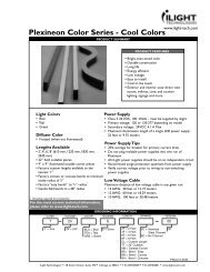
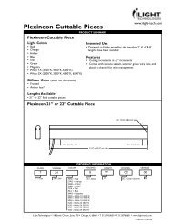
<strong>Plexineon</strong> Family Product Line2.1 Standard <strong>Plexineon</strong> Pieces<strong>Plexineon</strong> is offered in standard colors: Red, Amber, Blue,Green, and White, and specialty colors Orange and Teal.Standard <strong>Plexineon</strong> lengths are 2’, 4’, 6’ and 8’. Standard<strong>Plexineon</strong> lengths come with a metal channel (or c-channel)attached to the back for added rigidity (Fig.1). Lengthsrequiring cold bending in the field come without the c-channelaffixed to <strong>Plexineon</strong> to allow for flexibility (Fig. 2).Light ColorsRedAmberOrangeBlueGreenTealWhite (6500, 4500,3500 Kelvin temp.)MagentaPlastic Side ColorsRedYellowSilverBlueGreenWhite(white offered in silveronly)(magenta offered inblack sides only)Figure 1.Except for white and magenta, any light color can be made with any plasticside color.Figure 2.2.2 Standard <strong>Plexineon</strong> 2’ Cuttable Piece (in all colors)The 2’ Cuttable Piece is cuttable to within ¼” without any visible loss of light for red and amber. For blue,green, teal and white the piece is cuttable in nominal 2” increments. When used in conjunction with the<strong>Plexineon</strong> Standard Lengths any overall run length can be achieved. Silicone Sealant and male/female bulletconnectors are included with each Standard <strong>Plexineon</strong> 2’ Cuttable Piece. For installation instructions ofthe 2’ Cuttable Piece see section 3.10.LED ColorsCutting IncrementsRed or Amber Side A – ¼”; Side B – 2 ¾”OrangeWhite, Blue, Teal and GreenNominal 2 ¾” on either sideNominal 2” on either sideP L E X I N E O N I N S T A L L A T I O N M A D E E A S Y P A G E 4
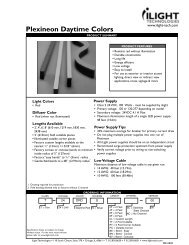
<strong>Plexineon</strong> Family Product Line2.3 Standard <strong>Plexineon</strong> 9” X 9” Outside Corner PieceThe 9” X 9” Corner Piece is used for 90 ° outside cornerinstallations (Fig. 3). (The 9” is measured on the back to theinside corner.)Figure 3.P L E X I N E O N I N S T A L L A T I O N M A D E E A S Y P A G E 5
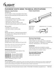
<strong>Plexineon</strong> Family Product Line2.4 <strong>Plexineon</strong> Power Supplies<strong>Plexineon</strong> is powered by low voltage class 2 power suppliesthat provide 24 VDC power to each <strong>Plexineon</strong> run. All<strong>Plexineon</strong> power supplies are UL listed. The length of runa power supply can power depends on the color of <strong>Plexineon</strong>used (see section 3.2). <strong>Plexineon</strong> power supplies areavailable for three installation applications: indoor (Fig. 4),outdoor (Fig. 5), and outdoor 3-Output power supply (notshown). The outdoor power supplies come in NEMA 3Rweatherproof enclosures.Figure 4.Part NumberPN10124DCRPN10124DCR-3RPNC224024DCR-3R120 V. Power Supply DescriptionU.S. Indoor (110 VAC)U.S. Outdoor (110 VAC)U.S. Outdoor 3-Outlet (110 VAC)Power supplies are available for 240V and 277V as specialorders.Figure 5.CAUTION: The external power unit (Figure 5) must be mounted in an upright position with the access doorlocated at the bottom. Failure to mount the unit in this position can lead to damage from the environment andvoid the warranty on the power supply.WARNING: This lighting system, including the power unit, AC cord, lead wire and <strong>Plexineon</strong> product, is not tobe installed in environmental air handling systems (e.g. the area above a drop ceiling used for supply or returnair).P L E X I N E O N I N S T A L L A T I O N M A D E E A S Y P A G E 6
<strong>Plexineon</strong> Family Product Line2.5 <strong>Plexineon</strong> Mounting Clips<strong>Plexineon</strong> pieces are held in place by specially designedstainless-steel mounting clips. There are two heights of mountingclips (Fig. 6) available: 1.25” and 1.50” tall. 1.50” clips arerecommended for <strong>Plexineon</strong> with c-channel and 1.25” arerecommended for <strong>Plexineon</strong> without c-channel. Mounting clipsare offered in bags of 50.Part NumberPNC150PNC125DescriptionMounting Clips 1.50” / StandardMounting Clips 1.25” / StandardFigure 6.<strong>iLight</strong> <strong>Technologies</strong> ships mounting clips to match the plasticcolored sides: silver, black, red, yellow, blue, white and green.2.6 Wiring14-gauge jacketed UV resistant paired wire (Fig.7) is usuallyprovided to connect the power supply to the first piece of<strong>Plexineon</strong>. This wire can also be used to connect lengths of<strong>Plexineon</strong> that are spaced greater than 4 inches from oneanother. The wire comes in 50’, 100’, 250’, and 1000’ bundles.Using 14-gauge wire, the power supply can be placed up to, butnot exceeding, 50’ away from the first length of <strong>Plexineon</strong> to bepowered and still power the maximum rated linear footage of<strong>Plexineon</strong>.Figure 7.P L E X I N E O N I N S T A L L A T I O N M A D E E A S Y P A G E 7
<strong>Plexineon</strong> <strong>Installation</strong>3.1 Layout LocationsUsing the <strong>Plexineon</strong> layout you created or the layout that <strong>iLight</strong> <strong>Technologies</strong> created for you, you have theability to place the power supplies in a variety of locations. Work with your GC or building owner to ensureappropriate placement. The power supplies may be located up to 50’ away from the first length of <strong>Plexineon</strong>if 14 gauge wire is used.It is recommended to locate two power supplies together to make installation easier. This allows you to goleft and right from one location resulting in power supply pairs being located up to 100 feet apart.Mount the power supplies and notify the electrician to provide primary power to each power supply.CAUTION: Never interconnect multiple power supplies to a single run of <strong>Plexineon</strong>. The power supplyshould be installed by a licensed electrician. <strong>Installation</strong> must be in accordance with all applicable codes,including but not limited to the National Electric Code. At no time should the output of one power supply beconnected to the output of another power supply.P L E X I N E O N I N S T A L L A T I O N M A D E E A S Y P A G E 8
<strong>Plexineon</strong> <strong>Installation</strong>3.2 Power Supply <strong>Installation</strong>Use the following guidelines for power supply use, run length, placement and installation:Power Supply UseUse indoor power supplies for indoor power installations. The indoor power supplies may be used outdoors ifthey are placed in separate NEMA 3R enclosures with a minimum of 2” clearance on all sides of each powerunit. The power cord exists the top of the power supply. Use outdoor power supplies for outdoor installations.The outdoor power supply is housed in a NEMA 3R enclosure for rain and splash protection.Use 3-outlet power supplies for indoor or outdoor installations where the 3 primary lengths of 3 individual runsmeet within 50 feet of each other. The U.S. Outdoor 3-Outlet Power Supply can handle up to 3 outlets, eachoutlet able to handle the below linear footage of product.CAUTION: The three outputs (runs) must not be connected together.Power Supply Run Length for <strong>Plexineon</strong>An <strong>iLight</strong> 24V 4A power supply can power anywhere from 1 foot up to a maximum run length of:Linear FeetColor of <strong>Plexineon</strong>48 Red, Amber or Orange32Blue, White, Green, Teal, orMagentaUnderloading a power supply does not adversely affect the system as there is no minimum load. Do notexceed the maximum run lengths for each power supply.CAUTION: The external power unit must be mounted in an upright position with the access door located atthe bottom. Failure to mount the unit in this position can lead to damage from the environment and void thewarranty on the power supply.P L E X I N E O N I N S T A L L A T I O N M A D E E A S Y P A G E 9
<strong>Plexineon</strong> <strong>Installation</strong>3.2 Wiring from Power Supply to <strong>Plexineon</strong>Cut and strip the 14-gauge wire and crimp on the male or female bullet connectors provided. Connect the malebullet connectors to the low voltage wires. The power supplies are equipped with female bullet connectors.Connect the remaining bulleted ends of the 14 gauge wires to first piece of <strong>Plexineon</strong> using the bullet/Molexadaptor. (If your product comes with bullet connectors, bullet/Molex adaptors are not necessary and notprovided.)Power Supply Distance From <strong>Plexineon</strong>Using 14 gauge paired gray wire, the maximum distance a power supply can be placed from the first piece of<strong>Plexineon</strong> in a continuous run is 50’.Larger gauge wire can be used to increase the distance from the power supply to the first piece of <strong>Plexineon</strong>.Larger gauge wire must be sourced locally.Gauge WireDistance Potential for 24V. <strong>Plexineon</strong>14 gauge 50 LF (only gauge supplied by <strong>iLight</strong>)12 gauge 75 LF10 gauge 125 LF3.3 Clip Placement<strong>Plexineon</strong> is mounted using stainless steel spring clips thatmatch the color of the plastic sides. The recommendedspacing for the clips is 2” in from each end of the <strong>Plexineon</strong>,and one or two clips in the center, based on the length of<strong>Plexineon</strong> (Fig. 8).<strong>Plexineon</strong> LengthNumber of Clips8’-0” 4 to 5 clips6’-0” 3 clips4’-0” 3 clips2’-0” or less 2 clips9” X 9” corner 3 clips (not shown)Please see diagram for clip placement.Figure 8.P L E X I N E O N I N S T A L L A T I O N M A D E E A S Y P A G E 10
<strong>Plexineon</strong> <strong>Installation</strong>3.4. Installing Mounting ClipsThe <strong>Plexineon</strong> mounting clips come with a 3/16” screw hole. It isrecommended to use exterior grade screws. If the mountingsurface is brick, stucco or concrete, a masonry anchor or insertshould be used. Slip screw inside clip and fasten tightly to surface(Fig. 9). If clips are being attached to thin metal, it isrecommended that 3/16” short rivets be used instead of screws.Clips should be mounted at an equal height to make sure <strong>Plexineon</strong>is installed straight. All clips are made of stainless steel so they willnot rust.Figure 9.NOTE: If clips are not fastened tightly, the <strong>Plexineon</strong> will not installwell.3.5 Inserting <strong>Plexineon</strong> into ClipsWhen clips are appropriately mounted, the <strong>Plexineon</strong> length can beinserted into the clips. Position the end part of <strong>Plexineon</strong> at anangle so that the bottom portion of the <strong>Plexineon</strong> is entering thelower end of the clip (Fig. 10). Push in (Fig. 11) until the clipcatches the groove (Fig. 12). Insert <strong>Plexineon</strong> one clip at a time.Make sure that all clips have caught the groove. Once the<strong>Plexineon</strong> is inserted into the clips, the <strong>Plexineon</strong> can be slid left orright for adjustment.Figure 10.NOTE: Catching the clip in the groove is important. The groove isconsidered the part between the frosted curved portion of the frontand the side plastic channel. Do not allow the clip to go over theend of the product.Figure 11.Figure 12.P L E X I N E O N I N S T A L L A T I O N M A D E E A S Y P A G E 11
<strong>Plexineon</strong> <strong>Installation</strong>3.6 <strong>Plexineon</strong> SpacingWhen installing <strong>Plexineon</strong> outside or in conditions where thetemperature might change dramatically, consider that each section willexpand or contract about 3/8” from one temperature extreme toanother. For all pieces, leave a 3/8” gap, about a finger width, betweenpieces (Fig. 13). This will allow for appropriate expansion andcontraction. This is especially important if the product is installed incooler temperatures.CAUTION: Do not butt the pieces next to each other in an outdoorapplication. This will cause service problems with expansion andcontraction.Figure 13.3.7 Connecting <strong>Plexineon</strong> Pieces<strong>Plexineon</strong> pieces are connected together using the outdoor Molex orbullet connectors. For Molex connect the male to the female. If youhave Molex connectors (shown) (Fig. 14), there are male and femaleconnectors. For bullet connectors, connect the red wire to the red wireand black to the black.NOTE: If you need to change a connector, there is an extra bag ofconnectors supplied. Only bullet connectors can be field crimped.End of Runs with Bullet ConnectorsAt the end of a run, if the <strong>Plexineon</strong> piece has two female bulletconnectors, it is fine. If the last piece has two male bullet connectorsunconnected, empty female bullet connectors must be connected overthe male connectors to prevent short circuits.Figure 14.If it is decided to cut off the wires at the end of a run, they must besealed with silicone.NOTE: If the wires are cut, this piece may not be used in other areas.It is now a permanent end piece without power pass-through.P L E X I N E O N I N S T A L L A T I O N M A D E E A S Y P A G E 12
<strong>Plexineon</strong> <strong>Installation</strong>3.8 Wire ManagementOnce the lead wires have been connected, they need to beconcealed. To conceal the lead wires twist the wires tightlytwo or three times on one side of the connectors so that thewires shorten (Fig. 15). Twist the remaining wires on theother side of the connectors and tuck between the <strong>Plexineon</strong>product and the clip or wall.NOTE: Do not allow the wires to hang out (Fig. 16). Thislooks unsightly and unprofessional. Figure 15.3.9 Installing the 9”X 9” Outside Corner PiecesThe 9”X 9” outside corner piece is designed forinstallation on 90 degree outside corners. Use 3 clips forevery corner piece. Use one clip on each 9” side and oneto the immediate left or right of the joint.Figure 16.P L E X I N E O N I N S T A L L A T I O N M A D E E A S Y P A G E 13
<strong>Plexineon</strong> <strong>Installation</strong>3.10 Using the 2’-0” Cuttable PiecesThe 2’-0” cuttable piece comes in 2’-0” lengths only that are marked “CUTTABLE.” The 2’-0” cuttable is theonly <strong>Plexineon</strong> product designed as a safe field cuttable piece.Before cutting the 2’-0” Cuttable, make sure all your standard lengths of a run have been mounted and areproperly spaced. After installing the standard lengths, the remaining gaps should be less than 2’-0”. This iswhere the 2’-0” cuttable pieces are installed.Please note that 2’-0” field cuttable pieces can be cut at different increments depending on color:• Cuttable to within ¼” increments for Red and Amber <strong>Plexineon</strong>• Cuttable to nominal 2” increments for Blue, Green, Teal and White <strong>Plexineon</strong>• Cuttable to nominal 3 7/16” increments for Orange <strong>Plexineon</strong>When used in conjunction with the <strong>Plexineon</strong> Standard Lengths any overall run length can be achieved.Silicone Sealant and male/female bullet connectors are included with each Standard <strong>Plexineon</strong> 2’ CuttablePiece.CAUTION: Make sure 2’-0” cuttable piece is fully disconnected from power before cutting.NOTE: Always cut beyond the LED groupings on the 2’-0” cuttables and trim back.P L E X I N E O N I N S T A L L A T I O N M A D E E A S Y P A G E 14
<strong>Plexineon</strong> <strong>Installation</strong> for Red and Amber 2 Foot Cuttable<strong>Installation</strong> Procedures1. Install standard <strong>Plexineon</strong> pieces first as far as they can go on the building.2. After installing the standard pieces, the remaining space in any installation should be less than 2 feet.The 2’-0” cuttable piece is intended to be field cut to fill spaces and inside corners.3. In the field, measure the remaining spaces to the nearest ¼”, disconnect power, and cut the 2’ cuttablepiece to fit. The 2’ cuttable piece when cut will be in two pieces. The primary end (End A with thepermanent metal guard) may be cut to the nearest ¼” from 24” down to 2.5” in length. The remainingpiece (End B) is a usable piece as well but will fully light only to certain lengths. These lengths areindicated on the drawing above. When lit, End B may appear “dead” up to 2 inches on the cut ends.This “dead” portion may be cut off, according to the dimensions from End B. Cutting less than thestated dimension will deaden another 2 ¾” grouping of LEDs.4. After cutting the 2’ cuttable piece, the exposed circuit on the cut end must be sealed with the providednon-conductive, non-corrosive silicone sealant.5. After cutting the 2’ cuttable piece, the exposed wires must also be cut. If the piece is to be used at theend of a run, the wires can be cut short near the permanent steel guard and sealed with silicone. If thepower will continue onto a following piece, then cut the red and black wires longer than the piece andcrimp on the provided male and female bullet connectors.6. A 16” long plastic c-channel has been provided to hold the exposed wires in place. Cut it shorter than<strong>Plexineon</strong> piece and push it against the back to hold wires.CAUTION: These dimensions are only for red and amber. Theseinstructions do not apply for blue, teal, green, white or orange cuttables.Cutting incrementsSide A: 1/4”Side B: nominal 2 3/4”P L E X I N E O N I N S T A L L A T I O N M A D E E A S Y P A G E 15
<strong>Plexineon</strong> <strong>Installation</strong> for White, Blue, Teal and Green 2 Foot Cuttable<strong>Installation</strong> Procedures1. Install standard <strong>Plexineon</strong> pieces first as far as they can go on the building.2. After installing the standard pieces, the remaining space in any installation should be less than 2 feet.The 2’-0” cuttable piece is intended to be field cut to fill spaces and inside corners.3. In the field, measure the remaining spaces to the nearest 2”, disconnect power, and cut beyond the 2”measurement. The 2’ cuttable piece when cut will be in two pieces. Each end may be cut to thenearest 2” from 24” down to 2” in length in 2” increments. Cutting on or less than the stated dimensionwill deaden 2” grouping of LEDs. The remainder piece can still be used.4. After cutting the 2’ cuttable piece, the exposed circuit on the cut end must be sealed with the providednon-conductive, non-corrosive silicone sealant.5. After cutting the 2’ cuttable piece, the exposed wires must also be cut. If the piece is to be used at theend of a run, the wires can be cut short near the permanent steel guard and sealed with silicone. If thepower will continue onto a following piece, then cut the red and black wires longer than the piece andcrimp on the provided male and female bullet connectors.6. A 16” long plastic c-channel has been provided to hold the exposed wires in place. Cut it shorter than<strong>Plexineon</strong> piece and push it against the back to hold wires.CAUTION: These dimensions are only for blue, teal, green, andwhite. These instructions do not apply for red, amber, ororange cuttables.Cutting incrementsSide A: nominal 2”Side B: nominal 2”P L E X I N E O N I N S T A L L A T I O N M A D E E A S Y P A G E 16
<strong>Plexineon</strong> <strong>Installation</strong> for Orange 2 Foot Cuttable<strong>Installation</strong> Procedures1. Install standard <strong>Plexineon</strong> pieces first as far as they can go on the building.2. After installing the standard pieces, the remaining space in any installation should be less than 2 feet.The 2’-0” cuttable piece is intended to be field cut to fill spaces and inside corners.3. In the field, measure the remaining spaces to the nearest 3 7/16”, disconnect power, and cut beyondthe 3 7/16” measurement. The 2’ cuttable piece when cut will be in two pieces. Each end may be cutto the nearest 3 7/16” (except the first length, which is 3 ½”). Cutting on or less than the stateddimension will deaden 3 7/16” grouping of LEDs. The remainder piece can still be used.4. After cutting the 2’ cuttable piece, the exposed circuit on the cut end must be sealed with the providednon-conductive, non-corrosive silicone sealant.5. After cutting the 2’ cuttable piece, the exposed wires must also be cut. If the piece is to be used at theend of a run, the wires can be cut short near the permanent steel guard and sealed with silicone. If thepower will continue onto a following piece, then cut the red and black wires longer than the piece andcrimp on the provided male and female bullet connectors.6. A 16” long plastic c-channel has been provided to hold the exposed wires in place. Cut it shorter than<strong>Plexineon</strong> piece and push it against the back to hold wires.CAUTION: These dimensions are only for orange. These instructionsdo not apply for red, amber, blue, teal, green or white cuttables.Cutting incrementsSide A: nominal 3 7/16”Side B: nominal 3 7/16”P L E X I N E O N I N S T A L L A T I O N M A D E E A S Y P A G E 17
<strong>Plexineon</strong> <strong>Installation</strong> for Red Corner 2 Foot Cuttable<strong>Installation</strong> Procedures1. Install standard <strong>Plexineon</strong> pieces first as far as they can go on the building.2. After installing the standard pieces, the remaining space in any installation should be less than 2 feet.The 2’-0” corner cuttable piece is intended to be field cut to fill spaces between a standard piece up toa corner. Another standard piece may be used to finish the appearance on the other side of the corner.3. In the field, measure the remaining space to the nearest ¼”, disconnect power, and cut the 2’ cuttablepiece to fit. The 2’ cuttable piece when cut will be in two pieces. The primary end (End A with thepermanent metal guard) may be cut to the nearest ¼” from 24” down to 3.5” in length. The remainingpiece (End B) is a usable piece as well but will fully light only to certain lengths. These lengths areindicated on the drawing above. When lit, End B may appear “dead” up to 3 inches on the cut ends.This “dead” portion may be cut off, according to the dimensions from End B. Cutting less than thestated dimension will deaden another 2 ¾” grouping of LEDs.4. After cutting the 2’ cuttable piece, the exposed circuit on the cut end must be sealed with the providednon-conductive, non-corrosive silicone sealant.5. After cutting the 2’ cuttable piece, the exposed wires must also be cut. If the piece is to be used at theend of a run, the wires can be cut short near the permanent steel guard and sealed with silicone. If thepower will continue onto a following piece, then cut the red and black wires longer than the piece andcrimp on the provided male and female bullet connectors.6. A 16” long plastic c-channel has been provided to hold the exposed wires in place. Cut it shorter than<strong>Plexineon</strong> piece and push it against the back to hold wires.CAUTION: These dimensions are only for red and amber. Theseinstructions do not apply for blue, teal, green, white or orange cuttables.Cutting incrementsSide A: 1/4”Side B: nominal 2 3/4”P L E X I N E O N I N S T A L L A T I O N M A D E E A S Y P A G E 18
<strong>Installation</strong> Tips4.1 TimerWhen installing <strong>Plexineon</strong>, it is beneficial to add a timer or a photo cell switch to shut the <strong>Plexineon</strong> off duringthe day to increase the lifetime of the product and save energy.4.2 Power Up While InstallingIf possible, light each piece of <strong>Plexineon</strong> as you go. This way it is ensured that you have working product thathas been connected properly.4.3 Start in the Corners (if you have 9” X 9” corner pieces)When starting the <strong>Plexineon</strong> install, it is recommended to start from the outside corners and work your way toan inside corner or the end of a run.• If there are 9” X 9” corner pieces, start by installing those first.• Continue with the longer pieces (typically 8’-0”, 6’-0”, 4’-0”, and 2’-0”)• Do your 2’-0” Cuttables last.If you have red 2’-0” cuttable corners start in the back of the run or the inside corner and move towardsthe outside corner.4.4 Storing <strong>Plexineon</strong> Until InstalledKeep <strong>Plexineon</strong> from excessive heat and out of direct sunlight prior to installation. In some cases, if <strong>Plexineon</strong>is exposed to excessive sun it may experience slight bowing. The product can be installed even in a bowedcondition. Just make sure the clips have properly grabbed the groove.4.5 SpacingBe sure that 3/8” space is made between all <strong>Plexineon</strong> pieces for all installations.P L E X I N E O N I N S T A L L A T I O N M A D E E A S Y P A G E 19
Addendum: Using Molex Connectors with Interior Power SupplyP L E X I N E O N I N S T A L L A T I O N M A D E E A S Y P A G E 21
Addendum: Using Molex Connectors with Exterior Power SupplyCAUTION: The external power unit must be mounted in an upright position with the access door located atthe bottom. Failure to mount the unit in this position can lead to damage from the environment and void thewarranty on the power supply.P L E X I N E O N I N S T A L L A T I O N M A D E E A S Y P A G E 22
Addendum: Using Molex Connectors with Two Foot CuttablesNote: After cutting product and buss wire at desired length, crimp on appropriate male or female connectorsto Molex adaptors.P L E X I N E O N I N S T A L L A T I O N M A D E E A S Y P A G E 23