Installation and Operation Manual - MagTek
Installation and Operation Manual - MagTek
Installation and Operation Manual - MagTek
You also want an ePaper? Increase the reach of your titles
YUMPU automatically turns print PDFs into web optimized ePapers that Google loves.
TABLE OF CONTENTSSECTION 1. OVERVIEW ............................................................................................... 1FEATURES ............................................................................................................................................... 2ACCESSORIES ........................................................................................................................................ 2SPECIFICATIONS .................................................................................................................................... 3SECTION 2. INSTALLATION ........................................................................................ 5REQUIREMENTS ..................................................................................................................................... 5CABLING PROCEDURE .......................................................................................................................... 6SECTION 3. OPERATION ............................................................................................. 9CHECK READING PROCEDURE ............................................................................................................ 9CARD READING PROCEDURE ............................................................................................................ 10LED INDICATORS .................................................................................................................................. 11CLEANING ............................................................................................................................................. 11Opening the Unit ................................................................................................................................. 12Cleaning Check Path <strong>and</strong> Scan Bars ................................................................................................. 13Closing the Unit .................................................................................................................................. 17SECTION 4. TROUBLESHOOTING GUIDE ................................................................ 19REQUIREMENTS ................................................................................................................................... 19SET-UP ................................................................................................................................................... 19TROUBLESHOOTING ............................................................................................................................ 19APPENDIX A. CHECK READING ............................................................................... 25E13-B CHARACTER SET ...................................................................................................................... 25CMC-7 CHARACTER SET ..................................................................................................................... 25SI SII SIII SIV S5 ........................................................................................................... 25CHECK LAYOUTS ................................................................................................................................. 26MICR FIELDS ......................................................................................................................................... 271-Transit Field ..................................................................................................................................... 272-On-Us Field ..................................................................................................................................... 283-Amount Field ................................................................................................................................... 284-Auxiliary On-Us Field ...................................................................................................................... 28APPENDIX B. DEMO SOFTWARE AND USB DRIVERS ........................................... 29vii
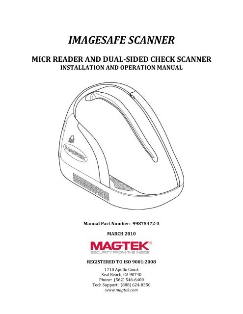
SECTION 1. OVERVIEWThe ImageSafe Scanner is a single-feed MICR (Magnetic Ink Character Recognition) reader<strong>and</strong> a dual-sided check scanner. In a single pass, the ImageSafe Scanner reads the MICRcharacters at the bottom of a check <strong>and</strong> produces a digitized image of the entire check (front <strong>and</strong>back). The characters <strong>and</strong> the image are then transmitted to a host device which is typically a PC.The ImageSafe Scanner also offers an integrated MagneSafe secure card reader to secure cardbased payment transactions by encrypting the encoded card holder date on debit, credit <strong>and</strong> giftcards. The MagneSafe reader can be used with a magstripe card for 2-factor authenticationduring web based financial transactions. The MagneSafe reader will auto-discriminate betweendifferent card formats such as: ISO (International St<strong>and</strong>ards Organization) or AAMVA(American Association of Motor Vehicle Administrators).Figure 1-1. ImageSafe Scanner <strong>and</strong> Dual-sided Scanner with MagneSafe Secure Reader1
Section 1. OverviewSPECIFICATIONSTable 1-2 lists the specifications for the ImageSafe Scanner.Table 1-2. SpecificationsOPERATINGReference St<strong>and</strong>ards ANSI X9.27Power Input12VDC, 1.5 AmpCurrent(Operating Idle)300 mA1.5 A MaxMTBF Electronics: 125,000 hoursCheck Read Head: 1,000,000 passesMSR Read head: 1,000,000 passesDocument Speed 10 ipsDocument Size 4"x 9" Maximum3"x 2.625" MinimumImage Resolution 200 dpiMICR fonts supported E13-BCMC-7Interface Options USB 2.0 or USB 1.1MECHANICALDimensions Length 9.0”, Width 3.9”, Height 6.0”Weight:2.2 lbs.Connector:USB BENVIRONMENTALTemperatureOperating 0 o C to 50 o C (32 o F to 122 o F)Storage -30 o C to 70 o C (-22 o F to 158 o F)HumidityOperating 10% to 90% non-condensingStorage Up to 100% non-condensingAltitudeOperatingStorage0 -10,000 ft (0 - 3,048m)0 - 50,000 ft (0 - 15240m)3
ImageSafe4
SECTION 2. INSTALLATION<strong>Installation</strong> of the ImageSafe Scanner is described below figure 2-1 shows a cad being swipedthrough the MagneSafe card reader.Note: Install the ImageSafe software before connecting the ImageSafe Scanner to a computer.Failure to perform this step will prevent the ImageSafe application from installingproperly.Figure 2-1. ImageSafe Component IdentificationREQUIREMENTSThe following items should be present in ImageSafe Scanner box <strong>and</strong> will be required forinstallation:• ImageSafe Scanner• Hi-Speed USB Cable• Power Adapter• <strong>Installation</strong> software CD (optional)5
ImageSafeCABLING PROCEDURETo connect the ImageSafe Scanner to a local computer locate the power <strong>and</strong> USB cablescontained in the box. Once the cables have been located perform the following steps:1. Connect the USB plug to the ImageSafe Scanner as shown in Figures 2-2 <strong>and</strong> 2-4.2. On the AC power adapter, connect the power plug to the device3. On the AC power adapter, connect the plug to wall outlet4. The LED indicator on the ImageSafe Scanner should turn on to a steady green. TheLED indicator on the ImageSafe Scanner is located on the slot where the check is firstinserted for reading (see figure 2.1). If the LED does not turn green refer to the LEDindication section.CautionDo not place the ImageSafe Scanner within 6 inches of acomputer monitor or power supply. These devices may causeundesirable interference with the check reading operation.Figure 2-2. ImageSafe Cabling (U.S. Version)6
Section 2. <strong>Installation</strong>Figure 2-3. ImageSafe Cabling (International Version)Figure 2-4. ImageSafe ConnectionsNote: An optional strain relief clip can be installed to securely attach the USB <strong>and</strong> power supplycable to the ImageSafe chassis. To install the clip insert the cables into the retaining clip<strong>and</strong> then plug the clip with cables into the ImageSafe. Figure 2-5, indicates the correctlocation for each cable.7
ImageSafeFigure 2-5. ImageSafe Cable Clip8
SECTION 3. OPERATIONThis section contains check/ card reading procedures, the LED indicator states <strong>and</strong> cleaningprocedures.CHECK READING PROCEDURE1. Orient the check so the MICR line is down <strong>and</strong> the printed side faces the center of theImageSafe Scanner as indicated in Figure 3-1. For more information about the MICRline refer to Appendix A.2. Place the check so the leading edge is in the open slot. Slide the check forward.3. When the ImageSafe Scanner detects the presence of the check, the motor will turnon. At this time press the check forward until the unit grabs the check. When thishappens, release the check. The check will then be transported around the check path<strong>and</strong> will exit through the other side.4. After the check is read, the ImageSafe Scanner will transmit the data as specified byits configuration parameters.5. Remove the check.Figure 3-1. Check Orientation - Insertion9
ImageSafeOpening the UnitTo open the check path <strong>and</strong> gain access to the Scan Bars, grip the ImageSafe Scanner hold theunit as shown in Figure 3-3. Press the access latch button with your thumb <strong>and</strong> the access doorwill pop open.Figure 3-3. Opening the Unit12
Section 3. <strong>Operation</strong>Cleaning Check Path <strong>and</strong> Scan Bars1. When the check path access door is open, as shown in Figure 3-4, check the path fordebris. To clean, turn the unit over <strong>and</strong> tap gently on the bottom.Figure 3-4. Cleaning Check Path <strong>and</strong> Scan Bars2. Check the scan bars to ensure there is no build-up of ink or paper debris.13
ImageSafe3. To clean the scan bars, use the cleaning swab, shown in Figure 3-5. Activate the swabby bending the plastic tube until you hear a snap.4. Wait until the liquid moves into the sponge tip. It should be damp when touched.Figure 3-5. Activating the Cleaning Swab14
Section 3. <strong>Operation</strong>5. When the tip of the swab is damp, clean the first scan bar by wiping the swab up <strong>and</strong>down the scan bar surface as indicated in Figure 3-6.Figure 3-6. Cleaning the First Scan Bar15
ImageSafe6. After cleaning the first scan bar, clean the second scan bar by again wiping the swabup <strong>and</strong> down the scan bar surface as indicated in Figure 3-7.Figure 3-7. Cleaning the Second Scan Bar16
Section 3. <strong>Operation</strong>Closing the Unit1. Hold the unit as shown in Figure 3-8. Push the rear access door closed with the righth<strong>and</strong> while holding on the opposite side with the left h<strong>and</strong>.2. The unit is properly closed when the two panels are flush <strong>and</strong> the latch has "clicked"into position.Figure 3-8. Closing the Unit17
ImageSafe18
SECTION 4. TROUBLESHOOTING GUIDEREQUIREMENTS• Personal Computer.• USB Interface Cable, Part Number: 22350300• AC adapter, Part Number: 64300090 (U.S) or 64300080 (International)• Sample checks, Part Number: 96530005.SET-UP1. Plug USB cable into the ImageSafe Scanner.2. Plug the other end of the USB cable into the PC.3. Power on the ImageSafe Scanner.4. Start trouble-shooting procedure at Step 00.TROUBLESHOOTING00 Check LEDCheck the status of the LED indicator:◊ Off, continue to step 01.◊ Green, continue to step 02.◊ Blinking red, continue to step 07.◊ Red, continue to step 12.01 Check the Power to the ImageSafe ScannerPossible causes for this problem are:• AC adapter connection to outlet - make sure the AC adapter is securely connected to outleton the wall or power strip.• AC adapter connection to ImageSafe Scanner - make sure the AC adapter is securelyconnected to the power jack on the Cable.• Power strip - if using a power strip, make sure the strip is connected to outlet on the wall <strong>and</strong>the switch on the strip is turned on.• AC adapter is defective - replace the AC adapter.Determine if any of the conditions described above are true:◊ If yes, rectify <strong>and</strong> continue to step 00.◊ If no, continue to step 12.02 Read a checkRead a check through the ImageSafe Scanner:◊ If the check is transported all the way around the check path, continue to step 03.19
ImageSafe◊ If the check gets "stuck" in the check path, continue to step 06.◊ If the motor does not turn on, continue to step 12.03 Did PC receive data?After the check is read, did the PC receive any data?◊ If yes, continue to step 04.◊ If no, verify that USB cable is connected04 Analyze dataAnalyze the data received by the PC:◊ If the data is good, continue to step 10.◊ If the data contains one or more '?', continue to step 05.05 Read errorPossible causes for this problem are:• Interference - the ImageSafe may be too close to a monitor, AC adapter or magnetic device.Move the ImageSafe away from the source of interference.• Printing problem - the check being read may not meet the requirements of the ANSISt<strong>and</strong>ards. Use one the sample checks provided by <strong>MagTek</strong>.• Feeding the check - do not hold on to the check as it goes around the path. Release the checkimmediately after the ImageSafe "grabs" it. Also, make sure that the front end is not tilted upwhile the check is being read.Determine if any of the conditions described above are true:◊ If yes, rectify <strong>and</strong> continue to step 02.◊ If no, continue to step 06.20
Section 4. Troubleshooting Guide06 Path is obstructedForeign debris obstructing the check path:• Loose debris - power off the ImageSafe Scanner <strong>and</strong> refer to Section 3, Check Path Cleaning.• Wedged debris - the debris is wedged in <strong>and</strong> cannot be removed with the procedure describedabove.Is the foreign debris removable?◊ If yes, remove <strong>and</strong> continue to step 02.◊ If no, continue to step 12.07 Blocked sensor or data errorOne of the sensors may be blocked by dust build-up or foreign debris (see Figure 4-1 for sensorlocation) or an error occurred when the MICR\card data was read. To resolve the issue tryreinserting the check or re-swiping the card if this does not work process to the sensor.Use canned air to clean the sensor if this does not work proceed with the steps below.Power off the ImageSafe Scanner <strong>and</strong> then power on again, observe the LED indicator:◊ If the LED indicator blinks red, continue to step 12.◊ Any other LED indicator status, continue to step 00.◊ If the LED indicator blinks red/green, continue to step 12.◊ Any other LED indicator status, continue to step 00.Figure 4-1. Sensor Location21
ImageSafe08 No MICR data detectedPossible causes for this problem are:• No MICR characters - the ink used to print the MICR characters does not have magneticproperties. Try one of the sample checks provided by <strong>MagTek</strong>.• Feeding the check - When feeding the check, make sure that the MICR line is at the bottom<strong>and</strong> the printed side of the check is facing the <strong>MagTek</strong> logo on the ImageSafe Scanner.Determine if any of the conditions described above are true:◊ If yes, rectify <strong>and</strong> continue to step 02.◊ If no, continue to step 09.09 Cable problemPossible causes for this problem are:• Loose connection - the cable connector on the PC or the ImageSafe Scanner may be loose.Make sure that both connectors are tightly connected.• Damaged cable - the connectors, pins or wires in the cable may be damaged. Replace cable.Determine if any of the conditions described above are true:◊ If yes, rectify <strong>and</strong> continue to step 02.◊ If no, continue to step 12.10 No problem foundThe ImageSafe Scanner is operating properly. If you have additional concerns or requirementsplease contact your <strong>MagTek</strong> representative.11 Read Insta-Change checkRead Insta-Change check with the appropriate settings. Return to step 00. If condition persists,continue to step 12.22
Section 4. Troubleshooting Guide12 Return ImageSafe Scanner to <strong>MagTek</strong>Possible causes for this problem are:• USB cable is not connected• The computer is turned off• Sensor board is damaged• Power connection failureThe ImageSafe Scanner has a problem that needs further analysis, testing, <strong>and</strong> possibly repair.Please contact the <strong>MagTek</strong> Help Desk at (888) 624-8350, <strong>and</strong> make arrangements to send theunit back to <strong>MagTek</strong>. Include a detailed description of the problem.23
ImageSafe24
APPENDIX A. CHECK READINGThe characters printed on the bottom line of commercial <strong>and</strong> personal checks are special. Theyare printed with magnetic ink to meet specific st<strong>and</strong>ards. These characters can be read by aMICRImage Reader at higher speeds <strong>and</strong> with more accuracy than manual data entry. TwoMICR character sets are used worldwide; they are: E13-B <strong>and</strong> CMC-7. The E13-B set is used inthe US, Canada, Australia, United Kingdom, Japan, India, Mexico, Venezuela, Colombia, <strong>and</strong>the Far East. The CMC-7 set is used in France, Spain, other Mediterranean countries, <strong>and</strong> mostSouth American countries.E13-B CHARACTER SETThe MICR font character set E13-B includes digits 0 through 9 <strong>and</strong> four symbols. The numbersfound on U.S. checks are of the E13-B character set. The numbers <strong>and</strong> symbols of E13-B are asfollows:Transit symbolDash SymbolOn-Us SymbolAmount SymbolCMC-7 CHARACTER SETThe numbers <strong>and</strong> symbols of the CMC-7 character set are as follows:SI SII SIII SIV S525
ImageSafeThe nonnumeric CMC-7 characters are translated by the ImageSafe Scanner as shown in TableA-1.Table A-1. CMC-7 Nonnumeric CharactersCMC-7 CharacterSISIISIIISIVSVMICRImage ReaderOutputABCDECHECK LAYOUTSPersonal checks with MICR fields are shown in Figure A-1. Business checks are shown inFigure A-2. The digits 1 through 4 in the illustrations are described below under MICR Fields.6.00”2.75”1 2 3Figure A-1. Personal Checks26
Appendix A. Check Reading8.75”3.67”41 2 3Figure A-2. Business ChecksMICR FIELDSThe numbers 1 through 4 refer to the numbers below the checks on the illustration <strong>and</strong> representthe 4 MICR fields.1-Transit FieldThe Transit field is a 9-digit field bracketed by two Transit symbols. The field is subdivided asfollows:• Digits 1-4• Digits 5-8• Digit 9Federal Reserve Routing NumberBank ID Number (American Banking Association)Check Digit27
ImageSafe2-On-Us FieldThe On-Us field is variable, up to 19 characters (including symbols). Valid characters are digits,spaces, dashes, <strong>and</strong> On-Us symbols. The On-Us field contains the account number <strong>and</strong> may alsocontain a serial number (Check number) <strong>and</strong>/or a transaction code. Note that an On-Us symbolmust always appear to the right of the account number.3-Amount FieldThe Amount field is a 10-digit field bracketed by Amount symbols. The field is always zerofilledto the left.4-Auxiliary On-Us FieldThe Auxiliary On-Us field is variable, 4-10 digits, bracketed by two On-Us symbols. This fieldis not present on personal checks. On business checks, this field contains the check serialnumber.28
APPENDIX B. DEMO SOFTWARE AND USB DRIVERSTo install the ImageSafe Scanner USB drivers <strong>and</strong> Demo software follow the steps below:1. Insert the installation software CD into your computer’s CD-ROM (or download softwaredirectly from the <strong>MagTek</strong> website: www.magtek.com); the installation application willautomatically begin <strong>and</strong> the screen below will appear. Press [Next] to continue theinstallation process.29
ImageSafe2. At the “Select Options” screen shown below check the options you wish to install <strong>and</strong>press [Next] to proceed with the installation.3. The next step in to select the software installation location. Press [Browse] to select alocation or press [Next] to except the default location <strong>and</strong> proceed with the installation.30
Appendix B. Demo Software <strong>and</strong> USB Drivers4. The ImageSafe software is now installed press [Finish] to complete the installationprocess.31
ImageSafeOnce the demo software has been successful loaded the ImageSafe demo program can be used.To use the demo program, click on the Microsoft Windows Start button. Then navigate to thedemo program by clicking on: All Prorgams→<strong>MagTek</strong>→Excella <strong>and</strong> Excella STX→DemoProgram. When the Demo program is selected the window below will be shown.Select ‘Excella MDX.MDX001” from the [Select Device] drop down menu as shown below <strong>and</strong>press connect; the demo software is now ready to use simply insert a check or swipe a card.32
Notes:33


