

Rotary Motion Accessory Pack - Serrata Science Equipment
Rotary Motion Accessory Pack - Serrata Science Equipment
Rotary Motion Accessory Pack - Serrata Science Equipment

Create successful ePaper yourself
Turn your PDF publications into a flip-book with our unique Google optimized e-Paper software.
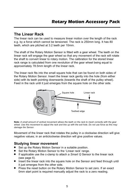
<strong>Rotary</strong> <strong>Motion</strong> <strong>Accessory</strong> <strong>Pack</strong>The Linear RackThe linear rack can be used to measure linear motion over the length of the racke.g. by a force which cannot be tensioned. The rack is 250mm long. It has 80teeth, which are pitched at 3.2 teeth per 10mm.The shaft of the <strong>Rotary</strong> <strong>Motion</strong> Sensor is fitted with a gear wheel. The teeth on thelinear rack will engage the gear wheel so that any movement of the rack will rotatethe shaft to convert linear to rotary motion. The calibration for the stored linearrack range is calculated from one revolution of the gear wheel being equal toapproximately 78.5mm length of the linear rack.The linear rack fits into the small square hole that can be found on both sides ofthe <strong>Rotary</strong> <strong>Motion</strong> Sensor. Insert the linear rack gently into the hole (from eitherside) with its teeth pointing downwards (towards the shaft of the pulley wheel).Feed in the rack until it just emerges from the square hole on the other side.Square holeLinear rackToothed edgeNote: A small amount of vertical movement allows the teeth on the rack to mesh correctly with the gearwheel. Use this movement to adjust the rack and line up with the exit hole. Do not use force as this maydamage the Sensor.Movement of the linear rack that rotates the pulley in a clockwise direction will givenegative values; in an anticlockwise direction will give positive values.Studying linear movementSet up the <strong>Rotary</strong> <strong>Motion</strong> Sensor in a suitable position.Set the <strong>Rotary</strong> <strong>Motion</strong> Sensor to the ‘Linear rack’ range.If applicable use the c-clamp to attach a Smart Q Sensor to the linear rack(see page 6).Insert the linear rack into the square hole on the Sensor and feed through untilit just emerges from the other side.Press the reset button on the <strong>Rotary</strong> <strong>Motion</strong> Sensor to set zero. If an exact0mm start point is required manually adjust the rack to a zero reading.5


