BLF878 UHF power LDMOS transistor - NXP Semiconductors
BLF878 UHF power LDMOS transistor - NXP Semiconductors
BLF878 UHF power LDMOS transistor - NXP Semiconductors

You also want an ePaper? Increase the reach of your titles
YUMPU automatically turns print PDFs into web optimized ePapers that Google loves.
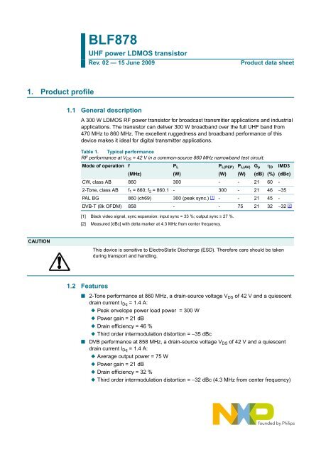
<strong>NXP</strong> <strong>Semiconductors</strong><strong>BLF878</strong><strong>UHF</strong> <strong>power</strong> <strong>LDMOS</strong> <strong>transistor</strong>4. Limiting values5. Thermal characteristicsTable 4. Limiting valuesIn accordance with the Absolute Maximum Rating System (IEC 60134).Symbol Parameter Conditions Min Max UnitV DS drain-source voltage - 89 VV GS gate-source voltage −0.5 +11 VT stg storage temperature −65 +150 °CT j junction temperature - 200 °CTable 5.6. CharacteristicsThermal characteristicsSymbol Parameter Conditions Typ UnitR th(j-c) thermal resistance from junction to case T case =80°C; [1] 0.23 K/WP L(AV) = 150 WR th(c-h) thermal resistance from case to heatsink[2]0.15 K/W[1] R th(j-c) is measured under RF conditions.[2] R th(c-h) is dependent on the applied thermal compound and clamping/mounting of the device.Table 6. CharacteristicsT j =25°C unless otherwise specified.Symbol Parameter Conditions Min Typ Max UnitV (BR)DSS drain-source breakdown voltage V GS =0V; I D = 2.25 mA [1] 89 - 105.5 VV GS(th) gate-source threshold voltage V DS = 10 V; I D = 225 mA [1] 1.4 1.9 2.4 VI DSS drain leakage current V GS =0V; V DS =42V - - 1.4 µAI DSX drain cut-off current V GS =V GSth + 3.75 V; 35 39 - AV DS =10VI GSS gate leakage current V GS =11V; V DS = 0 V - - 140 nAg fs forward transconductance V DS =10V; I D = 11.2 A[1]- 15.5 - SR DS(on) drain-source on-state resistance V GS =V GSth + 3.75 V; [1] - 110 - mΩI D = 7.6 AC iss input capacitance V GS = 0 V; V DS =40V; [2] - 190 - pFf=1MHzC oss output capacitance V GS = 0 V; V DS =40V; [2] - 60 - pFf=1MHzC rss reverse transfer capacitance V GS = 0 V; V DS =40V;f=1MHz[2] - 2 - pF[1] I D is the drain current.[2] Capacitance values without internal matching.<strong>BLF878</strong>_2© <strong>NXP</strong> B.V. 2009. All rights reserved.Product data sheet Rev. 02 — 15 June 2009 3 of 18
<strong>NXP</strong> <strong>Semiconductors</strong><strong>BLF878</strong><strong>UHF</strong> <strong>power</strong> <strong>LDMOS</strong> <strong>transistor</strong>7.1 Narrowband RF figures7.1.1 CW24G p(dB)2220(2)(1)G p(2)η D(1)001aai076806040η D(%)18201600 100 200 300 400P L (W)I Dq = 1.4 A; measured in a common source narrowband 860 MHz test circuit.(1) V DS = 40 V(2) V DS = 42 VFig 2. CW <strong>power</strong> gain and drain efficiency as a function of load <strong>power</strong>; typical values<strong>BLF878</strong>_2© <strong>NXP</strong> B.V. 2009. All rights reserved.Product data sheet Rev. 02 — 15 June 2009 5 of 18
<strong>NXP</strong> <strong>Semiconductors</strong><strong>BLF878</strong><strong>UHF</strong> <strong>power</strong> <strong>LDMOS</strong> <strong>transistor</strong>7.1.3 DVB-T23001aai07960−15001aai080G p(dB)(2)(1)η D(%)IMD3(dBc)21G p40−25η D(1)(2)1920−35(1)(2)1700 50 100 150 200 250P L(AV) (W)I Dq = 1.4 A; measured in a common source narrowband860 MHz test circuit.(1) V DS = 40 V(2) V DS = 42 VFig 5. DVB-T <strong>power</strong> gain and drain efficiency asfunctions of average load <strong>power</strong>; typicalvaluesFig 6.−450 50 100 150 200 250P L(AV) (W)I Dq = 1.4 A; measured in a common source narrowband860 MHz test circuit.(1) V DS = 40 V(2) V DS = 42 VDVB-T third order intermodulation distortionas a function of average load <strong>power</strong>; typicalvalues<strong>BLF878</strong>_2© <strong>NXP</strong> B.V. 2009. All rights reserved.Product data sheet Rev. 02 — 15 June 2009 7 of 18
<strong>NXP</strong> <strong>Semiconductors</strong><strong>BLF878</strong><strong>UHF</strong> <strong>power</strong> <strong>LDMOS</strong> <strong>transistor</strong>7.2 Broadband RF figures7.2.1 2-Tone22001aai081800001aai082G p(dB)G p(2)(1)η D(%)IMD3(dBc)1860−20η D(1)(2)(1)(2)1440−401020400 500 600 700 800 900f (MHz)P L(AV) = 150 W; I Dq = 1.4 A; measured in a commonsource broadband test circuit as described in Section 8.(1) V DS = 40 V(2) V DS = 42 VFig 7. 2-Tone <strong>power</strong> gain and drain efficiency as afunction of frequency; typical valuesFig 8.−60400 500 600 700 800 900f (MHz)P L(AV) = 150 W; I Dq = 1.4 A; measured in a commonsource broadband test circuit as described in Section 8.(1) V DS = 40 V(2) V DS = 42 V2-Tone third order intermodulation distortionas a function of frequency; typical values<strong>BLF878</strong>_2© <strong>NXP</strong> B.V. 2009. All rights reserved.Product data sheet Rev. 02 — 15 June 2009 8 of 18
<strong>NXP</strong> <strong>Semiconductors</strong><strong>BLF878</strong><strong>UHF</strong> <strong>power</strong> <strong>LDMOS</strong> <strong>transistor</strong>7.2.2 DVB-T22001aai083600001aai084G p(dB)G p(2)(1)η D(%)IMD3(dBc)18η D(1)(2)40−20(1)(2)1420−40100400 500 600 700 800 900f (MHz)P L(AV) = 77 W; I Dq = 1.4 A; measured in a commonsource broadband test circuit as described in Section 8.(1) V DS = 40 V(2) V DS = 42 VFig 9. DVB-T <strong>power</strong> gain and drain efficiency asfunctions of frequency; typical valuesFig 10.−60400 500 600 700 800 900f (MHz)P L(AV) = 77 W; I Dq = 1.4 A; measured in a commonsource broadband test circuit as described in Section 8.(1) V DS = 40 V(2) V DS = 42 VDVB-T third order intermodulation distortionas a function of frequency; typical values10PAR(dB)9001aai085(2)(1)8765400 500 600 700 800 900f (MHz)P L(AV) = 77 W; I Dq = 1.4 A; measured in a common source broadband test circuit as described in Section 8.PAR of input signal = 9.5 dB at 0.01 % probability on CCDF.(1) V DS = 40 V(2) V DS = 42 VFig 11. DVB-T PAR at 0.1 % and at 0.01 % probability on the CCDF as function of frequency; typical values<strong>BLF878</strong>_2© <strong>NXP</strong> B.V. 2009. All rights reserved.Product data sheet Rev. 02 — 15 June 2009 9 of 18
<strong>NXP</strong> <strong>Semiconductors</strong><strong>BLF878</strong><strong>UHF</strong> <strong>power</strong> <strong>LDMOS</strong> <strong>transistor</strong>7.3 Ruggedness in class-AB operationThe <strong>BLF878</strong> is capable of withstanding a load mismatch corresponding to VSWR = 10 : 1through all phases under the following conditions: V DS = 42 V; f = 860 MHz at rated<strong>power</strong>.7.4 Impedance informationdrainZ LZ igate001aai086Fig 12.Definition of <strong>transistor</strong> impedanceTable 8. Typical push-pull impedanceSimulated Z i and Z L device impedance; impedance info at V DS = 42 V and P L(PEP) = 300 W.f Z i Z LMHz Ω Ω300 0.933 − j1.376 6.431 − j4.296325 0.959 − j0.986 6.889 − j3.911350 0.988 − j0.628 7.237 − j3.476375 1.020 − j0.295 7.475 − j3.017400 1.057 + j0.017 7.610 − j2.559425 1.097 + j0.314 7.652 − j2.120450 1.143 + j0.598 7.614 − j1.713475 1.194 + j0.871 7.512 − j1.348500 1.251 + j1.137 7.359 − j1.031525 1.315 + j1.397 7.168 − j0.762550 1.388 + j1.652 6.949 − j0.542575 1.470 + j1.903 6.712 − j0.368600 1.563 + j2.152 6.465 − j0.237625 1.668 + j2.398 6.214 − j0.145650 1.788 + j2.642 5.962 − j0.089675 1.925 + j2.885 5.714 − j0.064700 2.082 + j3.125 5.472 − j0.066725 2.262 + j3.362 5.238 − j0.093750 2.470 + j3.594 5.012 − j0.141775 2.711 + j3.816 4.796 − j0.207800 2.989 + j4.025 4.590 − j0.289825 3.310 + j4.213 4.394 − j0.385850 3.680 + j4.369 4.208 − j0.493875 4.103 + j4.478 4.031 − j0.611900 4.580 + j4.519 3.864 − j0.737<strong>BLF878</strong>_2© <strong>NXP</strong> B.V. 2009. All rights reserved.Product data sheet Rev. 02 — 15 June 2009 10 of 18
<strong>NXP</strong> <strong>Semiconductors</strong><strong>BLF878</strong><strong>UHF</strong> <strong>power</strong> <strong>LDMOS</strong> <strong>transistor</strong>Table 8. Typical push-pull impedance …continuedSimulated Z i and Z L device impedance; impedance info at V DS = 42 V and P L(PEP) = 300 W.f Z i Z LMHz Ω Ω925 5.103 + j4.467 3.706 − j0.871950 5.656 + j4.291 3.556 − j1.011975 6.205 + j3.963 3.415 − j1.1571000 6.696 + j3.463 3.281 − j1.3087.5 Reliability10 6Years10 5001aai08710 410 310 210(1)(2)(3)(4)(5)(6)(7)(8)(9)(10)(11)10 4 812162024I DS(DC) (A)TTF (0.1 % failure fraction).The reliability at pulsed conditions can be calculated as follows: TTF (0.1 %) × 1 / δ.(1) T j = 100 °C(2) T j = 110 °C(3) T j = 120 °C(4) T j = 130 °C(5) T j = 140 °C(6) T j = 150 °C(7) T j = 160 °C(8) T j = 170 °C(9) T j = 180 °C(10) T j = 190 °C(11) T j = 200 °CFig 13. <strong>BLF878</strong> electromigration (I DS(DC) , total device)<strong>BLF878</strong>_2© <strong>NXP</strong> B.V. 2009. All rights reserved.Product data sheet Rev. 02 — 15 June 2009 11 of 18
<strong>NXP</strong> <strong>Semiconductors</strong><strong>BLF878</strong><strong>UHF</strong> <strong>power</strong> <strong>LDMOS</strong> <strong>transistor</strong>8. Test informationTable 9. List of componentsFor test circuit, see Figure 14, Figure 15 and Figure 16.Component Description Value RemarksB1, B2 semi rigid coax 25 Ω; 43.5 mm EZ90-25-TPC1, C2 multilayer ceramic chip capacitor 8.2 pF[1]C3, C9 multilayer ceramic chip capacitor 3.9 pF[2]C4 multilayer ceramic chip capacitor 2.7 pF[2]C5, C7, C8 multilayer ceramic chip capacitor 6.8 pF[1]C6 multilayer ceramic chip capacitor 2.2 pF[2]C10 multilayer ceramic chip capacitor 47 pF[2]C11, C12 multilayer ceramic chip capacitor 100 pF[1]C13, C14 multilayer ceramic chip capacitor 100 pF[2]C15, C16 multilayer ceramic chip capacitor 10 µF TDK C570X7R1H106KT000N orcapacitor of same quality.C17, C18 electrolytic capacitor 470 µF; 63 VC20 multilayer ceramic chip capacitor 15 pF[3]C21 trimmer 0.6 pF to 4.5 pF TekelecC22 multilayer ceramic chip capacitor 11 pF[3]C23 multilayer ceramic chip capacitor 3.9 pF[3]C24 multilayer ceramic chip capacitor 4.7 pF[3]C25, C26, C27 multilayer ceramic chip capacitor 100 pF[3]C28, C29 multilayer ceramic chip capacitor 560 pF[2]C30, C31 electrolytic capacitor 10 µFL1 stripline -[4](W × L) 24 mm × 13 mmL2 stripline -[4](W × L) 15 mm × 24.5 mmL3 stripline -[4](W × L) 5 mm × 21 mmL4 stripline -[4](W × L) 2.4 mm × 6mmL5, L23 stripline -[4](W × L) 2 mm × 43.5 mmL6 stripline -[4](W × L) 2 mm × 4.5 mmL7 stripline -[4](W × L) 5.5 mm × 24 mmL20 stripline -[4] (W × L) 15 mm × 5mmL21 stripline -[4] (W × L) 3 mm × 39 mmL22 stripline -[4] (W × L) 2.4 mm × 5.7 mmR1, R2 resistor 5.6 Ω long wiresR3, R4 potentiometer 10 kΩR5, R6 resistor 10 kΩR7, R8 resistor 1 kΩ[1] American technical ceramics type 180R or capacitor of same quality.[2] American technical ceramics type 100B or capacitor of same quality.[3] American technical ceramics type 100A or capacitor of same quality.[4] Printed-Circuit Board (PCB): Rogers 5880; ε r = 2.2 F/m; height = 0.79 mm; Cu (top/bottom metallization);thickness copper plating = 35 µm.<strong>BLF878</strong>_2© <strong>NXP</strong> B.V. 2009. All rights reserved.Product data sheet Rev. 02 — 15 June 2009 12 of 18
<strong>NXP</strong> <strong>Semiconductors</strong><strong>BLF878</strong><strong>UHF</strong> <strong>power</strong> <strong>LDMOS</strong> <strong>transistor</strong>+ V G1(test)+ V D1(test)R7R3C13R5C30C15C17C28R1C8C11C26C5 C6 C9C24C22 C21 C20C1 C2 C3 C450 Ω C25 L22L4 C10 50 ΩB2B1C29R2C27L23L21L3C7L5C12C31L20L1L2R6L6L7+ V D2(test)R4C14 C16 C18R6+ V G2(test)001aai088Fig 14.See Table 9 for a list of components.Class-AB common-source broadband amplifier; V D1(test) , V D2(test) , V G1(test) and V G2(test) are drain and gatetest voltagesL7L6L23L20L1L2L5L22L21L380 mm95 mm95 mm001aai089Fig 15.Printed-Circuit Board (PCB) for class-AB common source amplifier<strong>BLF878</strong>_2© <strong>NXP</strong> B.V. 2009. All rights reserved.Product data sheet Rev. 02 — 15 June 2009 13 of 18
<strong>NXP</strong> <strong>Semiconductors</strong><strong>BLF878</strong><strong>UHF</strong> <strong>power</strong> <strong>LDMOS</strong> <strong>transistor</strong>R5R6R3R4+V G1(test)+V D1(test)C15R7C17C2843.618mmmmB1C30mmC8R1C26C4C23C2C21C5 C6C11C25C24C22C27C9C12R2C1 C3C31C7C207B2mm12R8C29C18mmC14C16<strong>BLF878</strong>C13+V D2(test)C1012mm22mm001aai090Fig 16.See Table 9 for a list of components.Component layout for class-AB common source amplifier<strong>BLF878</strong>_2© <strong>NXP</strong> B.V. 2009. All rights reserved.Product data sheet Rev. 02 — 15 June 2009 14 of 18
<strong>NXP</strong> <strong>Semiconductors</strong><strong>BLF878</strong><strong>UHF</strong> <strong>power</strong> <strong>LDMOS</strong> <strong>transistor</strong>9. Package outlineFlanged <strong>LDMOS</strong>T ceramic package; 2 mounting holes; 4 leadsSOT979ADAFD 1U 1qBCHH 11 2U 2pw2Cw1 A BE 1cE5L3 4Abw3Qew 30 5 10 mmscale0.250.010DimensionsUnit (1)AbceF H H 1LpQqw 1w 2mminchesmaxnomminmaxnomminD D 1 E E 10.515.77 11.81 0.15 31.55 31.37 10.29 10.29 1.96913.724.80 11.56 0.10 30.94 31.12 10.03 10.03 1.6890.227 0.465 0.006 1.242 1.235 0.405 0.405 0.0780.5400.189 0.455 0.004 1.218 1.225 0.395 0.395 0.067Note1. millimeter dimensions are derived from the original inch dimensions.17.5017.250.6890.67925.5325.271.0050.9953.863.350.1520.1323.303.050.1300.1203.022.770.1190.1090.2541.28 10.2935.56U 1 U 241.02 10.031.625 0.4051.400 0.010 0.0201.615 0.395sot979a_poOutlineversionReferencesIEC JEDEC JEITAEuropeanprojectionIssue dateSOT979A08-04-2408-09-04Fig 17.Package outline SOT979A<strong>BLF878</strong>_2© <strong>NXP</strong> B.V. 2009. All rights reserved.Product data sheet Rev. 02 — 15 June 2009 15 of 18
<strong>NXP</strong> <strong>Semiconductors</strong><strong>BLF878</strong><strong>UHF</strong> <strong>power</strong> <strong>LDMOS</strong> <strong>transistor</strong>10. AbbreviationsTable 10.AcronymCWCCDFDVBDVB-TESDIMD3<strong>LDMOS</strong><strong>LDMOS</strong>TOFDMPALPARPEPRFTTF<strong>UHF</strong>VSWRAbbreviationsDescriptionContinuous WaveComplementary Cumulative Distribution FunctionDigital Video BroadcastDigital Video Broadcast - TerrestrialElectroStatic DischargeThird order InterModulation DistortionLaterally Diffused Metal-Oxide SemiconductorLaterally Diffused Metal-Oxide Semiconductor TransistorOrthogonal Frequency Division MultiplexingPhase Alternating LinePeak-to-Average <strong>power</strong> RatioPeak Envelope PowerRadio FrequencyTime To FailureUltra High FrequencyVoltage Standing-Wave Ratio11. Revision historyTable 11. Revision historyDocument ID Release date Data sheet status Change notice Supersedes<strong>BLF878</strong>_2 20090615 Product data sheet - <strong>BLF878</strong>_1Modifications: • Table 4 on page 3: changed maximum value of V GS .• Table 6 on page 3: changed several values.• Table 7 on page 4: removed PAR specification.<strong>BLF878</strong>_1 20081215 Preliminary data sheet - -<strong>BLF878</strong>_2© <strong>NXP</strong> B.V. 2009. All rights reserved.Product data sheet Rev. 02 — 15 June 2009 16 of 18
<strong>NXP</strong> <strong>Semiconductors</strong><strong>BLF878</strong><strong>UHF</strong> <strong>power</strong> <strong>LDMOS</strong> <strong>transistor</strong>12. Legal information12.1 Data sheet statusDocument status [1][2] Product status [3] DefinitionObjective [short] data sheet Development This document contains data from the objective specification for product development.Preliminary [short] data sheet Qualification This document contains data from the preliminary specification.Product [short] data sheet Production This document contains the product specification.[1] Please consult the most recently issued document before initiating or completing a design.[2] The term ‘short data sheet’ is explained in section “Definitions”.[3] The product status of device(s) described in this document may have changed since this document was published and may differ in case of multiple devices. The latest product statusinformation is available on the Internet at URL http://www.nxp.com.12.2 DefinitionsDraft — The document is a draft version only. The content is still underinternal review and subject to formal approval, which may result inmodifications or additions. <strong>NXP</strong> <strong>Semiconductors</strong> does not give anyrepresentations or warranties as to the accuracy or completeness ofinformation included herein and shall have no liability for the consequences ofuse of such information.Short data sheet — A short data sheet is an extract from a full data sheetwith the same product type number(s) and title. A short data sheet is intendedfor quick reference only and should not be relied upon to contain detailed andfull information. For detailed and full information see the relevant full datasheet, which is available on request via the local <strong>NXP</strong> <strong>Semiconductors</strong> salesoffice. In case of any inconsistency or conflict with the short data sheet, thefull data sheet shall prevail.12.3 DisclaimersGeneral — Information in this document is believed to be accurate andreliable. However, <strong>NXP</strong> <strong>Semiconductors</strong> does not give any representations orwarranties, expressed or implied, as to the accuracy or completeness of suchinformation and shall have no liability for the consequences of use of suchinformation.Right to make changes — <strong>NXP</strong> <strong>Semiconductors</strong> reserves the right to makechanges to information published in this document, including withoutlimitation specifications and product descriptions, at any time and withoutnotice. This document supersedes and replaces all information supplied priorto the publication hereof.Suitability for use — <strong>NXP</strong> <strong>Semiconductors</strong> products are not designed,authorized or warranted to be suitable for use in medical, military, aircraft,space or life support equipment, nor in applications where failure ormalfunction of an <strong>NXP</strong> <strong>Semiconductors</strong> product can reasonably be expectedto result in personal injury, death or severe property or environmentaldamage. <strong>NXP</strong> <strong>Semiconductors</strong> accepts no liability for inclusion and/or use of<strong>NXP</strong> <strong>Semiconductors</strong> products in such equipment or applications andtherefore such inclusion and/or use is at the customer’s own risk.Applications — Applications that are described herein for any of theseproducts are for illustrative purposes only. <strong>NXP</strong> <strong>Semiconductors</strong> makes norepresentation or warranty that such applications will be suitable for thespecified use without further testing or modification.Limiting values — Stress above one or more limiting values (as defined inthe Absolute Maximum Ratings System of IEC 60134) may cause permanentdamage to the device. Limiting values are stress ratings only and operation ofthe device at these or any other conditions above those given in theCharacteristics sections of this document is not implied. Exposure to limitingvalues for extended periods may affect device reliability.Terms and conditions of sale — <strong>NXP</strong> <strong>Semiconductors</strong> products are soldsubject to the general terms and conditions of commercial sale, as publishedat http://www.nxp.com/profile/terms, including those pertaining to warranty,intellectual property rights infringement and limitation of liability, unlessexplicitly otherwise agreed to in writing by <strong>NXP</strong> <strong>Semiconductors</strong>. In case ofany inconsistency or conflict between information in this document and suchterms and conditions, the latter will prevail.No offer to sell or license — Nothing in this document may be interpretedor construed as an offer to sell products that is open for acceptance or thegrant, conveyance or implication of any license under any copyrights, patentsor other industrial or intellectual property rights.Export control — This document as well as the item(s) described hereinmay be subject to export control regulations. Export might require a priorauthorization from national authorities.12.4 TrademarksNotice: All referenced brands, product names, service names and trademarksare the property of their respective owners.13. Contact informationFor more information, please visit: http://www.nxp.comFor sales office addresses, please send an email to: salesaddresses@nxp.com<strong>BLF878</strong>_2© <strong>NXP</strong> B.V. 2009. All rights reserved.Product data sheet Rev. 02 — 15 June 2009 17 of 18
<strong>NXP</strong> <strong>Semiconductors</strong><strong>BLF878</strong><strong>UHF</strong> <strong>power</strong> <strong>LDMOS</strong> <strong>transistor</strong>14. Contents1 Product profile . . . . . . . . . . . . . . . . . . . . . . . . . . 11.1 General description. . . . . . . . . . . . . . . . . . . . . . 11.2 Features . . . . . . . . . . . . . . . . . . . . . . . . . . . . . . 11.3 Applications . . . . . . . . . . . . . . . . . . . . . . . . . . . 22 Pinning information . . . . . . . . . . . . . . . . . . . . . . 23 Ordering information . . . . . . . . . . . . . . . . . . . . . 24 Limiting values. . . . . . . . . . . . . . . . . . . . . . . . . . 35 Thermal characteristics. . . . . . . . . . . . . . . . . . . 36 Characteristics. . . . . . . . . . . . . . . . . . . . . . . . . . 37 Application information. . . . . . . . . . . . . . . . . . . 47.1 Narrowband RF figures. . . . . . . . . . . . . . . . . . . 57.1.1 CW . . . . . . . . . . . . . . . . . . . . . . . . . . . . . . . . . . 57.1.2 2-Tone. . . . . . . . . . . . . . . . . . . . . . . . . . . . . . . . 67.1.3 DVB-T . . . . . . . . . . . . . . . . . . . . . . . . . . . . . . . . 77.2 Broadband RF figures. . . . . . . . . . . . . . . . . . . . 87.2.1 2-Tone. . . . . . . . . . . . . . . . . . . . . . . . . . . . . . . . 87.2.2 DVB-T . . . . . . . . . . . . . . . . . . . . . . . . . . . . . . . . 97.3 Ruggedness in class-AB operation. . . . . . . . . 107.4 Impedance information . . . . . . . . . . . . . . . . . . 107.5 Reliability . . . . . . . . . . . . . . . . . . . . . . . . . . . . 118 Test information . . . . . . . . . . . . . . . . . . . . . . . . 129 Package outline . . . . . . . . . . . . . . . . . . . . . . . . 1510 Abbreviations . . . . . . . . . . . . . . . . . . . . . . . . . . 1611 Revision history . . . . . . . . . . . . . . . . . . . . . . . . 1612 Legal information. . . . . . . . . . . . . . . . . . . . . . . 1712.1 Data sheet status . . . . . . . . . . . . . . . . . . . . . . 1712.2 Definitions. . . . . . . . . . . . . . . . . . . . . . . . . . . . 1712.3 Disclaimers . . . . . . . . . . . . . . . . . . . . . . . . . . . 1712.4 Trademarks . . . . . . . . . . . . . . . . . . . . . . . . . . . 1713 Contact information. . . . . . . . . . . . . . . . . . . . . 1714 Contents . . . . . . . . . . . . . . . . . . . . . . . . . . . . . . 18Please be aware that important notices concerning this document and the product(s)described herein, have been included in section ‘Legal information’.© <strong>NXP</strong> B.V. 2009. All rights reserved.For more information, please visit: http://www.nxp.comFor sales office addresses, please send an email to: salesaddresses@nxp.comDate of release: 15 June 2009Document identifier: <strong>BLF878</strong>_2