Stromag Dessau
Stromag Dessau
Stromag Dessau

You also want an ePaper? Increase the reach of your titles
YUMPU automatically turns print PDFs into web optimized ePapers that Google loves.
Service Instructions NFFIP 66<strong>Stromag</strong> <strong>Dessau</strong>safety in motionElectromagnetic Double Face Spring – Applied Brake 01.06.2009Contents Chapter PageTechnical data 1 2Nameplate data 1.1 2Torque, speed, and other technical data 1.2 2Bore and keyway dimensions, connections 1.3 3Application range and utilization as per specification 1.4 3Safety guidelines 2 4Symbol for safety at work 2.1 4Instructions "Caution" 2.2 4Safety instructions for working 2.3 4Electromagnetic compatibility 2.4 5Transportation 3 5Packing 3.1 5Pre-mounting condition 3.2 5Sensitivity 3.3 5In – process stocking 3.4 6Delivery extent 3.5 6Construction, functioning, construction characteristics 4 7Designation of individual components 4.1 7Functioning and design characteristics of the standard versions 4.2 8Mechanical release by means of emergency release screws 4.3 8Mechanical release by means of hand lever (optional) 4.4 9Current supplies and electrical connections 4.5 9Assembly and dismantling 5 9Assembly 5.1 10Mounting accuracy 5.2 10Dimensions, space requirement and mass 5.3 10Dismantling 5.4 10Initial setting into service 6 11Operation 7 11Operating conditions 7.1 11Protection classes 7.2 12Duty cycle and switching frequency 7.3 13Trouble shooting 7.4 13Maintenance 8 14Maintenance and inspection works 8.1 14Measurement of the air gap 8.2 14Wear re-adjustment 8.3 14Replacement of the friction disc 8.4 15Variants (optional) 9 16Execution with micro switch 9.1 17Execution with adjusting ring to reduce the brake torque 9.2 17Hand lever emergency with self locking 9.3 18Execution with condensation heater 9.4 18Speedometer installation 9.5 18Spare parts stocking, after-sales service 10 19Spare parts stocking 10.1 19Data for spare parts stocking 10.2 19Address of after-sales service 10.3 19Listed standard and regulations 11 20Appendix 12 211
Service Instructions NFFIP 66<strong>Stromag</strong> <strong>Dessau</strong>safety in motionElectromagnetic Double Face Spring – Applied Brake 01.06.20091 Technical data1.1 Nameplate dataThe following data is stated on the nameplate (73). It is provided on the front side of the brake.Series / SizeOrder – Ref. – No.Delivery date month /yearNominal voltageNominal wattageNominal currentBrake torqueV DCWANmV ACConnexion onAirgap “off” norm. mmmax.mmThis data must comply with the identifications of the order acknowledgement.1.2 Torque, speed, and other technical dataTable 1size M dyn M stat n 0 n zn U n * P k AirgapWP VN J mNFF Nm Nm min -1 min -1 V-DC W min/max KJ kW kgm 2 kg2 20 22 5300 3000 103 89,9 0,6/1,0 25 0,080 0,00040 6,34 40 44 4900 3000 103 90,7 0,6/1,0 30 0,067 0,00043 10,46,3 63 70 4500 3000 103 113,9 0,6/1,2 65 0,103 0,00080 1310 100 110 4100 2500 103 110,4 0,6/1,2 75 0,110 0,00125 1416 160 175 3800 2400 103 115,8 0,6/1,2 120 0,124 0,00340 2125 250 275 3500 2100 103 136,6 0,6/1,2 150 0,149 0,00430 3040 400 440 3200 1800 103 212,9 0,6/1,3 250 0,170 0,01212 4063 630 700 3000 1600 103 227,3 0,6/1,5 320 0,249 0,01463 68100 1000 1100 2800 1300 103 277,6 0,6/1,6 450 0,270 0,04171 85,5160 1600 1750 2200 1000 103 353,5 0,6/1,6 450 0,325 0,14821 133250 2500 2750 1900 900 207 367,0 0,6/1,8 700 0,400 0,23515 176400 4000 4400 1600 ** 207 400,9 0,6/1,8 ** 0,482 0,43412 278630 6300 7000 1400 ** 207 489,6 0,6/1,6 ** 0,601 1,01607 3671000 10000 11000 1200 ** 207 535,5 0,6/1,6 ** 0,587 1,56099 491* other voltages on request** on request2
Service Instructions NFFIP 66<strong>Stromag</strong> <strong>Dessau</strong>safety in motionElectromagnetic Double Face Spring – Applied Brake 01.06.2009M dyndynamic torque (friction torque, nominal value for working brake)applies to dry operation with an oil- and grease-free friction lining after running-inM statstatic torque (torque of adhesion)n omaximum idling speedn znnominal switching speedP k excitation output at 20°CP vnnominal breaking capacity (S4-40% I.O.)W switch work per switching operation for z = 1-5 h -1Jmass moment of inertia of rotating partsmweightProtection class IP 66 in accordance with DIN 40050Mode of operation S1, S4 - 40% I.O.thermical class 155 ‘F’ in accordance with DIN VDE 0580The main parameters are also given on the nameplateAC controlvia rectifierThe max. admissible speed as well as the other technical data are stated on the dimensionaldrawing which is binding for the pertinent order and can be inquired at our after-sales service;address is given in chap. 10.3.1.3 Bore and keyway dimensions, connectionsThe binding dimensions for the bore, keyway and connections are stated on the dimensionaldrawing as mentioned in chap. 1.2.1.4 Application range and utilization as per specificationin docks:in harbour cranes, container loading facilities for crane, hoisting and trolley travel gears.Operating conditions:Protection class IP 66 in accordance with DIN 40050 (VDE 0470). Electrical design of brakes inaccordance with DIN VDE 0580 in thermical class 155 (F). The brake corresponds to Directive93/68/EEC (Low Voltage Directive).The Directive 89/336/EEC (EMC) must be ensured by the user, taking into account theinstructions given by the manufacturer.The products are marked accordingly.Mode of operation S1, S4.Horizontal installation. Vertical operation after consultation with manufacturer.With the friction combination steel/ organic friction lining the brake may only be used for dryrunning under the conditions described in chapters 7.1 and 7.3In addition, compliance with the assembly, dismantling, commissioning and maintenanceconditions specified by the manufacturer must be ensured.Non-compliance with these conditions or any use beyond this shall be deemed use not inaccordance with the specification.The manufacturer shall not be liable for any such use, the risk shall be exclusively borne by theuser.3
Service Instructions NFFIP 66<strong>Stromag</strong> <strong>Dessau</strong>safety in motionElectromagnetic Double Face Spring – Applied Brake 01.06.2009If the brake is to be used outside this contractual scope of operation, contact <strong>Stromag</strong> <strong>Dessau</strong>for further details (Address see Chapter 10.3).2 Safety guidelines2.1 Symbol for safety at workThis symbol denotes all the safety instructions in this manual which deal with danger to life andlimb of personnel. These instructions must be adhered to and particular caution exercised inthese cases. All users must be familiarised with the safety instructions.2.2 Instructions Caution!The term "Caution!" denotes those sections in this manual which require special attention, inorder that the guidelines, recommendations and correct procedures are complied with toprevent damaging or destroying the brake.2.3 Safety instructions for workingThe following recommendations are of particular importance:The brake has been manufactured to the highest up to date standard and is operationally safe.However, the brake can become a risk to safety when used improperly by untrained personnelor for an application it is not designed for.Every person involved in assembling, disassembling, commissioning, operating and maintaining(inspecting, servicing and repairing) the brake must be authorised, adequately trained andinstructed. Each such person must have read and understood this instruction manual, especiallyin respect to the safety instructions.We do not accept liability for damage or malfunctioning, resulting from non - adherence to thismanual.Repair and maintenance works must be carried - out by skilled and trained workmen onlymeeting the minimum requirements for aptitude and qualification according to DIN VDE 1000-10.Any work process involving the brake which impairs safety is to be avoided.The user is obliged to inform the supplier immediately of any change occurring to the brakewhich adversely affects safety; address see chap. 10.3.The user is obliged to only operate the brake when it is functioning correctly.Unauthorised changes and modifications which impair safety, as well as the use of non -authentic components is not permitted.To exclude any danger to people, domestic animals and goods by parts in motion, the user hasto take protective measures according to DIN 31000 / VDE 1000.As protection against hazardous shock currents, the user has to take protective measuresaccording to DIN VDE 0100 - 410 and DIN EN 50274.To avoid dangerous influences due to heating of the units and in case of a failure, the user hasto take suitable protective measures according to DIN 31000 / VDE 1000 and DIN VDE 0100 -420.To exclude any danger to people, domestic animals and goods by direct or indirect effect ofelectromagnetic fields, the user has to take suitable measures according to DIN V VDE V 0848-4/A3.4
Service Instructions NFFIP 66<strong>Stromag</strong> <strong>Dessau</strong>safety in motionElectromagnetic Double Face Spring – Applied Brake 01.06.2009Caution! In every case the local safety and accident prevention regulations are alsoapplicable, the user must ensure that these are complied with.We reserve the right to make modifications of a technical nature to this manual if required forbrake development.We recommend that these instructions are incorporated into the service manual of the user(machine manufacturer).2.4 Electromagnetic CompatibilityThe Electromagnetic Compatibility of Equipment Act (EMVG) demands to meet definedprotective requirements when using electrical equipment so that this equipment can operate inits electromagnetic environment without mutual impairment of function.Machine manufacturers, system and plant constructors must assure that the product is installedas required and that the installation of the pertinent current supply is made correctly in order toadhere to the protective requirements of the EMVG.Please inquire our leaflet "EMC - notes", No. 900 - 00001 at <strong>Stromag</strong> <strong>Dessau</strong> GmbH; addressas per chap. 10.3.3 Transportation3.1 PackingThe type of packing complies with the agreements with the orderer as stated in the orderacknowledgement. If no type of packing has been agreed, it depends on the transportationroute. The symbols marked on the packing must be adhered to.3.2 Pre-mounting conditionsThe brakes will be supplied completely mounted and with all settings made. The pinion (15) issupplied as a loose part. If a hand lever is required (4) it is loosely attached and has to bemounted.3.3 SensitivityCaution!Make sure to avoid damage as a result of shocks or impacts during transportation. Special careshould be exercised with regard to the radial connecting cable (version without terminal box).For direct transportation or assembly of the brake, from size 16 there are threaded boresprovided in the coil body (1) for screwing of supporting eyes, see figure 1.Caution!The support eye shall not be used for transport and for mounting of the unit motor with mountedbrake.Make sure to avoid the generation of condensation water as a result of strong temperaturefluctuations.5
Service Instructions NFFIP 66<strong>Stromag</strong> <strong>Dessau</strong>safety in motionElectromagnetic Double Face Spring – Applied Brake 01.06.20093.4 In - process stockingAll parts are made of stainless material or are provided with a surface protection by gasnitrocarburizing. In addition they are prined with a zinc phosphate painting.Bore and keyway of the driving hub (15) are supplied greased.Should it be intended to stock the brake in - process, another protection against corrosion hasto be provided. Please consult our after - sales service (address given in chapter 10.3).3.5 Delivery extentOn receipt check the consignment for completeness (see packing list).Possible damage during transportation and/or missing parts must be advised immediately andin writing.6
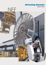
Service Instructions NFFIP 66<strong>Stromag</strong> <strong>Dessau</strong>safety in motionElectromagnetic Double Face Spring – Applied Brake 01.06.20094 Construction, functioning, construction characteristicsFig. 14.1 Designation of individual components(shown size NFF 16 with option speedometer installation)1 Coil body with coil 30 condensation heater2 friction lining assy. 40 screw for tacho flange3 terminal box assy. 41 brake mounting screw4 hand lever assy. 42 cylindric screw10 armature disc 46 mounting screw for hand release end cap11 brake flange 47 screw for locating dog12 tacho flange 49 emergency release screw13 outer body 50 cap screw for emergency release14 adjusting ring 52 screw for lockable hand release15 hub 60 seal ring for tacho20 shim 61 seal ring for brake flange21 compression spring 63 counter nut for micro switch22 locating doc 64 set screw (micro switch)23 terminal box spacer 65 cap screw for airgap measurement24 brass pin 67 gland25 hand release end cap 73 nameplate26 hand release pivot pin 74 metal tack (to mount identification plate)27 grooved ball bearing 76 adhesive28 micro switch 78 washer for pos. 5281 seal ring for pos. 507
Service Instructions NFFIP 66<strong>Stromag</strong> <strong>Dessau</strong>safety in motionElectromagnetic Double Face Spring – Applied Brake 01.06.20094.2 Functioning and design characteristics of the standard versionThe brake NFF is a spring-loaded electromagnetic double-face brake which brakes withoutcurrent and is released electromagnetically.The brake type NFF meets highest requirements with regard to fatigue strength and robustnessand is seawater-proof. The brakes are manufactured and tested in accordance with DIN VDE0580.The brake is screwed to a motor or any other machine part by means of cyl. screws (mountingscrews pos. 41).The coil body contains a coil which is potted with a synthetic resin compound in accordancewith thermical class 155 (F), (max. limit of temperature 155°C).If the coil is not excited, the springs (21) press the armature disc (10) against the friction disc(2), which is firmly clamped between the torsion-protected armature disc (10) and the brake disc(11) and thus prevented from rotating. The braking effect is transmitted from the geared frictiondisc (2) via the hub (15) and a fitting key to the shaft. If the coil is connected to a direct voltageas specified on the identification plate (73), the magnetic force will draw the armature disc (10)to the coil body (1) overcoming the spring pressure. The friction disc (2) is released, the brakingeffect is cancelled and the brake is released.4.3 Mechanical release by means of emergency release screwsFig. 21 coil body with coil11 brake flange13 outer body49 emergency release screw50 cap screw for axial emergency release81 seal ring8
Service Instructions NFFIP 66<strong>Stromag</strong> <strong>Dessau</strong>safety in motionElectromagnetic Double Face Spring – Applied Brake 01.06.2009For the mechanical release in case of emergency of the system use red marked screws (49)which have to be removed of its position (coil body (1) – outer body (13) – brake flange (11)) (upto size NFF 10 loosely attached) – up to size NFF 63-2 screws, up size NFF 100 –3 screws).For release, unscrew the cap screws (50) from the coil body (1). In the now free holes, screw inthe release screws (49). The release is made by alternating clockwise turning of the screws untilthe braking effect is cancelled.Caution!The emergency release is self-locking; for normal operation it must be re-turned into the initialposition, i.e. the screws (49) are re-turned counter-clockwise. Then re-screw the release screws(49) into the original threaded hole (coil body (1) – outer body (13) – brake flange (11)). Thenscrew the cap crews (50) into the coil body (1). We recommend to seal the threaded holes withhylomar.Take care that the seal rings (81) are also re-fitted. This is necessary to assure the full electricaloperation and sealing effect (IP 66).Manual emergency release shall not be used to maintain temporary operation!4.4 Mechanical release by means of hand lever (optional)By pulling the hand lever (4) at approx. 30° towards the back of the brake the armature disc (10)is moved axially until it is lying against the coil body (1) thus the friction disc lining (2) may rotatefreely.Manual emergency release shall not be used to maintain temporary operation!4.5 Current supplies and electrical connectionsMake sure that the electrical connection is performed by expert personnel taking into accountthe installation regulations (such as DIN IEC 92).The coil has been designed for 100% duty factor and connection to D.C. supply only, given onthe identification plate (residual ripple< 0.5).According to DIN VDE 0580 the permanently admissible voltage change is +5% to –10% of thenominal voltage.To protect the coil or the power supply unit it is recommended to connect a varistor of thecorresponding operating A.C. voltage range and with the required power to the rectifier output.5 Assembly and dismantling(individual parts with Item-No. see chap. 4.1)Caution! The brake must only be operated, maintained and repaired by accordinglyauthorized, trained and instructed people. Each such person must have read andunderstood the complete instruction manual and must have been informed in particularabout possible risks and danger.9
Service Instructions NFFIP 66<strong>Stromag</strong> <strong>Dessau</strong>safety in motionElectromagnetic Double Face Spring – Applied Brake 01.06.20095.1 AssemblyThe assembly to the motor is simple, no dismantling of the brake is required.- Check the connecting dimensions for compatibility with the brake.- Remove any existing transportation or bearing protections devices, as well as any burror impact damage.- Check face run out of the flange mounting surface relative to the shaft to be braked(tolerance class N in accordance with DIN 42955 should not be exceeded).- Slightly grease shaft and fitting key with assembly paste. Mount pinion (15) and secure itaxially.- Use suitable slings (shackles or equivalent) to move the brake cautiously across thepinion (15) and turn the shaft or swivel the brake to engage pinion teeth with the matingteeth of the friction disc (2). (The friction disc is pre-centered during the final acceptanceof the brake).Caution!Do not use force! Do not tilt! Pay attention of the cable!- offer brake onto the motor in the position specified- tighten the mounting screws (41) to correct bolt tightening torque (as specified on thedrawing)- To prevent mechanical blocking of the stainless steel screws (41) we recommend togrease these screws with Klüber paste HEL 46-54- Make sure that the electrical connection is performed by expert personnel taking intoaccount the installation regulations (such as DIN IEC 92).Caution!When mounting always assure that all seal rings and sealings are properly lying in theaccordingly provided positions (IP 66).5.2 Mounting accuracyThe concentric run of the shaft piece on which the driving hub (15) is fixed as well as thecoaxiality and the run - out of the fixing flange must comply with tolerance class "N" of DIN42955.5.3 Dimensions, space requirement and massThe binding dimensions, the mass (weight) and the other technical data are stated on thedimensional drawing which is binding for the pertinent order. This drawing can be inquired atour after - sales service; address is given in chap. 10.3.5.4 DismantlingDismantling is subject to the same instructions and regulations as installation. Carry out theoperations in inversed order of succession!Important note!Check up: The brake must be torque-free on the output side.Before removing the brake, disconnect it from the mains and secure with slings.10
Service Instructions NFFIP 66<strong>Stromag</strong> <strong>Dessau</strong>safety in motionElectromagnetic Double Face Spring – Applied Brake 01.06.20096 Initial setting into service(Single parts with item designation as per chap. 4.1)Before the initial setting into service, the following test measures are necessary:• As the new friction lining does not yet dispose of optimum friction characteristics, someelectric releases have to be carried - out to smooth the friction face pinpoints.• The electric connection values on the nameplate (73), see chap. 1.1, must comply with thevalues at site• The brake must be undamaged, i.e. it must not have any damage generated duringtransportation, stocking, etc.• The prescribed service conditions (chap. 7.1) must comply with those ones at site• Not only the emergency manual release as per chap. 4.3 but also the hand lever emergencyrelease as per chap. 4.4 or 9.3 must not be active.7 OperationNotwithstanding any instructions given below, operation of the brake mustalways comply with local mandatory safety and accident prevention rules. Compliance withthese rules shall be ensured by the user.7.1 Operating conditionsThe operating conditions to be maintained for a faultless operation of the brake are given below:- The operating temperature should not be below –30°C and not above +50°C.- In the case of higher and/or lower ambient temperatures, please contact our after-salesservice (for address see Chapter 10.3).- Air humidity may be 100%.11
Service Instructions NFFIP 66<strong>Stromag</strong> <strong>Dessau</strong>safety in motionElectromagnetic Double Face Spring – Applied Brake 01.06.20097.2 Protection classesFig. 3In completely mounted condition and under consideration of the following hintsassembled, the brake as standard execution (as shown in fig 3) complies withprotection class IP 66, in accordance with DIN 40050 and DIN VDE 0530.When using original <strong>Stromag</strong> accessory, such as terminal box, cable glands (see Fig. 1)the type of protection is maintained. The same applies when the speed encoder is rigidlyconnected to the cover by means of a flange gland which is sealed by round ring.Sealings of through-shafts (by means of shaft seal ring), reduce the type of protection inrelation to the execution. Please consult the manufacturer.Important note!The contact surfaces of the brake to the motor, as well as the surfaces of the"speedometer connection" option shall be sealed with suitable means (e.g. Hylomar orsealing ring) to guarantee the protection class.The user has to provide a sealing element on the shaft in direction to the motor side inorder to prevent the penetration of grease from the motor bearing.12
Service Instructions NFFIP 66<strong>Stromag</strong> <strong>Dessau</strong>safety in motionElectromagnetic Double Face Spring – Applied Brake 01.06.20097.3 Duty cycle, switching frequencyThe design as well as admissible loads on brakes as per braking torque, speed,switching capacity are given under „Technical Data“ (see Chapter 1) and thedimensional drawing (appendix). If any of these data are exceeded consult themanufacturer.7.4 Trouble shooting (individual parts with Item-No. see chapter 4)Störungen Mögliche Ursachen Erforderliche MaßnahmenInsufficient brakingeffectFriction surfaces are not free fromgreaseMax. Air gap “off” exceeded due towear of friction liningreplace friction disc (2)re-adjust brake (chapter 8.3.), ifnecessary replace friction disc (2)Brake not completely run-inBrake has been overloadedSpring ruptureLet brake run inReplace brakeDismantling of brakemanufacturercontactNo braking effectBrake does not releasewhen micro switch isused:No operational switchindicationManual release (4) has beenactuated and not re-setMax. Air gap „off“ too large due towear of friction liningFriction disc (2) is stuck on pinion(15)Armature disc (10) distortedCoil connecting voltage too lowCoil defectiveFeed line defectiveContact points looseforeign particles in the air gap (e.g.spring rupture)Armature plate is not beingattracted against the coil bodybecause of:- max. air gap has been exceeded- foreign particles in the air gapSee Chapter 4.3Re-adjust brake (chapter 8.3.) ifnecessary replace friction disc (2)Replace friction disc (2) and pinion (15)(chapter 8.4.)Replace brake (chapter 5)Check DC voltage supplyReplace brake (chapter 5)Renew feed lineRe-tighten contact pointsDismantling of brake, contactmanufacturerRe-adjust brake (chapter 8.3.) ifnecessary replace friction disc (2)Check position of micro switch underconsideration of adjustment procedure ofmicro switchDismantle and clean the brake13
Service Instructions NFFIP 66<strong>Stromag</strong> <strong>Dessau</strong>safety in motionElectromagnetic Double Face Spring – Applied Brake 01.06.2009- Remove the mounting screws (41) and (42)- dismantle the complete coil body assembly with outer body (13) from the brake flange (11)taking care not to damage armature disc (10)- remove shim (20) and re-assemble in inversed order coil body assembly and outer body.- offer brake onto the motor in the position specified- tighten the mounting screws (41) to correct bolt tightening torque (as specified on thedrawing)To simplify maintenance works the armature disc (10) may be retained in position by using theemergency release screws (49). Ensure these are removed before setting into operation.Note: If the shim (29) has previously been removed, a new friction disc (2), see chap. 8.4.,together with shim (20) has to be fitted.Attention: On assembling the brake or replacing the friction disc, care should be taken that thelinings do not come in contact with grease etc. Greasy substances if any, can be removed bysuitable degreasing agents. Never use petrol or paraffin.8.4 Replacement of the friction discProceed as follows:Important ! Check up: The brake must be torque-free on the output side.- Remove the mounting screws (41) and (42)- dismantle the complete coil body assembly with outer body (13) from the brake flange (11)taking care not to damage armature disc (10)- take the friction disc (2) from the pinion (15)- clean the brake- push the friction disc (2) onto the toothing of the pinion (15)- fit the shim (20)- mount in inversed order coil body assembly (1) and outer body (13)- offer brake onto the motor in the position specified- tighten the mounting screws (41) to correct bolt tightening torque (as specified on thedrawing)To simplify maintenance works the armature disc (10) may be retained in position by using theemergency release screws (49). Ensure these are removed before setting into operation.The new friction linings on the friction disc will transmit the full braking torque onlyafter a certain run-in period.15
Service Instructions NFFIP 66<strong>Stromag</strong> <strong>Dessau</strong>safety in motionElectromagnetic Double Face Spring – Applied Brake 01.06.20099 Variants (optional)Condensation heaterMicro switch tomonitor switching statesMicro switch forwear monitoringWithout terminal box;1m flying lead64XPG 1198Electrical connectionvia terminal blockwithin terminal boxOptions:rectifier, quickswitching unitMKL6 x 60° = 360°60°JØ 100Ø 85 G76 x M6, 8 mm thread lengthadjustablebrake torqueBrake handlesupportEnd cover with tachoprovision; bore Ø85 G7QEmergency handrelease leverFig. 4Brake Size 2 4 6.3 10 16 25 40 63 100 160 250 400 630 1000M 115.5 128.5 128 125 151 165 179 196 238 260 290 327 364 420K 179.5 198 201 216 251 276 300 343 408J 20.9 28 29 29 32 39 40 45 54 Refer to <strong>Stromag</strong> <strong>Dessau</strong>L 95 110 110 123 140 150 170 200 220X 19 33.75 33.75 38 48 62 83 86 113 125.5 133.5 168 172 182Q 110 110 110 110 110 150 150 250 50016
Service Instructions NFFIP 66<strong>Stromag</strong> <strong>Dessau</strong>safety in motionElectromagnetic Double Face Spring – Applied Brake 01.06.20099.1 Execution with micro switchIf the switching condition of the brake should be controlled, a micro switch (28) could be used.When the armature disc (10) is moved against the coil body (1) as a result of theelectromagnetic force of the coil or the actuation of the mechanical emergency release device,(chap. 4.3), it will operate a micro switch (28) via set screw (64). The micro switch (28) may beincluded in the control circuit of the motor contactor as a normally open or normally closedcontact.The micro switch is preset in our works and should not require adjustment. Ifreplacement of the micro switch is required this must be done by our agreed procedure(096-701:181)9.2 Execution with adjusting ring to reduce the brake torqueThe torques given in the technical data(chap. 1.1.) were obtained only by fully tighteningthe adjusting ring (14). By turning the adjusting ring(14) this changes the pre-load of the cylindricalpressure springs (21) and the brake torque isaltered accordingly.The table shown here below indicates thedimension X and the respective torque rating.These are approx. figures onlyFig. 5Brakesize100%X(mm)90%X(mm)80%X(mm)70%X(mm)60%X(mm)50%X(mm)40%X(mm)30%X(mm)20%X(mm)10%X(mm)2 0 0.7 1.4 2.1 2.8 3.5 4.2 4.9 5.6 6.34 0 1.1 2.2 3.3 4.4 5.5 6.6 7.7 8.8 9.96.3 0 0.95 1.9 2.85 3.8 4.75 5.7 6.65 7.6 8.5510 0 1.3 2.6 3.9 5.2 6.5 7.8 9.1 10.4 11.716 0 1.3 2.6 3.9 5.2 6.5 7.8 9.1 10.4 11.725 0 0.7 1.4 2.1 2.8 3.5 4.2 4.9 5.6 6.340 0 0.55 1.1 1.65 2.2 2.75 3.3 3.85 4.4 4.9563 0 2.2 4.4 6.6 8.8 11.0 13.2 15.4 17.6 19.8100 0 1.03 2.06 3.09 4.12 5.15 6.18 7.21 8.24 9.27160 0 1.05 2.10 3.15 4.20 5.25 6.3 7.35 8.4 9.4517
Service Instructions NFFIP 66<strong>Stromag</strong> <strong>Dessau</strong>safety in motionElectromagnetic Double Face Spring – Applied Brake 01.06.20099.3 Hand lever emergency with self lockingOptionally the brake can be equipped with a self -locking hand lever release allowing the manualrelease in case of emergency, e.g. current failure.By pulling the hand lever (4) at approx. 30°towards the back of the brake the armature disc(10) is moved axially until it is lying against the coilbody (1) thus the friction disc lining may rotatefreely. The handle (4) must be screwed in at thisposition to operate the locking mechanism. Pleaseensure brake is fully released. Then screwed out torelease.Please note: the cap screws (50) can be removedand the emergency release screws can be fitted(see chapt. 4.3) to release brake (this isrecommended method of brake release).Fig. 6Manual emergency release shall not be used to maintain temporary operation!Please note: this is a Fail Safe Brake and “fails to safety” when there is a power failure.When locking handles are used this disables the Fail Safe system and we do notrecommend using them.9.4 Execution with condensation heaterIf strong temperature fluctuations are expected, a condensation heater (30) may be used toprevent the generation of condensation water. A special feed line will be provided accordingly.In case of questions please contact the manufacturer.9.5 Speedometer installationIf a speedometer connection is required for the brake, the brake is provided with a tacho flange(12) with connecting bores in accordance with „Euro dimensions“ (Diameter 85/100).It is recommended to connect the tachometer or the encoder to the shaft through a plug-typecoupling.Caution!The type of protection only maintains when the speed encoder is rigidly connected to the coverby means of a flange gland which is sealed by round ring.18
Service Instructions NFFIP 66<strong>Stromag</strong> <strong>Dessau</strong>safety in motionElectromagnetic Double Face Spring – Applied Brake 01.06.200910 Spare parts stocking, after-sales service10.1 Spare parts stockingStocking of spare and parts subject to wear is an important precondition for permanent andreliable functioning of the brake.Friction disc (2), armature disc (10), brake flange (11) and pinion (15) (for item see Chapter 4.1)are parts subject to wear.Warranty will be provided only for the original spare parts supplied by us. We expressly statethat the installation or use of spare parts other than the original ones supplied by us willnegatively affect the design characteristics of the brake and thus have an impact on activeand/or passive safety.<strong>Stromag</strong> <strong>Dessau</strong> GmbH shall have no warranty obligations for any damage caused by the useof spare parts or accessories other than the original ones supplied by us.Please bear in mind that often particular manufacturing and delivery specifications exist forparts manufactured by us or bought from others, and that we offer spare parts to the up-datedtechnical conditions and the up-dated legal prescriptions.10.2 Data for spare parts ordersPlease specify the following details when ordering spare parts:- Series and size of brake- article code- Location and designation of spare part (see chapt. 4.1. and fig. 1)- Number of pieces10.3 Address of after-sales serviceThis is our address for after-sales service and spare parts distribution:<strong>Stromag</strong> <strong>Dessau</strong> GmbH<strong>Dessau</strong>er Str. 10D-06844 <strong>Dessau</strong>-RoßlauTelefon : +49 (340) 2190-203Telefax : +49 (340) 2190-201E-Mail : vertrieb.dessau@stromag.comInternet : http://www.stromag-dessau.deIf you require a service engineer, please contact our "Technical after-sales service" under theabove address.19
Service Instructions NFFIP 66<strong>Stromag</strong> <strong>Dessau</strong>safety in motionElectromagnetic Double Face Spring – Applied Brake 01.06.200911 Listed standards and regulationsDIN 6885DIN 40050DIN 42948DIN 42955DIN IEC 92DIN VDE 0530DIN VDE 0580VDE 0660 T 200/09.82,89/336/EEC (EMC)93/68/EECSheet 1 Fitting keys(VDE 0470) Protection classesFastening flanges for electrical machinesConcentricity of shaft ends, co-axial and true running offastening flanges of rotating electrical machinesElectrical equipment on shipsRotating electrical machinesRegulations for electrical devicesSection 4.2.4, Table 1 - Inductive loadElectromagnetic compatibilityLow Voltage Directive20
NFF – Service Instruction <strong>Stromag</strong> <strong>Dessau</strong>safety in motionair gapBrake size 2 4 6.3 10 16 25 40 63 100 160 250 400 630 1000Brake torque Nm 20 40 63 100 160 250 400 630 1000 1600 2500 4000 6300 10000Nom. speed min -1 5300 4900 4500 4100 3800 3500 3200 3000 2800 2200 1900 1600 1400 1200Moment of InertiaB sidekgm 2 0.0004 0.00043 0.00080 0.00125 0.00340 0.00430 0.01212 0.01463 0.04171 0.14821 0.23515 0.43412 1.0161 1.5610Weight kg 6.3 10.4 13 14 21 30 40 68 85,5 133 167 278 367 491Nom. voltage V DC 103 103 103 103 103 103 103 103 103 103 207 207 207 207Nom. power W 89,9 90,7 113,9 110,4 115,8 136,6 212,9 227,3 277,6 353,5 367 400,9 489,6 535,5Nom. current A 0,87 0,88 1,11 1,07 1,12 1,37 2,07 2,21 2,70 3,43 357 3,89 4,75 5,2Air gap norm. mm 0.6 0.6 0.6 0.6 0.6 0.6 0.6 0.6 0.6 0.6 0.6 0.6 0.6 0.6Air gap max. mm 1 1 1.2 1.2 1.2 1.2 1.3 1.5 1.6 1.6 1.8 1.8 1.6 1.6a mm 150 165 175 190 225 250 270 314 350 440 500 560 650 750b mm 135 152 162 175 205 225 250 292 325 418 472 530 620 710c H8 mm 120 140 140 160 180 200 220 240 270 340 390 460 530 600d max H7 mm 25 30 40 40 45 50 60 60 80 110 120 130 140 160e mm 53 55 55 65 76 78.5 90 96 100 200 215 240 270 300f mm 47 80 80 65 80 90 105 120 158 220 255 280 320 330g mm 19 33,7 33,75 38 48 62 83 86 113 125,5 133,5 168 172 182h mm 30 33 31 26 29 30 32 32 32 33 33 33 33 33i mm 73.5 89.6 92.8 95.3 104 121 141 145 168 182.6 191 226 225 265j mm 20,9 28 29 29 32 39 40 45 54 On request6 screws k mm M5 M6 M6 M6 M8 M8 M8 M10 M10 M12 M16 M16 M16 M20l mm 95 110 110 123 140 150 170 200 220 On requestm mm 10.5 7.8 13 14 14 13 14.2 19.5 19 24.4 21.4 26.3 30 30n mm 2.5 2.5 2.5 3.5 3.5 3.5 4 4 5 5.5 5 5 6 6p mm 24 28 30 30 35 45 45 55 75 125 130 150 185 210q mm 110 110 110 110 110 150 150 250 500 On requestr mm 115,5 128,5 128 125 151 165 179 196 238 260 290 327 364 420s mm 8.5 10.5 10 10 10 10 10 12 10 10 10 10 10 10t mm 123 140 150 146 168 172 184 230 255 270 280 320 340 380u mm 179,5 198 201 216 251 276 300 343 408 On request