STEELDOC Code of Practice for Structural Steelwork Documentation
STEELDOC Code of Practice for Structural Steelwork Documentation
STEELDOC Code of Practice for Structural Steelwork Documentation

You also want an ePaper? Increase the reach of your titles
YUMPU automatically turns print PDFs into web optimized ePapers that Google loves.
2SCNZ –12: 2006
SCNZ –12: 2006Published by:Steel Construction New Zealand Inc.17-19 Gladding PlacePO Box 76403Manukau CityManukau 2241New ZealandPhone: +64 9 2635 635Fax: +64 9 2622 856Copyright © Steel Construction New Zealand Inc. 2006No portion <strong>of</strong> this report may be copied or reproduced in any <strong>for</strong>m or by any meanswithout the written permission <strong>of</strong> the Steel Construction New Zealand Inc.November 2006ISSN 1177-3855Steel Construction New Zealand Inc.(SCNZ) is a member based, not-<strong>for</strong>-pr<strong>of</strong>it societyincorporated under the Incorporated Societies Act 1908.Steel Construction New Zealand Inc.(SCNZ) has three basic objectives:-To promote awareness <strong>of</strong> the advantages <strong>of</strong> steel construction-To promote excellence in the delivery <strong>of</strong> steel construction solutions-To encourage training and career development within the steel construction sectorDisclaimerConsiderable ef<strong>for</strong>t has been made and reasonable care taken to ensure the accuracyand reliability <strong>of</strong> the material contained within this report. However SCNZ and the authors<strong>of</strong> this report make no warranty, guarantee or representation in connection with this reportand shall not be held liable or responsible <strong>for</strong> any loss or damage resulting from the use<strong>of</strong> this report.3
4SCNZ –12: 2006
SCNZ –12: 2006Table <strong>of</strong> Contents1 PREFACE....................................................................................................................... 92 INTRODUCTION.......................................................................................................... 113 DEFINITIONS OF TERMS ........................................................................................... 133.1 GENERAL.......................................................................................................................... 133.2 PERSONS TO THE CONTRACT ..................................................................................... 133.2.1 PRINCIPAL .................................................................................................................................... 133.2.2 PRINCIPAL’S REPRESENTATIVE.............................................................................................. 133.2.3 CONTRACTOR ............................................................................................................................. 133.2.4 SUBCONTRACTOR...................................................................................................................... 133.3 OTHER TERMS................................................................................................................. 143.3.1 CONTRACT AGREEMENT .......................................................................................................... 143.3.2 CONTRACT DOCUMENTS.......................................................................................................... 143.3.3 CONTRACT WORKS.................................................................................................................... 143.3.4 GENERAL CONDITIONS ............................................................................................................. 143.3.5 DRAWINGS ................................................................................................................................... 143.3.6 FOB ITEMS .................................................................................................................................... 143.3.7 “FOR CONSTRUCTION” .............................................................................................................. 143.3.8 PERSON ........................................................................................................................................ 153.3.9 PRIMARY STRUCTURE............................................................................................................... 153.3.10 SHOP DRAWINGS ................................................................................................................... 153.3.11 SHOP DRAWING INSPECTION OR REVIEW ....................................................................... 153.3.12 SPECIAL CONDITIONS ........................................................................................................... 153.3.13 SPECIFICATIONS .................................................................................................................... 153.3.14 TENDER DOCUMENTS........................................................................................................... 153.3.15 VARIATION................................................................................................................................ 154 CONTRACTUAL RELATIONSHIPS AND COMMUNICATION..................................... 174.1 PRINCIPAL RESPONSIBLE FOR DESIGN..................................................................... 174.2 CONTRACTOR RESPONSIBLE FOR DESIGN.............................................................. 185 STEEL CONSTRUCTION COMPLEXITY CATEGORIES ............................................. 195.1 LOW RISE RESIDENTIAL HOUSING.............................................................................. 195.2 FOUNDATION STRUCTURES ........................................................................................ 195.3 MULTI-LEVEL STRUCTURES......................................................................................... 195.4 SINGLE LEVEL & ROOF STRUCTURES........................................................................ 195.5 CANOPIES, CLADDING AND FEATURE STRUCTURES ............................................. 195.6 INDUSTRIAL SUPPORT STRUCTURES........................................................................ 196 CONTRACT DOCUMENTATION RESPONSIBILITIES................................................ 206.1 RESPONSIBILITIES OF THE PRINCIPAL’S REPRESENTATIVE ................................ 206.2 IDENTIFICATION OF DOCUMENTS............................................................................... 206.3 SUFFICIENCY OF DOCUMENTS.................................................................................... 206.4 LIMITATIONS OF TENDER DOCUMENTS..................................................................... 206.5 DIMENSIONS.................................................................................................................... 216.6 CO-ORDINATION OF DOCUMENTS .............................................................................. 226.7 “FOR CONSTRUCTION” AUTHORISATION................................................................... 226.8 DEVELOPMENT OF SHOP DRAWINGS ........................................................................ 226.8.1 FOR CONSTRUCTION: MATERIAL ORDER.......................................................................................... 226.8.2 FOR CONSTRUCTION: CONNECTIONS ............................................................................................... 236.8.3 FOR CONSTRUCTION: SERVICES ...................................................................................................... 236.9 DESIGN RESPONSIBILITY.............................................................................................. 245
SCNZ –12: 20066.10 RESPONSIBILITY FOR DIMENSIONS............................................................................ 246.11 SHOP DRAWING INSPECTION / REVIEW..................................................................... 247 STEELWORK CONTRACT DOCUMENTATION: GENERAL REQUIREMENTS........... 277.1 ALL STRUCTURAL STEELWORK DRAWINGS IDENTIFIED ........................................ 277.2 PRINTED AT SCALE DRAWN ......................................................................................... 277.3 CAD AND 3D MODELLING FILES..................................................................................... 277.4 COORDINATION WITH MECHANICAL, ELECTRICAL & ARCHITECTURAL.............. 277.5 SPECIFICATIONS............................................................................................................. 277.6 STANDARD STEELWORK NOTES................................................................................. 277.7 DIMENSIONS.................................................................................................................... 287.8 MATERIALS ...................................................................................................................... 287.9 BRACING FRAME AND MEMBER SEISMIC CATEGORY ............................................ 287.10 MEMBER ORIENTATION................................................................................................. 287.11 PRE-CAMBER................................................................................................................... 287.12 SHEAR STUDS ................................................................................................................. 287.13 SPLICE LOCATIONS........................................................................................................ 287.14 BASEPLATES AND CAST-IN PLATES / ITEMS ............................................................. 287.15 PASSIVE FIRE PROTECTION......................................................................................... 297.16 PROTECTIVE COATINGS ............................................................................................... 297.17 SPECIAL ERECTION REQUIREMENTS......................................................................... 297.18 FOUNDATION PLAN ........................................................................................................ 297.19 TYPICAL FLOOR PLAN.................................................................................................... 297.20 ROOF PLAN ...................................................................................................................... 297.21 ELEVATIONS .................................................................................................................... 307.22 CONNECTIONS................................................................................................................ 308 PRELIMINARY STEELWORK DOCUMENTATION: GENERAL REQUIREMENTS ...... 338.1 GENERAL.......................................................................................................................... 338.2 SCOPE OF PRELIMINARY STRUCTURAL STEELWORK DOCUMENTS IDENTIFIED338.3 SPECIFICATION CLAUSES ON DRAWINGS................................................................. 338.4 DIMENSIONS.................................................................................................................... 338.5 MATERIALS REQUIRED.................................................................................................. 338.6 MATERIALS & WELD TESTING ...................................................................................... 338.7 BRACING FRAME SEISMIC CATEGORY ...................................................................... 338.8 PRE-CAMBER................................................................................................................... 348.9 SHEAR STUDS ................................................................................................................. 348.10 CONNECTIONS & BASEPLATES ................................................................................... 348.10.1 FIXING SYSTEM : .......................................................................................................................... 348.10.2 DESIGN ACTION TYPE : ................................................................................................................ 348.11 SPLICE LOCATIONS........................................................................................................ 348.12 EMBEDDED ITEMS AND EDGE TRIMMERS................................................................. 358.13 MECHANICAL , ELECTRICAL PENETRATIONS & ARCHITECTURAL FIXINGS........ 358.14 PASSIVE FIRE PROTECTION......................................................................................... 358.15 PROTECTIVE COATINGS ............................................................................................... 358.16 SPECIAL ERECTION REQUIREMENTS......................................................................... 358.17 TEMPORARY BRACING REQUIREMENTS................................................................... 359 DOCUMENTATION CONTACTS LIST......................................................................... 3710 DOCUMENTATION RESPONSIBILITY CHECKLIST............................................... 3911 STRUCTURAL STEELWORK DRAWINGS LIST ...................................................... 4512 DOCUMENTATION COMPLETION CHECKLISTS................................................... 476
SCNZ –12: 200613 <strong>STEELDOC</strong> DOCUMENTATION CHECKLIST SOFTWARE ..................................... 5713.1 INTRODUCTION .................................................................................................................... 5713.2 INSTALLATION...................................................................................................................... 5713.3 INPUT AND OUTPUT PROCEDURES ...................................................................................... 5713.3.1 STEP 1: INITIAL SETUP – DESIGN CONSULTANTS CONTACT DETAILS SELECTION ......................... 5713.3.2 STEP 2: INITIAL SETUP – CONTRACT DRAWING LIST SELECTION ERROR! BOOKMARK NOT DEFINED.13.3.3 STEP 3: INITIAL SETUP – DESIGN CONSULTANT TASK CHECKLIST SELECTION.............................. 6013.3.4 STEP 4: CHECK LISTS SELECTION .............................................................................................. 6114 CONCLUSION.......................................................................................................... 6515 REFERENCES .......................................................................................................... 677
SCNZ –12: 20061 PrefaceThe use <strong>of</strong> structural steelwork in construction in New Zealand is rapidly increasing. Successfulsteel construction is an exercise in teamwork. Effective and clear communication is thefoundation <strong>of</strong> confidence and achievement. In steel construction the Contract Drawings and theSpecifications are the primary medium <strong>of</strong> project communication. There<strong>for</strong>e the quality <strong>of</strong> theirdefinition, clarity <strong>of</strong> their presentation and the conciseness <strong>of</strong> their content will largely determinethe economic and technical success <strong>of</strong> the steel construction project.The purpose <strong>of</strong> Steeldoc: <strong>Code</strong> <strong>of</strong> <strong>Practice</strong> <strong>for</strong> <strong>Structural</strong> <strong>Steelwork</strong> <strong>Documentation</strong> is there<strong>for</strong>e toclearly identify what Contract Documents, in particular the Drawings, should contain to get goodvalue out <strong>of</strong> steel construction in New Zealand. As with any <strong>Code</strong> <strong>of</strong> <strong>Practice</strong>, the aim is to setminimum per<strong>for</strong>mance criteria, that are readily achievable and reflect common practice in theindustry. The hope is that practitioners will quickly exceed these criteria and set their own levels<strong>of</strong> best practice <strong>for</strong> others to aspire to.This second edition <strong>of</strong> the <strong>Code</strong> <strong>of</strong> <strong>Practice</strong> is reissued as report SCNZ 12:2006 followingincorporation <strong>of</strong> Steel Construction New Zealand. This second edition includes the s<strong>of</strong>twareprogramme SteelDoc. The original <strong>Code</strong> <strong>of</strong> <strong>Practice</strong> featured various checklists in hardcopy<strong>for</strong>mat. SteelDoc has been developed to streamline drawing <strong>of</strong>fice documentation Quality Controlby presenting these checklists in an easy to use <strong>for</strong>mat.General requirements and checklists are given <strong>for</strong> the Drawings and Specification content thatcan be used by the Principal’s Representative as part <strong>of</strong> the contract documentation and qualityassurance system. Typical documentation responsibilities and practice <strong>of</strong> the Principal’sRepresentative under three commonly used General Conditions <strong>of</strong> Contract are set out. Theseare the Conditions <strong>of</strong> Contract <strong>for</strong> Building and Civil Engineering Construction, NZS3910:1998;New Zealand Institute <strong>of</strong> Architects Standard Conditions <strong>of</strong> Contract, SCC1:2000 and NationalBuilding Contract (General), NBC-G1: 1998.All <strong>of</strong> the above are used in the common building contract arrangement in which the Principalsupplies the design <strong>of</strong> the Contract Works in the <strong>for</strong>m <strong>of</strong> unambiguous Contract Documents <strong>of</strong>sufficient clarity and definition, that the Contract Works may be fairly measured, valued andconstructed. Design responsibility rests with the Principal. The Contract Drawings andSpecifications are incorporated directly into subcontract agreements with subcontractors.Subcontract documentation responsibilities under design-build general conditions <strong>of</strong> contract,such as the FIDIC Conditions <strong>of</strong> Contract <strong>for</strong> Plant and Design-Build, 1999, are not covereddirectly by this document. However this <strong>Code</strong> <strong>of</strong> <strong>Practice</strong> <strong>for</strong> <strong>Structural</strong> <strong>Steelwork</strong> <strong>Documentation</strong>,while not directly written in the terminology <strong>of</strong> design-build contracts, may be made sufficientlyin<strong>for</strong>mative by substituting the term, Principal’s Representative, with the term, Contractor’sRepresentative. In the design-build contract the Contractor supplies the design <strong>of</strong> the SubcontractWorks in the <strong>for</strong>m <strong>of</strong> unambiguous Subcontract Documents <strong>of</strong> sufficient clarity and definition, thatthe Subcontract Works may be fairly measured, valued and constructed.The role <strong>of</strong> the Principal’s Representative in the documentation process <strong>for</strong> design-build contractsis different to that in the above contract. The responsibility <strong>for</strong> the design and the adequacy <strong>of</strong> theSubcontract Documents <strong>for</strong> the Contract Works lies largely with the Contractor. The contractualrelationship between the Contractor, the Contractor’s Representative and the Subcontractors isalso different. While the Contractor may take on design responsibility its Subcontractors, in manyinstances, will not be required to. The Subcontractor’s contractual relationship with the designbuildContractor may there<strong>for</strong>e not be much different from that <strong>of</strong> the Contractor with the Principalin the more traditional construction contract in which the Principal takes design responsibility.9
SCNZ –12: 2006The recommendations and checklists contained in the <strong>Code</strong> <strong>of</strong> <strong>Practice</strong> <strong>for</strong> <strong>Structural</strong> <strong>Steelwork</strong><strong>Documentation</strong>, have been put together as the result <strong>of</strong> wide consultation with and feedback fromNew Zealand steel fabricators, and detailers in particular. Valuable input from consultingengineers and construction companies has also been appreciated. Steel Construction Industry-New Zealand, (SCI-NZ), representing many companies involved in steel construction, and HERAhave made the writing <strong>of</strong> this document possible through funding and support <strong>of</strong> the SteelStructures Analysis Service. The function <strong>of</strong> the Steel Structures Analysis Service has now beentaken over by Steel Construction New Zealand which was <strong>for</strong>merly known as Steel ConstructionIndustry New Zealand.Steel construction is fundamentally about turning the dreams and visions <strong>of</strong> others into reality.The Contract Drawings and Specifications in particular are the written expression <strong>of</strong> those dreamsand visions. By encouraging the improvement <strong>of</strong> Contract <strong>Documentation</strong> we believe that theconfidence, necessary to allow those dreams to grow and to be run with by New Zealand’s steelconstruction industry, will be fostered.Getting the dream to reality has always required clarity in documentation: In the words <strong>of</strong>Habbakuk, “Record the vision and inscribe it on tablets, that the one who reads it may run!”In this amendment to SCNZ 12, the companion s<strong>of</strong>tware (SteelDoc 1.0b) has been revised tomake data entry easier.Clark HylandBE(Civil) BCom CPEngSecretary ManagerSteel Construction New Zealand10
SCNZ –12: 20062 IntroductionFabricated structural steelwork is a value added product. It requires skilled design, management,labour and machine time to be added to the raw material <strong>of</strong> steel plate and sections, to produce ahighly versatile, customised building product. A small number <strong>of</strong> generic connection types areused <strong>for</strong> the vast majority <strong>of</strong> steelwork fabrication. By using pre-specified industry normalconnections, the structural engineer can minimise design time and optimise fabrication cost.Design expertise can be devoted to solving the non-standard connection configurations. TheContractor can develop efficient practices <strong>for</strong> manufacturing connections based on industrynorms.The last two decades have seen the rise <strong>of</strong> new and varying <strong>for</strong>ms <strong>of</strong> construction contractagreements and design and construction arrangements. The aim <strong>of</strong> such change may have beento improve the delivery <strong>of</strong> construction solutions. However, unless well managed andcommunicated, change simply results in loss <strong>of</strong> confidence and confusion.Clarity <strong>of</strong> communication and responsibility fosters confidence and success. Clarity, consistencyand completeness <strong>of</strong> documentation are the key issues <strong>for</strong> design consultants to focus on inpreparing drawings and specifications that will <strong>for</strong>m the backbone <strong>of</strong> the Contract Documents. Itis a fact the architectural and engineering design consultants with reputations <strong>for</strong> excellence indesign documentation attract better tender prices to projects <strong>for</strong> their clients.The Contract Documents are the only <strong>for</strong>mal basis <strong>of</strong> what happens on a construction project.They are the primary method <strong>of</strong> communication <strong>of</strong> construction per<strong>for</strong>mance requirements.Where Contract Documents are difficult and time consuming to interpret due to being incomplete,ambiguous or poorly presented, additional cost, re-work and delay is added to the project.There is a quantifiable amount <strong>of</strong> detail and work required between conceptual design and thecompletion <strong>of</strong> shop drawings involving architects, engineers, project managers, the fabricator andthe shop detailer. It is in everyone’s interest that tasks and responsibilities in the documentationprocess are clearly defined early in the project. Where possible these should follow commonlyheld conventions so as to minimise confusion and maximise efficiency. Oversights will occureven with the best intentions and ef<strong>for</strong>ts, however good documentation practice will minimise thenumber and their effects on the Contract Works.Presentation styles and extent <strong>of</strong> contract documentation varies from consultant to consultant andaround the country. It also varies with the size and complexity <strong>of</strong> the project. There is nouniversally recognised right or wrong style or layout <strong>of</strong> drawings. However there is a minimumamount <strong>of</strong> in<strong>for</strong>mation that must be present on the Drawings and in the Specification <strong>for</strong> theContract to run smoothly.• Clear, complete and unambiguous Contract Documents encourage:• Achievement <strong>of</strong> construction programmes.• Minimisation <strong>of</strong> errors and omissions.• More knowledgeable and competitive bids.• Avoidance <strong>of</strong> duplication <strong>of</strong> ef<strong>for</strong>t.• Lower material supply costs.• Clearly defined responsibilities.• Minimisation <strong>of</strong> field errors.• Reduction in revision costs and delays.• Elimination <strong>of</strong> costly start-ups, Requests For In<strong>for</strong>mation (RFI’s), clarification and verification.• Reduction in demobilisation and remobilization.• Increased morale among suppliers.Steel construction requires good up front planning as most <strong>of</strong> the steelwork is prefabricatedquickly <strong>of</strong>f-site.11
SCNZ –12: 2006The issue <strong>of</strong> increasingly incomplete design documentation is not just one that occurs in the NewZealand construction industry. The following are a few quotes from New Zealand and overseas:“Due to …design pr<strong>of</strong>essionals not having enough time to complete preparation <strong>of</strong> contractdocuments the contractor bidding process, including steel detailing, deteriorates into one <strong>of</strong>speculation rather than a meticulous estimate <strong>of</strong> work to be done.”“…If certain elements cannot be finalised, the Principal’s Representative at least should in<strong>for</strong>m theContractor as to what has or has not been completed on the contract drawings” . In any event,those portions <strong>of</strong> design in<strong>for</strong>mation, which are released, For Construction, should be checkedand co-ordinated.”“If design is not complete…owners, design pr<strong>of</strong>essionals and general contractors shouldanticipate that omission or ambiguity <strong>of</strong> in<strong>for</strong>mation at the bid stage may produce justifiablechange orders, claims <strong>for</strong> “extras”, disputes, cost escalations and delays. The end result <strong>of</strong> allthese escalating adjustments to fees and schedule (programme) is <strong>of</strong>ten higher final cost <strong>for</strong> theproject than would have been achieved had the design followed a more conventional course.”“…Ultimately, one way or the other, the Principal should understand that there is a premium to bepaid <strong>for</strong> short-circuiting the design process.”“Generally when pricing contracts without clear and obvious details, an allowance is made in thequote on the basis <strong>of</strong> the worst case scenario. This obviously adds cost to the project.”12
SCNZ –12: 20063 Definitions <strong>of</strong> Terms3.1 GENERALTerms used in the <strong>Code</strong> <strong>of</strong> <strong>Practice</strong> <strong>for</strong> <strong>Structural</strong> <strong>Steelwork</strong> <strong>Documentation</strong> are generally asdefined in the New Zealand Standard, Conditions <strong>of</strong> Contract <strong>for</strong> Building and Civil EngineeringConstruction, NZS3910:1998; New Zealand Institute <strong>of</strong> Architects, Standard Conditions <strong>of</strong>Contract, SCC1:2000; National Building Contract (General), NBC-G1:1998.In these General Conditions <strong>of</strong> Contract there are two parties to the building contract, thePrincipal and the Contractor. In addition the Principal’s Representative is defined with specificresponsibilities and is the only person through whom documentation and instructions may beissued to the Contractor. All other persons involved within the contract are referred to as beingrepresented by one <strong>of</strong> these persons.Each <strong>of</strong> the commonly used General Conditions <strong>of</strong> Contract define the Principal’s Representativewith different titles, such as the “Engineer”, “Architect” or “Principal”. However the duties andresponsibilities <strong>of</strong> the Principal’s Representative vary only slightly, if at all. There<strong>for</strong>e within thisdocument the term, Principal’s Representative, is used exclusively.3.2 PERSONS TO THE CONTRACT3.2.1 PRINCIPALThe Person named as such in the Special Conditions and includes its executors, administratorsand successors.3.2.2 PRINCIPAL’S REPRESENTATIVEThe pr<strong>of</strong>essional engineer, architect, surveyor or other person named or identified in the SpecialConditions or such other person as may be subsequently appointed by the Principal to act asPrincipal’s Representative. This person has dual roles in the administration <strong>of</strong> the Contract. Onebeing as expert adviser to and representative <strong>of</strong> the Principal, giving directions to the Contractoron behalf <strong>of</strong> the Principal. In the other role the Principal’s Representative has fiduciaryresponsibilities. These include acting independently <strong>of</strong> either contracting party to make thedecisions required under the Contract Documents.In terms <strong>of</strong> NZS3910:1998, Conditions <strong>of</strong> Contract <strong>for</strong> Building and Civil EngineeringConstruction, the Principal’s Representative is called the Engineer. In terms <strong>of</strong> NZIA SCC1:2000,the New Zealand Institute <strong>of</strong> Architects Standard Conditions <strong>of</strong> Contract, the Principal’sRepresentative is called the Architect. Under NBC-G1:1998, the National Building Contract(General), the Principal’s Representative is termed the Principal.3.2.3 CONTRACTORThe Person whose tender has been accepted by the Principal or the Person who has been sonamed in the Contract Documents, and includes its executors, administrators, and successors <strong>of</strong>the Contractor.3.2.4 SUBCONTRACTORAny Person who contracts with the Contractor to carry out or supply part <strong>of</strong> the Contract Works onbehalf <strong>of</strong> the Contractor.13
SCNZ –12: 20063.3 OTHER TERMS3.3.1 CONTRACT AGREEMENTThe written agreement <strong>for</strong> the fulfilment <strong>of</strong> the contract signed by the Principal and the Contractor.3.3.2 CONTRACT DOCUMENTSThe Contract Agreement and the documents referred to in and <strong>for</strong>ming part <strong>of</strong> the ContractAgreement.3.3.3 CONTRACT WORKSThe works including temporary works to be executed in accordance with the contract.3.3.4 GENERAL CONDITIONSThe Conditions <strong>of</strong> Contract <strong>for</strong> Building and Civil Engineering Construction, NZS3910:1998New Zealand Institute <strong>of</strong> Architects, Standard Conditions <strong>of</strong> Contract, SCC1:2000National Building Contract (General), NBC-G1:1998.3.3.5 DRAWINGSThe drawings included in the Contract Documents together with any modifications <strong>of</strong> suchDrawings approved and notified to the Contractor and such other Drawings as may from time totime be supplied by the Principal’s Representative to the Contractor <strong>for</strong> the purpose <strong>of</strong> thecontract.3.3.6 FOB ITEMSFree on board items are items which can be fabricated separately to the primary structure. Theydon’t support or prevent the structural erection <strong>of</strong> the primary structure, but are usually attached toit. Allowance should be made within the primary structure to accommodate and provideattachments <strong>for</strong> FOB items.Some FOB items such as some stairs may be critical path items that need to be fabricated anderected concurrent with the erection <strong>of</strong> the primary structure, to facilitate construction access.There<strong>for</strong>e “For Construction” authorisation may be required <strong>for</strong> some FOB items at the same timeas the “For Construction” authorisation <strong>of</strong> the primary structural elements they attach to.3.3.7 “FOR CONSTRUCTION”The Contract Documents are considered to fully describe the Contract Works. It is commonpractice however <strong>for</strong> the Principal’s Representative to reissue all the Contract Drawings, “ForConstruction”, upon execution <strong>of</strong> the Contract Agreement. This authorises the Contractor tocommence the relevant parts <strong>of</strong> the Contract Works. Where portions <strong>of</strong> the Documents lacksufficient definition, are ambiguous or lack sufficient clarity <strong>for</strong> construction to commence, thePrincipal’s Representative should not knowingly authorise construction <strong>of</strong> that work to commencewithout identifying the limitations <strong>of</strong> the Documents. The additional in<strong>for</strong>mation necessary toadequately define the relevant portion <strong>of</strong> the Works should then be issued in due course to theContractor in the <strong>for</strong>m <strong>of</strong> instructions, drawings and specifications.14
SCNZ –12: 20063.3.8 PERSONIncludes a natural person and a partnership, body <strong>of</strong> Persons, firm, company or organisationwhether corporate or not. In NZS 3910:1998 and SCC1:2000, the Principal’s Representativeshall be a natural person.3.3.9 PRIMARY STRUCTUREThe steelwork necessary to allow the erection <strong>of</strong> the structure and the installation <strong>of</strong> floor decking,ro<strong>of</strong> and wall cladding elements.3.3.10 SHOP DRAWINGSDetailed drawings prepared by the Contractor suitable <strong>for</strong> construction trades personnel. Thesedrawings do not <strong>for</strong>m part <strong>of</strong> the Contract Documents.3.3.11 SHOP DRAWING INSPECTION OR REVIEWThe Principal’s Representative may require Shop Drawings prepared by the Contractor, to beinspected or reviewed prior to fabrication commencing. The purpose <strong>of</strong> this inspection is toassure the Principal’s Representative that the Contract Documents have been correctlyinterpreted by the Contractor. Inspection or review <strong>of</strong> the Contractor’s shop drawings does notrelieve the Contractor <strong>of</strong> responsibility <strong>of</strong> correctly interpreting the Contract Drawings andSpecification. Neither may the Principal’s Representative unnecessarily disrupt the Contractor’sContract Programme. An allowance <strong>of</strong> seven (7) calendar days is made in the Special Conditions<strong>of</strong> Contract <strong>for</strong> shop drawing review or inspection by the Principal’s Representative.3.3.12 SPECIAL CONDITIONSThe First Schedule and such other documents as are included in the Contract Documents whichadd to or delete from or modify the General Conditions.3.3.13 SPECIFICATIONSDocuments included in the Contract Documents containing descriptions <strong>of</strong> materials andworkmanship and other details <strong>of</strong> the Contract Works, together with any additions to, ormodifications <strong>of</strong>, such documents approved in writing by the Principal’s Representative andnotified to the Contractor, and other additions or modifications supplied by the Principal’sRepresentative to the Contractor <strong>for</strong> the purpose <strong>of</strong> the contract.3.3.14 TENDER DOCUMENTSDocuments which are distributed to prospective tenderers.3.3.15 VARIATIONA variation to the Contract Works.15
16SCNZ –12: 2006
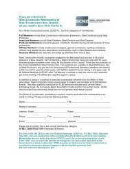
SCNZ –12: 20064 Contractual Relationships and Communication4.1 PRINCIPAL RESPONSIBLE FOR DESIGNNZS3910:1998 / NZIA SCC1: 2000 / NBC-G1: 1998PrincipalConstructionContractContractorPrincipal’sRepresentative:Engineer /Architect:Contractor’sRepresentativeContractualCommunicationDesignConsultants,QuantitySurveyor & ClerkSubcontractors &Suppliers17
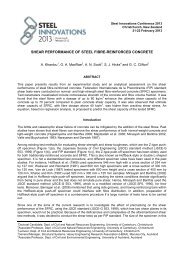
SCNZ –12: 20064.2 CONTRACTOR RESPONSIBLE FOR DESIGNFIDIC Conditions <strong>of</strong> Contract <strong>for</strong> Plant and Design-Build: 1999Design-BuildConstructionContractConstructionSubcontractEmployerDesign-BuildContractor<strong>Steelwork</strong>SubcontractorEmployer’sRepresentativeContractor’sRepresentative<strong>Steelwork</strong>Subcontractor’sRepresentativeDesignConsultants,QuantitySurveyor & ClerkDesignConsultants,QuantitySurveyor & ClerkFabricators,Riggers, QuantitySurveyorContractCommunicationSubcontractCommunication18
SCNZ –12: 20066 Contract <strong>Documentation</strong> Responsibilities6.1 RESPONSIBILITIES OF THE PRINCIPAL’S REPRESENTATIVEThe Principal’s Representative has roles defined in terms <strong>of</strong> the contract documents. ThePrincipal’s Representative is responsible <strong>for</strong> issuing contract documents and is the only person interms <strong>of</strong> the contract who can issue clarifications or variations to the contract documents. ThePrincipal’s Representative is there<strong>for</strong>e the only person under the contract, to be fully responsible<strong>for</strong> the completeness and co-ordination <strong>of</strong> the Contract Drawings and Specifications.A person accepting the role as Principal’s Representative should there<strong>for</strong>e be competent inmanaging the process <strong>of</strong> contract documentation development, co-ordination and administration.The Principal’s Representative has a fiduciary duty <strong>of</strong> care to both the Principal and theContractor to facilitate the administration <strong>of</strong> the Contract. There<strong>for</strong>e care should be taken toensure that the reliability or completeness <strong>of</strong> Contract Documents issued is not misrepresented.The Principal’s Representative <strong>of</strong>ten relies on design consultants to prepare Drawings andSpecifications <strong>for</strong> the Contract. The Principal’s Representative should there<strong>for</strong>e ensure that thedesign consultants have adequate documentation quality assurance systems in place and thatco-ordination between design consultants is satisfactorily completed be<strong>for</strong>e Drawings andSpecifications are issued to the Contractor.6.2 IDENTIFICATION OF DOCUMENTS<strong>Steelwork</strong> drawings, specifications and addenda should be clearly and completely identifiable asa work package. Drawings should be numbered and dated <strong>for</strong> purposes <strong>of</strong> identification. AllDrawings that need to be used to set out, measure quantities, detail and fabricate the structuralsteelwork need to be identified in a structural steelwork document schedule. These may includedrawings prepared by the architect, the structural engineer and mechanical services engineer,among others.Maintaining a common convention <strong>for</strong> the identification <strong>of</strong> drawing revisions assists in trackingdown the current construction document. The preferred convention <strong>for</strong> numbering drawingrevisions is to use numbers from 1 to x <strong>for</strong> pre-construction issue drawings. At, “ForConstruction”, issue the revision number is then made, 0. Further revisions during constructionshould be identified with alphabetic characters, A, B,….6.3 SUFFICIENCY OF DOCUMENTSThe Contract Documents are assumed to provide complete structural steel design drawingsclearly defining the work to be per<strong>for</strong>med and giving the size, section, material grade and thelocation <strong>of</strong> all members, connection types, floor levels, column centres and <strong>of</strong>fsets, and camber <strong>of</strong>members. There should be sufficient dimensions or references to common project grids to conveyaccurately the quantity and nature <strong>of</strong> the structural steel to be furnished. <strong>Structural</strong> steelspecifications should include any special requirements regulating the fabrication and erection <strong>of</strong>the structural steel.6.4 LIMITATIONS OF TENDER DOCUMENTSWhen it is required that a project be tendered using Documents that are sufficient <strong>for</strong> Tenderpurposes only, the Principal’s Representative should clearly and completely identify the limitations<strong>of</strong> the Tender Documents.Sufficient in<strong>for</strong>mation should be provided covering the steelwork portion <strong>of</strong> the works, in the <strong>for</strong>m<strong>of</strong> scope, drawings, section sizes, connection types, coatings, outline specifications, and other20
SCNZ –12: 2006descriptive data to enable the Contractor to assess the proposed Contract Works and prepare aknowledgeable bid. The Principal’s Representative should make the Contractor aware <strong>of</strong> thelimitations <strong>of</strong> the Tender <strong>Documentation</strong> and be able to identify the risks associated with thecontract works that have not been fully defined.6.5 DIMENSIONSThe set out and dimensioning <strong>of</strong> the structural skeleton <strong>of</strong> the building is one <strong>of</strong> the primaryarchitectural design tasks. Responsibility <strong>for</strong> this important task is <strong>of</strong>ten shared by the architectwith structural and building services engineering designers. The Principal’s Representativeshould ensure that dimensioning responsibilities are clearly defined <strong>for</strong> their particular project.Typically the architectural consultant will locate grids, finished floor levels, slab penetrations andbuilding envelope dimensions, within which the structural consultant sets out the structuralelements. The building services consultant will then refer to both the architectural and thestructural consultants drawings <strong>for</strong> setting out services. Co-ordination checks between thearchitect, structural and building services engineer prior to drawings being issued <strong>for</strong> constructionis there<strong>for</strong>e essential to ensure that all dimensioning in<strong>for</strong>mation is consistent.The structural skeleton should be fully and clearly defined to ensure that the finished surfaces,features and amenities <strong>of</strong> the building can be properly accommodated. Accurate set out anddimensioning <strong>of</strong> the structural elements is also necessary to ensure that the strength and inserviceper<strong>for</strong>mance <strong>of</strong> the structure is in accordance with the regulatory requirements <strong>of</strong> theBuilding <strong>Code</strong> and any special requirements <strong>of</strong> the Principal.In cases <strong>of</strong> discrepancies or ambiguities, between the structural steelwork drawings and thearchitectural drawings or drawings <strong>for</strong> other trades, the Contractor shall assume that the structuralsteelwork drawings govern <strong>for</strong> the following in<strong>for</strong>mation:• Steel member sizes, grades, cambers and connection details.• Set out <strong>of</strong> all main members in plan.• Set out <strong>of</strong> all main members in elevation.• Set out geometry <strong>for</strong> working points.When issued “For Construction”, the structural drawings are assumed to be complete andadequately accommodate the regulatory aspects <strong>of</strong> the design in terms <strong>of</strong> set out and structuralper<strong>for</strong>mance. Once issued “For Construction”, any changes to architectural or building servicesrequirements should there<strong>for</strong>e be made to accommodate the structure, already authorised to bebuilt. Where changes are made that have structural implications in terms <strong>of</strong> set out or structuralper<strong>for</strong>mance then the structural drawings should be appropriately amended and reissued.To ensure that the regulatory and per<strong>for</strong>mance aspects <strong>of</strong> the structural design are notcompromised by other trades, it is recommended that any in<strong>for</strong>mation or dimensions that mayaffect the regulatory and structural per<strong>for</strong>mance <strong>of</strong> the steelwork structure should be found on thestructural steelwork drawings. Once these are issued “For Construction”, the in<strong>for</strong>mation foundon the structural steelwork drawings should take precedence over in<strong>for</strong>mation found on drawings<strong>of</strong> other trades.In addition, construction <strong>of</strong> the Works described in the structural drawings will be commencedahead <strong>of</strong> the installation <strong>of</strong> building services and architectural finishes. In many casesarchitectural detailing and specific building services equipment types may not be finalised be<strong>for</strong>ethe structure is under construction. As a result, the issuing <strong>of</strong> structural steelwork drawingsshould be the focus <strong>of</strong> ef<strong>for</strong>ts to co-ordinate architectural and building services setting outin<strong>for</strong>mation.21
SCNZ –12: 20066.6 CO-ORDINATION OF DOCUMENTSThe Contractor is not responsible <strong>for</strong> ensuring that the Drawings are fully co-ordinated and withoutdiscrepancy.The Principal’s Representative should ensure that all in<strong>for</strong>mation necessary <strong>for</strong> the construction <strong>of</strong>the structural steelwork is fully and correctly documented. Any conflicts between architectural,building services and structural drawings should be resolved prior to being issued “ForConstruction’.Where drawings other than the structural steelwork drawings are to be referred to by theContractor <strong>for</strong> setting out the structural steelwork, these should be specifically identified within thestructural steelwork drawings. If it is difficult and time consuming <strong>for</strong> the Contractor to find therelevant design and setting out in<strong>for</strong>mation then there will inevitably be increased costsassociated in constructing the steelwork.Any portions <strong>of</strong> a drawing that have not been fully designed or co-ordinated by the Principal’sRepresentative at the time <strong>of</strong> being issued “For Construction”, should be clearly identified.6.7 “FOR CONSTRUCTION” AUTHORISATIONThe Contractor usually cannot proceed with the Contract Works, until the Drawings are released“For Construction”. “For Construction” issue drawings are assumed to fully and clearly define theContract Works without ambiguity. “For Construction” drawings and specifications are required bythe Contractor <strong>for</strong> authority to order material, prepare shop and erection drawings and commencefabrication <strong>of</strong> the Contract Works.6.8 DEVELOPMENT OF SHOP DRAWINGS<strong>Structural</strong> steelwork shop drawings are <strong>of</strong>ten prepared in three stages. The first stage is toconfirm quantities <strong>of</strong> steel sections and fittings so that an accurate order may be placed withsuppliers. This involves setting an accurate wire frame model <strong>of</strong> the structure. The second stageinvolves detailing the connections between the members. The third stage is to detail any servicepenetrations that may be required.Where the Principal’s Representative wishes to fast track issuing <strong>of</strong> “For Construction” steelworkdrawings and this has been communicated to the Contractor during the Tender process, it ispossible to stage the “For Construction” issue into three successive stages. These are: MaterialOrder, Connections and Services. The documents issued at each <strong>of</strong> these stages describecompleted in<strong>for</strong>mation that is not changed at the issue <strong>of</strong> drawings at each subsequent stage.Shop drawing preparation will be commenced at the issue <strong>of</strong> drawings <strong>for</strong> material order.However these will not typically be issued to the Principal’s Representative <strong>for</strong> review until “ForConstruction” drawings have been issued confirming connection and services accommodationrequirements.6.8.1 For Construction: Material OrderConfirmed member sizes and setting out in<strong>for</strong>mation in plan and elevation arerequired.This allows a shop drawing wire frame model to be developed by the Contractor,setting out the steel members relative to grids and floor levels. From these drawingsaccurate steel section quantities can be determined and orders placed with steelstockists.22
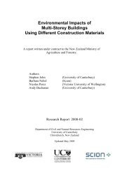
SCNZ –12: 20066.8.2 For Construction: ConnectionsConfirmed member to member connection details are required so that shop drawingscan be progressed to near completion. Plate, bolts and welding quantities can thenbe determined and orders placed.6.8.3 For Construction: ServicesConfirmed attachments and penetrations necessary to accommodate buildingservices such as sprinkler pipes, electrical cable trays, HVAC ductwork andarchitectural fittings.CONTRACT DOCUMENTSPRIMARYSTRUCTUREFOB. ITEMSMATERIALORDERCONNECTIONSSERVICES• Section sizes• Member setout• Standard• Non-standard• Bolts• HD Bolts• Cleats• Welds• Copes• Stiffeners• Fly-braces• Shear studs• Coatings• Penetrations• Rein<strong>for</strong>cement• FOB. fixings• Lift shaft• LMR• Stairs• Canopies• ACUSupports• BMUSupports• Balustrades• CladdingPanels• Fascias• SignsSHOP DRAWINGS23
SCNZ –12: 20066.9 DESIGN RESPONSIBILITYThe Principal’s Representative should provide the Contractor with complete and accuratecontract documents that give thorough in<strong>for</strong>mation, allowing the Contractor to correctly interpretthe design intent and to produce quality shop drawings.When the Principal’s Representative provides the design, drawings and specifications, theContractor is not responsible <strong>for</strong> the suitability, adequacy or legality <strong>of</strong> the design.6.10 RESPONSIBILITY FOR DIMENSIONSThe Principal’s Representative should provide sufficient and accurate dimensioning in<strong>for</strong>mationon the Drawings <strong>for</strong> the Contractor to be able to correctly set out the structural steelwork.The Contractor requires Contract Drawings describing the structural steelwork that include:Base plate and Grid set-out drawing; Floor plans with member set-out relative to grid and top <strong>of</strong>steel; Elevations <strong>of</strong> bracing frames and connection detail drawings. This in<strong>for</strong>mation may beprovided on a combination <strong>of</strong> cross-referenced and co-ordinated architectural, structural andbuilding services drawings. However the structural engineering drawings are the natural focus <strong>of</strong>structural steelwork in<strong>for</strong>mation. This is because the structural design and drawings should meetthe requirements <strong>of</strong> the architectural and building services design <strong>for</strong> the building as well assatisfy the structural per<strong>for</strong>mance requirements <strong>of</strong> the Principal and the regulatory authorities.Any in<strong>for</strong>mation, including member specification and set out, that affects the structuralper<strong>for</strong>mance <strong>of</strong> the structure, in terms <strong>of</strong> regulatory and design brief, should there<strong>for</strong>e normally befound on the structural drawings.Once issued “For Construction”, any changes made to the architectural and building servicesdesign that affects the structural steelwork should typically be made in conjunction with thestructural engineering drawings. This is to ensure that structural per<strong>for</strong>mance is notcompromised by the changes.Contract Drawings describing the structural steelwork are typically prepared as A1 drawings.However the use <strong>of</strong> A4 drawings <strong>for</strong> all non-standard connection details can be an effectiveapproach. This allows the details to be kept in an A4 file and minimises the need <strong>for</strong> re-issues <strong>of</strong>A1 connection drawings when only one detail on a sheet may be affected.6.11 SHOP DRAWING INSPECTION / REVIEWShop drawings prepared by the Contractor do not <strong>for</strong>m part <strong>of</strong> the Contract Documents andthere<strong>for</strong>e their review or inspection should not be regarded as part <strong>of</strong> the Principal’sRepresentative’s contract documentation quality assurance process. The purpose <strong>of</strong> theinspection <strong>of</strong> shop drawings is similar to the purpose <strong>of</strong> any inspections or reviews done by thePrincipal’s Representative, that is to assure the Principal’s Representative that the Contractorhas correctly interpreted the Contract Documents.The Principal’s Representative may issue Contract Documents prepared to a level <strong>of</strong> detail suchthat the Contractor decides not to prepare additional shop drawings. However the Principal’sRepresentative is responsible <strong>for</strong> the completeness and accuracy <strong>of</strong> all such drawings provided.When the Contractor prepares shop drawings, prints may be submitted to the Principal’sRepresentative <strong>for</strong> review and release <strong>for</strong> fabrication, if specifically required by the ContractDocuments. Typically the Contract Documents will give an allowance <strong>of</strong> seven, (7), calendar daysin the schedule, <strong>for</strong> the Principal’s Representative to return the shop drawings to the Contractor.Where possible this review time should be reduced so as to minimise material order andfabrication delays. Typically the dimensional set out <strong>of</strong> members and items calculated by the24
SCNZ –12: 2006detailer are not checked by the Principal’s Representative. Inspection and review <strong>of</strong> shopdrawings by the Principal’s Representative does not in any way relieve the responsibility <strong>of</strong> theContractor to correctly interpret the Contract Documents. As with other inspections per<strong>for</strong>med bythe Principal’s Representative, only portions <strong>of</strong> the Works may be selected <strong>for</strong> detailed review, soas to provide adequate assurance <strong>of</strong> the Contractor’s interpretation and compliance with therequirements <strong>of</strong> the Documents.Return <strong>of</strong> shop drawings is typically noted with the Principal’s Representative’s release <strong>for</strong>fabrication to continue on the reviewed portion, release subject to corrections as noted, or requestto correct and resubmit. The Contractor makes any corrections and furnishes corrected prints tothe Principal’s Representative. Where, following the review <strong>of</strong> the shop drawings, the Principal’sRepresentative wishes to make changes to the steelwork Drawings or Specifications, then aVariation should be ordered in accordance with the terms <strong>of</strong> the contract and may be subject to aclaim. Variations made at the shop drawing review stage are likely to have contract programmeand cost implications <strong>for</strong> the Principal. Any Variation that compromises the Contractor’s right andflexibility to determine the fabrication schedule necessary to meet the project’s requirements, islikely to have cost and contract programme implications.The role <strong>of</strong> the Detailer is to interpret the Contract Documents and prepare shop drawings <strong>for</strong>each item <strong>of</strong> steelwork suitable <strong>for</strong> construction tradespeople to fabricate and erect the items.The Contractor is not required to verify the accuracy <strong>of</strong> or co-ordinate Contract Drawings andSpecifications. Where the Principal’s Representative wishes to use a shop detailer to assist in coordination<strong>of</strong> Contract Drawings then the detailer should be engaged as part <strong>of</strong> the Principal’sRepresentative’s contract documentation development team.Where the Principal’s Representative wishes the Contractor to co-ordinate design andspecification activities <strong>of</strong> Subcontractors to the Contract Documents this should be clearly statedin the Contract Documents.Where the Contractor finds that Contract Drawings and Specifications are incomplete, containerrors or are inadequately co-ordinated with other trades work, then the Contractor shall issue a<strong>for</strong>mal Request For In<strong>for</strong>mation, (RFI), to the Principal’s Representative. Where the Principal’sRepresentative confirms that the Drawings or Specifications are incomplete or in error, then theContractor’s costs associated with preparing the RFI shall be considered as extra work <strong>for</strong> whichthe Contractor is entitled to compensation.25
26SCNZ –12: 2006
SCNZ –12: 20067 <strong>Steelwork</strong> Contract <strong>Documentation</strong>: GeneralRequirementsCompleted Contract Drawings should include the following:7.1 All STRUCTURAL STEELWORK DRAWINGS IDENTIFIEDAll structural steel items should be clearly located and identified on the Principal’sRepresentative’s structural steelwork Drawings. Where architectural, mechanical or electricaldrawings contain structural requirements, these should be co-ordinated with the structuralengineer’s drawings and clearly cross-referenced.7.2 PRINTED AT SCALE DRAWNThe Drawings should be issued at the scale in which they are drawn. Additional copies at areduced scale may be supplied to the Contractor upon request.7.3 CAD and 3D MODELLING FILESProvide clear direction as to the s<strong>of</strong>tware type, accuracy and completeness <strong>of</strong> CAD and 3Dmodelling files <strong>for</strong> direct use <strong>for</strong> member placement and other detailing requirements <strong>of</strong> the steelconstructors shop drawings. If CAD or 3D files are issued <strong>for</strong> use by the Contractor they shouldbe accompanied by configuration in<strong>for</strong>mation to allow correct printing <strong>of</strong> the documents.The requirements and preparation <strong>of</strong> steelwork shop drawings and the associated manufacturingin<strong>for</strong>mation system data required by steel constructors is a very important and specialist area notcovered by this document. In order to ensure best productivity is achieved in the steelconstruction process It is strongly recommended that the steel constructor engaged by theContractor manage the development <strong>of</strong> any structural steelwork shop drawings and associated 3-D modelling.7.4 COORDINATION WITH MECHANICAL, ELECTRICAL & ARCHITECTURALThe structural Drawings should be co-ordinated with architectural and mechanical requirements.7.5 SPECIFICATIONSThe Specifications should be customised to the particular project and be in agreement with theDrawings. The Specification <strong>for</strong> the Fabrication and Erection <strong>of</strong> <strong>Structural</strong> <strong>Steelwork</strong>, HERAReport R4-99, is a recommended base specification.7.6 STANDARD STEELWORK NOTESDepending on the particular job these generally should cover the following:• General• Abbreviations• <strong>Steelwork</strong> including: Weld classes and grades, structural bolts, holes, purlins, grouting under baseplates, painting, inspection and any other specific requirements• Drill-in fixings• Attachment to masonry• Attachment <strong>of</strong> timber• Special construction sequences required.27
SCNZ –12: 20067.7 DIMENSIONSShow setting out dimensions <strong>for</strong> all project grids and floor levels.Show setting out dimensions <strong>for</strong> all items <strong>of</strong> structural steelwork relative to project grids and floorlevel datums.7.8 MATERIALSProvide sizes and material grade <strong>of</strong> all members, beams, columns, and bolts, etc. Simplicity andrepetition result in cost savings. Standardise the use <strong>of</strong> AS 3679 G300 steel sections, AS 3679.1G250 steel flat bar and AS/NZS 3678 G250 steel plate.State whether section types may be substituted with welded or other similar hot rolled sections.Where non-standard welded beams are specified, ensure that the relevant flange and web platedimensions are in conjunction with flange to web welding requirements.Specify not infer, special requirements such as fracture critical material, Charpy V-notch testing,etc., on all required members and pieces.7.9 BRACING FRAME AND MEMBER SEISMIC CATEGORYThe seismic category and structural type <strong>of</strong> steel bracing frames shall be identified in terms <strong>of</strong> theNew Zealand Steel Structures Standard, NZS3404:1997. This is particularly where Specificationclauses <strong>for</strong> material, weld quality and inspection requirements may refer to frame or memberseismic category.7.10 MEMBER ORIENTATIONVerify orientation <strong>of</strong> columns on each plan.7.11 PRE-CAMBERIs the camber in<strong>for</strong>mation complete?7.12 SHEAR STUDSIdentify the size, number and spacing <strong>of</strong> shear studs.7.13 SPLICE LOCATIONSProvide specific column, truss, and girder splice details. Identify zones over which splice locationsmay be located to accommodate fabricators preferred locations <strong>for</strong> transport and section stocklengths.7.14 BASEPLATES AND CAST-IN PLATES / ITEMSComplete base plate and holding down requirements including base plate elevations <strong>for</strong> allcolumns, type <strong>of</strong> levelling system, material grade, diameter, embedment, hole pattern and size <strong>of</strong>holes, plate orientation, weld requirements.Complete cast-in plates / items and attached studs or welded rein<strong>for</strong>cing bar requirements,including level and location, material grade, plate orientation and weld requirements.28
SCNZ –12: 20067.15 PASSIVE FIRE PROTECTIONClearly indicate location, type, and limits <strong>of</strong> members requiring passive fire protection.7.16 PROTECTIVE COATINGSSpecial cleaning, passive fire protection, galvanising and painting systems (type, colour, exposed,etc.) and locations should be clearly located and identified on design drawings.7.17 SPECIAL ERECTION REQUIREMENTSClearly specify any special erection requirements.7.18 FOUNDATION PLAN• Clear and complete gridline set out• Location and orientation <strong>of</strong> all columns• Necessary dimensional in<strong>for</strong>mation relating columns to ground beams, insitu concrete piles, footings,etc• RL to TOC (Top <strong>of</strong> concrete)• H.D (Holding down) bolt detail including size, grade, embedment, bolting arrangement, corrosionprotection and any other specific detail• Base plate thickness, size and orientation, <strong>of</strong>fset (if any), bleed holes if necessary• Grouting details• Weld requirements7.19 TYPICAL FLOOR PLANComplete plan <strong>of</strong> structural steel <strong>for</strong> every level, checked <strong>for</strong> erectability and fully dimensionedincluding:• Clear grid layout• Member locations dimensioned from grids• Section, size and orientation <strong>of</strong> every member (particularly <strong>for</strong> non-symmetrical sections: PFC, Angles)• RL TOS (Top Of Steel)• Precamber• Designation <strong>for</strong> standard connections/splices and reference detail <strong>for</strong> specifically designedconnections/splices. Where possible use Industry Standard ref. <strong>Structural</strong> <strong>Steelwork</strong> Connection GuideSCNZ-15: 2006• Specific details <strong>of</strong> any services requirements showing location, dimensions and any other requirements• All relevant details interfacing other trades eg. pipe and underfloor penetrations• Concrete Floor: RL’s, thickness, steps, rebates, slopes, special rein<strong>for</strong>cement, shear studs, voids to betrimmed, ponding allowance assumed, etc• Timber Framing: Reference to details showing, connections, timber sizes, location relative to steelmember, any cleats or holes, etc• Any other specific items requiring coordination and setting out eg voids <strong>for</strong> stairs, lifts, concrete panels,spandrels, parapets, glazing, louvres, timber walls and bracing.7.20 ROOF PLANComplete fully dimensioned plan showing all members, particularly rafters, ties, eave members,outriggers and any canopy framing, checked <strong>for</strong> erectability and dimensioned, including:• Clear grid layout• Where possible, members dimensioned from grids• Accurate ro<strong>of</strong> pitch• Identify all ridge and/or valley lines and references to details29
SCNZ –12: 2006• Section, size and orientation every member (particularly <strong>for</strong> non-symmetrical sections- Purlins, PFCs,Angles)• Purlin span details eg. simple, double, lapped and lap length• No. <strong>of</strong> rows and types <strong>of</strong> bridging• If applicable- Type and location <strong>of</strong> ro<strong>of</strong> bracing and reference to connection details <strong>of</strong> same• If applicable- Type and location <strong>of</strong> fly bracing and reference to connection details <strong>of</strong> same• Type <strong>of</strong> purlin trimmers• Dimensions from grids and any other relevant in<strong>for</strong>mation relating to any openings eg skylights, accessladders, fans, walkways, etc• All relevant details interfacing other trades eg Timber Framing <strong>for</strong> Gutters and s<strong>of</strong>fits: Reference todetails showing, connections, timber sizes, location relative to steel member, any cleats or holes, etc.• Location and size <strong>of</strong> box gutters and supports• Reference to any other sections or details required <strong>for</strong> further in<strong>for</strong>mation.•7.21 ELEVATIONSComplete fully dimensioned elevation showing all members particularly “between floor” memberssuch as stair supports, lift shaft steel, trusses, K-braces, hangers etc and all connections.In<strong>for</strong>mation on drawings should include:• Clear grid layout• Member locations dimensioned from grids• Floor levels (RL’s)• Top <strong>of</strong> steel (TOS) that is not noted on plans• Type <strong>of</strong> wall bracing and reference to connection details <strong>of</strong> same• Dimensions from grids and any other relevant in<strong>for</strong>mation relating to any door and/or window openings• If applicable- Girt type, size, spacing and any other dimensional in<strong>for</strong>mation required to place them onwalls• If applicable- ro<strong>of</strong> slope, Apex RL, required purlin spacing• All connections not shown on plans7.22 CONNECTIONSIn the preparation <strong>of</strong> Contract Drawings, the Principal’s Representative has two basic choices inthe showing <strong>of</strong> connection details.The Principal’s Representative may specify standard connections from the <strong>Structural</strong> <strong>Steelwork</strong>Connections Guide, SCNZ-15: 2006. All the connections and connection types should beidentified by the full description e.g. WP-70-NC, WP-30-SWC, BPP-80. All requirements <strong>for</strong>bracing details, stiffeners, doubler plates, web or cope rein<strong>for</strong>cement or similar items necessary<strong>for</strong> the completeness <strong>of</strong> the design should be sized and shown in complete detail.The Principal’s Representative may fully design and detail connections <strong>for</strong> all conditions and inthis case the Principal’s Representative has the obligation to show all fastener sizes,arrangement, quantities, grades and specify all connection material and weld types, sizes andlengths <strong>for</strong> each individual member or part to be joined. All requirements <strong>for</strong> bracing details,stiffeners, doubler plates, web or cope rein<strong>for</strong>cement or similar items necessary <strong>for</strong> thecompleteness <strong>of</strong> the design should be sized and shown in complete detail.The Contractor may suggest alternative details to some connections based on theirsubcontractor’s most efficient shop and erection processes. However, such changes should be<strong>for</strong>warded to the Principal’s Representative <strong>for</strong> review and approval.In all cases, the release <strong>of</strong> the shop drawings by the Principal’s Representative constitutesacceptance by the Principal’s Representative <strong>of</strong> design responsibility <strong>for</strong> the structural adequacy<strong>of</strong> the connections shown on the shop drawings. Where design responsibility <strong>of</strong> some aspects <strong>of</strong>30
SCNZ –12: 2006the contract works is to be allocated to the Contractor this should be clearly stated in the ContractDocuments.Designation <strong>for</strong> standard connections/splices from <strong>Structural</strong> <strong>Steelwork</strong> Connection Guide SCNZ -15: 2006 should be shown on plans and elevations. Details relating to any specifically designedconnections/splices should include:• Bolt size and grade• Number, gauge and spacing <strong>of</strong> bolts• Plate thicknesses• Stiffener requirements• Weld details including category and inspection requirements• Copes• Packer plates• Connection details <strong>of</strong> any other members not shown on plans or elevations eg bracing elements,purlins, girts, etc• Any relevant details interfacing other trades not shown on plans or elevations• Precast concrete panels or stairs: Fixing details.31
32SCNZ –12: 2006
SCNZ –12: 20068 Preliminary <strong>Steelwork</strong> <strong>Documentation</strong>: GeneralRequirements8.1 GENERALDuring the development <strong>of</strong> a project design, prior to building contract documentation beinginitiated, many options are considered by the Principal and his or her design and cost consultants.Preliminary design documents are <strong>of</strong>ten prepared <strong>for</strong> the purposes <strong>of</strong> quantifying a design andassessing its cost. In this case, where incomplete drawings and specifications are to be used <strong>for</strong>preliminary pricing, the following are some recommendations <strong>for</strong> preliminary documentation thatwill allow realistic preliminary pricing in<strong>for</strong>mation to be prepared <strong>for</strong> structural steelwork. Thedocuments prepared will also be in a position to be readily upgraded to Contract <strong>Documentation</strong>status with the minimum amount <strong>of</strong> ef<strong>for</strong>t.Drawings and Specifications <strong>for</strong> preliminary pricing should include the following:8.2 SCOPE OF PRELIMINARY STRUCTURAL STEELWORK DOCUMENTSIDENTIFIEDAll structural steel items should be clearly located and identified on the preliminary structuralsteelwork Drawings. Exclusions should be clearly stated, such as stairs, handrails, embeddeditems, etc. The purpose <strong>of</strong> the preliminary drawing should be identified, ie. option selectionpurposes.8.3 SPECIFICATION CLAUSES ON DRAWINGSAll specification clauses that may be expected to affect pricing should be noted on the preliminarydrawings. eg. propping, precambering, surface treatment.8.4 DIMENSIONSDraw to scale and allow scaling <strong>for</strong> materials quantity measurement. Otherwise show setting outdimensions <strong>for</strong> all project grids, floor levels, all items <strong>of</strong> structural steelwork relative to project gridsand floor level datums.8.5 MATERIALS REQUIREDProvide sizes and material grade <strong>of</strong> all members, beams, columns, and bolts, etc. Standardise theuse <strong>of</strong> AS 3679 G300 steel sections, AS3679.1 G250 steel flat bar and AS/NZS 3678 G250 steelplate. Identify where special grades <strong>of</strong> steel are required, such as L0 and L15 steels.State whether section types may be substituted with welded or other similar hot rolled sections.8.6 MATERIALS & WELD TESTINGSpecify, not infer, special requirements such as through-thickness, Charpy V-notch andradiography / ultrasound weld testing, etc., on all required members and pieces.8.7 BRACING FRAME SEISMIC CATEGORYIdentify the primary method <strong>of</strong> providing seismic lateral bracing to the structure.The seismic category and structural type <strong>of</strong> steel bracing frames should be identified in terms <strong>of</strong>the New Zealand Steel Structures Standard, NZS3404:1997.33
SCNZ –12: 20068.8 PRE-CAMBERAre the members requiring precamber identified?8.9 SHEAR STUDSIdentify the diameter, typical welded height and number <strong>of</strong> shear studs per member or averagespacing <strong>of</strong> shear studs.8.10 CONNECTIONS & BASEPLATESAs structural steel fabrication is primarily involved with handling, cutting and joining steelmembers, it is important that the extent <strong>of</strong> connection work required is identified so that anaccurate estimate <strong>of</strong> fabrication time and cost may be made. Indication <strong>of</strong> the intendedconnection type and relevant design load ratios significantly help estimators quantify that cost. Astatement such as, ”All secondary beam connections to be WP30, all primary beam to columnconnections to be FE 50, unless noted otherwise….”, may cover much <strong>of</strong> the steelwork.Standard details should preferably reference <strong>Structural</strong> <strong>Steelwork</strong> Connection Guide SCNZ-15:2006 Non-standard details should be identified at least with the following identification system.Preferably use this identification system in conjunction with sketch details showing the typicalarrangement <strong>of</strong> the connection. Manual <strong>of</strong> Standard Connection Details <strong>for</strong> <strong>Structural</strong> <strong>Steelwork</strong>HERA Report R4-58, has over 55 different connection configuration sketches that can bereferenced or pasted into preliminary Drawings and Specifications. These are available as aCAD library.8.10.1 Fixing System :Identification should include the predominant fixing system <strong>of</strong> the member to the frame, eg.welding (W) or bolting (B).8.10.2 Design Action Type :The significant design action types that the connection should transfer should be identified, eg.tension (T), compression (C), moment (M) and shear (S).For example a non-standard welded connection transferring tension moment and shear would bedesignated W-T/M/S. A bolted connection transferring moment and shear would be designated,B-M/S.The connection details may then be fully developed, by the Principal’s Representative, tocoincide with the tendering process and commencement <strong>of</strong> detailing to ensure the detailing andfabricating processes will not be delayed. In addition, the Principal’s Representative shouldconsult with the Contractor regarding preferred practices <strong>for</strong> fabrication and erection. A predetailingmeeting between the Principal’s Representative and the Contractor may be appropriateto facilitate this exchange <strong>of</strong> in<strong>for</strong>mation. In the event that design loads or other in<strong>for</strong>mationnecessary <strong>for</strong> selection <strong>of</strong> standard connections is not shown on the contract documents, thisin<strong>for</strong>mation should be furnished to the Contractor in a timely manner.8.11 SPLICE LOCATIONSIdentify expected splice locations. Advise whether Contractor can adjust splice locations <strong>for</strong>standard section supply lengths.34
SCNZ –12: 20068.12 EMBEDDED ITEMS AND EDGE TRIMMERSIdentify embedded items and decking trimmers to concrete walls.8.13 MECHANICAL , ELECTRICAL PENETRATIONS & ARCHITECTURAL FIXINGSIdentify if penetrations to beams or additional fittings <strong>for</strong> architectural claddings are likely to berequired.8.14 PASSIVE FIRE PROTECTIONClearly indicate location, type, and limits <strong>of</strong> members requiring passive fire protection.8.15 PROTECTIVE COATINGSSpecial cleaning, passive fire protection, galvanising and painting systems (type, colour, exposed,etc.) and locations should be clearly located and identified on design drawings.8.16 SPECIAL ERECTION REQUIREMENTSClearly specify any special erection requirements.8.17 TEMPORARY BRACING REQUIREMENTSTemporary bracing requirements should be considered as part <strong>of</strong> the overall constructionmethodology. Consideration should be given as to how the structure will react in an unbracedstate.35
36SCNZ –12: 2006
SCNZ –12: 20069 <strong>Documentation</strong> Contacts ListDESIGN CONTACTS LISTProject Name:Site Address:Details <strong>of</strong> the parties involved in the design <strong>of</strong> this project are as follows:CompanyContact Person1 <strong>Structural</strong>2 Architect3 HVAC4 Mechanical5 Electrical6 Civil7 Sprinkler8 Main Contractor9 Steel ConstructorCompany:Address:Phone FaxEmailPage 137
38SCNZ –12: 2006
SCNZ –12: 200610 <strong>Documentation</strong> Responsibility ChecklistDOCUMENTATION RESPONSIBILITY CHECKLIST Page 1This checklist identifies the agreed responsibilities <strong>for</strong> the design and documentation <strong>of</strong> all items <strong>of</strong> structural steelwork within this project.Company:Address:1 GENERAL NOTES AND SPECIFICATIONS 2 PLANSProject:Date:Item Description Responsibility Date Item Description Responsibility Date1.1 Material grades specified <strong>for</strong> all structural items Struct. 2.1 All grids defined and dimensioned. Architect1.21.31.41.5Bolts completely specified (grade, installation,procedures)Welding completely specified (weld type, grade,quality, sizes)Oversize hole criteria given <strong>for</strong> the typicalconnection holes.Oversize hole criteria given <strong>for</strong> the anchor bolt/baseplate holes.Struct. 2.2 All member sizes and orientations specified. Struct.Struct. 2.3Plan location and orientation <strong>of</strong> each columnspecified.Struct.Struct. 2.4 Specific location <strong>of</strong> each beam dimensioned. Struct.Struct. 2.5Sufficient reference dimensions given in nonrectangularareas.1.6Paint, galvanising and metal spray requirementsspecified.Struct. 2.6 Beams requiring pre-cambering clearly identified. Struct.1.7 Paint and no-paint areas completely specified. Struct. 2.7 Shear studs specified. Struct.1.8Galvanized and metal spray areas completelyspecified.Struct. 2.81.9 Drill in or masonry anchors specified. Struct. 2.91.10 Standard notes complete. Struct. 2.101.11 Shop drawing review procedures specified. Struct. 2.111.12All material, fabrication and coating inspection andtesting requirements specified.1.13 All fabrication and erection tolerances specified. Struct. 2.131.14All special construction procedures and sequencesspecified.Details provided <strong>for</strong> any other special rein<strong>for</strong>cingplates to be included.The purlin span details provided. e.g. single,double, lapped and lap length.Ro<strong>of</strong> purlin bridging, fly bracing and light crossbracing clearly specified and located.Specific dimensions provided <strong>for</strong> trimming outopenings <strong>for</strong> other trades. e.g. Air conditions ducts,Stair/lift voidsStruct.Struct.Struct.Struct.Struct.Struct. 2.12 Gutter slopes and fall directions clearly identified. Struct.All relevant steelwork plans, elevations andconnection drawings and Electrical, HVAC,Mechanical and Architectural Drawings referencedand co-ordinated.Struct.Struct. 2.14 Standard connection specified (eg. WP30 NC) Struct.1.15 Passive fire protection requirements noted Struct. 2.15 Correct detail referencing Struct.1.16Member seismic categories specified <strong>for</strong> elements<strong>of</strong> lateral load resisting systems1.17 Fixings to timber elements specified Struct.Struct. 2.16 Other(Specify)1.18 Other(Specify)39
SCNZ –12: 2006DOCUMENTATION RESPONSIBILITY CHECKLIST Page 2This checklist identifies the agreed responsibilities <strong>for</strong> the design and documentation <strong>of</strong> all items <strong>of</strong> structural steelwork within this project.Company:Address:3 ELEVATIONS AND SECTIONS 4 CONNECTIONSProject:Date:Item Description Responsibility Date Item Description Responsibility Date3.1 All grids defined and dimensioned. Architect 4.1 Columns3.2 All member sizes and orientations specified. Struct. 4.1.1All base plates and hold down bolt connectionsdesigned, specified and sufficiently dimensioned.3.3 All RL's <strong>of</strong> bottom <strong>of</strong> base plates shown. Struct. 4.1.2Grout thickness' sufficient to contain the jackingnuts.3.4 All top <strong>of</strong> steel RL's (TOS) given. Struct. 4.1.3The bottom ends <strong>of</strong> the hold down bolts sufficientlycontained within the footings and sufficientlydimensioned.Struct.Struct.Struct.3.5 All column, rafter and beam splice locations given. Struct. 4.1.43.63.7"Between floor" member locations specificallydimensioned.Sufficient reference dimensions given in slopingareas.Struct. 4.1.5Struct. 4.1.6Top ends <strong>of</strong> the hold down bolts sufficiently coveredwith the finish floor and sufficiently dimensioned.All other construction items such as rebarunaffected by the hold down installation.The hold down bolt patterns sufficiently containedwithin the footings and sufficiently dimensioned.Struct.Struct.Struct.3.8Specific dimensions provided <strong>for</strong> trimming outopenings <strong>for</strong> other trades. e.g Window/dooropeningsStruct. 4.1.7If the hold down bolts are detailed without specialfabrication and erection approaches, i.e. within theallowances <strong>of</strong> Section 14 NZS 3404, will "plumband level" <strong>of</strong> the structural frame be routine.3.9Girts, hangers, fly braces and cross-bracingspecifically dimensioned and located.Struct. 4.1.8 Column to column splice details and locations Struct.3.10Supports <strong>for</strong> door opening machinery coordinatedwith door supplier.Struct. 4.1.9 If required, column caps specified Struct.3.11Standard connections fully specified (eg. WP30NC)Struct. 4.1.10 Other(Specify) Struct.3.12 Correct detail referencing Struct. 4.2 Beams3.13 Other(Specify) Struct. 4.2.1Other cast-in or site drilled connections designed,specified and sufficiently dimensioned.Struct.4.2.2Cast-in's sufficiently contained in the walls and/orfloor slabs.Struct.4.2.3All other construction items, such as rebar,unaffected by the cast-in or site drilled connectioninstallation.Struct.Struct.4.2.4 Beams to cast-ins or drilled on-site connections Struct.40
SCNZ –12: 2006DOCUMENTATION RESPONSIBILITY CHECKLIST Page 3This checklist identifies the agreed responsibilities <strong>for</strong> the design and documentation <strong>of</strong> all items <strong>of</strong> structural steelwork within this project.Company:Address:4 CONNECTIONS continued 5 STAIRSProject:Date:Item Description Responsibility Date Item Description Responsibility Date4.2 Beams continued 5.1 All relevant grids defined and dimensioned. Architect4.2.5 Beam to beam one-sided Struct. 5.2 All member sizes and orientations specified. Struct.4.2.6 Beam to beam two-sided Struct. 5.3Specific dimensioning given to locate the stairs inrelation to the main structure.Struct.4.2.7 Beam to beam splice Struct. 5.4 All RL's <strong>of</strong> bottom <strong>of</strong> base plates shown. Struct.4.3 Beam to Column 5.5All top <strong>of</strong> steel RL's (TOS) given and set downsnoted.Struct.4.3.1 Non-moment beam to column flange Struct. 5.6 All column splice elevations given. Struct.4.3.2 Non-moment beam to column web Struct. 5.7 "Between floor" members specifically dimensioned. Struct.4.3.3 Moment beam to column flange Struct. 5.84.3.4 Moment beam to column web Struct. 5.94.3.5 Beam on supporting column Struct. 5.10Sufficient reference dimensions given in slopingareas.Cast-in fixings to concrete work coordinated withconcrete drawings.All relevant steelwork plans, elevations andconnection Drawings and Architectural Drawingsreferenced and coordinated.4.3.6 Column supporting beam Struct. 5.11 Connections fully specified Struct.Struct.Struct.Struct.4.3.7 Other(Specify) Struct. 5.12 Correct detail referencing Struct.4.4 Bracing to beams or columns Struct. 5.13 Other(Specify) Struct.4.5 Connections <strong>for</strong> FOB items Struct.41
SCNZ –12: 2006DOCUMENTATION RESPONSIBILITY CHECKLIST Page 4This checklist identifies the agreed responsibilities <strong>for</strong> the design and documentation <strong>of</strong> all items <strong>of</strong> structural steelwork within this project.Company:Address:6 LIFT FRAMING 7 WALKWAYS AND ACCESS LADDERSProject:Date:Item Description Responsibility Date Item Description Responsibility Date6.1 All relevant grids defined and dimensioned. Architect 7.1 All relevant grids defined and dimensioned. Architect6.2 All member sizes and orientations specified. Struct. 7.2 All member sizes and orientations specified. Struct.6.3Specific dimensions given to locate lift farming inrelation to main structure.Struct. 7.3Specific dimensioning given to locate all framing inrelation to the main structure.6.4 All RL's <strong>of</strong> bottom <strong>of</strong> base plates shown. Struct. 7.4 All RL's <strong>of</strong> bottom <strong>of</strong> base plates shown. Struct.6.5All top <strong>of</strong> steel RL's (TOS) given and set downsnoted.Struct. 7.5All top <strong>of</strong> steel RL's (TOS) given and set downsnoted.6.6 All column splice elevations given. Struct. 7.6 All member splices located. Struct.Struct.Struct.6.7 "Between floor" members specifically dimensioned. Struct. 7.7 "Between floor" members specifically dimensioned. Struct.6.8All relevant steelwork plans, elevations andconnection Drawings and Electrical, Mechanicaland Architectural Drawings referenced andcoordinated.Struct. 7.86.9 Connections fully detailed Struct. 7.96.10 Correct details referencing Struct. 7.10Hand and guard-rails specified and set outdimensions given.Foot tread plate, foot mesh, ladder rungs andfixings specified and set out.All relevant steelwork plans, elevations andconnection Drawings and Electrical, HVAC,Sprinkler and Architectural Drawings referencedand co-ordinated.6.11 Other(Specify) Struct. 7.11 Connections fully detailed Struct.Struct.Struct.Struct.7.12 Correct detail referencing Struct.7.13 Other(Specify) Struct.42
SCNZ –12: 2006DOCUMENTATION RESPONSIBILITY CHECKLIST Page 5This checklist identifies the agreed responsibilities <strong>for</strong> the design and documentation <strong>of</strong> all items <strong>of</strong> structural steelwork within this project.Company:Address:8 OVERHEAD CRANE RUNWAY GIRDERS 9 HVAC/SPRINKLER/ELECTRICAL SUPPORTSProject:Date:Item Description Responsibility Date Item Description Responsibility Date8.1 All relevant grids defined and dimensioned. Architect 9.1 All relevant grids defined and dimensioned. Architect8.2 All member sizes and orientations specified. Struct. 9.2 All member sizes and orientations specified. Struct.8.3 All RL's <strong>of</strong> bottom <strong>of</strong> base plates shown. Struct. 9.38.4 All top <strong>of</strong> steel RL's (TOS) given. Struct. 9.48.5 Members specifically dimensioned. Struct. 9.5Specific dimensioning given to locate all theframing in relation to the main structure.All top <strong>of</strong> steel RL's (TOS) given and set downsnoted.All relevant steelwork plans, elevations andconnection Drawings and Electrical, HVAC,Sprinkler and Architectural Drawings referencedand co-ordinated.8.6 Pre-cambers specified. Struct. 9.6 Connections fully specified Struct.Struct.Struct.Struct.8.7 Special levelling tolerances specified. Struct. 9.7 Correct detail references Struct.8.8Crane rail and crane rail attachment systems togirders adequately specified.Struct. 9.8 Other(Specify) Struct.8.9 End buffers specified. Struct.8.108.118.12The design satisfies crane supplier requirements<strong>for</strong> serviceability and strength.Any foot tread plate, foot mesh and fixings specifiedand set out.All relevant steelwork plans, elevations andconnection Drawings and Electrical, HVAC,Sprinkler and Architectural Drawings referencedand co-ordinated.Struct.Struct.Struct.8.13 Girder splices located Struct.8.14 Connections fully detailed Struct.8.15 Correct detail referencing Struct.8.16 Other(Specify) Struct.43
SCNZ –12: 2006DOCUMENTATION RESPONSIBILITY CHECKLIST Page 6This checklist identifies the agreed responsibilities <strong>for</strong> the design and documentation <strong>of</strong> all items <strong>of</strong> structural steelwork within this project.Company:Address:10 CLADDING SYSTEMSProject:Date:Item Description Responsibility Date10.1 All relevant grids defined and dimensioned. Architect10.2 All member sizes and orientations specified. Struct.10.3Specific dimensioning given to locate any framing<strong>for</strong> cladding panels in relation to the main structure.Struct.10.4All top <strong>of</strong> steel RL's (TOS) given and set downsnoted.Struct.10.5 "Between floor" members specifically dimensioned. Struct.10.6Relevant steelwork plans, elevations andconnection Drawings, Architectural Drawings andany other proprietary drawings referenced and coordinated.Struct.10.7 Connections fully detailed Struct.10.8 Correct detail referencing Struct.10.9 Other(Specify) Struct.44
SCNZ –12: 200611 <strong>Structural</strong> <strong>Steelwork</strong> Drawings List<strong>Structural</strong> <strong>Steelwork</strong> Drawings ListList drawing numbers <strong>of</strong> all drawings necessary to prepare shop drawings, order materials, fabricate, coat and erect steelwork requiredas part <strong>of</strong> the contract works.Project: Company:Date: Address:23Drawing Category1 General Notes and Specifications4 Plans5678 Elevations and Sections910111213 Connections1415161718 Stairs1920212223 Lift Framing2425262728 Walkways and Access Ladders29303132 Overhead Crane Runway Girders33343536 HVAC / Sprinker / Electrical Supports37383940 Cladding Systems4142434445464748Drawing TitleDrawing No.Due dateOther Referenced DrawingsArchitect HVAC Mechanical Electrical Civil Sprinkler Main Contractor Other45
46SCNZ –12: 2006
SCNZ –12: 200612 <strong>Documentation</strong> Completion ChecklistsSTEELWORK DRAWING COMPLETION CHECKLIST Page 1Project Name: Company:Address:Drawing Type: General Notes and Specifications Drawing Number: Revision:Drawing Title: Issue Purpose: Issue Date:Contact: Phone:Other Non-<strong>Steelwork</strong> Drawings ReferencedConsultant Drawing Aspect Governed Consultant Drawing Aspect GovernedArchitect CivilHVAC SprinklerMechanical Main ContractorElectrical OtherItem Description Issue Category Completion Checked1.1 Material grades specified <strong>for</strong> all structural itemsM1.2 Bolts completely specified (grade, installation, procedures)C1.3 Welding completely specified (weld type, grade, quality, sizes)C1.4 Oversize hole criteria given <strong>for</strong> the typical connection holes.C1.5 Oversize hole criteria given <strong>for</strong> the anchor bolt/base plate holes.C1.6 Paint, galvanising and metal spray requirements specified.C1.7 Paint and no-paint areas completely specified.C1.8 Galvanized and metal spray areas completely specified.C1.9 Drill in or masonry anchors specified.C1.1 Standard notes complete.C1.11 Shop drawing review procedures specified.M1.12All material, fabrication and coating inspection and testing requirementsMspecified.1.13 All fabrication and erection tolerances specified.C1.14 All special construction procedures and sequences specified.C1.15 Passive fire protection requirements notedC1.16Member seismic categories specified <strong>for</strong> elements <strong>of</strong> lateral load resistingMsystems1.17 Fixings to timber elements specifiedM1.18 Other (specify)CCommentsNote: For Material Order Issue, all category M items must be checked; For Construction Issue, all category M and C items must be checked.47
SCNZ –12: 2006STEELWORK DRAWING COMPLETION CHECKLIST Page 2Project Name: Company:Address:Drawing Type Plans Drawing Number: RevisionDrawing Title Issue Purpose Issue DateContact PhoneOther Non-<strong>Steelwork</strong> Drawings ReferencedConsultant Drawing Aspect Governed Consultant Drawing Aspect GovernedArchitect CivilHVAC SprinklerMechanical Main ContractorElectrical OtherItem Description Issue Category Completion Checked Comments2.1All grids defined and dimensioned.M2.2All member sizes and orientations specified.M2.3Plan location and orientation <strong>of</strong> each column specified.M2.4Specific location <strong>of</strong> each beam dimensioned.M2.5Sufficient reference dimensions given in non-rectangular areas.M2.6Beams requiring pre-cambering clearly identified.M2.7Shear studs specified.C2.8Details provided <strong>for</strong> any other special rein<strong>for</strong>cing plates to be included.C2.9The purlin span details provided. e.g. single, double, lapped and lap length.C2.10Ro<strong>of</strong> purlin bridging, fly bracing and light cross bracing clearly specified andClocated.2.11Specific dimensions provided <strong>for</strong> trimming out openings <strong>for</strong> other trades. e.g. AirCconditions ducts, Stair/lift voids2.12Gutter slopes and fall directions clearly identified.C2.13All relevant steelwork plans, elevations and connection drawings and Electrical,CHVAC, Mechanical and Architectural Drawings referenced and co-ordinated.2.14 Standard connection specified (eg. WP30 NC)C2.15 Correct detail referencingC2.16 Other (specify)CNote: For Material Order Issue, all category M items must be checked; For Construction Issue, all category M and C items must be checked.48
SCNZ –12: 2006STEELWORK DRAWING COMPLETION CHECKLIST Page 3Project Name: Company:Address:Drawing Type Elevations and Sections Drawing Number: RevisionDrawing Title Issue Purpose Issue DateContact PhoneOther Non-<strong>Steelwork</strong> Drawings ReferencedConsultant Drawing Aspect Governed Consultant Drawing Aspect GovernedArchitect CivilHVAC SprinklerMechanical Main ContractorElectrical Other3.13.23.33.43.53.63.73.83.93.103.113.123.13Item Description Issue Category Completion Checked CommentsAll grids defined and dimensioned.MAll member sizes and orientations specified.All RL's <strong>of</strong> bottom <strong>of</strong> base plates shown.All top <strong>of</strong> steel RL's (TOS) given.All column, rafter and beam splice locations given."Between floor" member locations specifically dimensioned.Sufficient reference dimensions given in sloping areas.Specific dimensions provided <strong>for</strong> trimming out openings <strong>for</strong> other trades. e.gWindow/door openingsGirts, hangers, fly braces and cross-bracing specifically dimensioned andlocated.Supports <strong>for</strong> door opening machinery coordinated with door supplier.Standard connections fully specified (eg. WP30 NC)Correct detail referencingOther (specify)MMMMMMCCCCCCNote: For Material Order Issue, all category M items must be checked; For Construction Issue, all category M and C items must be checked.49
SCNZ –12: 2006STEELWORK DRAWING COMPLETION CHECKLIST Page 4Project Name: Company:Address:Drawing Type Connections Drawing Number: RevisionDrawing Title Issue Purpose Issue DateIssuing Company Contact PhoneOther Non-<strong>Steelwork</strong> Drawings ReferencedConsultant Drawing Aspect Governed Consultant Drawing Aspect GovernedArchitect CivilHVAC SprinklerMechanical Main ContractorElectrical Other4.1Item Description Issue Category Completion Checked CommentsColumns4.1.14.1.24.1.34.1.44.1.54.1.64.1.74.1.84.1.94.2All base plates and hold down bolt connections designed, specified andsufficiently dimensioned. *Grout thickness' sufficient to contain the jacking nuts.The bottom ends <strong>of</strong> the hold down bolts sufficiently contained within thefootings and sufficiently dimensioned.Top ends <strong>of</strong> the hold down bolts sufficiently covered with the finish floor andsufficiently dimensioned.All other construction items such as rebar unaffected by the hold downinstallation.The hold down bolt patterns sufficiently contained within the footings andsufficiently dimensioned.If the hold down bolts are detailed without special fabrication and erectionapproaches, i.e. within the allowances <strong>of</strong> Section 14 NZS 3404, will "plumb andColumn to column splice details and locations *If required, column caps specifiedBeamsMMMMMMCCC4.2.14.2.24.2.34.2.4Other cast-in or site drilled connections designed, specified and sufficientlydimensioned. *Cast-in's sufficiently contained in the walls and/or floor slabs.All other construction items, such as rebar, unaffected by the cast-in or sitedrilled connection installation.Beams to cast-ins or drilled on-site connections *4.2.5 Beam to beam one-sided *C4.2.6Beam to beam two-sided *4.2.7 Beam to beam splice *C4.3Beam to Column *CCCCC4.3.1 Non-moment beam to column flange *C4.3.2 Non-moment beam to column web *C4.3.3Moment beam to column flange *4.3.4 Moment beam to column web *C4.3.5Beam to supporting column *4.3.6 Column supporting beam *C4.4Bracing to beams or Columns *4.5 Connections <strong>for</strong> FOB items *C4.6Other (specify)Note: For Material Order Issue, all category M items must be checked; For Construction Issue, all category M and C items must be checked.* Refer SCNZ-12 SteelDoc <strong>for</strong> minimum detailing in<strong>for</strong>mation required.CCCC50
SCNZ –12: 2006STEELWORK DRAWING COMPLETION CHECKLIST Page 5Project Name: Company:Address:Drawing Type Stairs Drawing Number: RevisionDrawing Title Issue Purpose Issue DateIssuing Company Contact PhoneOther Non-<strong>Steelwork</strong> Drawings ReferencedConsultant Drawing Aspect Governed Consultant Drawing Aspect GovernedArchitect CivilHVAC SprinklerMechanical Main ContractorElectrical Other5.15.25.35.45.55.65.75.85.95.105.115.125.13Item Description Issue Category Completion Checked CommentsAll relevant grids defined and dimensioned.MAll member sizes and orientations specified.MSpecific dimensioning given to locate the stairs in relation to the main structure.MAll RL's <strong>of</strong> bottom <strong>of</strong> base plates shown.MAll top <strong>of</strong> steel RL's (TOS) given and set downs noted.MAll column splice elevations given.M"Between floor" members specifically dimensioned.MSufficient reference dimensions given in sloping areas.MCast-in fixings to concrete work coordinated with concrete drawings.MAll relevant steelwork plans, elevations and connection Drawings andArchitectural Drawings referenced and coordinated.Connections fully specified *Correct detail referencingOther (specify)CCCCNote: For Material Order Issue, all category M items must be checked; For Construction Issue, all category M and C items must be checked.* Refer SCNZ-12 SteelDoc <strong>for</strong> minimum detailing in<strong>for</strong>mation required.51
SCNZ –12: 2006STEELWORK DRAWING COMPLETION CHECKLIST Page 6Project Name: Company:Address:Drawing Type Lift Framing Drawing Number: RevisionDrawing Title Issue Purpose Issue DateContact PhoneOther Non-<strong>Steelwork</strong> Drawings ReferencedConsultant Drawing Aspect Governed Consultant Drawing Aspect GovernedArchitect CivilHVAC SprinklerMechanical Main ContractorElectrical Other6.16.26.36.46.56.66.76.8Item Description Issue Category Completion Checked CommentsAll relevant grids defined and dimensioned.MAll member sizes and orientations specified.MSpecific dimensions given to locate lift farming in relation to main structure.MAll RL's <strong>of</strong> bottom <strong>of</strong> base plates shown.MAll top <strong>of</strong> steel RL's (TOS) given and set downs noted.MAll column splice elevations given.M"Between floor" members specifically dimensioned.MAll relevant steelwork plans, elevations and connection Drawings and Electrical,Mechanical and Architectural Drawings referenced and coordinated.C6.9 Connections fully detailed *C6.10 Correct detail referencingC6.11Other (specify)CNote: For Material Order Issue, all category M items must be checked; For Construction Issue, all category M and C items must be checked.* Refer SCNZ-12 SteelDoc <strong>for</strong> minimum detailing in<strong>for</strong>mation required.52
SCNZ –12: 2006STEELWORK DRAWING COMPLETION CHECKLIST Page 7Project Name: Company:Address:Drawing Type Walkways and Access Ladders Drawing Number: RevisionDrawing Title Issue Purpose Issue DateContact PhoneOther Non-<strong>Steelwork</strong> Drawings ReferencedConsultant Drawing Aspect Governed Consultant Drawing Aspect GovernedArchitect CivilHVAC SprinklerMechanical Main ContractorElectrical Other7.17.27.37.47.57.67.77.87.97.10Item Description Issue Category Completion Checked CommentsAll relevant grids defined and dimensioned.MAll member sizes and orientations specified.MSpecific dimensioning given to locate all framing in relation to the mainstructure.All RL's <strong>of</strong> bottom <strong>of</strong> base plates shown.All top <strong>of</strong> steel RL's (TOS) given and set downs noted.All member splices located."Between floor" members specifically dimensioned.Hand and guard-rails specified and set out dimensions given.Foot tread plate, foot mesh, ladder rungs and fixings specified and set out.All relevant steelwork plans, elevations and connection Drawings and Electrical,HVAC, Sprinkler and Architectural Drawings referenced and co-ordinated.MMMMMMMM7.11 Connections fully detailed *C7.127.13Correct detail referencingOther (specify)CCNote: For Material Order Issue, all category M items must be checked; For Construction Issue, all category M and C items must be checked.* Refer SCNZ-12 SteelDoc <strong>for</strong> minimum detailing in<strong>for</strong>mation required.53
SCNZ –12: 2006STEELWORK DRAWING COMPLETION CHECKLIST Page 8Project Name: Company:Address:Drawing Type Overhead Crane Runway Girders Drawing Number: RevisionDrawing Title Issue Purpose Issue DateIssuing Company Contact PhoneOther Non-<strong>Steelwork</strong> Drawings ReferencedConsultant Drawing Aspect Governed Consultant Drawing Aspect GovernedArchitect CivilHVAC SprinklerMechanical Main ContractorElectrical OtherItem Description Issue Category Completion Checked Comments8.1All relevant grids defined and dimensioned.M8.28.38.48.58.68.78.88.98.10All member sizes and orientations specified.All RL's <strong>of</strong> bottom <strong>of</strong> base plates shown.All top <strong>of</strong> steel RL's (TOS) given.Members specifically dimensioned.Pre-cambers specified.Special levelling tolerances specified.Crane rail and crane rail attachment systems to girders adequately specified.End buffers specified.The design satisfies crane supplier requirements <strong>for</strong> serviceability and strength.MMMMMCCCM8.118.12Any foot tread plate, foot mesh and fixings specified and set out.All relevant steelwork plans, elevations and connection Drawings and Electrical,HVAC, Sprinkler and Architectural Drawings referenced and co-ordinated.MC8.13Girder splices locatedC8.14 Connections fully detailed *C8.158.16Correct detail referencingOther (specify)CCNote: For Material Order Issue, all category M items must be checked; For Construction Issue, all category M and C items must be checked.* Refer SCNZ-12 SteelDoc <strong>for</strong> minimum detailing in<strong>for</strong>mation required.54
SCNZ –12: 2006STEELWORK DRAWING COMPLETION CHECKLIST Page 9Project Name: Company:Address:Drawing Type HVAC / Sprinkler / Electrical Supports Drawing Number: RevisionDrawing Title Issue Purpose Issue DateContact PhoneOther Non-<strong>Steelwork</strong> Drawings ReferencedConsultant Drawing Aspect Governed Consultant Drawing Aspect GovernedArchitect CivilHVAC SprinklerMechanical Main ContractorElectrical Other9.19.29.39.4Item Description Issue Category Completion Checked CommentsAll relevant grids defined and dimensioned.MAll member sizes and orientations specified.MSpecific dimensioning given to locate all the framing in relation to the mainstructure.All top <strong>of</strong> steel RL's (TOS) given and set downs noted.MM9.5All relevant steelwork plans, elevations and connection Drawings and Electrical,HVAC, Sprinkler and Architectural Drawings referenced and co-ordinated.C9.6Connections fully specified *C9.7 Correct detail referencesC9.8 Other (specify)C* Refer SCNZ-12 SteelDoc <strong>for</strong> minimum detailing in<strong>for</strong>mation required.55
SCNZ –12: 2006STEELWORK DRAWING COMPLETION CHECKLIST Page 10Project Name: Company:Address:Drawing Type Cladding Systems Drawing Number: RevisionDrawing Title Issue Purpose Issue DateContact PhoneOther Non-<strong>Steelwork</strong> Drawings ReferencedConsultant Drawing Aspect Governed Consultant Drawing Aspect GovernedArchitect CivilHVAC SprinklerMechanical Main ContractorElectrical OtherItem DescriptionIssue Category10.1All relevant grids defined and dimensioned.M10.2 All member sizes and orientations specified.M10.3Specific dimensioning given to locate any framing <strong>for</strong> cladding panels in relationto the main structure.M10.4All top <strong>of</strong> steel RL's (TOS) given and set downs noted.M10.5 "Between floor" members specifically dimensioned.M10.6Relevant steelwork plans, elevations and connection Drawings, ArchitecturalDrawings and any other proprietary drawings referenced and co-ordinated.C10.7Connections fully detailedC10.8Correct detail referencing *C10.9Other (specify)CCompletion Checked CommentsNote: For Material Order Issue, all category M items must be checked; For Construction Issue, all category M and C items must be checked.* Refer SCNZ-12 SteelDoc <strong>for</strong> minimum detailing in<strong>for</strong>mation required.56
SCNZ –12: 200613 SteelDoc <strong>Documentation</strong> Checklist S<strong>of</strong>tware13.1 Introduction<strong>STEELDOC</strong> is a Micros<strong>of</strong>t Windows based application developed with Micros<strong>of</strong>t Visual Basic 6.0and Excel. The program has been developed to help streamline <strong>of</strong>fice quality control by quicklypreparing checklists <strong>for</strong> each structural steelwork drawing in an easy to use <strong>for</strong>mat.In addition to assisting in the process <strong>of</strong> ensuring completeness <strong>of</strong> drawings, the program alsohelps facilitates the coordination <strong>of</strong> all <strong>of</strong> the contract documentation that relate to the steelworkcomponent <strong>of</strong> the project.The program has been based around the commonly accepted practice <strong>of</strong> categorizing steelworkdrawings in the following manner:• Primary Structure (Floor structure, bracing elements, wall and ro<strong>of</strong> structural elements)1. General notes and specifications2. Plans3. Elevations4. Connections• Free On Board Items (canopies, stairs, lift assemblies, walkways, ladders, HVAC plantsupports, gantry girders)Provided the drawing set is prepared on this manner, a check list appropriate <strong>for</strong> each structuraldrawing will be prepared. The program will generate checklists <strong>for</strong> up to 100 drawings.The file should be run on an IBM PC or compatible using Micros<strong>of</strong>t Windows XP and Excel XP orlater versions.13.2 InstallationCreate a folder on the local drive <strong>of</strong> the users computer (e.g. C:\<strong>STEELDOC</strong>)Copy “SteelDoc.xls” into the SteelDoc folder. The program cannot be run directly from the CDRom.13.3 Input and Output ProceduresThe various pages <strong>of</strong> the program are accessed from a single menu, see figure 1. To make theprogram easy to navigate the inputting functions have been separated into initial setup in<strong>for</strong>mationand the checklists.Each sheet <strong>of</strong> the program may be printed by clicking the print button on the spreadsheet tool bar.13.3.1 Step 1: Initial Setup – Design Consultants Contact Details SelectionSelect the intial setup box. A second box will appear to the right <strong>of</strong> the first. Click on the dropdown box button. The user will be given the choice <strong>of</strong> three page options. Select Contact Detailsand then click the Go button, refer figure 1.The project details, including contact details can be inputted into the programme by clicking on theappropriate cell and typing in the required in<strong>for</strong>mation. Data from other Excel spreadsheets mayalso be input using the Copy and Paste Special functions or control q. When the Contact Listsheet is opened a pop up box will remind users <strong>of</strong> the correct paste procedure to avoid <strong>for</strong>mattingproblems.57
SCNZ –12: 2006SteelDoc 1.0bInitial SetupContact DetailsGoCheck ListsClick to activate drop down boxFigure 1 Main menu - navigation featuresIn<strong>for</strong>mation in the sheet may be amended by clicking on the required cell and using standardExcel spreadsheet editing proceduresDelete single contact recordDelete all dataNavigation buttons.Figure 2 Contact List PageThe user may either clear data one row at a time by clicking on any cell in the required row andselecting the Delete selected contact button or by using the Reset button to clear all the contactin<strong>for</strong>mation, see figure 2. A pop up box will appear following activation <strong>of</strong> the Reset button to allowusers the chance to confirm their intention to delete all contact details.There is no requirement to save inputted data prior to exiting the page. To return to the mainmenu click the Return to Menu button located at the bottom <strong>of</strong> the page, see figure 2.58
SCNZ –12: 2006Alternatively the Drawing List page can accessed by clicking the appropriate box at the bottom <strong>of</strong>the page, refer figure 2.13.3.2 Step 2: Initial Setup – Contract Drawing List SelectionThe contract drawing list page may be accessed either by activating the initial setup in<strong>for</strong>mationbutton and selecting the drawing list option from the drop down box as per step 1 or from one <strong>of</strong>the other two initial setup in<strong>for</strong>mation pages (Design Consultant’s Contact List and DesignConsultants Task Checklist). The minimum in<strong>for</strong>mation required <strong>for</strong> SteelDoc is the structuraldrawing list with drawings categorized as previously discussed in the introduction section. Toallow relevant in<strong>for</strong>mation from other documents to be easily found <strong>for</strong> coordination and checkingpurposes, it is recommended that the appropriate other referenced documents boxes be filled in,see figure 3The project details will automatically appear on the page if the Design Consultant Contacts Listsheet has been completed. The user may add the date by clicking on the appropriate cell andtyping the required in<strong>for</strong>mation.Delete all dataSave dataDelete single line <strong>of</strong> dataNavigation buttonsFigure 3 Contact drawing list pageData entry can either be by clicking on the appropriate cell and typing the required in<strong>for</strong>mation orby copying and pasting columns <strong>of</strong> data from other spreadsheets. If data is inputted from otherspreadsheets it should be done so as single columns rather than as blocks. To avoid <strong>for</strong>mattingproblems, data should be pasted using either control q or the paste special function. The usermust nominate <strong>for</strong> each drawing the appropriate drawing category. The drawing category box isactivated by clicking on the right hand side <strong>of</strong> the drawing category cell.To remove a single drawing entry, click on any cell on the line to be removed and select theDelete selected drawing button located on the top left hand side <strong>of</strong> the screen. To clear all datafrom the contract drawing list page, activate the Reset button also located on the top left handside <strong>of</strong> the screen. To avoid erroneously deleting all the data, the program asks the user toconfirm their intention to reset the page.To edit data, click on the required cell and retype the correct data. To close line gaps caused byusing the Delete selected line button or to rearrange the order <strong>of</strong> the drawing list, the copy andcontrol q or paste special functions can be used. If during the course <strong>of</strong> editing in<strong>for</strong>mation the59
SCNZ –12: 2006screen <strong>for</strong>matting is lost, it can be restored by using the reset function. The user should note thatusing this function will in addition to restoring lost <strong>for</strong>matting also remove all data from the page.To save data, click on the Update button located top left side <strong>of</strong> the screen be<strong>for</strong>e exiting thescreen.The user can either return to the previous page by activating the Contact List button located atthe top right hand side <strong>of</strong> the sheet or move to the next initial setup page via the Task Checklistbutton. A final option is to return to the main menu page via the Return to Menu button, seefigure 3.13.3.3 Step 3: Initial Setup – Design Consultant Task Checklist SelectionThe Task Allocation page can be accessed from either the Menu page as per step 1 or theDrawing List page.The tasks listed itemize all the in<strong>for</strong>mation required to be included in the structural steelworkdesign documentation. The majority <strong>of</strong> the in<strong>for</strong>mation required will be provided by the <strong>Structural</strong>Engineer. In recognition <strong>of</strong> this fact, most <strong>of</strong> the tasks are allocated by default to the <strong>Structural</strong>Engineer. To reset to this default position, click the Reset button located at the top and bottom <strong>of</strong>the page, refer figure 4. However, there are tasks that will be the responsibility <strong>of</strong> other members<strong>of</strong> the design team ie specifying coating systems or coordinating drawings. To ensure tasks donot fall through the cracks so to speak, the Principal Consultant can use this page as a tool toensure that all the tasks have been allocated to the design team and that everyone is aware <strong>of</strong>their responsibilities in this regard.Navigation buttonsActivated drop down boxFigure 4 Consultant task checklistTo change the task allocation to another party, click the tab on the appropriate responsibilitycolumn cell, this will activate a drop down box, see figure 4. Click on the required party to changeto the task allocation.The data will automatically be saved once the page is completed. To return to the main menu orthe previous page, click on the appropriate navigation buttons located at the top and bottom righthand side <strong>of</strong> the page, refer figure 4.60
SCNZ –12: 200613.3.4 Step 4: Check Lists SelectionThe check list pages are accessed from the menu page, see figure 5. The program will generatea separate checklist <strong>for</strong> each drawing. The drawings are accessed by category type. Click thecheck list button on the menu page to activate a second box. Once the drop down button hasbeen clicked, a list <strong>of</strong> the drawing categories is displayed from which the user may chose. Selectthe drawing category, in this instance Plans, see figure 5, followed by the Go button.Once in the <strong>Steelwork</strong> Drawing Completion Check List page, the required drawing is found byclicking on the drawing list. A drop down box listing all the drawings under the chosen drawingcategory will appear, see figure 6. The sheet will now display the relevant drawing in<strong>for</strong>mationpreviously inputted in steps 1 and 2. Users will note <strong>for</strong> each task there is an issue categorydesignated M or C which refers to Material Order and Connections. This is discussed in section6.8SteelDoc 1.0bInitial SetupCheck ListsPlansGoFigure 5 Checklist option selected from menu pageClick to activate drop boxPlan drawings listedFigure 6 Completion checklist page - drawing title drop down box activated61
SCNZ –12: 2006To access drawings with a different drawing category, click on the drawing type drop down button,see figure 7. This will activate a drop down box with a selection <strong>of</strong> categories the user maychoose from. To pick the required drawing within the category, repeat the procedure discussed inthe previous paragraph.The input options <strong>for</strong> the checklist pages are as follows:• Once a task is completed the appropriate box may be clicked to record a tick, see figure 7• Comments may also be recorded <strong>for</strong> each task in the column located on the right handside <strong>of</strong> the sheet. To input data click on the appropriate cell and begin typing• Comments may also be added to the other non structural drawings referenced portion <strong>of</strong>the page. For example an architectural drawing referenced may contain set outin<strong>for</strong>mation, the Aspect Governed column allows the user to record this was the reason<strong>for</strong> referencing this drawing. The intention is that this will make checking and coordinatingthe drawings easier in the futureClick to activate drop boxDrawing categoriesClick box to leave tickFigure 7 Completion checklist page - drawing type drop down box activatedTo save the inputted in<strong>for</strong>mation, the Save button located on the top right hand side <strong>of</strong> the pagemust be activated.To clear all the user inputted data <strong>for</strong> the drawing type on the screen (this may involve severaldrawings), click the Reset button. Be<strong>for</strong>e the data is deleted the user will be asked to confirm thisrequest. Activating the reset button will also remove all the drawing titles displayed in the drawingtitle box. The drawing titles can be reinstated using the following steps.• Exit the completion check list page via the Return to Menu button• Access the contract drawing list from the initial setup menu• Once in the contract drawing list page click the Update button• Return to the appropriate checklist page. The deleted drawing titles should now bedisplayed if the drawing title drop down box is activated.If there is more than one drawing per drawing type and it is only required to delete checklist data<strong>for</strong> a single drawing, the user may undertake the following steps:• Exit the Completion Checklist page and return to the Contract Drawing List input screenvia the initial setup menu62
SCNZ –12: 2006• Delete the appropriate drawing using the Delete selected drawing button• Click the update button• Retype the deleted drawing title data• Select the Update button• Return to the original checklist page• Activate the drawing title drop down box to select the required drawing title.To save inputted or edited in<strong>for</strong>mation, click the Save button located on the top right hand side <strong>of</strong>the page.To return to the main menu, click the Return to Menu button located top hand corner <strong>of</strong> page,see figure 7.63
64SCNZ –12: 2006
SCNZ –12: 200614 ConclusionThe use <strong>of</strong> structural steelwork in construction in New Zealand is rapidly increasing. While thedesign and construction methods used is constantly changing the three fundamentals <strong>of</strong> gooddesign documentation remain. They are clarity <strong>of</strong> presentation, lack <strong>of</strong> ambiguity andcompleteness in defining the Contract Works.The Principal’s Representative and the design consultants that prepare the Contract Documentsthat he or she issues on behalf <strong>of</strong> the Principal, have a pivotal role in facilitating the continuingdevelopment <strong>of</strong> a reliable and cost effective construction industry in New Zealand.SteelDoc: <strong>Code</strong> <strong>of</strong> <strong>Practice</strong> <strong>for</strong> <strong>Structural</strong> <strong>Steelwork</strong> <strong>Documentation</strong> aims to clarify the issues thatshould be addressed to ensure the success <strong>of</strong> steel construction projects in New Zealand.65
66SCNZ –12: 2006
SCNZ –12: 200615 ReferencesSome steel construction reference material useful in improving one’s appreciation <strong>of</strong> thecomponents <strong>of</strong> successful steel construction are as follows:Carter, C., “Economical Design <strong>of</strong> Steel Structures”, American Institute <strong>of</strong> Steel Construction.Clifton, G.C., “HERA Specification <strong>for</strong> the Fabrication, Erection and Surface Treatment <strong>of</strong><strong>Structural</strong> <strong>Steelwork</strong>”, HERA Report R4-99:1998, New Zealand Heavy Engineering ResearchAssociation, Manukau City, 1998.“<strong>Code</strong> <strong>of</strong> <strong>Practice</strong> <strong>for</strong> Steel Buildings and Bridges”, American Institute <strong>of</strong> Steel Construction,Chicago, USA, 1992.“Conditions <strong>of</strong> Contract <strong>for</strong> Building and Civil Engineering Construction”, NZS 3910:1998,Standards New Zealand, Wellington, 1998.“Design Guidelines <strong>for</strong> Successful Steel Detailing”, National Institute <strong>of</strong> Steel Detailing, Inc.,Oakland, USA, 1999.“Steel Structures Standard”, NZS 3404:1997, Standards New Zealand, 1997.“<strong>Structural</strong> <strong>Steelwork</strong> Connections Guide”, SCNZ-15:2006, Steel Construction New Zealand Inc.,2006 (Formerly HERA Report R4-100:1999, New Zealand Heavy Engineering ResearchAssociation, 1999.)Troupe, E.W.J., “Effective Contract and Shop Drawings”, Steel Construction, AISC, May 1999“Working with <strong>Structural</strong> Steel in Schedule Driven Projects”, American Institute <strong>of</strong> SteelConstruction, March 1996.67