
You also want an ePaper? Increase the reach of your titles
YUMPU automatically turns print PDFs into web optimized ePapers that Google loves.
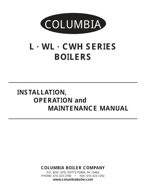
COLUMBIAL • <strong>WL</strong> • CWH SERIESBOILERSINSTALLATION,OPERATION andMAINTENANCE MANUALCOLUMBIA BOILER COMPANYP.O. BOX 1070, POTTSTOWN, PA 19464PHONE: 610-323-2700 • FAX: 610-323-7292www.columbiaboiler.com
Table Of ContentsPARTS WARRANTY . . . . . . . . . . . . . . . . . . . . . . . . . . . . . . . . . . . . . . . . . . . . . . . . . . . . . . . . . . . . .2INTRODUCTION . . . . . . . . . . . . . . . . . . . . . . . . . . . . . . . . . . . . . . . . . . . . . . . . . . . . . . . . . . . . . . .3SERVICE POLICY . . . . . . . . . . . . . . . . . . . . . . . . . . . . . . . . . . . . . . . . . . . . . . . . . . . . . . . . . . . . . .4INSTALLATION . . . . . . . . . . . . . . . . . . . . . . . . . . . . . . . . . . . . . . . . . . . . . . . . . . . . . . . . . . . . . . . . .5BOILER ROOM . . . . . . . . . . . . . . . . . . . . . . . . . . . . . . . . . . . . . . . . . . . . . . . . . . . . . . . . . . .5VENTING . . . . . . . . . . . . . . . . . . . . . . . . . . . . . . . . . . . . . . . . . . . . . . . . . . . . . . . . . . . . . . . .5JACKET ASSEMBLY . . . . . . . . . . . . . . . . . . . . . . . . . . . . . . . . . . . . . . . . . . . . . . . . . . . . . . .6BURNER MOUNTING . . . . . . . . . . . . . . . . . . . . . . . . . . . . . . . . . . . . . . . . . . . . . . . . . . . . . .7BOILER CONNECTIONS . . . . . . . . . . . . . . . . . . . . . . . . . . . . . . . . . . . . . . . . . . . . . . . . . . .8FUEL CONNECTIONS . . . . . . . . . . . . . . . . . . . . . . . . . . . . . . . . . . . . . . . . . . . . . . . . . . . .11CLEANING AND FILLING A NEW STEAM BOILER . . . . . . . . . . . . . . . . . . . . . . . . . . . . . . . . . . .16OPERATING THE BOILER . . . . . . . . . . . . . . . . . . . . . . . . . . . . . . . . . . . . . . . . . . . . . . . . . . . . . . .18STARTING THE BOILER . . . . . . . . . . . . . . . . . . . . . . . . . . . . . . . . . . . . . . . . . . . . . . . . . .19STOPPING THE BOILER . . . . . . . . . . . . . . . . . . . . . . . . . . . . . . . . . . . . . . . . . . . . . . . . . 19BURNER START UP AND TEST INFORMATION . . . . . . . . . . . . . . . . . . . . . . . . . . . . . . . . 20CONTROL DESCRIPTIONS . . . . . . . . . . . . . . . . . . . . . . . . . . . . . . . . . . . . . . . . . . . . . . . . 21MAINTENANCE . . . . . . . . . . . . . . . . . . . . . . . . . . . . . . . . . . . . . . . . . . . . . . . . . . . . . . . . . . . . . . 24Daily Boiler Check & Maintenance List . . . . . . . . . . . . . . . . . . . . . . . . . . . . . . . . . . . . . . . 24Monthly Boiler Check & Maintenance List . . . . . . . . . . . . . . . . . . . . . . . . . . . . . . . . . . . . 25Semiannual Boiler Check & Maintenance List . . . . . . . . . . . . . . . . . . . . . . . . . . . . . . . . . . 25Annual Boiler Check & Maintenance List . . . . . . . . . . . . . . . . . . . . . . . . . . . . . . . . . . . . . .25WATER TREATMENT . . . . . . . . . . . . . . . . . . . . . . . . . . . . . . . . . . . . . . . . . . . . . . . . . . . . . . . . . . .27APPENDICES . . . . . . . . . . . . . . . . . . . . . . . . . . . . . . . . . . . . . . . . . . . . . . . . . . . . . . . . . . . . . . . . .30Recirculation; Twin Units and Tank SystemsSpecifications and Data - L <strong>Series</strong>; <strong>WL</strong> <strong>Series</strong>; CWH <strong>Series</strong>Replacement Parts List for L, <strong>WL</strong> & CWH <strong>Series</strong> BoilersBurks Turbine Pumps - Impeller Adjustment InstructionsPiping Layout Dwgs. PL-100, PL-101, PL-099, PL-102Corning Tubular Gage Glasses, Red Line - Use, Care and InstallationWarrick Probe <strong>Series</strong> 26 ControlsWarrick Probe Assembly - Replacement PartsSafety Valve Piping, TypicalMcDonnell & Miller Installation & Maintenance Instructions (one or more):MM-201(B) <strong>Series</strong> 767 Low Water Cut-Offs for Steam BoilersMM-213(C) <strong>Series</strong> 750 Probe Type Low Water Cut-Offs with Remote SensorsMM-231 <strong>Series</strong> 42 Low Water Cut-Off/Pump ControllerMM-316 <strong>Series</strong> 247-2 Combination Mechanical Water Feeder/Low Water Cut-OffPressure Control Bulletin (steam units only)Honeywell Aquastat Controllers L4006 IOM Bulletin
IMPORTANT1. Read and familiarize yourself with this installation, operation, andmaintenance manual before installing, operating, or servicing yourboiler.2. All cover plates, enclosures, and safety devices must be installedat all times except while performing maintenance and service.3. Only trained service technicians should do any work on yourboiler.4. All state and local codes take precedence over anyrecommendations given in this manual.L<strong>WL</strong>CWH COLUMBIA BOILER COMPANY REV. 31071
LIMITED PARTS WARRANTYThe <strong>Columbia</strong> Boiler Company (hereinafter <strong>Columbia</strong>) warrants the burner componentsand controls installed on its boiler/burner units to be free from defects in materialand workmanship under normal use and service for 12 months from the date ofinstallation or 18 months from the date of manufacture, whichever date occurs first andis subject to warranty approval by the manufacturer of the specific components. Thiswarranty does not extend to equipment subjected to misuse, neglect, accident orimproper installation. Equipment which is defective in material or workmanship and isremoved within 12 months from the date of installation will be repaired or replaced asfollows:(a) Motors, fuel units, controls, and transformers should be sent for repair orreplacement to an authorized service point or distributor of the manufacturer ofsuch component when reasonably available in Customer’s locality.(b) Where such local service is not available with respect to the above listed components,or where other components are involved, such defective equipmentshould be returned after receiving authorization from your dealer, freight prepaid,to the <strong>Columbia</strong> Boiler Co., 390 Old Reading Pike, Pottstown PA 19464.The use of the <strong>Columbia</strong> returned goods form is mandatory when returningdefective material.(c) <strong>Columbia</strong> is not responsible for any labor cost for the removal and replacementof equipment.(d) Equipment which is repaired or replaced will carry a warranty equal to the unexpiredportion of the original equipment warranty.(e) If inspection by <strong>Columbia</strong> does not disclose any defect covered by this warranty,the equipment will be repaired or replaced at the expense of the Customer,and <strong>Columbia</strong>’s regular charges will apply.THIS WARRANTY IS LIMITED TO THE PRECISE TERMS SET FORTHABOVE, AND PROVIDES EXCLUSIVE REMEDIES EXPRESSLY IN LIEU OFALL OTHER REMEDIES. ALL IMPLIED WARRANTIES, INCLUDING BUTNOT LIMITED TO ANY IMPLIED WARRANTY OF MERCHANTABILITY ORFITNESS FOR A PARTICULAR PURPOSE OR USE, ARE EXCLUDED. IN NOEVENT WILL COLUMBIA BOILER CO. BE LIABLE FOR ANY INCIDENTALOR CONSEQUENTIAL DAMAGES OF ANY NATURE. <strong>Columbia</strong> neither assumesnor authorizes any person to assume for <strong>Columbia</strong> any other liability or obligation inconnections with the sale of this equipment. <strong>Columbia</strong>’s liability and Customer’s exclusiveremedy being limited to repairs or replacement as set forth above.March 10, 1997L<strong>WL</strong>CWH COLUMBIA BOILER COMPANY REV. 131062
INTRODUCTION<strong>Series</strong> L and <strong>WL</strong> Water Tube BoilersThe <strong>Columbia</strong> Models L and <strong>WL</strong> are water tube boilers designed for hot water, and/or low pressuresteam applications. These units are manufactured to the specifications set forth by Section IV of theASME Boiler and Pressure Vessel Code. Boilers are inspected and stamped for conformity to requirementsof the National Board of Boiler and Pressure Vessel Inspectors. All boilers are designed to befired using No. 2 fuel oil, and/or natural, manufactured, or liquid propane (LP) gas, and are poweredby standard AC electrical service.CWH <strong>Series</strong> Steam BoilerThe CWH <strong>Series</strong> is a steam boiler used for indirect hot water applications. This boiler classificationconsists of all L and <strong>WL</strong> <strong>Series</strong> Boilers providing heat transfer to one or two coils, depending on boilersize. The boiler is a self contained unit allowing a steam cavity above the water line for expansion.<strong>Columbia</strong> hot water and low pressure steam boilers are typically shipped knocked down (unassembled),but are also available factory packaged. All boilers are furnished with a jacket kit, burner, andboiler trim. Boiler trim consists of the operating and limit controls, pump and/or low water cut off(LWCO) controls, a safety valve, and a smokehood for all <strong>WL</strong> <strong>Series</strong> Boiler Models, and Model L-32.Factory packaged boilers are fully assembled and test fired.L<strong>WL</strong>CWH COLUMBIA BOILER COMPANY REV. 131063
SERVICE POLICYAnything mechanical will inevitably need servicing. Steam and hot water boilers areroutinely serviced by the installer or another boiler maintenance company. Occasionallythe service technician may be unable to determine the cause of the problem. In this situation,the dealer or service organization should contact the selling distributor for help.Should the problem persist, the distributor will contact the sales representative forassistance. Depending on the extent of the problem, the representative may requesttechnical assistance from the factory.If the problem cannot be resolved by the representative, he should contact theTechnical Service/Engineering Department at the factory. The sales representative willneed the following information. It is essential that this information be available to assureprompt service.Boiler Model and Size (HP)_____________________________________________________Boiler Serial Number __________________________________________________________Boiler National Board Number _________________________________________________Date Installed ________________________________________________________________Burner Type and Model ________________________________________________________Primary Burner Control Type ______________________________________________Installer’s Name ______________________________ Phone (____)____________________Address ____________________________________________________________________Distributors Name ___________________________ Phone (____)_____________________Address _____________________________________________________________________Sales Representative _________________________ Phone (____)_____________________Address ____________________________________________________________________Specific Problem - DetailedL<strong>WL</strong>CWH COLUMBIA BOILER COMPANY REV. 131064
INSTALLATIONBEFORE BEGINNING INSTALLATION, CAREFULLY STUDY THESEINSTRUCTIONS AND ALL CHARTS, DRAWINGS, AND DIAGRAMSSHIPPED WITH THE BOILER.Installation must follow all state and local code requirements, Fire and Underwriters regulations, andstandard plumbing practices. The electrical installation shall be in accordance with the NationalElectrical Code.Remove all boiler components from packaging and inspect prior to assembly to ensure that damagehas not occurred in shipping.BOILER ROOMLocate the boiler in a well lit area on a noncombustible, level floor. Make available a convenient watersupply and allow adequate drainage, including unobstructed floor drains, for flushing and filling theboiler. Provide sufficient make-up air for combustion at all times. Power the boiler using a properlyrated electrical service. Include fused disconnects for control circuits, blower motor circuits, and feedpump circuits that require a motor contactor or motor starter relay.Where possible, place the boiler on a 3 inch concrete pad. Allow adequate clearance between theboiler and any walls or obstructions to permit inspection and service on burner, boiler piping, controls,or combustion vent.DO NOT install exhaust fans in or near the boiler room. Exhaust fans steal available make-up air duringburner operation; and more importantly, when the boiler cycles off, exhaust fans pull hot fluegases back through the burner causing burner parts to deteriorate, and to eventually fail prematurely.Maintain a positive pressure in the boiler room at all times.Do not allow your boiler room to become a storage room.VENTINGAll <strong>Columbia</strong> boiler models utilize a pressure fired burner and need only to be properly vented. Forsituations where unusual conditions may exist, consult the factory for proper venting.Locate the boiler as close as possible to the chimney or other approved exhaust vent. For boiler modelswith a rectangular flue outlet, first bolt the supplied smokehood in place. Attach all flue piping tothe round flue connection and make each connection secure. The flue pipe should not be insertedbeyond the inside wall of the chimney.DO NOT REDUCE THE SIZE OF THE FLUE OUTLET OR FLUE PIPING.<strong>Columbia</strong> Boiler recommends the use of galvanized B Type vent for stack connections suitable fortemperatures to 550F. The flue pipe should be pitched upward at least 1/4” per foot of run. Avoid theuse of tees, sharp bends, and long horizontal runs. Install a draft regulator if required.L<strong>WL</strong>CWH COLUMBIA BOILER COMPANY REV. 131065
COLUMBIA BOILER COMPANY OF POTTSTOWN SHALL NOT BE HELD LIABLE FOR DAMAGETO THE BOILER CAUSED BY INCORRECT VENT CONDITIONS AND/OR INSUFFICIENT BURN-ER MAKEUP AIR.JACKET ASSEMBLYAssemble the jacket kit around the boiler as shown in Figure 1. Place each panel against its respectiveside of the boiler.NOTE:The side panels for boiler Models <strong>WL</strong>-120, <strong>WL</strong>-140 and <strong>WL</strong>-180 are two piece sidewalls. Assemble these side wall pieces together before proceeding with jacketinstallation.Assemble the lower front panel to one side wall at a time. Next, attach the lower rear panel to eachside wall of the boiler. When applicable, mount the upper front and rear panels in their respectivelocations. Attach the joiner plate behind the lower portion of the lower front panel as shown. Finally,assemble the top right and left jacket panels on top of the boiler. Attach these panels to the previouslyassembled jacket components. If necessary, prepipe the top of the boiler before assembling thetop jacket panels. The top jacket panels are designed to allow prepiping to the top center boiler fittings,if needed.Figure 1L<strong>WL</strong>CWH COLUMBIA BOILER COMPANY REV. 131066
BURNER MOUNTINGIf the burner is to be installed on site, first apply a gasketing material between the burner flange andthe burner mounting plate to seal the burner. Use a non-asbestos fiber rope, or a wet insulating materialfor a gasket, as shown in Figure 2. Wet insulation is the preferred gasketing material because itcompresses into a flat gasket which conforms to and fills any and all voids. Secure the burner in theboiler using the four bolts supplied with the burner. See the Burner Section of this manual for properelectrical wiring, and fuel supply piping.Note: All factory packaged boilers use a wet insulation material as a gasket.Figure 2L<strong>WL</strong>CWH COLUMBIA BOILER COMPANY REV. 131067
BOILER CONNECTIONSDrainsAll <strong>Columbia</strong> Boiler units have (4) washouts located around the lower corners of the boiler for drainagepurposes. Install a pipe nipple and ball valve in a least one washout for use as a drain. If a washoutis not needed, plug it by using the proper size nipple and a pipe cap. DO NOT use a pipe plug.Low Water Cut-OffsAll <strong>Columbia</strong> boilers are supplied with a single low water cut-off (LWCO) as standard equipment.Several boiler applications may require a secondary LWCO. The standard equipment is as follows:Hot Water Boilers - McDonnell & Miller 750-MT-120 Probe Type Low Water Cut-Off with RemoteSensor - Thread the Remote Sensor into the 3/4” NPT fitting located on top of the boiler. Mount theControl Box near the top of the front jacket panel (or upper front jacket panel on some units).Steam Boilers - McDonnell & Miller Model 767 Quick-Hook-Up Low Water Cut-Off - Install this deviceinto the 2-1/2” NPT welded coupling found on the coil plate for L <strong>Series</strong> boilers, and on the left handside of the heat exchanger for <strong>WL</strong> <strong>Series</strong> boilers.Water Heaters - McDonnell & Miller Model 767 Quick-Hook-Up Low Water Cut-Off - Install this deviceinto the 2-1/2” NPT welded coupling found on the coil plate for CWH-170 / -610 <strong>Series</strong> boilers, andon the left hand side of the heat exchanger for CWH-780 / -2460 <strong>Series</strong> boilers.Secondary Low Water Cut-OffsSecondary LWCO s may be required to meet local codes or CSD-1 requirements. A Warrick 26C1C1CProbe Type Low Water Cut-Off is used in steam applications to meet CSD-1 requirements. Thread theremote sensor into the 1/2" NPT fitting located on top of the boiler using a 1/2" x 3/8" bushing. SeeTable 1. for proper probe rod length. Mount the control box to a front or side jacket panel on theboiler.LENGTH OF PROBE ROD IN “L” AND UP TO” CWH-610” SERIES BOILERSBOILER L-18 L-20 L-22 L-24 L-30 L-32MODEL CWH-170 CWH-240 CWH-300 CWH-390 CWH-475 CWH-610ROD LENGTH 4-7/8" 6-1/4" 6-1/4" 6-1/4" 7" 9-5/8"Table 1aL<strong>WL</strong>CWH COLUMBIA BOILER COMPANY REV. 131068
LENGTH OF PROBE ROD IN “<strong>WL</strong>” AND UP TO” CWH-780 & UP” SERIES BOILERSBOILER <strong>WL</strong>-60 <strong>WL</strong>-90 <strong>WL</strong>-120 <strong>WL</strong>-140 <strong>WL</strong>-180MODEL CWH-780 CWH-1200 CWH-1510 CWH-1810 CWH-2460ROD LENGTH 14-1/2" 14-1/2" 14-1/2" 14-1/2" 14-1/2"Table 1bOther secondary LWCO s include combination LWCO / Water Feeders. These devices are typicallyconnected externally using an equalizing line, and piped into the available 1" NPT fittings found inboiler top, and left side or front. Most commonly used combination units are McDonnell & Miller 42<strong>Series</strong> Pump Controls and Low Water Cut-Off or McDonnell & Miller No. 247-2 Feeder Combination.For piping diagram, see the List of Figures on the Table of Contents Page of this manual.NOTE: Mount a combination unit so the low water cut-off line on the device is approximately 3inches above the lowest permissible water level plate found on the left side jacket panel ofhe boiler.Water GaugeThe water gauge is piped into the (2) 1/2" NPT fittings located in the left side of the boiler. During operation,the boiler s water level should always be above the Lowest Permissible Water Level indicatorlabel found on the left side jacket panel of the boiler. Hot water boilers do not require a Water Gauge.Pressure ControlsLow pressure, 15 PSI controls are supplied with steam units only. These controls consist of anOperating Control and a Safety Limit. An additional operating control may also be supplied for burnersthat function with low-high-low operation. Pipe the Pressure Control and the 30 PSI Steam Gaugeusing the supplied steam syphons. See Drawing PL-099 in the Appendix.The Pressure Control must be level in order to operate accurately. A Pressure Control is level whenthe leveling indicator hangs freely with its pointer directly over the index mark, inside the back coverof the case.Aquastat Controllers ®Aquastat Controllers are used to regulate boiler water temperature. <strong>Columbia</strong> supplies an OperatingControl (Honeywell L4006A Aquastat ® ) and a Safety Limit (Honeywell L4006E Aquastat ® ) with all hotwater boilers and water heaters. An additional Operating Aquastat ® may also be supplied for burnersthat function with low-high-low operation or steam boilers using an optional coil. Aquastat ® ’s aremounted in the 3/4" NPT fittings located on the coil plate on the front of the boiler.L<strong>WL</strong>CWH COLUMBIA BOILER COMPANY REV. 131069
Safety Valve / Relief ValveAll safety or relief valves are located in the rear center fitting on top of the boiler. A 15 PSI SteamSafety Valve is supplied for steam boiler and water heater applications. A 30 PSI Water Relief Valve isused for hot water applications. All safety and relief valves should be safely piped away from the boilerwithout reducing the valve s outlet port size.Steam SupplyPipe the steam lines to the largest fitting or flange located on top of the boiler.Note: For CWH UNITS ONLY - Plug the main steam outlet unless an expansion tank is used.Hot Water SupplyUse the fitting/pipe flange on the top of the boiler for the hot water supply to the system. Hot waterapplications also require the use of an expansion tank in the supply piping, to compensate for fluctuationsin the water volume during heating and cooling cycles.Feed Water SupplyVirtually any unused port on the heat exchanger can be used for the feed water supply, including anyunused drain port. In situations where make up water is needed, the water supply must be treatedbefore it enters the boiler, to prevent the formation of scale, or to protect the boiler surfaces from thecorrosive effects of oxygenated water. Water treatment and a water treatment program must be practiced,or the life of the boiler will be severely limited. If a Condensate Return / Feedwater Tank is used,connect the feedwater source to the float valve on the tank.CoilsBoilers are shipped with the coil(s) assembled to the coil plate(s), and mounted in the boiler. For thesmaller L-<strong>Series</strong>, L-18(CWH-170) thru L-24(CWH-390), the coil plates cover the opening for which thecoils pass through. The indirect water inlet and outlet connections are made in the rear of the boiler.All other <strong>Columbia</strong> models can be furnished with one or two coils. CWH models larger than a CWH-390 always have two coils.When making coil connections for twin coil units, manifold indirect water piping using copper tubingand fittings connected in parallel. Pipe the outside coil openings together for cold water inlets, andthe inside coil openings for hot water outlets. If necessary, temper the hot water supply by using amixing valve. Connect the hot water outlet source and a cold water supply line to a mixing valve, totemper the hot water supply to the proper temperature requirements for process equipment.Whenever boilers are supplied with one or two coils, the coils must be covered by a minimum of twoinches of water, during normal operation, to allow proper heat transfer through the coil. Adjust allLWCO piping to keep the coil(s) submerged in the event of a low water situation.L<strong>WL</strong>CWH COLUMBIA BOILER COMPANY REV. 1310610
FUEL CONNECTIONSOIL SUPPLY PIPINGConnect burner to oil supply. Refer to fuel unit manufacturer literature for piping, connections, lift andtank installation. If such information is unavailable use the following guidelines:Fuel supply “level with” or “above” burner: A single stage fuel unit connected to the fuel supplywith a single supply line is the most common type of installation for these conditions. <strong>Manual</strong> ventingof the fuel oil is usually required on initial start up. Failure to vent air could result in air lock/oil starvation.(OnePipe)Fuel supply below the level of the burner: Use a single stage fuel pump in lift conditions of up to10 feet and a two stage pump when lift exceeds 10 feet. Both conditions require the use of a returnline which purges the fuel pump of air, returning it to the fuel tank. The by-pass plug must be insertedinto the fuel pump when installing a return line.(Two Pipe)Fuel line installation: Consult the burner section of this manual for oil line type and sizing requirementsfor proper operation. The size of oil lines is extremely important for proper operation.Continuous lengths of heavy wall copper tubing are recommended and should be installed under thefloor whenever possible. Fuel lines should not chaff the appliance or building structure.All oil feed lines must be air tight. Use as few fittings as possible when assembling the oil lines.Compression fittings allow more of a chance for air to be introduced into the oil supply. The slightestair leak, usually caused by loose fittings or bad gaskets, can cause poor starts, smoky starts, sootingof burner parts, inefficient operation, and a dangerous combustion condition. Always install fittingsin accessible locations.WARNING:TEFLON ® TAPE SHOULD NEVER BE USED WITH ANY OIL LINE CONNECTIONS.THE USE OF TEFLON ® TAPE ON BURNER COMPONENTS OR OIL SERVICE LINESWILL VOID MOST BURNER WARRANTIES.A vacuum test should be done on all installations to ensure that all fittings are tight and the oil linesare of proper size. Suction vacuums must be held to acceptable limits.Fuel line valve and filter: (Not supplied) Install two high quality shutoff valves in accessible locationson the oil supply line. Locate one close to the tank and the other close to the burner ahead of the filter.Some filters come with built-in shutoff valves. Install a generous capacity filter inside the buildingbetween the fuel tank shutoff and burner.For additional information consult the burner section of this manual.L<strong>WL</strong>CWH COLUMBIA BOILER COMPANY REV. 1310611
GAS SUPPLY PIPINGContact your local gas company to ensure that adequate gas service is available, and to review applicableinstallation codes for your area.The minimum gas supply pressure required by the burner is five inches water column for the GL-18,GL-20, GL-22, GL-24, CWH-170, CWH-240, CWH-300, CWH-390 and seven inches water column forthe GL-30, GL-32, CWH-470, CWH-610, CWH-780, CWH-1200 CWH-1510, CWH-1810, CWH-2460and all <strong>WL</strong> <strong>Series</strong> boilers. The maximum gas supply pressure to the burner is fourteen inches watercolumn. Gas pressure greater than fourteen inches water column will require an additional gas pressureregulator to prevent damage to the primary gas regulator. Gas pressure below the minimum willcause combustion efficiency problems and should be avoided if possible. Low gas pressure may alsoprevent the boiler from obtaining the desired input rate, which will cause the boiler to be unable toproduce the desired output. Consult the factory if your gas supply pressure is not in the recommendedrange.Use the following tables to determine the size of the main gas line required for the boiler that is beinginstalled. First determine the required input volume of gas needed at the gas manifold, then determinethe correct pipe size for the length of run needed.L<strong>WL</strong>CWH COLUMBIA BOILER COMPANY REV. 1310612
REQUIRED INPUT - CUBIC FEET OF GAS PER HOURGAS TYPEL-18 L-20 L-22 L-24 L-30 L-32CWH-170 CWH-240 CWH-300 CWH-390 CWH-475 CWH-610NATURAL 168 252 336 420 560 700PROPANE 67 101 134 168 224 280GAS TYPE<strong>WL</strong>-60 <strong>WL</strong>-90 <strong>WL</strong>-120 <strong>WL</strong>-140 <strong>WL</strong>-180CWH-780 CWH-1200 CWH-1510 CWH-1810 CWH-2460ROD LENGTH 840 1260 1680 1960 2520PROPANE 336 504 672 784 1008CAPACITY OF PIPE - CUBIC FEET OF GAS PER HOUR AT 0.2" W.C. PRESSURE DROPEquivalentLength (ft)1" 1-1/4" 1-1/2" 2" 2-1/2" 3" 4"10 425 725 1170 2360 4300 6250 1280020 300 520 800 1700 3000 4500 930030 250 425 690 1400 2500 3750 750040 210 360 560 1200 2100 3200 640050 190 325 500 1100 1900 2850 580060 180 300 480 1000 1800 2300 480080 150 260 410 850 1550 2000 4200100 135 230 370 750 1375 1680 3500150 110 190 300 600 1100 1200 2750200 75 165 260 540 950 1000 2000FittingEquivalent Lengths of Standard Pipe in Feet for Listed FittingsStd. Tee 5.5 7.5 9.0 12.0 13.5 15 20Std. Elbow 2.7 3.7 4.5 5.5 6.1 8 11Vent lines, if required, are to be run outside the building, stopping clear of windows or fresh air intakes.The vent should terminate in a way that will not allow the possibility of water, dirt, insects, animals,and other matter from entering and clogging the vent pipe.L<strong>WL</strong>CWH COLUMBIA BOILER COMPANY REV. 1310613
Gas lines should be tested for leaks. Your gas company may wish to witness this test. Do not exceedthe maximum pressures allowed by the valve train.Additional gas piping information is included in the burner section of this manual.COMBUSTION AIRIt is essential that provisions are made for a fresh supply of outside air into the boiler room to insurecomplete combustion, proper boiler efficiency, and a clean fire. Sufficient makeup air also helps preventnuisance shut-downs due to excessive combustion byproduct build-up on burner parts. Outsideair may be provided through ducts, fixed louvers or motorized louvers.A rule of thumb for calculating fresh air openings to the outside is 63 sq. in. for every 100,000 BTUHgross output, or 21 sq. in. per boiler horsepower. The result of the above calculation is expressed asfree area, meaning no restrictions of any kind. If louvers or screens are used over combustion airopenings, calculate the percentage of free area to allow for these restrictions.Do not have exhaust fans in the immediate proximity of the boiler room if at all possible, as they willcause a reversal of draft through the boiler when the burner is cycled off. This draft reversal drawsheat from the combustion chamber back through the burner. This heat will deteriorate burner componentsprematurely, and eventually, burner operation will fail. The boiler room should experience apositive pressure when the burner is not firing.In situations where a boiler room experiences a negative pressure, use a direct air intake. A direct airintake uses an adapter over the burner fan intake housing to draw in outside air through duct work,from an external source. Consult burner manufacturer for parts and availability.Important Note: Surface discoloration of the building mayoccur due to improper boiler/burner adjustment and maintenance.<strong>Columbia</strong> Boiler Company will not accept any liabilityfor such discoloration.L<strong>WL</strong>CWH COLUMBIA BOILER COMPANY REV. 1310614
REQUIRED BOILER MAKE-UP AIRBOILER SIZE(HORSEPOWER)L-18CWH-170L-20CWH-240L-22CWH-300L-24CWH-390L-30CWH-475L-32CWH-610L-60CWH-780L-90CWH-1200L-120CWH-1510L-140CWH-1810L-180CWH-2460OPENING SQUARE HOLE ROUND PIPEBTU INPUT MIN. SQUARE SIZE - INCHES SIZE - INCHESINCHES (APPROXIMATE) (APPROXIMATE)196,000 84 10 X 10 1280,000 126 12 X 12 14336,000 168 14 X 14 16420,000 210 15 X 15 18560,000 273 17 X 17 20700,000 336 19 X 19 22840,000 420 21 X 21 241,260,000 630 26 X 26 301,680,000 840 30 X 30 341,960,000 987 32 X 32 362,520,000 1260 36 X 36 38L<strong>WL</strong>CWH COLUMBIA BOILER COMPANY REV. 1310615
CLEANING AND FILLING A NEW STEAM BOILERNote:The following procedure is for steam boilers only. This procedure should also be usedfor indirect water boilers (CWH-<strong>Series</strong>).In order to minimize the corrosive effects of raw water oxidation on the boiler, the water must beheated to at least 180°F immediately after entering the boiler, in order to drive off the corrosivedissolved gases. This applies to all water - whether from a well, a spring, or from the local municipalwater system.The oil and grease that accumulate in a new steam boiler can usually be washed out by boiling asfollows:1. Fill the boiler to the normal waterline.2. Remove the safety valve.3. Provide a boil-out compound of caustic soda and trisodium phosphate in theproportions of 2-1/2 lbs. of each chemical per 120 gallons of water.CAUTION:USE CARE IN HANDLING THESE CHEMICALS. THE CAUSTIC SODA ISEXTREMELY CORROSIVE TO SKIN AND CLOTHING. DO NOT PERMIT EITHERTHE DRY MATERIAL OR THE CONCENTRATED SOLUTION TO CONTACT SKINOR CLOTHING.BOILER MODELEQUAL AMOUNTSCAUSTIC SODA ANDTRISODIUM PHOSPHATEL-18 / CWH-1708 8 ozL-20 / CWH-240 10 1/3 ozL-22 / CWH-300 14 1/3 ozL-24 / CWH-390 1 lb 2 1/3 ozL-30 / CWH-475 1 lb 10 2/3 ozL-32 / CWH-610 1 lb 14 oz<strong>WL</strong>-60 / CWH-780<strong>WL</strong>-90 / CWH-1200<strong>WL</strong>-120 / CWH-1510<strong>WL</strong>-140 / CWH-1810<strong>WL</strong>-180 / CWH-24602 lb 12 1/3 oz3 lb 3 1/3 oz4 lb 1/3 oz4 lb 7 1/3 oz6 lbL<strong>WL</strong>CWH COLUMBIA BOILER COMPANY REV. 1310616
4. Mix the chemicals with water and pour into the boiler through the safety valve opening.5. Replace the safety valve.6. Start the firing equipment.7. Boil the water for at least five hours.8. Stop the firing equipment.9. Drain the boiler to a location where hot water can be discharged safely.10. Wash the boiler thoroughly using a hose with sufficient pressure.11. Fill the boiler to the normal waterline.12. Add boiler water treatment as prescribed by a water treatment specialist.13. Boil or bring water temperature to at least 180°F immediately.14. The boiler is ready to put into service or on standby.L<strong>WL</strong>CWH COLUMBIA BOILER COMPANY REV. 1310617
OPERATING THE BOILERNOTE:Although each factory packaged unit has been test fired at the factory, each boilermust be “set up” for the conditions on location. Improper combustion settings maycause the burner to operate erratically, resulting in boiler shutdowns, lost time, andunnecessary service expenses.PRE-START CHECKS AND INFORMATIONA new or relocated boiler should not be put into service until it has been inspected by an authorizedinspector for the jurisdiction or the insurance company, and the required certificates have beenissued.Whenever a new boiler is placed in service, operating data should be recorded and saved for futurereference. This information is extremely valuable for diagnosing problems if abnormal operationoccurs. Record all operating parameters such as pressures, stack temperatures, oxygen or carbondioxide levels, flows, draft, motor amps, damper positions, and interlock set points. A burner start upand test information sheet has been included at the end of this section for your convenience.All cover plates, enclosures, and safety devices must be installed at all times except while performingmaintenance and service.The fuel supply should not be turned on until the combustion chamber has been vented and the pilotlight (if gas ignited) checked for proper operation.All drain valves including blowdown valves for stream boilers, water column drain valves, gauge glassdrain valves, and gauge cocks, should be closed.The safety/relief valves should be inspected externally to see that they are free to operate, and thatthe discharge piping and drain piping are open to the atmosphere, and free to expand without imposinga load on the safety valve bodies. Make sure the safety valve is piped to a safe location to preventinjury.The boiler feed pump(s) for steam applications should be checked to ensure that they are ready forservice. Check the data on rating plates of all electrical equipment to be certain the electrical characteristicsmatch those of the electric supply to which they are connected.Before attempting start-up, carefully study the instructions included in the burner section of thismanual.It is important to have the proper test equipment in order to adjust the combustion and pilot ifequipped. Those items that may be required include a manometer, micro ammeter, vacuum gauge, 0-300 PSI pressure gauge, carbon dioxide or oxygen analyzer, carbon monoxide tester, smoke gun, andstack thermometer.L<strong>WL</strong>CWH COLUMBIA BOILER COMPANY REV. 1310618
STARTING THE BOILERWARNING:NEVER OPERATE A BOILER WITHOUT BEING SURE IT IS FILLED WITH WATERAND THAT PROPER WATER TREATMENT CHEMICALS HAVE BEEN ADDED.Allow the boiler to fill with water to its normal operating level.Supply power to the boiler disconnects.NOTE:NOTE:The burner will not operate when the boiler has reached its normal water level, until thereset button on the manually reset, probe type, low water cut-off is pushed.Combustion efficiency must be checked at this time. See the burner manufacturersinstructions for correct settings and more detailed information.Follow the adjustment procedures outlined in the burner section of this manual to set up the burnerfor proper operation.STOPPING THE BOILERTo stop the boiler turn the main disconnect to the OFF position.L<strong>WL</strong>CWH COLUMBIA BOILER COMPANY REV. 1310619
BURNER START UP AND TEST INFORMATIONFor a new boiler start up, or for troubleshooting an existing installation, the followinginformation is essential for effective service assistance.Boiler Model_________________ Serial No.________________ N.B. No.______________________Burner Model________________ Invoice No._______________ Serial No._____________________Installation Name__________________________________________ Start Up Date_________________Start Up Contractor________________________________________ Phone No.____________________Name of Technician Performing Start Up_____________________________________________________Fuel Type: ❑ Natural Gas ❑ LP Gas ❑ Fuel Oil (#2) ❑ Other_________________________________Gas FiringGas Pressure At Train Inlet Flame Signal Readings Stack Outlet Test Point DraftBurner In Off Position_______ "W.C. Pilot____________________________ High Fire__________________ "W.C.Gas Pressure At Train Inlet CO2 Over Fire DraftHigh Fire__________________ "W.C. High Fire_________________________ High Fire__________________ "W.C.Gas Pressure At Main Orifice CO Net Stack TemperatureHigh Fire__________________ "W.C. High Fire_________________________ High Fire___________________°FGas Pressure At Pilot Orifice__________________ W.C.Measured Input Rate - BTU/HRHigh Fire__________________ "W.C.Oil FiringHigh Fire Vacuum Reading At Oil CO2 Stack Outlet Test Point DraftPump Inlet_______________ "H.G. Low Fire________________________ Low Fire__________________ "W.C.High Fire_________________________ High Fire__________________ "W.C.Oil Nozzle Supply Pressure Bachrach Scale Smoke Number Net Stack TemperatureLow Fire__________________PSI Low Fire_________________________ Low Fire___________________°FHigh Fire__________________PSI High Fire_________________________ High Fire___________________°FFiring Rate - GPHLow Fire__________________High Fire__________________Over Fire DraftLow Fire___________________ "W.C.High Fire___________________ "W.C.Operational Check of ControlsOperating Limit__________________❑ Aux LWCO______________________❑ Flame Safeguard________________❑Safety Limit_____________________❑ Low Gas Pressure_______________❑ Ignition Failure ❑Low Water Cut Off_______________❑ High Gas Pressure_______________❑ Flame Failure ❑Comments___________________________________________________________________________________________________________________________________________________________________________________________________________________________________________________________________________________________________________________________________________________________________________________________________________________________________________________________________________________________________________________________________________________________________________________________________________________________________________________________________L<strong>WL</strong>CWH COLUMBIA BOILER COMPANY REV. 1310620
CONTROL DESCRIPTIONSSTEAM BOILERSPressure ControlsAll <strong>Columbia</strong> steam boilers are controlled by both operating and safety limit Pressure Control. Bothdevices are adjustable and use pressure actuated mercury switches. These switches open whenpressure reaches the main scale set point value, cycling the boiler off.The operating Pressure Control also has an adjustable differential feature. Differential settings valuesare subtractive from the main scale set point value, indicating the change in pressure for when theboiler will refire. Always adjust the differential set point above the required steam pressure for the system.Make the differential value as large as possible to prevent short cycling.The safety limit Pressure Control does not have an adjustable differential, and has a manual reset feature.The safety limit Pressure Control breaks the control circuit if the operating Pressure Controlbecomes inoperable, and steam pressure continues to climb. The burner will not start until the excessivepressure situation is corrected and the reset button is pushed.Adjust the safety limit value higher than the operating limit under normal operating conditions. Thissetup allows the operating control to function properly and reduces the need to reset the control circuitconstantly. Set the safety limit value less than the error margin of the safety relief valve, so thePressure Control can safely control boiler pressure.Make set point value adjustments by turning the adjusting screws found on top of the PressureControl casing.For additional information on either Pressure Control, see the Danfoss Publication following this booklet.Low Water Cut-offsLow water cut-offs safely control boiler operation in the event of a low water condition. The standardLWCO for steam applications is a McDonnell & Miller #767. If an installation needs a CSD-1 requirement,an additional Warrick 26C1C1C probe type LWCO is supplied. Other optional equipment usedin place of, or in addition to, one of the aforementioned LWCO s includes water feeders and combinationLWCO/ feeders.The McDonnell & Miller #767 is a float operated control consisting of a large sediment chamber withits own spring closing blow-off valve. The float actuated low water switch opens in a low water condition.In the same instance, the McDonnell & Miller #767 has an extra set of contacts that close witha drop in water level. If necessary, this set of contacts could be used to activate an additional waterfeeder.A Warrick 26C1C1C “Probe” type LWCO is used only as a Secondary low water cut-off device. Itsprimary function is to protect the boiler against low water situations where the primary LWCO fails tobreak the control circuit. The probe mounts in the top head of the boiler and has a rod length lowerL<strong>WL</strong>CWH COLUMBIA BOILER COMPANY REV. 1310621
than that of the primary LWCO. This relay must be manually reset if power is interrupted to the controlcircuit for any reason. During operation, if the water level falls below the probe rod, the energizedcircuit breaks, causing the relay to open, disconnecting power to the burner. Restore the water levelto the normal operating level, then manually reset the control to resume operation.The most common optional equipment includes the McDonnell & Miller 42 <strong>Series</strong> Pump Control andLow Water Cut-Off and the McDonnell & Miller No. 247-2 Feeder Combination. These controls aremounted on the left side of the boiler using the 1" tappings found in the side and on top of the boiler,as part of an equalizing line. These devices may be used as a primary or secondary LWCO. Bothcontrols use a float activated switch to control LWCO and pump control functionality.For additional information on the appropriate Low Water Cut-Off, see the LWCO cut sheets followingthis booklet.Safety ValveSafety valves shall be piped so that any discharge cannot cause injury to people or damage to property.The discharge piping must be supported so that the weight of the piping is not transmitted to thesafety valve body. The weight supported by the valve outlet should not exceed that of a drip panelbow. Installations requiring long discharge piping should not be connected directly to the safetyvalve. Refer to Drawing PL-049 in the Appendix.In order to achieve the topmost performance and maximum safety valve life, maintain a proper operatinggap between the set pressure of the safety valve and the maximum operating pressure of theboiler.If the valve discharges on its own, contact a qualified service technician to determine the cause. Thismay be an indication of equipment or system malfunction.L<strong>WL</strong>CWH COLUMBIA BOILER COMPANY REV. 1310622
HOT WATER BOILERSAquastat ® ControllersAll <strong>Columbia</strong> water boilers and indirect water heaters are controlled by both operating (HoneywellL4006A-100-240F) and safety limit (Honeywell L4006E 130-290F) Aquastat ® Controllers. The safetylimit should always be adjusted higher than the operating limit under normal operating conditions. Iffor any reason the water temperature would exceed the operating limit and not trip the control, thesafety limit should break the circuit to the burner.The operating Aquastat ® (Honeywell L4006A-100-240F) consists of an adjustable thermostatic controland separate temperature sensing immersion well. The immersion well mounts in the boiler s coilplate. Adjust the indicating dial to set the maximum operating temperature. The differential wheel settingis subtractive from the operating limit indicating the refire temperature. This differential set pointshould be adjusted above the required water temperature for the system. The differential wheel canbe adjusted for 3° to 5°F .The safety limit (Honeywell L4006E 130-290F), like the operating Aquastat ® , consists of an adjustablethermostatic control and separate temperature sensing immersion well. This controller has a manualreset switch which must be depressed in the event that the operating circuit reached and shut off onsafety.For additional information on either the L4006A or L4006E, see Honeywell Publication 60-2104-8following this booklet.Low Water Cut-offHot water boilers utilize the McDonnell & Miller 750-MT-120 Probe Type Low Water Cut-Off withRemote Sensor. The 750-MT-120 has a test feature that allows this control to meet CSD-1 requirements.Similar to the Warrick 26C1C1C, this control breaks the control circuit in the event of a lowwater condition and must be manually reset once the proper water level is restored.For additional information on the McDonnell & Miller 750-MT-120 Probe Type Low Water Cut-Off withRemote Sensor see McDonnell & Miller Bulletin MM-212(A) and Installation and MaintenanceInstructions MM-213(C).Relief ValveRelief valves are a safety devices to relieve boiler water pressure. Like safety valves, relief valvesshould be piped so any discharge cannot cause injury to people or damage property. See the “SafetyValve” description in the Control Descriptions, Steam Boiler section of this booklet.L<strong>WL</strong>CWH COLUMBIA BOILER COMPANY REV. 1310623
MAINTENANCERECORD KEEPINGAll manufacturers literature, spare parts lists, operating and maintenance procedures should be maintainedin the boiler room at all times. A log book should also be provided to record maintenance work,inspections, and other performance test results.GeneralClean the boiler and heating surfaces whenever required. The frequency of the cleaning required tomaintain the boiler at peak efficiency will be determined only by frequent inspections. It cannot bepredicted. Your operating conditions might be different from your neighbors .When in doubt - check it out.WARNING:DISCONNECT ALL INCOMING ELECTRICAL POWER BEFORE SERVICING THEBOILER. USE EXTREME CAUTION AROUND BOILER PIPING THE LOW WATERCUT OFFS, SINCE THEY MAY BE VERY HOT.The life of your boiler will be determined by the level of care given it by those who are responsiblefor maintenance. A log of the following items should be maintained in the boiler room at all times.Daily Boiler Check & Maintenance List1. Water Level Controls and Cut Offs are operating normally.2. Instrument and equipment settings are normal.3. Gauge glass is clean. If leaks are detected, replace glass, gaskets, and brass washersimmediately. When replacing gauge glass use only 5/8" O.D. Pyrex ® red line, highpressure, high temperature, glass tubing, with fire polished ends. See gauge glassmaintenance section for proper method when installing this gauge glass.4. Boiler water at proper operating level.5. Blow down boiler as instructed under BLOWDOWN if required by application.Remember, the life of your boiler is drastically reduced by sludge, scale, and corrosion. By propertreatment of the boiler water and systematic blow down procedures your boiler will provide years ofservice.Weekly Boiler Check & Maintenance List1. Check flame failure detection system.A. Gas boilers: Close fuel supply to pilot and main gas and check shut down timing.B. Oil boilers: Remove cad cell leads and check shut down timing.2. Check fuel valves; Open limit switch and make aural and visual check.3. Check ignition system flame signal.L<strong>WL</strong>CWH COLUMBIA BOILER COMPANY REV. 1310624
Monthly Boiler Check & Maintenance List1. Test all fan interlocks.2. Check main burner safety shut off valve(s) for operational closure.3. Oil fired; check fuel pressure interlocks when provided.4. Gas fired; check high and low fuel pressure switches.5. Flue or stack dampers; make visual inspection for proper operation.6. Inspect heating surfaces for cleanness.Semiannual Boiler Check & Maintenance List1. Inspect burner components; Refer to burner manufacturers instructions.2. Check the flame failure system components; Refer to the burner section of this manual.3. Check piping and wiring of all interlocks and shut off valves.4. Internal boiler plate inspection. Remove hand-hole assemblies; use new gaskets whenreplacing covers.Annual Boiler Check & Maintenance List1. Check operating Pressure Control Controller or Aquastat Controller.2. Check high limit Pressure Control Controller or Aquastat Controller.3. Test safety valves.4. Remove the Low Water Cut Off and clean inside casting.5. Oil fired - clean/replace oil filters or strainers if equipped6. Oil fired - replace ignition electrodes if equipped.7. Gas pilots - conduct pilot turndown test.8. Gas fired - replace ignition and flame rods.9. Gas fired - check drip leg/strainer.10. Oil fired - check for refractory hold in.11. Check Automatic Change Over Control if equipped.12 Gas fired - perform valve leakage test.Gauge Glass - Not required on hot water boilers only.The water gauge glass must be kept clean. Dirt on, or in, the glass may be mistaken for the waterlevel. Do not allow steam or water to leak from the water glass, as this may effect the accuracy ofthe level indication. Leaking of the gauge glass will also reduce the wall thickness of the glass to thepoint where it may explode.WARNING:DO NOT OPERATE THE BOILER WITHOUT THE GAUGE GLASS PROTECTORINSTALLED. NEVER ATTEMPT TO WORK ON THE GAUGE GLASS WHILE THEBOILER IS UNDER PRESSURE. ALWAYS CLOSE GAUGE VALVES PRIOR TOTIGHTENING GASKETS ON WATER LEVEL GAUGE GLASS. SERIOUS INJURYCOULD RESULT.L<strong>WL</strong>CWH COLUMBIA BOILER COMPANY REV. 1310625
Gauge Glass Replacement Instructions:Blowdown1. Make absolutely certain that the new water level gauge glass is 5/8" O.D. and is thecorrect length Pyrex ® red line, high pressure, high temperature glass tubing with firepolished ends.2. Close gauge glass valves.3. Remove gauge glass protector.4. Remove the old glass, gaskets, brass washers, and brass nuts. Be sure threads on thegauge valves are clean.5. Install brass nuts, brass washers, and gaskets on each end of the gauge glass.6. Insert glass tube into top gauge valve and lower the glass tube into the bottom gaugevalve which contains a seat. Then raise glass 1/16". Do not allow glass to rest directlyon the valve.7. Hand tighten the lower glass nut and then the upper nut. While tightening these nuts,be sure to keep the red line opposite the viewing side.8. With a wrench, snug up the bottom nut and then the top nut.9. Replace gauge glass protector.10. Open gauge glass valves fully. Failure to completely open the gauge glass valvesrenders the ball check safety feature inoperative.11. Without pressure on boiler and with gauge valves closed, snug up the bottom nut andthen the top nut with a wrench, after 1 day of operation.Perform blowdown procedures on boilers that require make-up water such as steam boilers. Hotwater and indirect hot water heaters (CWH-<strong>Series</strong>) are closed loop systems that recirculate the samewater. These boilers should require minimal make-up water.Blowing down the boiler is done to remove excess total dissolved solids. The actual amount of blowdownshould be determined through boiler water analysis, done by a water treatment specialist. Untilan analysis of your boiler water is made, the following guidelines should be used.Blow down the boiler after firing equipment has been shut down for the evening. Allow boiler waterto settle for approximately 10 minutes. Then open blowdown valve at a pressure between 5 and 10psi for 30 seconds then close. Use this same procedure with the low water cut off blowdown ballvalve. Then go back to the boiler blowdown valve, open and close the valve, very fast, two moretimes. Repeat this procedure with the low water cut off valve. This will rid the boiler of most precipitatedsediment. DO NOT EMPTY THE BOILER OF ALL ITS WATER.L<strong>WL</strong>CWH COLUMBIA BOILER COMPANY REV. 1310626
WATER TREATMENTProper treatment of make-up water and boiler water is necessary to prevent scale, or other deposits,and corrosion within the boiler. The absence of adequate external and internal treatments can lead tooperational upsets or total boiler failure. Where a choice is available, pretreatment external to the boileris always preferred and more reliable than treatment within the boiler.Obtain, and follow, Instructions for feedwater treatment, prepared by a competent feedwater chemist.Do not experiment with homemade treatment methods or compounds.Representative samples of feedwater and boiler water must be analyzed frequently to ensure that theyare in specification. The following terms and guidelines are to be used in conjunction with the adviceof a water treatment specialist.Recommended Guidelines for Boiler Water TreatmentRECOMMENDEDANALYSISCOMMENTSRANGEpH 10-11 Low pH promotes corrosionTotal Alkalinity 200-700 ppm Low; promotes corrosionPhosphates 30-100 ppm Prevents scale formationTotal Hardness 0-50 ppm Prevents scale formationChlorides 60-200 ppm A measure of proper blow downTotal Dissolved Solids 2000 ppm Maximum High solids may cause surgingSulfites 20-30 ppm A good oxygen scavengerSpecific Conductance < 700 micro ohms cm A measure of proper blowdownOxygen < .007 mg/liter Prevents corrosion and pittingppm = parts per millionUse proper water treatment to prevent the buildup of scale on the boiler. After scale has built up onthe walls of the boiler it is almost impossible to remove it from the boiler. The introduction of acidsinto the pressure vessel is thoroughly discouraged, since virtually any solution that will chemicallyattack the scale will also attack the boiler metal.pHThe pH value of the boiler water is a number between zero and fourteen. Values below seven areacidic, seven is neutral, and values above seven are alkaline.The pH factor is the most important factor influencing scale formation and the corrosive tendenciesof boiler water. The pH should be maintained between a minimum of 10.5, and a maximum of 11.0 toprevent acidic corrosion of boiler tubes and plates, and to provide for the precipitation of scale formingsalts before scale is deposited.L<strong>WL</strong>CWH COLUMBIA BOILER COMPANY REV. 1310627
Below a pH of 5.0 the water is acidic enough to dissolve the steel boiler plates. Under these conditionsthe steel gradually becomes thinner and thinner until its destruction. At a pH between 5 and 9.4pitting of shell plates will occur at a rate depending on the amount of dissolved oxygen in the boiler.Dissolved OxygenDissolved oxygen is caused by the solubility of atmospheric oxygen into the supply water. Aeration ofthe city water supply is frequently used to remove other noxious gasses. Efficient aeration results insaturation of the water with oxygen.The majority of corrosion problems are directly related to the quantity of dissolved oxygen in the boilerwater. Elimination of the corrosive effect of dissolved oxygen can be accomplished both directly orchemically.Direct or mechanical removal of dissolved oxygen is done through the use of a deaerator or by heatingthe water to a temperature above 180°F. <strong>Heating</strong> the water can be done with a preheater or asparge tube installed in the return system.Chemical deaeration is done through the introduction of specific chemicals in the boiler to react withthe oxygen. The dissolved oxygen content should be maintained at a minimum but at no time shouldit exceed 0.007 mg/l.SulfitesSodium sulfite is generally used for the chemical removal of dissolved oxygen within the boiler water.To assure the rapid and complete removal of the oxygen entering the boiler feedwater system the concentrationof sulfite in the boiler must be maintained at a minimum of 20 PPM.(parts per million)SolidsSolids can be broken up into two categories: suspended solids, and dissolved solids. Suspendedsolids are those which can be removed by filtration, while dissolved solids are in solution with thewater. The best test for the determination of solids content of the boiler water is through a conductancetest.The conductance value of boiler water varies by the various ionized salts present. The conductancecan be used to measure the total dissolved solids in the boiler water and to serve as an accuratemeans for the control of solids through the use of blowdown.Another test which is sometimes used as a gauge of solids is to measure the chloride present in theboiler water. The ratio of chlorides in the boiler water to that of the feed water can be used as a meansto determine the amount of blowdown required. The chloride test is unsuitable for feedwater with lowincoming concentrations and the concentrations in the feedwater must be averaged over time foraccuracy.High boiler solids will lead to foaming, priming, surging and carry over. These problems can be overcomeby proper, daily blowdown of the boiler.L<strong>WL</strong>CWH COLUMBIA BOILER COMPANY REV. 1310628
AlkalinityThe alkalinity of boiler water should be sufficiently high enough to protect shell and plates againstacidic corrosion, but not high enough to produce carryover. A minimum value for alkalinity for adequateprotection is 200 PPM.High boiler alkalinity, which is in excess of 700 PPM. should be avoided. Values higher than this canlead to embrittlment of the steel.PhosphatesPhosphates are used to react with calcium hardness in the boiler water. In order for this reaction totake place it is important to maintain a pH at a minimum value of 9.50. It is desirable to keep the concentrationof phosphates in the water to 30-50 PPM in order for complete reaction of the phosphateswith the calcium hardness entering the boiler through the feedwater.HardnessThe hardness of water is caused by calcium and magnesium ions which will vary greatly throughoutthe country depending on the source of the water.In boilers the hardness of the water can cause the formation of scale and sludge or mud. The hardnessmust be removed in the makeup water to the return system. Total hardness should not exceed50 PPM.OilsEvery effort should be made to prevent oils from getting into the boiler water. Oil causes foaming, orcombines with suspended solids to form a sludge which can cause the overheating of boiler plates.If oil does get into the boiler, the boiler should be taken out of service immediately, and thoroughlycleaned.L<strong>WL</strong>CWH COLUMBIA BOILER COMPANY REV. 1310629
APPENDICESRecirculationWhenever hot water is supplied for process to some distant point, the water in the connecting line willcool, making it necessary to draw off the cool water before hot is obtained. In some applicationswhere lines are long and large, this could be a troublesome factor, but it can be readily corrected byinstalling a circulator pump. A recirculation system generally requires a small line (1/2" is often adequate)connected between the end of the hot supply header and the cold supply to the heater. A conventionalcirculating pump, preferably bronze or stainless trimmed, when installed in this return line,will effectively maintain hot water throughout the supply header. A swing check valve will prevent shortcircuiting.Twin Units and Tank SystemsIf larger volumes of hot water are required beyond the range of the largest <strong>Columbia</strong> water heater, wewould suggest either using multiple units or combination tank systems. The combination tank systemconsists of a galvanized storage tank of suitable capacity connected to the water heating coils in the<strong>Columbia</strong> indirect water heater through a bronze or stainless trimmed circulating pump. The pump circulatesthe water from the tank through the water heater and is controlled by an Aquastat located inthe lower part of the storage tank. A high head pump is recommended for this service. A needle valveand a thermometer should be installed in the circulating line so that the rate of circulation can beadjusted to match the capacity of the water heaterL<strong>WL</strong>CWH COLUMBIA BOILER COMPANY REV. 1310630
L<strong>WL</strong>CWH COLUMBIA BOILER COMPANY REV. 310731
SPECIFICATIONS AND DATAL<strong>WL</strong>CWH COLUMBIA BOILER COMPANY REV. 310732
L<strong>WL</strong>CWH COLUMBIA BOILER COMPANY REV. 310733
L<strong>WL</strong>CWH COLUMBIA BOILER COMPANY REV. 310734
L<strong>WL</strong>CWH COLUMBIA BOILER COMPANY REV. 310735
SPECIFICATIONS AND DATA14” (2)L<strong>WL</strong>CWH COLUMBIA BOILER COMPANY REV. 310736
REPLACEMENT PARTS FORL-SERIES BOILERS andCWH-170 thru CWH-610 WATER HEATERSREF. No. DESCRIPTION BOILER MODEL ITEM NUMBER‡7 FLUSH JACKET L-18, CWH-170 500100FLUSH JACKET L-20, CWH-240 500110FLUSH JACKET L-22, CWH-300 500120FLUSH JACKET L-24, CWH-390 500130FLUSH JACKET L-30, CWH-475 500145FLUSH JACKET L-32, CWH-610 5001558 COIL PLATE LESS COIL L-16 thru L-24 530720COIL PLATE WITH COIL (w/LWCO) L-16 thru L-24 530725COIL PLATE FOR 30" TWIN COIL L-30 thru L-48 530730COIL PLATE, RIGHT w/COIL L-30 thru L-36 530735COIL PLATE, LEFT w/COIL L-30 thru L-36 530736COIL PLATE, RIGHT w/o COIL L-30 thru L-36 530737COIL PLATE, LEFT w/o COIL L-30 thru L-36 5307389 COIL GASKET KIT L-18 thru L-24 530895COIL GASKET KIT L-30 thru L-32 5309009A GASKET, COIL PLATE L-18 thru L-24 480500GASKET, COIL PLATE L-30 thru L-32 4805409B COIL SPUD LOCK NUT ALL 5308059C GASKET FOR COIL SPUD LOCKNUT ALL 53081010 COIL, #2 L-16 thru L-20 530380COIL, #3 L-22 thru L-24 530390COIL, #N1 L-30, L-32 530500CWH-475-610COIL, #N6 CWH-170 530545COIL, #N7 CWH-390 53055011 CLEAN-OUT DOOR L-18 843302CLEAN-OUT DOOR <strong>WL</strong> & L-20 / L-32 843300INSPECTION “PEEP” DOOR L SERIES 84330512 MILLBOARD, CLEAN-OUT DOOR L-18 332305MILLBOARD, CLEAN-OUT DOOR L/<strong>WL</strong> (x/c L-18) 33232013 MILLBOARD, INSPECTION DOOR ALL 33230014 SMOKE HOOD, 10" L-32 & <strong>WL</strong>-60 84331515 BURNER FRONT PLATE L-16 thru L-20 843000BURNER FRONT PLATE L-22, L-24 843005BURNER FRONT PLATE, FOR P.F. CR1 BURNER L-22, L-24 843010BURNER FRONT PLATE L-30, L-32, L-36 843015BURNER FRONT PLATE, FOR P.F. CR1 BURNER L-30, L-32, L-36 843020BURNER FRONT PLATE, FOR P.F. JR30A BURNER L-40 thru L-48 84302516 COMBUSTION CHAMBER L-18 F.I. 336100COMBUSTION CHAMBER L-20 F.I. 336110COMBUSTION CHAMBER L-22 F.I. 336120COMBUSTION CHAMBER L-24 F.I. 336130COMBUSTION CHAMBER L-30 F.I. 336140COMBUSTION CHAMBER L-32 F.I. 336150____________________________________________________________________________________________________________________________________________________________________________________________________________________________________________________________________________________________________________________________________________________________________________________________________________________________________________________________________________________________________________________________________________________________________________________________________________________________________________________________________________________________________________________________________________________________________________________________________________________________________________________________________________________________________________________________________________________________________________________________________________________________________________________________________________________________________________________________________________________________________________________________________________________________________________________________________________________________________________________________________________________________________________________________________________________________________________________________________________________________________________________________________________________________________________________________________________________________________________________________________________________________________________________________________________________________________________________________________________________________________________________________________________________________________________________________________________________________________________________________________________________________________________________________________________________________________________________________________________________________________________________________________________________________________________________________________________________________________________________________________________________________________________________________________________________________________________________________________________________________________________________________________________________________________________________________________________________________________________________________________________________________________________________________________________________________________________________________________________________________________________________________________________________________________________________________________________________________________________________________________________________________________________________________________________________________________________________________________________________________________________________________________________________________________________________________________________________________________________________________________________________________________________________________________________________________________________________________________________________________________________________________________________________________________________________________________________________________________________________________________________________________________________________________________________________________________________________________________________________________________________________________________________________________________________________________________________________________________________________________________________________________________________________________________________________________________________________________________________________________________________________________________________________________________________________________________________________________________________________________________________________________________________________________________________________________________________________________________________________________________________________________________________________________________________________________________________________________________________________________________________________‡WHEN ORDERING PARTS, SUPPLY THE BOILER MODEL NUMBER, SERIAL NUMBER, AND THE SIX DIGIT ITEM NUMBER.38
REPLACEMENT PARTS FOR<strong>WL</strong>-SERIES BOILERS andCWH-780 thru CWH-2460 WATER HEATERSREF. No. DESCRIPTION BOILER MODEL ITEM NUMBER‡__________________________________________________________________________________________1 BURNER - SEE BURNER SECTION OF MANUAL ALL SEE PARTS LIST__________________________________________________________________________________________2 BOILER ONLY - WITH COIL <strong>WL</strong>-60 842400__________________________________________________________________________________________<strong>WL</strong>-90 842500__________________________________________________________________________________________<strong>WL</strong>-120 842600__________________________________________________________________________________________<strong>WL</strong>-140 842700__________________________________________________________________________________________<strong>WL</strong>-180 842800______________________________________________________________________________________________________________________________________________________________________________________________________________________________________________________________________________________________________________________________________________________________________________________________________________________________________________________________________________________________________________________________________________________________________________________________________________________________________________________________________________________________________________________________________________________________________________________________________________________________________________________________________________________________________________________________________________________________________________________________________________________________2 BOILER ONLY - WITH TWO COILS * <strong>WL</strong>-60 842402<strong>WL</strong>-90 842502<strong>WL</strong>-120 842602<strong>WL</strong>-140 842702<strong>WL</strong>-180 8428022 BOILER ONLY - WITHOUT COIL * <strong>WL</strong>-60 842405<strong>WL</strong>-90 842505<strong>WL</strong>-120 842605<strong>WL</strong>-140 842705<strong>WL</strong>-180 842805(*DOES NOT INCLUDE BURNER BLOCK ORSMOKEHOOD)3 WATER TRIM <strong>WL</strong>-60 842912<strong>WL</strong>-90, 120, 140 842920<strong>WL</strong>-180 G/O/DF 8429343A AQUASTAT, L4006A-1827 ALL 5520103B AQUASTAT, L4006E-1109 ALL 5520203C WELL, 3/4" X 3, HONEYWELL 123871A ALL 5528003D T/A GAUGE, 2.5" WINTERS #400 ALL 5595813E CONBRACO RELIEF VALVE, 1”, 30 PSI L-24 thru L-32 5701903E CONBRACO RELIEF VALVE, 1" X 1 1/4", 30 PSI <strong>WL</strong>-90, 120, 140 5701923E CONBRACO RELIEF VALVE, 1 1/4" X 1 1/2", 30 PSI <strong>WL</strong>-180 G/O/DF 570195__________________________________________________________________________________________________________________________________________________________________________________________________________________________________________________________________________________________________________________________________________________________________________________________________________________________________________________________________________________________________________________________________________________________________________________________________________________________________________________________________________________________________________________________________________________________________________________________________________________________________________________________________________________________________________________________________________________________________________________________________________________________________________________________________________________________________________________________________________________________________________________________________________________3F NIPPLE, 1" X 3" <strong>WL</strong>-60 513131__________________________________________________________________________________________3F NIPPLE, 1" X 2" <strong>WL</strong>-90, 120, 140 513111__________________________________________________________________________________________3F NIPPLE, 1 1/2" X 3" <strong>WL</strong>-180 G/O/DF 515380__________________________________________________________________________________________4 McDONNELL/MILLER #764 LOW WATER CUT-OFF ALL 557190__________________________________________________________________________________________4A NIPPLE, 2-1/2" CLOSE (FOR 764 INSTALLATION) ALL 517101__________________________________________________________________________________________3J BUSHING, 1 1/2" X 1" <strong>WL</strong>-90, 120, 140 322300____________________________________________________________________________________________________________________________________________________________________________________4 STEAM TRIM - WITH COIL <strong>WL</strong>-60 842914__________________________________________________________________________________________STEAM TRIM - WITH COIL <strong>WL</strong>-90 842917__________________________________________________________________________________________STEAM TRIM - WITH COIL <strong>WL</strong>-120 842922__________________________________________________________________________________________STEAM TRIM - WITH COIL <strong>WL</strong>-140 GAS 842925__________________________________________________________________________________________STEAM TRIM - WITH COIL <strong>WL</strong>-140 OIL/DF 842932__________________________________________________________________________________________STEAM TRIM - WITH COIL <strong>WL</strong>-180 842928__________________________________________________________________________________________STEAM TRIM - WITHOUT COIL <strong>WL</strong>-60 842915__________________________________________________________________________________________STEAM TRIM - WITHOUT COIL <strong>WL</strong>-90 842918__________________________________________________________________________________________STEAM TRIM - WITHOUT COIL <strong>WL</strong>-120 842923__________________________________________________________________________________________STEAM TRIM - WITHOUT COIL <strong>WL</strong>-140 GAS 842926__________________________________________________________________________________________STEAM TRIM - WITHOUT COIL <strong>WL</strong>-140 OIL/DF 842931__________________________________________________________________________________________STEAM TRIM - WITHOUT COIL <strong>WL</strong>-180 842929____________________________________________________________________________________________________________________________________________________________________________________4A PRESSURE CONTROL, OPERATING, 2-15 PSI ALL 553600L<strong>WL</strong>CWH COLUMBIA BOILER COMPANY REV. 310739
REPLACEMENT PARTS FOR<strong>WL</strong>-SERIES BOILERS andCWH-780 thru CWH-2460 WATER HEATERSREF. No. DESCRIPTION BOILER MODEL ITEM NUMBER‡4B PRESSURE CONTROL, SAFETY LIMIT, 2-15 PSI ALL 5536054C STEAM SYPON, STRAIGHT ALL 5593104D STEAM GAUGE, 30 PSI, 2.5" WINTERS #E1437 ALL 5592014E WATER GAUGE ASSY. 5/8" X 12" ALL 5710304F RL GAUGE-GLASS ONLY, 5/8" X 12" ALL 5710964G CONBRACO SAFETY VALVE, 1 1/4 X 1 1/2", 15 PSI <strong>WL</strong>-90 570270CONRACO SAFETY VALVE, 1 1/2 X 2" F, 15 PSI <strong>WL</strong>-120, 140 570280CONBRACO SAFETY VALVE, 2 X 2", 15 PSI <strong>WL</strong>-180 5702904H McDONNELL/MILLER #767 LOW WATER CUT-OFF ALL 5572004J NIPPLE, 2 1/2" CLOSE ALL 517101__________________________________________________________________________________________________________________________________________________________________________________________________________________________________________________________________________________________________________________________________________________________________________________________________________________________________________________________________________________________________________________________________________________________________________________________________________________________________________________________________________________________________________________________________________________________________________________________________________________________________________________________________________________________________________________________________________________________________________________________________________________________________________________________________________________________________________________________________________________________________________________________________________________________________________________________________________________________________________________________________________________________________________________________________________________________________________________________________________________________________________________________________________________________________________________________4K AQUASTAT, L4006A-1827 (COIL ONLY) ALL 5520104M WELL, 3/4" X 3, HONEYWELL 123871A (COIL ONLY) ALL 5528005 WATER HEATER TRIM CWH-780 842916CWH-1200 842919CWH-1510 842924CWH-1810 GAS 842927CWH-1810 842936OIL/DUAL FUELCWH-2460 829305A AQUASTAT, L4006A-1827 ALL CWH 5520105B AQUASTAT, L4006-1109 ALL CWH 5520205C WELL, 3/4" X 3, HONEYWELL 123871A ALL CWH 5528005D T/A GAUGE, 2.5" WINTERS #400 ALL CWH 5595815E WATER GAUGE ASSEMBLY, 5/8" X 12" ALL CWH 5710305F RL GAUGE-GLASS ONLY, 5/8" X 12" ALL CWH 5710965G CONBRACO SAFETY VALVE, 1 1/4 X 1 1/2", 15 PSI CWH-780,-1200 5702705G CONBRACO SAFETY VALVE, 1 1/2 X 2" F, 15 PSI CWH-1510,-1810 5702805G CONBRACO SAFETY VALVE, 2 X 2", 15 PSI CWH-2460 5702905H McDONNELL/MILLER #764 LOW WATER CUT-OFF ALL CWH 5571905J NIPPLE, 2-1/2" CLOSE (FOR 764 INSTALLATION) ALL CWH 517101______________________________________________________________________________________________________________________________________________________________________________________________________________________________________________________________________________________________________________________________________________________________________________________________________________________________________________________________________________________________________________________________________________________________________________________________________________________________________________________________________________________________________________________________________________________________________________________________________________________________________________________________________________________________________________________________________________________________________________________________________________________________________________________________________________________________________________________________________________________________________________________________________________________________________________________________________________________________________________________________________________________________________________________________________7 JACKET ASSEMBLY, 18 GA. <strong>WL</strong>-60, CWH-780 500015__________________________________________________________________________________________JACKET ASSEMBLY, 18 GA. <strong>WL</strong>-90, CWH-1200 500025__________________________________________________________________________________________JACKET ASSEMBLY, 18 GA. <strong>WL</strong>-120, CWH-1510 500035__________________________________________________________________________________________JACKET ASSEMBLY, 18 GA. <strong>WL</strong>-140, CWH-1810 500045__________________________________________________________________________________________JACKET ASSEMBLY, 18 GA. <strong>WL</strong>-180, CWH-2480 500060__________________________________________________________________________________________8 COIL PLATE, RIGHT WITH COIL <strong>WL</strong>-60 thru <strong>WL</strong>-140 530740__________________________________________________________________________________________COIL PLATE, LEFT WITH COIL <strong>WL</strong>-60 thru <strong>WL</strong>-140 530741__________________________________________________________________________________________COIL PLATE, RIGHT LESS COIL <strong>WL</strong>-60 thru <strong>WL</strong>-140 530742__________________________________________________________________________________________COIL PLATE, LEFT LESS COIL <strong>WL</strong>-60 thru <strong>WL</strong>-140 530743__________________________________________________________________________________________COIL PLATE, RIGHT WITH COIL <strong>WL</strong>-180 530745__________________________________________________________________________________________COIL PLATE, LEFT WITH COIL <strong>WL</strong>-180 530746__________________________________________________________________________________________COIL PLATE, RIGHT LESS COIL <strong>WL</strong>-180 530747__________________________________________________________________________________________COIL PLATE, LEFT LESS COIL <strong>WL</strong>-180 530748______________________________________________________________________________________________________________________________________________________________________________________________________________________________________________________________________________________________________________________________________________________________________________________________________________________________________________________________________________________________________________________________________________________________________________________________________________________________________________________9 COIL GASKET KIT <strong>WL</strong>-60 thru <strong>WL</strong>-140 530905COIL GASKET KIT <strong>WL</strong>-180 5309109A GASKET, COIL PLATE <strong>WL</strong>-60 thru <strong>WL</strong>.140 480600GASKET, COIL PLATE <strong>WL</strong>-180 4806209B COIL SPUD LOCK NUT ALL 530805GASKET FOR COIL SPUD LOCKNUT ALL 5308109C GASKET FOR COIL SPUD LOCKNUT ALL 53081040
REPLACEMENT PARTS FOR<strong>WL</strong>-SERIES BOILERS andCWH-780 thru CWH-2460 WATER HEATERSREF. No. DESCRIPTION BOILER MODEL ITEM NUMBER‡COIL REPAIR STUD, 3/8"-16 (USE 5/16" DRILL BIT) ALL 31621510 COIL, #N-2 <strong>WL</strong>-60, CWH-780 530510COIL, #N-3 <strong>WL</strong>-90, CWH-1200 530520COIL, #N-4 <strong>WL</strong>-120,-140 530530CWH-1510,-1810COIL, #N-5 <strong>WL</strong>-180, CWH-2460 530540______________________________________________________________________________________________________________________________________________________________________________________________________________________________________________________________________________________________________________________________________________________________________________________________________________________________________________________________________________________________________________________________________________________________________________________________________________________________________________________11 CLEAN-OUT DOOR <strong>WL</strong> & L-20 / L-32 843300__________________________________________________________________________________________12 INSPECTION “PEEP” DOOR <strong>WL</strong> SERIES 843306__________________________________________________________________________________________12A SIGHT-GLASS WITH GASKETS, 2" <strong>WL</strong> SERIES 970725__________________________________________________________________________________________13 MILLBOARD, CLEAN-OUT DOOR L/<strong>WL</strong> 332320__________________________________________________________________________________________14 MILLBOARD, INSPECTION DOOR ALL 332310____________________________________________________________________________________________________________________________________________________________________________________15 SMOKE HOOD, 10" <strong>WL</strong>-60 843315__________________________________________________________________________________________SMOKE HOOD, 10" <strong>WL</strong>-90 843316__________________________________________________________________________________________SMOKE HOOD, 12" <strong>WL</strong>-120,-140 843318__________________________________________________________________________________________SMOKE HOOD, 14" <strong>WL</strong>-180 843320__________________________________________________________________________________________16 MILLBOARD GASKET, <strong>WL</strong> SMOKEHOOD ALL 843322____________________________________________________________________________________________________________________________________________________________________________________17 BURNER BLOCK, FOR BECKETT CF-800 <strong>WL</strong>-60 843060__________________________________________________________________________________________BURNER BLOCK, FOR POWER FLAME JR30A <strong>WL</strong>-60,-90 843075__________________________________________________________________________________________BURNER BLOCK, FOR POWER FLAME CR1 BURNER <strong>WL</strong>-60,-90 843100__________________________________________________________________________________________BURNER BLOCK, FOR POWER FLAME CR2 BURNER <strong>WL</strong>-90 843150__________________________________________________________________________________________BURNER BLOCK, FOR BECKETT CF-1400, CARLIN 601 <strong>WL</strong>-90 843160__________________________________________________________________________________________BURNER BLOCK, FOR POWER FLAME JR50A BURNER <strong>WL</strong>-90 843185__________________________________________________________________________________________BURNER BLOCK, FOR IRON FIREMAN C120 <strong>WL</strong>-60,-90 843202__________________________________________________________________________________________BURNER BLOCK, FOR INDUSTRIAL COMB. FPG-12 <strong>WL</strong>-90 843205__________________________________________________________________________________________BURNER BLOCK, FOR POWER FLAME JR50A-15 <strong>WL</strong>-120,-140 843225__________________________________________________________________________________________BURNER BLOCK, FOR GORDON PIATT R8 <strong>WL</strong>-120 843210__________________________________________________________________________________________BURNER BLOCK, FOR IRON FIEMAN CF-100 <strong>WL</strong>-120 843215__________________________________________________________________________________________BURNER BLOCK, FOR BECKETT CF-1400 <strong>WL</strong>-120 843231____________________________________________________________________________________________________________________________________________________________________________________BURNER BLOCK, FOR BECKETT CF-2300 <strong>WL</strong>-120 thru 180 843241__________________________________________________________________________________________BURNER BLOCK, FOR POWER FLAME CR2 BURNER <strong>WL</strong>-120 thru 180 843250__________________________________________________________________________________________BURNER BLOCK, FOR CARLIN 601/801 <strong>WL</strong>-120 thru 180 843275__________________________________________________________________________________________BURNER BLOCK, FOR GORDON PIATT R8.1-GO <strong>WL</strong>-180 843280__________________________________________________________________________________________BURNER BLOCK, FOR INDUSTRIAL COMBUSTION <strong>WL</strong>-180 843290__________________________________________________________________________________________BURNER BLOCK, FOR IRON FIREMAN <strong>WL</strong>-180 843292__________________________________________________________________________________________BURNER BLOCK, FOR WEBSTER JBX2 <strong>WL</strong>-180 843294____________________________________________________________________________________________________________________________________________________________________________________OPTIONS <strong>WL</strong> PROBE LWCO ASSEMBLY (STEAM CSD-1) ALL 558940__________________________________________________________________________________________M&M 750-MT-120 PROBE CONTROL (CSD-1 WATER) ALL 557220__________________________________________________________________________________________M&M RS-1-LP REMOTE PROBE SENSOR (CSD WATER) ALL 557230______________________________________________________________________________________________________________________________________________________________________________________________________________________________________________________________________________________________________________________________________________________________________________________________________________________________________________________________________________________________________________________________________________________________________________________________________________________________________________________‡WHEN ORDERING PARTS, SUPPLY THE BOILER MODEL NUMBER, SERIAL NUMBER, AND THE SIX DIGIT ITEM NUMBER.41
L<strong>WL</strong>CWH COLUMBIA BOILER COMPANY REV. 310746
L<strong>WL</strong>CWH COLUMBIA BOILER COMPANY REV. 310747
COLUMBIAManufactured in USA byCOLUMBIA BOILER COMPANYP.O. Box 1070, Pottstown, PA 19464(610) 323-2700 FAX (610) 323-7292www.columbiaboiler.com cbcsales@coulumbiaboiler.comMET-6864 1/09-600