
You also want an ePaper? Increase the reach of your titles
YUMPU automatically turns print PDFs into web optimized ePapers that Google loves.
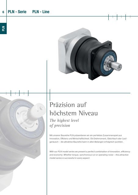
7PLN> geringstes Verdrehspiel ( hohe Abtriebsdrehmomente> PCS-2 serienmäßig> hoher Wirkungsgrad (98%)> gehonte Verzahnung> 14 Übersetzungen i=3,...,100> geringes Geräusch (< 58 dB(A))> hohe Qualität (ISO 9001)> beliebige Einbaulage> einfacher Motoranbau> Lebensdauerschmierung> weitere Optionen> Laufrichtung gleichsinnig> ausgewuchtetes Motorritzel> minimal backlash ( high output torque> PCS-2 is standard> high degree of efficiency (98%)> honed gearing> 14 Transmission ratios i=3,...,100> low noise (< 58 dB(A))> high quality (ISO 9001)> universal mounting positions> simple motor mounting> permanent lubrication> further options> equidirectional rotation> balanced motor pinion1 technische Datentechnical data2 Abmessungendimensions3 Optionenoptions4 Motoranbaumöglichkeitenpossible motor mounting5 Schnittdarstellungsectional drawing6 Bestellbezeichnungordering code7 Getriebeauswahlgearhead sizing/selection8 Einheitenumrechnungconversion table9 CAD-Zeichnungen, MaßblätterCAD drawings, dimension sheets10 Auslegung/Berechnungdimensioning/calculationSeite 8page 8Seite 11page 11Seite 12page 12Seite 13page 13Seite 17page 17Seite 18page 18Seite 88page 89Seite 92page 93www.neugart.dewww.neugart.deNCP SoftwareNCP Software
8 PLN - Serie technische Daten PLN - Line technical dataPLNBaugröße size PLN 70 PLN 90 PLN 115 PLN 142 PLN 190 i (1) Z (2)AbtriebsdrehmomentT 2N (3)(5)nominal output torqueT 2N(3)(5)Nm45 100 230 450 1000 360 140 300 600 1300 465 140 260 750 1600 540 80 150 450 1000 827 60 125 305 630 1068 120 250 780 1500 1268 120 250 780 1500 1577 150 300 1000 1800 1677 150 300 1000 1800 2065 140 260 900 1800 2577 150 300 1000 1800 3265 140 260 900 1800 4040 80 150 450 1000 6427 60 125 305 630 10012Baugröße size PLN 70 PLN 90 PLN 115 PLN 142 PLN 190 i (1) Z (2)72 160 368 720 1600 396 224 480 960 2080 4104 224 416 1200 2560 5 164 128 240 720 1600 843 96 200 488 1008 10109 192 400 1248 2400 12max. Abtriebsmoment (3)(5)(8) max. output torque (3)(5)(8) Nm109 192 400 1248 2400 15123 240 480 1600 2880 16123 240 480 1600 2880 20104 224 416 1440 2880 25 2123 240 480 1600 2880 32104 224 416 1440 2880 4064 128 240 720 1600 6443 96 200 488 1008 100Serie line PLN Z (2)Lebensdauerlifetime20.000hLebensdauer bei T 2N x 0,88 lifetime at T 2N x 0,88 30.000Not-Aus Moment (6) emergency stop (6) Nm 2 - faches T 2N /2 - times of T 2NWirkungsgrad bei Volllast (7) efficiency with full load (7) %Betriebstemperatur min. (4) min. operating temp. (4) -25°CBetriebstemperatur max. (4) max. operating temp. (4) +90Schutzart degree of protection IP 6598 195 2Schmierung lubrication Lebensdauer-Schmierung /life lubricationEinbaulage mounting position beliebig /anyMotorflanschgenauigkeitmotor flange precision DIN 42955-R(1)Übersetzungen (i=n an /n ab )(2)Anzahl Getriebestufen(3)die Angaben beziehen sich auf eine Abtriebswellendrehzahl vonn 2 =100min -1 und Anwendungsfaktor K A =1 sowie S1-Betriebsart fürelektrische Maschinen und T=30°C(4)bezogen auf die Mitte der Gehäuseoberfläche(5)abhängig vom jeweiligen Motorwellendurchmesser(6)1000-mal zulässig(7)übersetzungsabhängig, n 2 =100min -1(8)zulässig für 30.000 Umdrehungen der Abtriebswelle; siehe Seite 90(1)ratios (i=n an /n ab )(2)number of stages(3)these values refer to a speed of the output shaft of n 2 =100min -1 onduty cycle K A =1 and S1-mode for electrical machines and T=30°C(4)refering to the middle of the body surface(5)depends on the motor shaft diameter(6)allowed 1000 times(7)depends on ratio, n 2 =100min -1(8)allowable for 30.000 revolutions at the output shaft; see page 91
PLN - Serie technische Daten PLN - Line technical data9Baugröße size PLN 70 PLN 90 PLN 115 PLN 142 PLN 190 Z (2)Verdrehspiel (8) backlash (8) arcmin
PLN - Serie Abmessungen PLN - Line dimensions11PLNBaugröße size PLN 70 PLN 90 PLN 115 PLN 142 PLN 190 Z (2)Alle Maße in mmall dimensions in mmL1 Gesamtlänge (3) L1 overall length (3) 137,5 159,5 201 276 310,5 1166,5 191,5 241 335 382,5 2L2 GehäuselängeAbtriebL2 body lengthoutput59 64,5 61,5 91,5 116 188 96,5 101,5 150,5 188 2D3 Wellendurchmesser D3 shaft diameter k6 16 22 32 40 55L3 Wellenlänge Abtrieb L3 shaft length from output 48 56 88 110 112D5 Zentrierung D5 centering g7 60 70 90 130 160D6 Diagonalmaß D6 diagonal dimension 92 100 140 185 240D1 Flanschlochkreis D1 flange hole circle 68-75 85 120 165 215D2 Anschraubbohrung D2 mounting bore 4x 5,5 6,5 8,5 11 13,5Q1 Getriebequerschnitt Q1 gear box section 70 80 110 142 190D4 Wellenansatz D4 shaft root -3 35 40 45 70 80L4 Wellenl. bis Bund L4 shaft length from spigot 28 36 58 80 82L7 Zentrierbund L7 spigot depth 19 17,5 28 28 28L5 Fasenlänge L5 bevel length 8 6 8 8 10L8 Flanschdicke L8 flange thickness 7 8 10 12 15Fw Fasenwinkel Fw bevel angle ° 5 5 5 5 5AntriebinputD20 Bohrung (1)(4) D20 pinion bore (1)(4) 11 14 19 24 32L20 Wellenlänge Motor (3) L20 motor shaft length (3) 23 30 40 50 60D21 Zentr. Ø für Motor (1)D21 center bore formotor (1) 60 80 95 130 180D22 Lochkreis (1) D22 hole circle (1) 75 100 115 165 215D23 Diagonalmaß D23 diagonal dimension 92 116 145 185 240G3 Anschraubgewindex Tiefe (1)G3 mounting threadx depth (1) 4x M5 x 10 M6 x 12 M8 x 16 M10 x 20 M12 x 24L21 Zentrierung Antrieb L21 motor location depth 3 3,5 3,5 4 5Q3 Flanschquerschnitt (1) Q3 flange section (1) 70 90 115 142 190L22 Motorflanschlänge (3) L22 motor flange length (3) 30,5 39 51,5 74,5 82,5(1)je nach Motor andere Maße, siehe Seite 13(2)Anzahl Getriebestufen(3)Bei längeren Motorwellen L20 verlängert sich die Motor flanschlängeL 22 und die Gesamtlänge L1(4)für Wellenpassung: j6 ; k6(1)dimensions refer to the mounted motor-type, see page 13(2)number of stages(3)for longer motor shafts L20 applies: The measure motor flangelength L22 and the overall length L1 will be lengthen(4)for shaft fit: j6 ; k6
12 PLN - Serie Optionen PLN - Line optionsPLNOP 2:MotoranbauAbmessungen Seite 13OP 2:motor mountingdimensions page 13OP 5: Zahnwellenverbindung (1)Abmessungen Seite 14OP 5: spline shaft (1)dimensions page 14OP 7:Abtriebswelle mit PaßfederDIN 6885 T1 (1)Abmessungen Seite 14OP 7:output shaft with keyDIN 6885 T1 (1)dimensions page 14OP 8: Sonderabtriebswelle (1)Abmessungen Seite 14OP 8: special shaft (1)dimensions page 14OP 14:Abmessungen für denPLS-AbtriebAbmessungen Seite 15OP 14:dimensions for thePLS outputdimensions page 15weitere Optionen auf Anfrageother options on inquiry(1)auf Anfrage(1)on inquiry
PLN - Serie Optionen PLN - Line options13OP 2: MotoranbaumöglichkeitenOP 2: possible motor mountingPLNBaugröße size PLN 70 PLN 90 PLN 115 PLN 142 PLN 190 Z (2)D30 Motorwellendurchmesser(1)(5)D30 motor shaftdiameter (1)(5)mm8/9/9,525/10/11/12/14/16/199,525/10/11/12/12,7/14/16/19/22/2411/12,7/14/15,87/16/19/22/24/28/32/3519/22/24/28/32/35/38/4224/28/32/35/38/42/48L30 min. Motorwellenlängelength (1) L30 min. motor shaft16 (19 (6) ) 19 (21 (7) ) 21 (26 (8) ) 26 (29 (9) ) 30D31 ZentrierdurchmesserD31 motor spigot (3) beliebig/any beliebig/any beliebig/any beliebig/any beliebig/anyD33 LochkreisdurchmesserD33 hole circle diameter (3) beliebig/any beliebig/any beliebig/any beliebig/any beliebig/anyMotorbauform (1) motor type (1) B5 B5 B5 B5 B5D32 Bohrung (3) D32 pinion bore (3) beliebig/any beliebig/any beliebig/any beliebig/any beliebig/anyN AnzahlBohrungenN numbers of mountingbores4 4 4 4 4L31 Zentrierlänge L31 spigot depth beliebig/any beliebig/any beliebig/any beliebig/any beliebig/anyQ3 Flanschquerschnitt (1) Q3 flange section (1) 70 90 115 140 190max. Motorgewicht (4) max. motor weight (4) kg 10 15 34 50 75Drehm. Spannschraube torque clamping screw Nm 4,5 9,5 9,5 16,5 16,5 40 40 75 75SW Schlüsselweite SW wrench width mm 3 4 4 5 5 6 6 8 8(1)andere Abmessungen auf Anfrage(2)Anzahl Getriebestufen(3)innerhalb der Flanschabmessungen(4)bei horizontaler und stationärer Einbaulage(5)Wellenpassung: j6; k6(6)D30 > 14 mm(7)D30 > 19 mm(8)D30 > 24 mm(9)D30 > 35 mm(1)other dimensions on inquiry(2)number of stages(3)if possible with the given flange dimensions(4)refered to horizontal and stationary mounting(5)shaft fit: j6; k6(6)D30 > 14 mm(7)D30 > 19 mm(8)D30 > 24 mm(9)D30 > 35 mm
14 PLN - Serie Optionen PLN - Line optionsPLNOP 5: Zahnwellenverbindung (4) OP 5: spline shaft (4)BaugrößesizeZahnwellenverbindungspline shaftVerzahnungsbreitetooth widthZ ZentrierbohrungZ centre borePLN 70 DIN 5480 - W 16 x 0,8 x 30 x 18 x 7 m 15 DIN 332 DR M5x12,5PLN 70-OP14 DIN 5480 - W 19 x 0,8 x 30 x 22 x 7 m 15 DIN 332 DR M6x16PLN 90 DIN 5480 - W 22 x 0,8 x 30 x 26 x 7 m 21 DIN 332 DR M8x19PLN 115 DIN 5480 - W 32 x 1,25 x 30 x 24 x 7m 42 DIN 332 DR M12x28PLN 142 DIN 5480 - W 40 x 1,25 x 30 x 30 x 7m 65 DIN 332 DR M16x35PLN 190 DIN 5480 - W 55 x 2 x 30 x 26 x 7m 65 DIN 332 DR M20x4OP 7: Abtriebswelle mit Paßfeder DIN 6885 T1 (1) (4) (1) (4)OP 7: output shaft with key DIN 6885 T1Baugröße size PLN 70 PLN 70-OP14 PLN 90 PLN 115 PLN 142 PLN 190Bezeichnung title A5 x 5 x 25 A6 x 6 x 20 A6 x 6 x 28 A10 x 8 x 50 A12 x 8 x 65 A16 x 10 x 70D3 [k6] Wellendurchmesser D3 [k6] shaft diameter16 19 22 32 40 55L5 Passfederlänge L5 key length mm 25 20 28 50 65 70L6 Abstand v. Wellenende L6 distance from shaft end 2 4 4 4 8 6Z Zentrierbohrung Z centre bore M5 x 12,5 M6 x 16 M8 x 19 M12 x 28 M16 x 35 M20 x 42max. Abtriebsmoment (2) max. output torque (2) Nm 70 75 100 250 800 1400OP 8: Sonderabtriebswelle (3)(4) OP 8: special shaft (3)(4)Wellendurchmesser shaft diameter D3Wellenl. bis Bund shaft length from spigot L4Wellenlänge Abtrieb shaft length from output L3Passfederlänge key length L5Abstand v. Wellenende distance from shaft end L6Paßfederbreite key width BZentrierbohrung centre bore Z(1)Skizze für Variablen siehe OP 8(2)nur bei schwellender Belastung(3)Seite kopieren und ausgefüllt zufaxen oder Skizze zu Anfragebeilegen(4)auf Anfrage(1)sketch for variables see OP 8(2)only for tumscent load(3)fax page with data or send sketch with your inquiry(4)on inquiry
PLN - Serie Optionen PLN - Line options15OP 14: Abmessungen für den PLS-AbtriebOP 14: dimensions for the PLS outputPLNBaugrößeAlle Maße in mmsizeall dimensions in mmPLN 70OP 14PLN 90OP 14PLN 115OP 14PLN 142OP 14PLN 190OP 14L1 Gesamtlänge (3) L1 overall length (3) 137,5 159,5 201 276 310,5 1166,5 191,5 241 335 382,5 2L2 GehäuselängeAbtriebL2 body lengthoutput75 79 85 114,5 138 1104 111 125 173,5 210 2D3 Wellendurchmesser D3 shaft diameter k6 19 22 32 40 55L3 Wellenlänge Abtrieb L3 shaft length from output 32 41,5 64,5 87 90D5 Zentrierung D5 centering h7 60 80 110 130 160D6 Diagonalmaß D6 diagonal dimension 92 116 145 185 240D1 Flanschlochkreis D1 flange hole circle 75 100 130 165 215D2 Anschraubbohrung D2 mounting bore 4x 5,5 6,5 8,5 11 13,5Q1 Getriebequerschnitt Q1 gear box section 70 90 115 142 190D4 Wellenansatz D4 shaft root -3 35 40 45 70 80L4 Wellenl. bis Bund L4 shaft length from spigot 28 36 58 80 82L7 Zentrierbund L7 spigot depth 3 3 4,5 5 6L8 Flanschdicke L8 flange thickness 7 8 10 20 20AntriebinputD20 Bohrung (1)(4) D20 pinion bore (1)(4) 11 14 19 24 32L20 Wellenlänge Motor (3) L20 motor shaft length (3) 23 30 40 50 60D21 Zentr. Ø für Motor (1)D21 center bore formotor (1) 60 80 95 130 180D22 Lochkreis (1) D22 hole circle (1) 75 100 115 165 215D23 Diagonalmaß D23 diagonal dimension 92 116 145 185 240G3 Anschraubgewindex Tiefe (1)G3 mounting threadx depth (1) 4x M5 x 10 M6 x 12 M8 x 16 M10 x 20 M12 x 24L21 Zentrierung Antrieb L21 motor location depth 3 3,5 3,5 4 5Q3 Flanschquerschnitt (1) Q3 flange section (1) 70 90 115 142 190L22 Motorflanschlänge (3) L22 motor flange length (3) 30,5 39 51,5 74,5 82,5Z (2)(1)je nach Motor andere Maße, siehe Seite 13(2)Anzahl Getriebestufen(3)bei längeren Motorwellen L20 verlängert sich die MotorflanschlängeL22 und Gesamtlänge L1(4)für Wellenpassung: j6; k6(1)dimensions refer to the mounted motor-type, see page 13(2)number of stages(3)for longer motor shafts L20 applies: The measure motor flangelength L22 and overall length L1 will be lengthen(4)for shaft fit: j6; k6
16 PLN - Serie Optionen PLN - Line optionsPLNBaugrößemax. mittlere Antriebsdrehzahlbei 50% T 2N und S1 (2)(3)sizePLN 70OP 14PLN 90OP 14PLN 115OP 14PLN 142OP 14PLN 190OP 14max. middle input speed at4050 4510 2960 1720 1420 15min50% T 2N and S1 (2)(3) -1 3880 4030 3070 1490 1270 162380 2320 1740 1080 850 32580 2370 1760 1100 860 42850 2770 2220 1130 880 54110 4620 3800 1990 1660 84790 5610 4500 2570 2240 103630 3920 2960 1480 1220 124300 4620 3530 1730 1480 204780 5150 4090 2040 1660 255160 5980 4610 2310 2030 325600 6000 5220 2660 2240 406000 6000 5500 3680 3130 646000 6000 5500 4300 3500 100i (1)Baugrößemax. mittlere Antriebsdrehzahlbei 100% T 2N undS1 (2)(3)sizePLN 70OP 14PLN 90OP 14PLN 115OP 14PLN 142OP 14PLN 190OP 14max. middle input speed atmin100% T 2N and S1 (2)(3) -1 3110 3290 2020 1120 900 152960 2870 2090 940 790 161850 1680 1160 730 540 31910 1590 1100 710 520 42110 1870 1440 700 520 53410 3560 2820 1400 1120 84230 4580 3540 1980 1690 102730 2820 2020 940 760 123350 3340 2450 1110 940 203940 3910 3020 1380 1090 254230 4520 3350 1550 1360 324810 5180 4030 1900 1560 405910 6000 5500 3140 2610 646000 6000 5500 3940 3400 100i (1)(1)Übersetzungen (i=n an /n ab )(2)zulässige Betriebstemperaturen dürfen nicht überschritten werden;andere Drehzahlen auf Anfrage(3)Definition siehe Seite 92(1)ratios (i=n an /n ab )(2)allowed operating temperature must be kept; other input speeds oninquiry(3)definition see page 93
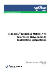
PLN - Serie Schnittdarstellung PLN - Line sectional drawing17PLN8732112496511101 Abtriebswelleaus Planetenträger und Abtriebswelle bestehende Hochleistungsbaugruppe2 Abtriebswellenlagergroße vorgespannte Präzisionskegelrollenlager für Nullspiel derAntriebswelle3 Dichtringzweckmäßige Doppellippendichtung, hält das Schmiermittel innerhalbund externe verunreinigende Substanzen außerhalb des Getriebes; IP 654 Planetenrädergeradverzahnte Präzisions-Planetenräder mit optimierter Profilmodifikationund Balligkeit; einsatzgehärtet und gehont5 Sonnenradpräzisionsgefertigtes optimiertes Verzahnungsprofil, gehärtet, gehont fürhohe Belastbarkeit, geräuscharmen Betrieb, minimalen Verschleiß undgleichbleibendes Verdrehspiel6 SonnenradlagerHochgeschwindigkeits-Rillenkugellager als Loslager zur Vermeidung vonAxialkräften durch Wärmeausdehnung, mit genauer Sonnenradpositionfür eine einfach Montage7 Gehäuse mit integriertem Hohlradgehärtetes und durch Honen fertigbearbeitetes Hohlrad für hohe Belastbarkeit,minimalen Verschleiß und gleichbleibendes Verdrehspiel8 Motoradapterplatteerlaubt die Anpassung des Getriebes an praktisch jeden Servomotor,gefertigt aus Aluminium für eine höhere Wärmeleitfähigkeit9 Klemmringausgewuchteter Klemmring aus Stahl für hohe Drehzahlen und für starkeSpannkräfte zur sicheren Übertragung von Drehmomenten10 Klemmschraubehochbelastbare Stahlschraube mit spezieller niedriger Gewindesteigungfür hohe Spannkräfte11 PCS-2 SystemPräzisionsspannsystem - das zuverlässigste und genaueste System, dasauf dem Markt angeboten wird12 MontagebohrungZugangsbohrung für die Spannschraube123456789101112output shafthigh strength one piece planet carrier & output shaftoutput shaft bearinglarge high precision preloaded taper roller bearings for zero clearancesealing ringdedicated double lip seal, keeps the lubricant inside, the external contaminantoutside the gearbox; IP 65planet gearprecison zero helix angle gear with optimized profile modifications andcrowning; case hardened and hard finished by honingsun gearprecision machined optimized gear profile, case hardened and honed forhigh load ability, low noise run, minimum wear and consistant backlashbearing for sun gearhigh speed ball bearings in floating design eliminating thrust loads fromthermal expansion, yet providing exact sungear position for easy mountinghousing with integrated ring gearring gear case hardened and hard finished, honed for high load ability,minimum wear, consistent backlashmotor adapter plateallows to match up the gear head with virtually any servo motor, made ofaluminum for enhanced thermal conductivityclamping ringbalanced ring sutiable for high rpm, made of steel to allow high clampingforces for safe torque transferclamping screwhigh strength steel screw with special low pitch thread to generate a highclamping forcePCS-2 SystemPrecision Clamping System - most reliable advanced system availabletodayassembly boreaccess bore for the clamping screw
18 PLN - Serie Bestellbezeichnung PLN - Line ordering codePLNPLN 115 - 100 / MOTOR - OP 2 + 5 + ...Getriebetyp / gear box sizePLN 70; PLN 90; PLN 115;PLN 142; PLN 190Motorbezeichnung(Herstellertyp)motor designation(manufacturer-type)Übersetzung i / ratio i1-stufig / 1-stage:3; 4; 5; 8; 102-stufig / 1-stage:12; 15; 16; 20; 25;32; 40; 64; 100OptionenoptionsOP 2: Motoranbau motor mountingOP 5: Zahnwellenverbindungspline shaftOP 7: Abtriebswelle mitPaßfederoutput shaft withkey DIN 6885 T1DIN 6885 T1OP 8: Sonderabtriebswellespecial shaftOP 14:Abmessungen fürden PLS-Abtriebdimensions for thePLS output
Für Ihre Notizen for your notes19weitere Informationenother informationswww.neugart.dewww.neugart.de
20 WPLN - Serie WPLN - LineWPLNKompakt, kraftvoll,konsequent leiseCompact, powerful,yet quietHöhere Effizienz, bessere Performance, mehr Laufruhe: Unsere neue Baureiheüberzeugt durch sein reduziertes Laufgeräusch, seine kompakte Bauweise und seineverbesserte Montagefreundlichkeit.Higher efficiencies, better performance, quieter operation: Our new model seriesdistinguishes itself with its reduced operating noise, compact design and its improvedease of assembly.
21> geringstes Verdrehspiel ( hohe Abtriebsdrehmomente> geringer Bauraum> hoher Wirkungsgrad (96%)> 11 Übersetzungen i=4,...,100> geringes Geräusch (< 66 dB(A))> hohe Qualität (ISO 9001)> beliebige Einbaulage> einfacher Motoranbau> Lebensdauerschmierung> weitere Optionen> Laufrichtung siehe Seite 31> ausgewuchtete Motoranbindung> minimal backlash ( high output torque> small installation space> high degree of efficiency (96%)> 11 Transmission ratios i=4,...,100> low noise (< 66 dB(A))> high quality (ISO 9001)> universal mounting positions> simple motor mounting> permanent lubrication> further options> direction of rotation see page 31> balanced motor connectionWPLN1 technische Datentechnical data2 Abmessungendimensions3 Optionenoptions4 Motoranbaumöglichkeitenpossible motor mounting5 Schnittdarstellungsectional drawing6 Bestellbezeichnungordering code7 Getriebeauswahlgearhead sizing/selection8 Einheitenumrechnungconversion table9 CAD-Zeichnungen, MaßblätterCAD drawings, dimension sheets10 Auslegung/Berechnungdimensioning/calculationSeite 22page 22Seite 25page 25Seite 26page 26Seite 27page 27Seite 31page 31Seite 32page 32Seite 88page 89Seite 92page 93www.neugart.dewww.neugart.deNCP SoftwareNCP Software
22 WPLN - Serie technische Daten WPLN - Line technical dataWPLNBaugröße size WPLN 70 WPLN 90 WPLN 115 WPLN 142 i (1) Z (2)AbtriebsdrehmomentT 2N (3)(5)nominal output torqueT 2N(3)(5)Nm45 90 160 - 442 75 140 - 527 50 90 - 822 40 75 - 1077 150 300 640 1677 150 300 800 2065 140 260 700 2577 108 200 360 3265 135 250 450 4040 80 150 450 6427 60 125 305 10012Baugröße size WPLN 70 WPLN 90 WPLN 115 WPLN 142 i (1) Z (2)72 144 256 - 467 120 224 - 543 80 144 - 8135 64 120 - 10123 240 480 1024 16max. Abtriebsmoment (3)(5)(8) max. output torque (3)(5)(8) Nm 123 240 480 1280 20104 224 416 1120 25123 172 320 576 32 2104 216 400 720 4064 128 240 720 6443 96 200 488 100Serie line WPLN Z (2)Lebensdauerlifetime20.000hLebensdauer bei T 2N x 0,88 lifetime at T 2N x 0,88 30.000Not-Aus Moment (6) emergency stop (6) Nm 2 - faches T 2N /2 - times of T 2NWirkungsgrad bei Volllast (7) efficiency with full load (7) %Betriebstemperatur min. (4) min. operating temp. (4) -25°CBetriebstemperatur max. (4) max. operating temp. (4) +90Schutzart degree of protection IP 6596 194 2Schmierung lubrication Lebensdauer-Schmierung /life lubricationEinbaulage mounting position beliebig /anyMotorflanschgenauigkeitDrehrichtungmotor flange precision DIN 42955-RDirection of rotationAn- Abtriebseite gegensinnig/Drive and output sides in opposite directions(1)Übersetzungen (i=n an /n ab )(2)Anzahl Getriebestufen(3)die Angaben beziehen sich auf eine Abtriebswellendrehzahl vonn 2 =100min -1 und Anwendungsfaktor K A =1 sowie S1-Betriebsart fürelektrische Maschinen und T=30°C(4)bezogen auf die Mitte der Gehäuseoberfläche(5)abhängig vom jeweiligen Motorwellendurchmesser(6)1000-mal zulässig(7)übersetzungsabhängig, n 2 =100min -1(8)zulässig für 30.000 Umdrehungen der Abtriebswelle; siehe Seite 90(1)ratios (i=n an /n ab )(2)number of stages(3)these values refer to a speed of the output shaft of n 2 =100min -1 onduty cycle K A =1 and S1-mode for electrical machines and T=30°C(4)refering to the middle of the body surface(5)depends on the motor shaft diameter(6)allowed 1000 times(7)depends on ratio, n 2 =100min -1(8)allowable for 30.000 revolutions at the output shaft; see page 91
WPLN - Serie technische Daten WPLN - Line technical data23Baugröße size WPLN 70 WPLN 90 WPLN 115 WPLN 142 Z (2)Verdrehspiel (8) backlash (8) arcmin
24 WPLN - Serie technische Daten WPLN - Line technical dataWPLNBaugröße size WPLN 70 WPLN 90 WPLN 115 WPLN 142 i (1)0,654 1,331 5,924 - 40,6 1,168 5,441 - 50,532 1,004 4,989 - 80,516 0,966 4,883 - 100,639 0,642 1,366 6,082 16Trägheitsmoment (2) inertia (2) kgcm² 0,591 0,593 1,190 6,016 200,590 0,591 1,186 5,5 250,528 0,529 1,013 5,028 320,528 0,528 1,011 5,012 400,528 0,528 1,01 5,004 640,514 0,514 0,97 4,892 100(1)Übersetzungen (i=n an /n ab )(2)das Trägheitsmoment bezieht sich auf die Antriebswelle und aufStandardmotorwellendurchmesser D20(1)ratios (i=n an /n ab )(2)the moment of inertia relates to th e input shaft and tostandard motor shaft diameter D20
WPLN - Serie Abmessungen WPLN - Line dimensions25WPLNBaugröße size WPLN 70 WPLN 90 WPLN 115 WPLN 142 Z (2)Alle Maße in mmall dimensions in mmL1 GesamtlängeL1 overall length137,5 165 218 - 1185 207 248,5 342,5 2L2 GehäuselängeL2 body length46,5 60,5 73,5 - 194 108 112 176 2136 151 187,5 - 1L23 Achshöhe (3) L23 Axle height 3) 136 136 151 187,5 2A1 AchsversatzA1 Axle offset10 14 20 - 110 10 14 20 2AbtrieboutputD3 Wellendurchmesser D3 shaft diameter k6 16 22 32 40L3 Wellenlänge Abtrieb L3 shaft length from output 48 56 88 110D5 Zentrierung D5 centering g7 60 70 90 130D6 Diagonalmaß D6 diagonal dimension 92 100 140 185D1 Flanschlochkreis D1 flange hole circle 68-75 85 120 165D2 Anschraubbohrung D2 mounting bore 4x 5,5 6,5 8,5 11Q1 Getriebequerschnitt Q1 gear box section 70 80 110 142D4 Wellenansatz D4 shaft root -330 40 45 70 135 40 45 70 2L4 Wellenl. bis Bund L4 shaft length from spigot 28 36 58 80L7 Zentrierbund L7 spigot depth 19 17,5 28 28L5 Fasenlänge L5 bevel length 8 6 8 8L8 Flanschdicke L8 flange thickness 7 8 10 12Fw Fasenwinkel Fw bevel angle ° 5 5 5 586 105 120 - 1D9 max. Durchmesser D9 max. diameter86 86 105 120 2Antriebinput11 14 19 - 1D20 Bohrung (1)(4) D20 pinion bore (1)(4) 11 11 14 19 223 30 40 - 1L20 Wellenlänge Motor (3) L20 motor shaft length (3) 23 23 30 40 2D21 center bore for60 80 95 - 1D21 Zentr. Ø für Motor (1)motor (1) 60 60 80 95 275 100 115 - 1D22 Lochkreis (1) D22 hole circle (1) 75 75 100 115 292 116 145 - 1D23 Diagonalmaß (1) D23 diagonal dimension (1) 92 92 116 145 2G3 Anschraubgewindex Tiefe (1)L21 Zentrierung AntriebG3 mounting threadx depth (1)L21 motor location depth4xM5 x 10 M6 x 12 M8 x 16 - 1M5 x 10 M5 x 10 M6 x 12 M8 x 16 23 3,5 3,5 - 13 3 3,5 3,5 2Q3 Flanschquerschnitt (1) Q3 flange section (1) 70 90 115 - 170 70 90 115 2L22 Adapterplattenlänge (3) L22 Adapter plate length (3) 19 25,5 27,5 - 119 19 25,5 27,5 2(1)je nach Motor andere Maße, siehe Seite 27(2)Anzahl Getriebestufen(3)bei längeren Motorwellen L20 verlängert sich die MotorflanschlängeL22 und die Achshöhe L23(4)für Wellenpassung: j6 ; k6(1)dimensions refer to the mounted motor-type, see page 27(2)number of stages(3)for longer motor shafts L20 applies: The measure motor flangelength L22 and the Axle height L23 will be lengthen(4)for shaft fit: j6 ; k6
26 WPLN - Serie Optionen WPLN - Line optionsOP 2:MotoranbauAbmessungen Seite 27OP 2:motor mountingdimensions page 27WPLNOP 5: Zahnwellenverbindung (1)Abmessungen Seite 28OP 5: spline shaft (1)dimensions page 28OP 7:Abtriebswelle mit PaßfederDIN 6885 T1 (1)Abmessungen Seite 28OP 7:output shaft with keyDIN 6885 T1 (1)dimensions page 28OP 8: Sonderabtriebswelle (1)Abmessungen Seite 28OP 8: special shaft (1)dimensions page 28OP 14:Abmessungen für denWPLS-AbtriebAbmessungen Seite 29OP 14:dimensions for theWPLS outputdimensions page 29weitere Optionen auf Anfrageother options on inquiry(1)auf Anfrage(1)on inquiry
WPLN - Serie Optionen WPLN - Line options27OP 2: MotoranbaumöglichkeitenOP 2: possible motor mountingWPLNSWBaugröße size WPLN 70 WPLN 90 WPLN 115 WPLN 142 Z (2)D30 Motorwellendurchmesser(1)(5)L30 min. Motorwellenlänge(1)D30 motor shaftdiameter (1)(5)mm8/9/9,525/10/11/12/14/16/198/9/9,525/10/11/12/14/16/199,525/10/11/12/12,7/14/16/19/22/248/9/9,525/10/11/12/12,7/14/16/1911/12,7/14/15,87/16/19/22/24/28/32/359,525/10/11/12,7/14/15,87/16/19/22/24- 111/12,7/14/15,87/16/19/22/24/ 28/32/35L30 min. motor shaft20 (23 (6) ) 23 (25 (7) ) 25 (32 (8) ) - 1length (1) 20 (23 (6) ) 20 (23 (6) ) 23 (25 (7) ) 25 (32 (8) ) 2D31 ZentrierdurchmesserD31 motor spigot (3) beliebig/any beliebig/any beliebig/any beliebig/anyD33 LochkreisdurchmesserD33 hole circle diameter (3) beliebig/any beliebig/any beliebig/any beliebig/anyMotorbauform (1) motor type (1) B5 B5 B5 B5D32 Bohrung (3) D32 pinion bore (3) beliebig/any beliebig/any beliebig/any beliebig/anyN Anzahl BohrungenN numbers of mountingbores4 4 4 4L31 Zentrierlänge L31 spigot depth beliebig/any beliebig/any beliebig/any beliebig/anyQ3 Flanschquerschnitt (1) Q3 flange section (1) 70 90 115 140max. Motorgewicht (4) max. motor weight (4) kg 10 15 34 50Drehm. Spannschraube torque clamping screw Nm 4,5 9,5 (6) 9,5 16.5 (7) 16,5 40 (8) 16,5 40 (9)SW Schlüsselweite SW wrench width mm 3 4 (6) 4 5 (7) 5 6 (8) 5 6 (9)2(1)andere Abmessungen auf Anfrage(2)Anzahl Getriebestufen(3)innerhalb der Flanschabmessungen(4)bei horizontaler und stationärer Einbaulage(5)Wellenpassung: j6; k6(6)D30 > 14 mm(7)D30 > 19 mm(8)D30 > 24 mm(9)D30 = 42 mm(1)other dimensions on inquiry(2)number of stages(3)if possible with the given flange dimensions(4)refered to horizontal and stationary mounting(5)shaft fit: j6; k6(6)D30 > 14 mm(7)D30 > 19 mm(8)D30 > 24 mm(9)D30 = 42 mm• thermischer Längenausgleich bezogen auf das A-Lagerschilddes Motors• thermal length compensation with respect to the A end shield ofthe motor
28 WPLN - Serie Optionen WPLN - Line optionsOP 5: Zahnwellenverbindung (4) OP 5: spline shaft (4)WPLNBaugrößesizeZahnwellenverbindungspline shaftVerzahnungsbreitetooth widthZ ZentrierbohrungZ centre boreWPLN 70 DIN 5480 - W 16 x 0,8 x 30 x 18 x 7 m 15 DIN 332 DR M5x12,5WPLN 70-OP14 DIN 5480 - W 19 x 0,8 x 30 x 22 x 7 m 15 DIN 332 DR M6x16WPLN 90 DIN 5480 - W 22 x 0,8 x 30 x 26 x 7 m 21 DIN 332 DR M8x19WPLN 115 DIN 5480 - W 32 x 1,25 x 30 x 24 x 7m 42 DIN 332 DR M12x28WPLN 142 DIN 5480 - W 40 x 1,25 x 30 x 30 x 7m 65 DIN 332 DR M16x35OP 7: Abtriebswelle mit Paßfeder DIN 6885 T1 (1) (4) (1) (4)OP 7: output shaft with key DIN 6885 T1Baugröße size WPLN 70 WPLN 70-OP14 WPLN 90 WPLN 115 WPLN 142Bezeichnung title A5 x 5 x 25 A6 x 6 x 20 A6 x 6 x 28 A10 x 8 x 50 A12 x 8 x 65D3 [k6] Wellendurchmesser D3 [k6] shaft diameter16 19 22 32 40L5 Passfederlänge L5 key length mm 25 20 28 50 65L6 Abstand v. Wellenende L6 distance from shaft end 2 4 4 4 8Z Zentrierbohrung Z centre bore M5 x 12,5 M6 x 16 M8 x 19 M12 x 19 M16 x 35max. Abtriebsmoment (2) max. output torque (2) Nm 70 75 100 250 800OP 8: Sonderabtriebswelle (3)(4) OP 8: special shaft (3)(4)Wellendurchmesser shaft diameter D3Wellenl. bis Bund shaft length from spigot L4Wellenlänge Abtrieb shaft length from output L3Passfederlänge key length L5Abstand v. Wellenende distance from shaft end L6Paßfederbreite key width BZentrierbohrung centre bore Z(1)Skizze für Variablen siehe OP 8(2)nur bei schwellender Belastung(3)Seite kopieren und ausgefüllt zufaxen oder Skizze zu Anfrage beilegen(4)auf Anfrage(1)sketch for variables see OP 8(2)only for tumscent load(3)fax page with data or send sketch with your inquiry(4)on inquiry
WPLN - Serie Optionen WPLN - Line options29OP 14: Abmessungen für den WPLS-AbtriebOP 14: dimensions for the WPLS outputWPLNBaugröße size WPLN 70 OP 14 WPLN 90 OP 14 WPLN 115 OP 14 WPLN 142 OP 14 Z (2)Alle Maße in mmall dimensions in mmL1 GesamtlängeL1 overall length137,5 165 218 - 1185 207 248,5 342,5 2L2 GehäuselängeL2 body length62,5 75 97 - 1110 122,5 135,5 199 2136 151 187,5 - 1L23 Achshöhe (3) L23 Axle height 3) 136 136 151 187,5 2A1 AchsversatzA1 Axle offset10 14 20 - 110 10 14 20 2AbtrieboutputD3 Wellendurchmesser D3 shaft diameter k6 19 22 32 40L3 Wellenlänge Abtrieb L3 shaft length from output 32 41,5 64,5 87D5 Zentrierung D5 centering h7 60 80 110 130D6 Diagonalmaß D6 diagonal dimension 92 116 145 185D1 Flanschlochkreis D1 flange hole circle 75 100 130 165D2 Anschraubbohrung D2 mounting bore 4x 5,5 6,5 8,5 11Q1 Getriebequerschnitt Q1 gear box section 70 80 110 142D4 Wellenansatz D4 shaft root -330 40 45 70 135 40 45 70 2L4 Wellenl. bis Bund L4 shaft length from spigot 28 36 58 80L7 Zentrierbund L7 spigot depth 3 3 4,5 5L8 Flanschdicke L8 flange thickness 7 8 10 2086 105 120 - 1D9 max. Durchmesser D9 max. diameter86 86 105 120 2Antriebinput11 14 19 - 1D20 Bohrung (1)(4) D20 pinion bore (1)(4) 11 11 14 19 223 30 40 - 1L20 Wellenlänge Motor (3) L20 motor shaft length (3) 23 23 30 40 2D21 center bore for motor(1) 60 60 80 95 260 80 95 - 1D21 Zentr. Ø für Motor (1)75 100 115 - 1D22 Lochkreis (1) D22 hole circle (1) 75 75 100 115 292 116 145 - 1D23 DiagonalmaßD23 diagonal dimension92 92 116 145 2G3 Anschraubgewindex Tiefe (1)L21 Zentrierung AntriebG3 mounting threadx depth (1)L21 motor location depth4xM5 x 10 M6 x 12 M8 x 16 - 1M5 x 10 M5 x 10 M6 x 12 M8 x 16 23 3,5 3,5 - 13 3 3,5 3,5 2Q3 Flanschquerschnitt (1) Q3 face section (1) 70 90 115 - 170 70 90 115 2L22 Adapterplattenlänge (3) L22 Adapter plate length (3) 19 25,5 27,5 - 119 19 25,5 27,5 2(1)je nach Motor andere Maße, siehe Seite 27(2)Anzahl Getriebestufen(3)bei längeren Motorwellen L20 verlängert sich die MotorflanschlängeL22 und die Achshöhe L23(4)für Wellenpassung: j6 ; k6(1)dimensions refer to the mounted motor-type, see page 27(2)number of stages(3)for longer motor shafts L20 applies: The measure motor flangelength L22 and the Axle height L23 will be lengthen(4)for shaft fit: j6 ; k6
30 WPLN - Serie Optionen WPLN - Line optionsWPLNBaugröße size WPLN 70 OP 14 WPLN 90 OP 14 WPLN 115 OP 14 WPLN 142 OP 14 i (1)max. mittlere Antriebsdrehzahlbei 50% T 2N und S1 (2)(3)max. middle input speed at50% T 2N and S1 (2)(3) 3150 3200 2700 1600 202650 2250 1600 - 43000 2700 1800 - 53850 3450 2250 - 84150 3800 2400 - 102900 2900 2400 1550 163450 3600 3100 1850 253550 3950 3450 2300 323800 4150 3600 2400 404200 4900 4350 2700 644450 5300 4700 3000 100Baugröße size WPLN 70 OP 14 WPLN 90 OP 14 WPLN 115 OP 14 WPLN 142 OP 14 i (1)max. mittlere Antriebsdrehzahlbei 100% T 2N undS1 (2)(3)100% T 2N and S1 (2)(3) 2600 2450 1950 1100 201900 1600 1100 - 42250 1950 1300 - 53200 2850 1850 - 83600 3250 2050 - 10max. middle input speed at2350 2150 1700 1100 163000 2850 2400 1350 253050 3350 2850 1950 323400 3450 2950 2000 404000 4550 4000 2350 644350 5050 4450 2800 100(1)Übersetzungen (i=n an /n ab )(2)zulässige Betriebstemperaturen dürfen nicht überschritten werden;andere Drehzahlen auf Anfrage(3)Definition siehe Seite 92(1)ratios (i=n an /n ab )(2)allowed operating temperature must be kept; other input speeds oninquiry(3)definition see page 93
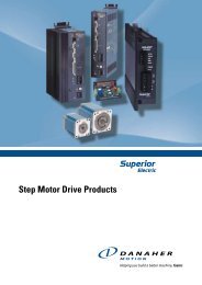
WPLN - Serie Schnittdarstellung WPLN - Line sectional drawing31784WPLN6529 10131 Abtriebswelleaus hochfestem Edelstahl für höchste Wellensicherheiten2 Abtriebswellenlagergroße vorgespannte Präzisionskegelrollenlager für Nullspiel derAbtriebswelle3 Dichtringzweckmäßige Doppellippendichtung, hält das Schmiermittel innerhalbund externe verunreinigende Substanzen außerhalb des Getriebes; IP 654 HypoidradVerzahnung optimiert auf höchste Tragfähigkeit und Laufruhe5 HypoidritzelVerzahnung optimiert auf höchste Tragfähigkeit und Laufruhe6 Antriebswellenlagerungvorgespannte Präzisionskegelrollenlager für Nullspiel derAntriebswelle7 Getriebegehäuseschwarzes korrosionsgeschütztes Gehäuse aus Aluminium für geringsteMasse und optimalen Montagekomfort8 Motoradapterplatteerlaubt die Anpassung des Getriebes an praktisch jeden Servomotor,gefertigt aus Aluminium für eine höhere Wärmeleitfähigkeit9 Kupplungausgewuchtete Kupplung für hohe Drehzahlen und für starke Spannkräftezur sicheren Übertragung von Drehmomenten10 Klemmschraubehochbelastbare Stahlschraube zur sicheren Übertragung vonDrehmomenten1 output shaftmade of high-strength stainless steel for utmost shaft reliabilities2 output shaft bearinglarge high precision preloaded taper roller bearings for zero clearance3 sealing ringdedicated double lip seal, keeps the lubricant inside, the externalcontaminant outside the gearbox; IP 654 hypoid gearGearing optimised for maximal load capacity and quiet operation5 hypoid pinionGearing optimised for maximal load capacity and quiet operation6 drive shaft bearingpretensioned precision tapered roller bearing for zero play of thedrive shaft7 gearbox housingblack corrosion-protected housing made of aluminium for minimal massand optimal ease of mounting8 motor adapter plateallows to match up the gear head with virtually any servo motor, made ofaluminum for enhanced thermal conductivity9 couplingbalanced coupling for high rotational speeds and strong tension force forreliable transfer of torques10 clamping screwheavy-duty steel screw for reliable transfer of torques
32 WPLN - Serie Bestellbezeichnung WPLN - Line ordering codeWPLNWPLN 115 - 100 / MOTOR - OP 2 + 5 + ...Getriebetyp / gear box sizeWPLN 70; WPLN 90;WPLN 115; WPLN 142Motorbezeichnung(Herstellertyp)motor designation(manufacturer-type)Übersetzung i / ratio i1-stufig / 1-stage:4; 5; 8; 102-stufig / 2-stage:16; 20; 25; 32;40; 64; 100OptionenoptionsOP 2: Motoranbau motor mountingOP 5: Zahnwellenverbindungspline shaftOP 7: Abtriebswelle mitPaßfederoutput shaft withkey DIN 6885 T1DIN 6885 T1OP 8: Sonderabtriebswellespecial shaftOP 14:Abmessungen fürden WPLS-Abtriebdimensions for theWPLS output