1RU HIGH 48V, 24V and 12V INTEGRATED DC POWER SYSTEMS
1RU HIGH 48V, 24V and 12V INTEGRATED DC POWER SYSTEMS
1RU HIGH 48V, 24V and 12V INTEGRATED DC POWER SYSTEMS

Create successful ePaper yourself
Turn your PDF publications into a flip-book with our unique Google optimized e-Paper software.
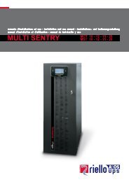
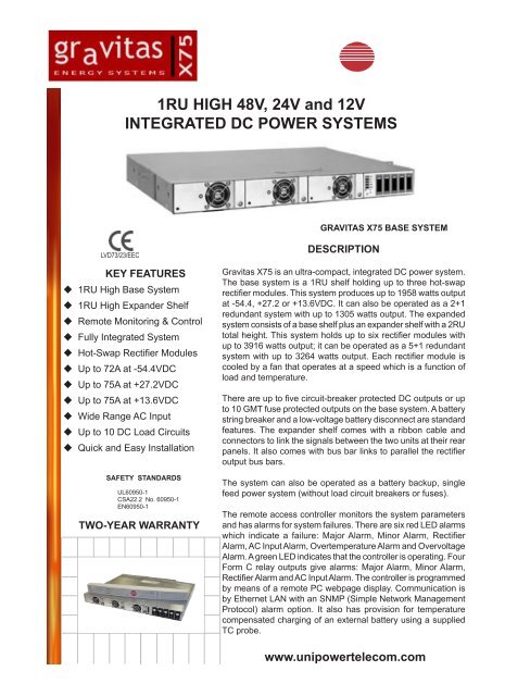
<strong>1RU</strong> <strong>HIGH</strong> <strong>48V</strong>, <strong>24V</strong> <strong>and</strong> <strong>12V</strong><strong>INTEGRATED</strong> <strong>DC</strong> <strong>POWER</strong> <strong>SYSTEMS</strong>GRAVITAS X75 BASE SYSTEMLVD73/23/EECKEY FEATURES <strong>1RU</strong> High Base System <strong>1RU</strong> High Exp<strong>and</strong>er Shelf Remote Monitoring & Control Fully Integrated System Hot-Swap Rectifier Modules Up to 72A at -54.4V<strong>DC</strong> Up to 75A at +27.2V<strong>DC</strong> Up to 75A at +13.6V<strong>DC</strong> Wide Range AC Input Up to 10 <strong>DC</strong> Load Circuits Quick <strong>and</strong> Easy InstallationSAFETY STANDARDSUL60950-1CSA22.2 No. 60950-1EN60950-1TWO-YEAR WARRANTYDESCRIPTIONGravitas X75 is an ultra-compact, integrated <strong>DC</strong> power system.The base system is a <strong>1RU</strong> shelf holding up to three hot-swaprectifier modules. This system produces up to 1958 watts outputat -54.4, +27.2 or +13.6V<strong>DC</strong>. It can also be operated as a 2+1redundant system with up to 1305 watts output. The exp<strong>and</strong>edsystem consists of a base shelf plus an exp<strong>and</strong>er shelf with a 2RUtotal height. This system holds up to six rectifier modules withup to 3916 watts output; it can be operated as a 5+1 redundantsystem with up to 3264 watts output. Each rectifier module iscooled by a fan that operates at a speed which is a function ofload <strong>and</strong> temperature.There are up to five circuit-breaker protected <strong>DC</strong> outputs or upto 10 GMT fuse protected outputs on the base system. A batterystring breaker <strong>and</strong> a low-voltage battery disconnect are st<strong>and</strong>ardfeatures. The exp<strong>and</strong>er shelf comes with a ribbon cable <strong>and</strong>connectors to link the signals between the two units at their rearpanels. It also comes with bus bar links to parallel the rectifieroutput bus bars.The system can also be operated as a battery backup, singlefeed power system (without load circuit breakers or fuses).The remote access controller monitors the system parameters<strong>and</strong> has alarms for system failures. There are six red LED alarmswhich indicate a failure: Major Alarm, Minor Alarm, RectifierAlarm, AC Input Alarm, Overtemperature Alarm <strong>and</strong> OvervoltageAlarm. A green LED indicates that the controller is operating. FourForm C relay outputs give alarms: Major Alarm, Minor Alarm,Rectifier Alarm <strong>and</strong> AC Input Alarm. The controller is programmedby means of a remote PC webpage display. Communication isby Ethernet LAN with an SNMP (Simple Network ManagementProtocol) alarm option. It also has provision for temperaturecompensated charging of an external battery using a suppliedTC probe.www.unipowertelecom.comDIV. OF UNI<strong>POWER</strong> CORP. • 3900 Coral Ridge Drive, Coral Springs, Florida 33065, USA • Tel: 954-346-2442 • Fax: 954-340-7901 • sales@unipower-corp.comUNI<strong>POWER</strong> EUROPE • Parkl<strong>and</strong> Business Centre, Chartwell Road, Lancing, BN15 8UE, ENGLAND • Tel: +44(0)1903 768200 • Fax: +44(0)1903 764540 • info@unipower-europe.com
Notes:GRAVITAS X75 SUMMARY FEATURES -48, +24, or +<strong>12V</strong><strong>DC</strong> Rectifiers Hot-Swap Rectifiers Modules Power Factor Corrected Class B EMI Input Filter Base <strong>and</strong> Exp<strong>and</strong>er Shelves N+1 Redundant Operation Up to 10 <strong>DC</strong> Load CircuitsSYSTEMCAPABILITYSystem VoltageSystem Max. CurrentSystem Current, N+1 Redundant Circuit Breakers or GMT Fuses Battery String Breaker LV Battery Disconnect Remote Monitoring & Control Quick, Easy Installation 19 or 23-Inch Rack Mounting SNMP Alarm OptionGRAVITAS X75 CAPABILITY GUIDESYSTEM CAPABILITYBASESYSTEM-54.4V<strong>DC</strong>36.0A24.0AX75-48 X75-24 X75-12EXPANDEDSYSTEM-54.4V<strong>DC</strong>72.0A60.0ABASESYSTEM+27.2V<strong>DC</strong>55.2A36.8AEXPANDEDSYSTEM+27.2V<strong>DC</strong>75.0A73.5ABASESYSTEM+13.6V<strong>DC</strong>75.0A66.0ANo. of Rectifiers, Max. 3 6 3 5 3Battery String BreakerLow Voltage DisconnectTotal No. <strong>DC</strong> Loads, Max.Option A - miniature breakersOption B - GMT fusesController FeaturesAlarm OutputsExternal Digital InputsTemp. CompensationCommunicationsEthernet TCP/IPSNMPShelf HeightMounting Width, InchesSt<strong>and</strong>ardSt<strong>and</strong>ard101-30A x 50.5A-12A x 1041St<strong>and</strong>ardSt<strong>and</strong>ardOptional<strong>1RU</strong>, Base Shelf <strong>and</strong> Expansion Shelf19 or 23 (universal reversible mounting brackets)EXPANDEDSYSTEMNOTAVAILABLE1. The exp<strong>and</strong>er shelf allows up to 3 additional rectifier modules to be connected to the rectifier bus for additional power capability.The rectifiers are paralleled to the system bus via bus bars <strong>and</strong> expansion interface connections.2. For applications not requiring battery support consult UNI<strong>POWER</strong> sales office about using Front-End power modules instead ofrectifier modules.MODULEMODEL NO.RSJ48/12-ZRSG48/10-ZRSF48/7-ZRSG24/18-ZRSF24/13-ZRSG12/33-ZRSF12/22-ZRECTIFIER MODULES vs. SYSTEM CAPACITIESOUTPUTV<strong>DC</strong>-54.4V<strong>DC</strong>-54.4V<strong>DC</strong>-54.4V<strong>DC</strong>+27.2V<strong>DC</strong>+27.2V<strong>DC</strong>+13.6V<strong>DC</strong>+13.6V<strong>DC</strong>OUTPUTAMPS12.010.17.418.412.933.022.1NO. SYST.MODULESMAX. SYST.AMPSNO. N+1MODULESN+1 SYST.AMPSBASE EXP. BASE EXP. BASE EXP. BASE EXP.33333336665536.030.322.255.238.775.066.372.060.644.475.075.02+12+12+12+12+12+12+15+15+15+14+14+124.020.214.836.825.866.044.260.050.537.073.651.6DIV. OF UNI<strong>POWER</strong> CORP. • 3900 Coral Ridge Drive, Coral Springs, Florida 33065, USA • Tel: 954-346-2442 • Fax: 954-340-7901 • sales@unipower-corp.comUNI<strong>POWER</strong> EUROPE • Parkl<strong>and</strong> Business Centre, Chartwell Road, Lancing, BN15 8UE, ENGLAND • Tel: +44(0)1903 768200 • Fax: +44(0)1903 764540 • info@unipower-europe.com
RECTIFIER MODULE SPECIFICATIONSINPUTVoltage Range _________________________ 85-264VACPower Factor ________________________________ 0.99Total Harmonic Distortion, Max. __________________ 5%Frequency ______________________________ 47-63HzInrush Current Limiting ____________________ 30A PeakEMI Filter, Conducted _______ FCC20780 pt. 15J Curve B________________________________EN55022 Curve BInput Current, max.RSJ __________________ 3.2A/230VAC, 6.2A/120VACRSG_____________ _____ 2.7A/230VAC, 5.2A/120VACRSF_____________ _____ 2.0A/230VAC, 3.8A/120VACInput Immunity, ConductedFast Transients, Line-Line _ ±2kV (EN61000-4-4 Level 3)Surges, Line-Line _______ ±2kV (EN61000-4-5 Level 3)Surges, Line-Ground _____ ±4kV (EN61000-4-5 Level 4)OUTPUTCurrent & Voltage _________________________ see tableVoltage Adjustment Range, <strong>48V</strong> Nominal _____45-58V<strong>DC</strong><strong>24V</strong> Nominal _____22-29V<strong>DC</strong><strong>12V</strong> Nominal ___ 11-14.5V<strong>DC</strong>Total Regulation, Max. _________________________ 2%Holdup Time _____________________________ 10msec.Overvoltage Protection, <strong>48V</strong> Nominal _____________ 58V<strong>24V</strong> Nominal _____________ 29V<strong>12V</strong> Nominal ___________ 14.5VFiltering: Wideb<strong>and</strong> Noise, 20Mhz BW, P-P _______ 1.0%Voice B<strong>and</strong> Noise ________________________
CONFIGURATION GUIDE1. Determine the capacity of the system desired, taking into account future expansion, then check the type of rectifier required<strong>and</strong> fill in the initial quantity to be ordered including spares. This will determine the system unit base number.BASE SYSTEMOUTPUT, MAX.BASE SYSTEMOUTPUT, N+1RECTIFIER MODULESCHECK TYPE REQ.NO. MODULESREQUIREDSYSTEM UNITBASE NUMBER-54.4V<strong>DC</strong>@36.0A-54.4V<strong>DC</strong>@30.3A-54.4V<strong>DC</strong>@22.2A-54.4V<strong>DC</strong>@24.0A-54.4V<strong>DC</strong>@20.2A-54.4V<strong>DC</strong>@14.8A RSJ48/12-Z RSG48/10-Z RSF48/7-Z_______X75-48+27.2V<strong>DC</strong>@55.2A+27.2V<strong>DC</strong>@38.7A+27.2V<strong>DC</strong>@36.8A+27.2V<strong>DC</strong>@25.8A RSG24/18-Z RSF24/13-Z_______ X75-24+13.6V<strong>DC</strong>@75.0A+13.6V<strong>DC</strong>@66.3A+13.6V<strong>DC</strong>@66.0A+13.6V<strong>DC</strong>@44.2A RSG12/33-Z RSF12/22-Z_______ X75-122. If the required capacity initially or in the future exceeds the capability of the base system check against the same rectifier typeas above <strong>and</strong> fill in the number of additional rectifiers required. This defines that an expansion unit needs to be ordered.TOTAL SYSTEMOUTPUT, MAX.-54.4V<strong>DC</strong>@72.0A-54.4V<strong>DC</strong>@60.6A-54.4V<strong>DC</strong>@44.4A+27.2V<strong>DC</strong>@75.0A+27.2V<strong>DC</strong>@75.0ATOTAL SYSTEMOUTPUT, N+1-54.4V<strong>DC</strong>@60.0A-54.4V<strong>DC</strong>@50.5A-54.4V<strong>DC</strong>@37.0A+27.2V<strong>DC</strong>@73.6A+27.2V<strong>DC</strong>@51.6ARECTIFIER MODULESCHECK TYPE REQ. RSJ48/12-Z RSG48/10-Z RGF48/7-Z RSG24/18-Z RSF24/13-ZNO. MODULESREQUIRED______________EXPANSIONUNIT NUMBERX75-ES3. Check either option A or option B for <strong>DC</strong> distribution. For option A fill in the rating <strong>and</strong> code for each breaker to be installed.For option B fill in the number of fuses for each value required including spares.<strong>DC</strong> DISTRIBUTION OPTION A: Up to 5 Breakers Total, maximum 30A each.1. Breaker ___ A, code ___ 3. Breaker ___ A, code ___ 5. Breaker ___ A, code ___2. Breaker ___ A, code ___ 4. Breaker ___ A, code ___Enter rating & code above: 1A(F), 2.5A(G), 5A(H), 10A(I), 15A(J), 20A(K), 25A(L) & 30A(M), Not required(X). OPTION B: Up to 10 GMT Fuses Total. Enter the number required below.AMPS BUSSMAN NO. COLORNO.REQ’DAMPS BUSSMAN NO. COLORNO.REQ’D0.5A GMT - 1/2 Red3 GMT - 3 Blue0.75 GMT - 3/4 Brown5 GMT - 5 Green1 GMT - 1 Gray10 GMT - 10 Red-White1.33 GMT - 1 1/3 White12 GMT - 12 Green-Yel2 GMT - 2 Orange0 GMT - Dummy Orange4. Check any options/accessories required <strong>and</strong> fill in the number of line cords if checked.OPTIONS & ACCESSORIES Additional Temperature Probe (One supplied as st<strong>and</strong>ard) SNMP - Simple Network Management ProtocolAC Line Cords: 6ft. (1.8m) with IEC60320 C-13 connector, one per rectifier position in use. 125VAC with NEMA OR 250VAC with NEMA OR 250VAC unterminated6-15 plug. 3x14AWG 6-15 plug. 3x14AWG 3 x 18AWGQty. _____ Pt. No. 364-1412-0000 Qty. _____ Pt. No. 364-1414-0000 Qty. _____ No. 364-1421-00005. Send the completed form to the relevant UNI<strong>POWER</strong> sales office <strong>and</strong> we will issue a configuration Model Number which willuse the following format.Key:• System unit Option A: X75-vv-A-bbbbb-STvv = system voltage.b = breaker code, five characters total.• System unit Option B or C: X75-vv-B-ST or X75-vv-C-STS = SNMP option fitted. (add as suffix)• Expansion unit: X75-ES (voltage independent, no options available) T = additional Temp. probe. (add as suffix)NOTE: Fuses, rectifiers, accessories <strong>and</strong> the expansion unit are supplied as separate items from the main system unit<strong>and</strong> will be detailed separetely in quotations, proposals <strong>and</strong> Sales Order documentation.x75-ds-revE-01-15-10DIV. OF UNI<strong>POWER</strong> CORP. • 3900 Coral Ridge Drive, Coral Springs, Florida 33065, USA • Tel: 954-346-2442 • Fax: 954-340-7901 • sales@unipower-corp.comUNI<strong>POWER</strong> EUROPE • Parkl<strong>and</strong> Business Centre, Chartwell Road, Lancing, BN15 8UE, ENGLAND • Tel: +44(0)1903 768200 • Fax: +44(0)1903 764540 • info@unipower-europe.com